

Page 1

i PB-007726 Rev - A
2005.07.04
PT-210M Processor/Transmitter
Operations Manual
Page 2

ii PB-007726 Rev - A
2005.07.04
1.0 INTRODUCTION 1
1.1 S
YSTEM ENHANCEMENTS
1
2.0 PT-210 HARDWARE OVERVIEW 3
2.1 S
ENSORS
3
2.1.1 S
EISMIC
3
2.1.2 M
AGNETIC
3
2.1.3 P
ASSIVE INFRARED
4
2.1.4 C
ONTACT SENSOR
4
2.2 C
AMERA TRIGGER
5
2.3 C
OMMUNICATIONS
5
2.4 A
NTENNA
5
2.5 P
OWER SOURCE
5
2.5.1 P
RIMARY SOURCE
5
2.5.2 S
ECONDARY SOURCE
6
3.0 PT-210 PC CONFIGURATION SOFTWARE 6
3.1 S
OFTWARE INSTALLATION
6
3.2 U
SING THE SOFTWARE
7
3.3 M
ENU BAR
7
3.3.1 F
ILE SELECTION
8
3.3.2 O
PTIONS SELECTION
9
3.3.3 T
OOLS SELECTION
10
3.3.4 H
ELP SELECTION
11
3.4 S
PEED BAR
12
3.4.1 R
EAD
12
3.4.2 P
ROGRAM
12
3.4.3 L
OAD
12
3.4.4 S
AVE
12
3.4.5 T
EST
12
3.4.6 W
HAT’S THIS
? 13
3.5 P
ROGRAMMING PARAMETERS
13
3.5.1 Q
UALIFY MODE
14
3.5.2 S
EISMIC SENSOR SETUP
14
3.5.3 A
UXILIARY SENSOR SETUP
16
3.5.4 L
EFT/RIGHT SENSORS
17
3.5.5 D
ETECTION SCHEDULE
20
3.5.6 T
RANSMISSIONS
21
3.5.7 S
TATUS CHECK IN
23
3.6 S
TATUS BAR
24
Page 3

iii PB-007726 Rev - A
2005.07.04
4.0 PT-210 PDA SOFTWARE 24
4.1 U
SING THE SOFTWARE
24
4.2 U
SING THE SOFTWARE
25
4.3 I
NPUT SELECTOR
25
4.4 M
ENU BAR
25
4.4.1 F
ILE SELECTION
26
4.4.2 V
IEW
27
4.4.3 U
NIT
27
4.4.4 H
ELP
28
4.5 P
ROGRAMMING PARAMETERS
29
4.5.1 P
RODUCT MODEL
29
4.5.2 U
NITS
30
4.5.3 S
ENSOR DETECTION
30
4.5.4 D
IRECTIONAL MODE
35
4.5.5 T
RANSMITTER
36
4.5.6 S
CHEDULE
39
4.5.7 I
NHIBIT
40
5.0 TECHNICAL SPECIFICATIONS 42
FACTORY CONTACT INFORMATION: 43
Page 4

1 PB-007726 Rev - A
2005.07.04
1.0 Introduction
This manual describes the operation and usage of the PT-210M Processor/Transmitter. The PT210M is a specifically designed transmitter for use with the Multi-Use Radio Service (MURS)
system. It uses five allocated frequencies, under FCC regulation, that do not require a specific
frequency license to use.
The PT-210M incorporates sensor-processing circuitry with a narrow band FM transmitter to
relay sensor data back to a receiving site. The sensor processing circuitry and transmitter is
contained in a compact, aluminum waterproof case which may be deployed either above ground
or buried for covert monitoring. A single PT-210M unit can receive, process and transmit
information generated by seismic, infrared and magnetic sensor detectors either individually or in
various combinations of deployment. The contact switch and optional serial sensor input allow
for the use of additional sensor technology.
The unit is easily configured for use with either a PC desktop computer or a ruggedized PDA
device containing Microsoft Windows operating systems. The user has the option to change
frequencies, sensitivity levels, active and inactive operating times, and a variety of other
operating parameters. An internal animal filter can also be adjusted to assist in the differentiation
of humans, animals, and vehicles.
Contained herein is a hardware overview of the PT-210M and its associated sensor potentials and
a summary of the programming and configuration software available for use with the PT-210M.
Notice for use: In compliance with FCC RF Hazard Exposure Requirements, this device should
only be used at a distance of 20cm or more from any person. Any changes or modifications not
expressly approved by Eagle/Telonics J/V or Telonics, Inc. could void the users authority to
operate the equipment.
1.1 System Enhancements
•
EIDS Code Format - The proprietary EIDS code format is an enriched digital message
format providing users with specific information regarding intrusions and events. The
EIDS format greatly reduces sensor training and configuration time by assigning a
dedicated channel number to all possible events and detector classifications. Using the
EIDS RM-2000 receiver, specific information regarding events or intrusions, such as
pedestrian, PIR/Mag, or low battery, is displayed for the user.
The EIDS format also includes an event counter, which can be used to determine whether
or not all transmitted events have been received. The event counter, which ranges from 0
to 63, is incremented each time a new event is detected. After reaching 63, the next
event detection causes the counter to reset to 0. In cases where the PT-210 is
programmed with a digital transmit count greater than 1, the event counter remains
Page 5

2 PB-007726 Rev - A
2005.07.04
unchanged during retransmissions of the event. The RM-2000 receiver displays the event
counter value along with other associated event information (Unit ID, event description,
and so on).
• Dual Transmission Modes - The PT-210M can send a digital and voice message for
each intrusion or event. This feature allows frontline personnel to receive voice alerts
directly over VHF communication receivers, while transmitting a digital message for data
logging, mapping, or network integration. Separate operating frequencies for the digital
and voice transmissions may also be programmed.
• Qualify mode for any two detectors - Previous versions of processor/transmitters
required either a seismic detector or contact switch activation, in-conjunction with any
other sensor for a qualified detection to occur. The PT-210M now offers the increased
flexibility of selecting any two or more detectors for qualify mode. When two or more
detectors are selected in qualify mode and any two are triggered within the qualify time
period, the Qualify message is displayed on the receiver. When a seismic detector with
vehicle or pedestrian detections is triggered in Qualify mode, additional qualify
information is reported by displaying Qual/Vehicle or Qual/Pedestrian at the receiver.
Note: Seismic is considered a single detector even if both vehicle and pedestrian are
enabled.
• Multiple Status Reports -The PT-210M may be configured to transmit up to two distinct
status messages per 24-hour period.
• Enhanced Security – Tamper Sensing Included On Sensor Cabling - The PT-210M
tamper system now reports if a detector cable is cut or removed. This applies only when
current model seismic, passive infrared, and magnetic detectors are used.
Note: A special terminator cap (part # CN007578-001) must be attached to terminate the
final deployed seismic cable when the SP-500P-2 is used.
Page 6
3 PB-007726 Rev - A
2005.07.04
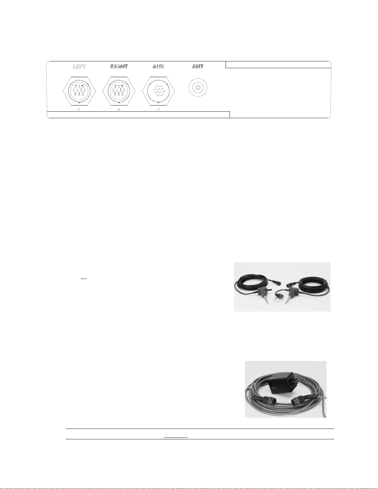
Figure 1 PT-210M Processor/Transmitter
2.0 PT-210 Hardware Overview
The PT-210M is a multi-purpose processing unit, designed to accept up to four sensor inputs; one
seismic, two inputs for either magnetic or passive infrared, and a switch closure input. These
inputs may be used either singularly, in any combination, or all at the same time. The following
paragraphs describe the different types of sensors that may be used with the PT-210M.
2.1 Sensors
2.1.1 Seismic
The seismic sensor may be installed into either the
Left or Right input of the PT-210M. A special "Y"
adapter cable may be used to connect seismic when
two additional sensors (Magnetic or PIR) are
connected to the left and right inputs. The seismic
input may also be used with multiple seismic sensors
connected together to form a string.
2.1.2 Magnetic
The magnetic sensor(s) may be connected to the Left
and/or Right inputs of the PT-210M. If two sensors are
used, the PT-210M may be configured to either report
single detections or directional detections. If both left
and right inputs are to be used for infrared and/or
magnetic, a special "Y" adapter cable may be used to also
connect seismic to one of the inputs.
Note:
A single magnetic sensor may not be used to detect directional travel.
Page 7
4 PB-007726 Rev - A
2005.07.04
2.1.3 Passive Infrared
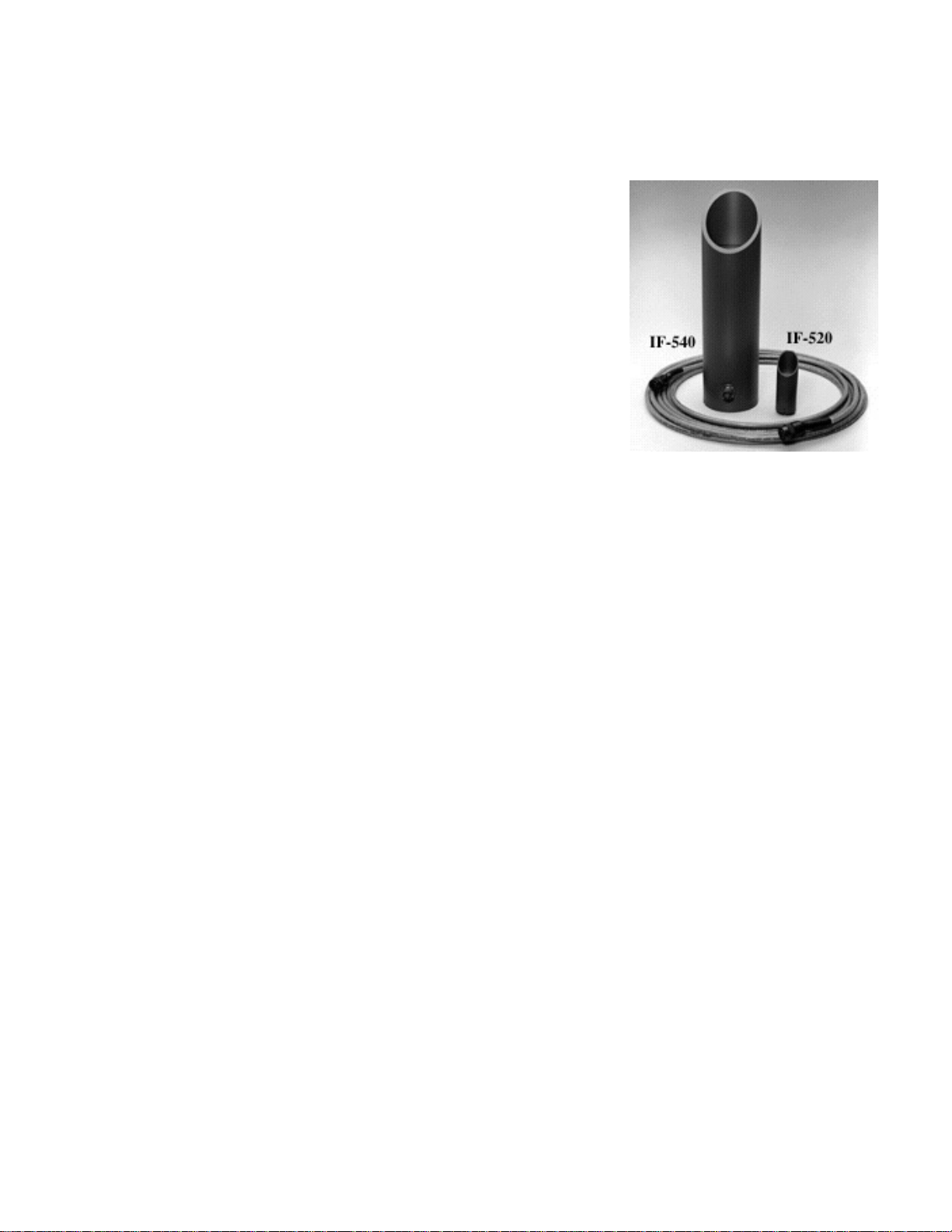
The two inputs marked Left and Right may also be used
for passive infrared (PIR) sensors. Each PIR sensor
contains two sensing elements, which enable the user to
deploy them in the following configurations:
In the single Left\Right mode, each sensor is programmed
to report a specific event when that sensor is triggered. The
user then knows which individual sensor was triggered.
Alternatively, the PT-210M may be programmed in the
Directional mode. In this mode, the PT-210M determines
the target’s direction of travel and reports the direction as a
specific event. Direction may be determined by using two
PIR sensors, or a single PIR sensor. Long range (IF-540)
and short range (IF-520) models are available.
2.1.3.1 Two PIR Sensor Deployment
Two PIR sensors may be connected, one to the L (left) and one to the R (right)
input connectors, in which case only one element in each PIR sensor is utilized.
2.1.3.2 Single Sensor Deployment
A single PIR sensor may also be used for direction sensing. The cable can connect
to the Right or Left input connector, and users must select the "One Sensor"
option with the software or programmer.
2.1.4 Contact Sensor
Any sensor that provides a switch open or switch closure may be used to trigger an alarm
transmission by the PT-210M. Sensors such as a pressure mat, trip wire, or active
infrared may be utilized. Connect pin "J" of the AUX connector to the switch of the
external device and pin "G" of the AUX connector to ground.
Page 8

5 PB-007726 Rev - A
2005.07.04
2.2 Camera Trigger
The PT-210M has the ability to provide the user with an external camera trigger. The
trigger is activated each time a detection occurs. The camera trigger circuit provides the
user with an interface between the PT-210M and an externally connected device (i.e.
relay, still camera or video camera.) When the camera trigger is activated, a switch-toground is closed for the user-selected time period – 0 to 1.5 seconds in 50 millisecond
increments.
The camera trigger exits the PT-210M through the "A" pin of the auxiliary "AUX"
connector and pin "G" is ground.
2.3 Communications
Communications operations are conducted through the AUX connector using a separate
Smart Cable (part# WI001615-003) connected to either a desktop PC computer or a
PDA-4000 Handheld PRogrammer
2.4 Antenna
The supplied stainless steel 1/4 wave right-angle whip antenna attaches to the TNC
connector on the PT-210M.
2.5 Power Source
2.5.1 Primary Source
The PT-210M's flexibility allows for use of a variety of DC battery power sources to
supply the unit. If a custom power source is used, it must adequately supply a +9 to +15
volt DC source with capacity rated for the operational life desired.
The standard power source is an 8 cell, 9 volt alkaline battery pack, (EN22 or equivalent)
contained within an integral battery compartment A battery pack comprised of three Dcell lithium batteries may be substituted for use in extreme cold deployments.
There is no ON/OFF switch on the PT-210M. The unit is operational upon connection of
the power source and sensors.
Page 9
6 PB-007726 Rev - A
2005.07.04
2.5.2 Secondary Source
An additional power source supplying +12 volts DC +/-12% may be connected externally
to the "AUX" connector. Connect pin "C" on the "AUX" connector to the + voltage and
pin "G" to ground.
3.0 PT-210 PC Configuration Software
3.1 Software Installation
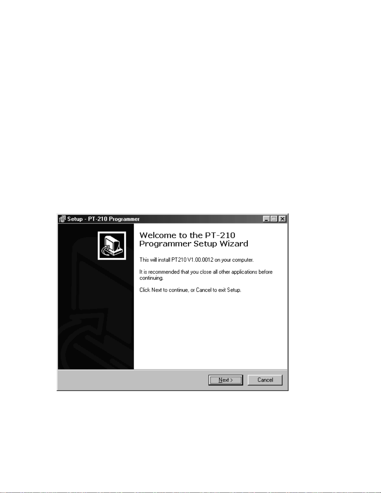
1. Insert the EIDS Product Programming CD into the CD-ROM drive.
2. The CD should begin automatically, which will begin the setup/installation process. If
the CD does not begin automatically, select
START/RUN
and enter D:/setup (where D:
represents the drive letter assigned to the CD-ROM drive) and click OK.
3. Follow the instructions on the screen. Click Next to continue through the Setup process.
4. The PT-210 program may be launched upon completion of installation.
Page 10
7 PB-007726 Rev - A
2005.07.04
Menu Bar
Speed Bar
3.2 Using the Software
Programming
Parameters
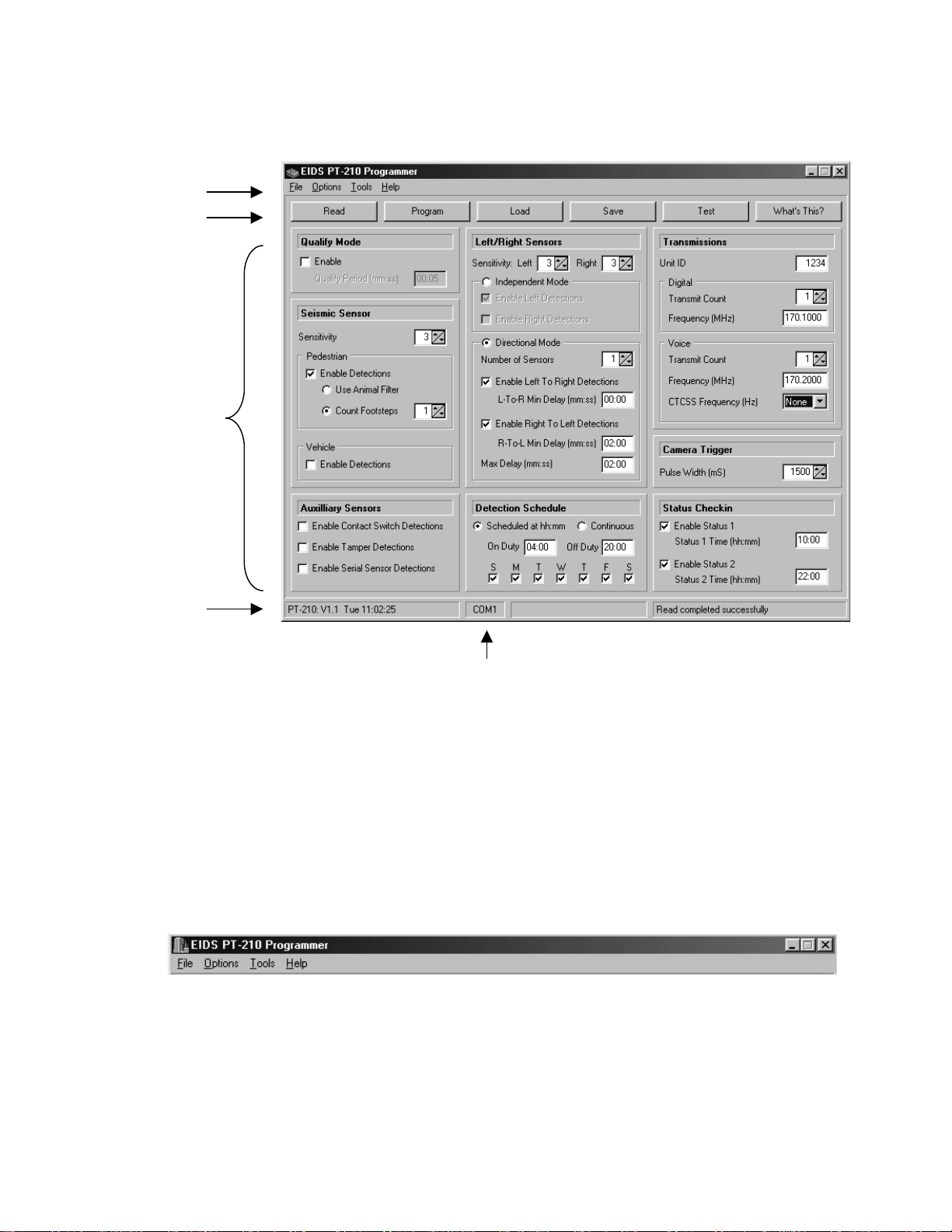
The software is navigated via four distinct sections:
• Menu Bar
• Speed Bar
• Programming Parameters
• Status Bar
3.3 Menu Bar
The “File” selection located on the Menu Bar provides access to familiar functions such
as Load, Save, Print, and Exit. Under “Options”, the communication port and reminder
preferences may be selected. The
“Tools”
menu provides access to inhibit times and
other seldom used features.
“Help”
provides access to a variety of program specific
topics contained within the program.
Status Bar
Selected Com Port
Page 11
8 PB-007726 Rev - A
2005.07.04
3.3.1 File Selection
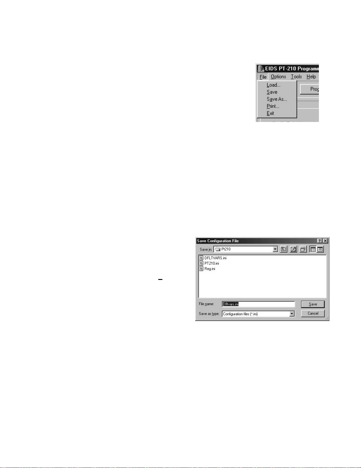
3.3.1.1 Load
Select Load from the File list to retrieve previously
saved parameters (adjustments). This function displays
saved setup files available for retrieval. Clicking load
opens a browser window to locate and retrieve the saved
configuration file (xxxxx.ini).
3.3.1.2 Save
Use this menu command when you want to save the current parameters to a PT210M configuration file. The first time you use this menu command, the Save
Configuration File dialog will be invoked so you can specify the proper folder
and file. Thereafter, when using this menu command, the current configuration
will simply be saved to the specified configuration file.
3.3.1.3 Save As
To save a configuration file in a
different folder, select Save As from
the File list, then locate and open the
desired folder. In the File name box,
type a descriptive name for the file
and then click
Save
. To overwrite
the program’s default parameters,
Save as file name “DFLTVARS.ini”.
3.3.1.4 Print
Use this menu command to print the current parameters to a local or network
printer. When you use this menu command, the Print dialog will be invoked so
you can specify the desired printer and number of copies.
Page 12

9 PB-007726 Rev - A
2005.07.04
3.3.1.5 Exit
Select Exit to close the program. A prompt may appear requesting to save the
current configuration file before closing. The save prompt may be disabled under
the Option list / Reminders.
3.3.2 Options Selection
3.3.2.1 Reminders
Use this menu command to open the Reminders Setup dialog. New users may
find the reminders helpful in pointing out subtle program features or situations
that should be avoided. Experienced users may wish to turn off one or more of
the reminders. The Reminders Setup dialog provides a convenient location where
all reminders are listed and can be individually enabled or disabled.
A check mark indicates the Reminder is active. Reminders appear as a Pop-Up
dialog box during selected operations. Checking “Don’t remind me again” in a
dialog box disables future reminders.
3.3.2.2 Show Splash
This menu item toggles the enable status of the program splash dialog. If
checked, the splash dialog will display during program initialization.
3.3.2.3 Com Port Setup
Use this menu command to open the COM Port Setup Dialog. This program
requires an asynchronous serial communications (COM) port in order to interface
with the PT-210M. Since many computers are equipped with multiple COM
ports, the COM Port Setup dialog is provided to allow you to select the COM port
you wish to use.
Note: If your computer is not equipped with a COM port, but is USB equipped
(common with many laptop computers), you will need to purchase a USB to
Serial RS-232 adapter.
Page 13
10 PB-007726 Rev - A
2005.07.04
3.3.3 Tools Selection
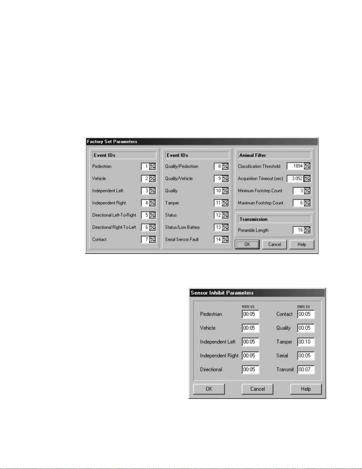
3.3.3.1 Factory Set Parameters
Factory Set Parameters are informational only. Factory authorization is required
for adjustment. This information is valuable to PT-210M users when Voice
Transmissions are enabled. The ID numbers assigned to the various sensors and
internally generated alarms are displayed. When a voice transmission is received,
the Message ID Number correlates to the following table:
3.3.3.2 Sensor Inhibit Parameters
The
Inhibit Parameters
specify a
shutdown period where the
sensor circuits
are
desensitized
immediately prior to a message
transmission, and remain
desensitized for the selected
amount of time after the end of
transmission.
The Inhibit period allows the RF
transmission energy to dissipate,
preventing false detections
caused by potential feedback
through the sensitive detection
processing circuit.
Page 14

11 PB-007726 Rev - A
2005.07.04
The minimum 5-second value is adequate for Sensor Inhibit settings. A minimum
7 seconds value is recommended for the Transmit Inhibit. In some instances, a
longer inhibit time may be desired to reduce transmissions in areas which
experience high levels of activity.
3.3.3.3 System Information
Displays System Information with no user adjustable parameters. Used for factory
diagnostics only.
3.3.4 Help Selection
3.3.4.1 Contents
Displays the contents of help files with links to the specific subject matter.
3.3.4.2 Enter Day Pass
A factory technician may issue a Day Pass to unlock diagnostic software utilities
for remote troubleshooting. The Day pass enables the Factory Support Mode,
valid for the remainder of the current day. Enter the supplied Day Pass number
using this menu option. Exiting the software will not cancel Factory Support
Mode.
3.3.4.3 About
Use this menu command to open the program About dialog. This dialog provides
program version information as well as e-mail and web contact information.
3.3.4.4 What’s This?
“What’s This” provides access to help topics associated with onscreen parameters. Clicking “What’s This” from the Help list
initiates a (?) question mark next to the pointer . When the
pointer is positioned over the text of an on-screen parameter and left
clicked, a dialog box appears with related help text. “What’s This” is also called
by positioning the cursor over the desired text and right clicking or selecting the
“What’s This” button on the Speed Bar.
Page 15

12 PB-007726 Rev - A
2005.07.04
3.4 Speed Bar
The Speed Bar provides quick access to commonly executed functions.
3.4.1 Read
The Read function establishes communication with the PT-210M and uploads the current
programmed parameters stored in the PT-210M and displays them on-screen. To perform
a Read, connect the separate computer interface Smart Cable (part# WI001615-003) and
a
power source
to the PT-210M connector. Click
Read
to import and display the current
PT-210M programmed settings. The Status Bar indicates the communication progress.
Note: It is necessary to perform a ‘READ” prior to modifying the on-screen parameters to
identify the configuration of the PT-210M hardware.
3.4.2 Program
Click Program to download the on-screen configuration parameters to the PT-210M. The
Status Bar indicates the communication progress and any errors that may have occurred.
3.4.3 Load
A previously saved configuration file may be retrieved using the Load function. Select
Load and navigate using the browser window to locate the desired configuration file.
3.4.4 Save
To save a configuration file in a different folder, select Save As from the File list, then
locate and open the desired folder. In the File name box, type a descriptive name for the
file then click Save. To overwrite the programs default parameters, Save as file name
“DFLTVARS.ini”.
3.4.5 Test
The
Transmit Test Mode
initiates a test transmission upon command when a computer
is connected to the PT-210M. The transmission sent is the Unit ID number with the
message “Status”.
Page 16
13 PB-007726 Rev - A
2005.07.04
3.4.6 What’s this?
“What’s This” provides access to help topics associated with on-screen
parameters. Clicking the “What’s This” button on the Speed Bar initiates a
(?) question mark next to the cursor . When the cursor is hovered over the
text of an on-screen parameter and left clicked, a dialog box appears with
related help text. “What’s This” is also called by positioning the cursor over the desired
text and right clicking or selecting “What’s This” from the Help list in the Menu Bar.
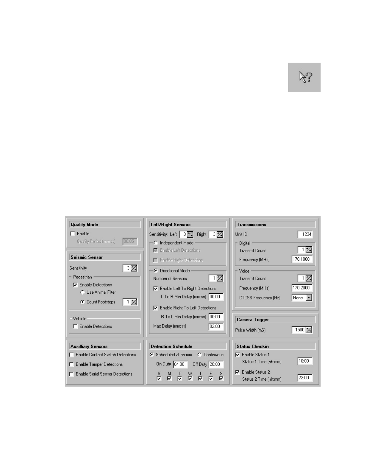
3.5 Programming Parameters
Programming Parameters are the variables that define the operation of the PT-210M. These
parameters are read and programmed into the PT-210M’s microprocessor. The PT-210M
software groups the variables into the following topics:
Qualify Mode Left/Right Sensors Transmissions
Seismic Detection Schedule Camera Trigger
Auxiliary Sensors Status Check in
Page 17
14 PB-007726 Rev - A
2005.07.04
3.5.1 Qualify Mode
In Qualify Mode, two physically different sensors must be triggered within the Qualify
Period before a qualify event will be transmitted. Eligible sensors are Seismic (Pedestrian
and Vehicle), Left, Right, Contact, and Serial. Check the enable box to activate Qualify
Mode.
Note: If a Seismic/Pedestrian detection is involved, the event transmitted will be
QUAL/PEDESTRIAN. If a Seismic/Vehicle detection is involved, the event transmitted
will be QUAL/VEHICLE. With all other combinations, the event transmitted will be
simply QUAL.
3.5.1.1 Qualify Period
When Qualify Mode is enabled, select the Qualify Time Period within which
two physically different sensors must trigger to generate a detection message.
The Qualify Period starts when the system is in Qualify Mode and activity is
detected on an enabled sensor. Before the Qualify Period expires, a detection must
occur on another (physically different) sensor in order for the qualify event to be
transmitted. The valid range for this parameter is 00:01 to 59:59 (minutes and
seconds).
3.5.2 Seismic Sensor Setup
3.5.2.1 Seismic Sensitivity
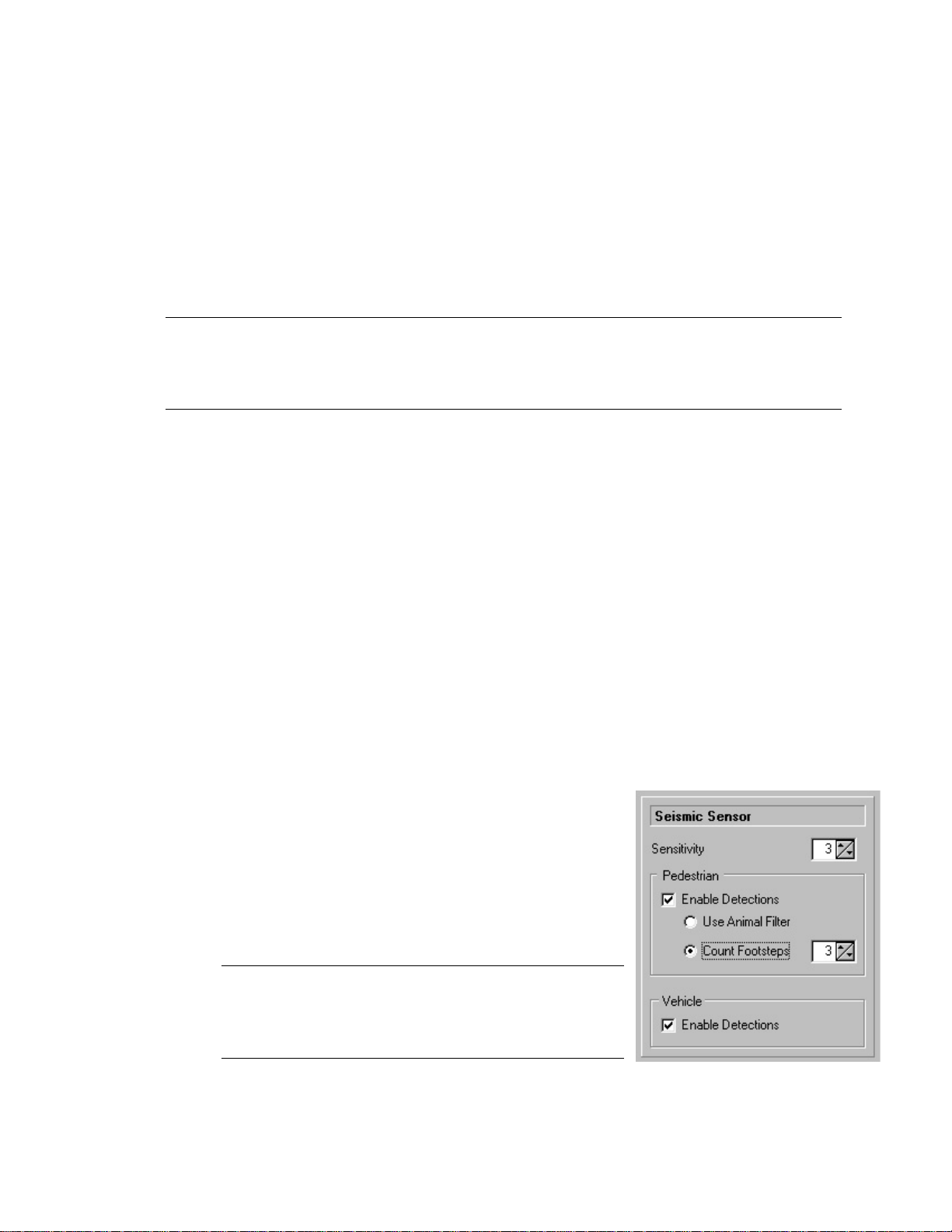
The Seismic Sensitivity control is used to adjust the
sensitivity of the SEISMIC (Pedestrian/Vehicle)
sensor. The sensitivity is adjustable from 1 (least
sensitive) to 5 (most sensitive). This setting is only
available when Pedestrian or Vehicle Detections are
enabled.
Note:
A setting of 3 is satisfactory for most
installations. Also note that high settings can trigger
false detections. Therefore, set the sensitivity only as
high as necessary to obtain the required coverage.
Page 18

15 PB-007726 Rev - A
2005.07.04
If this control is unchecked, Seismic/Pedestrian detections will be ignored. If
checked, detections will be processed based on the PT-210M operating mode:
Qualify Mode off: The PEDESTRIAN event code will be transmitted.
Qualify Mode on: The QUAL/PEDESTRIAN event code will be transmitted.
3.5.2.2 Use Animal Filter
If this control is checked, Seismic/Pedestrian activity will be processed through an
Animal Filter program. The program distinguishes human activity from animal
activity based on time between footsteps. If the Animal Filter determines that an
animal has caused the activity, the detection will be ignored.
Note: When the animal filter is turned on, a group of pedestrians may produce a
signature similar to that of four legged animals, causing the activity to be ignored.
In areas where group pedestrian traffic is anticipated, the animal filter should be
turned off.
3.5.2.3 Count Footsteps
If this control is checked, the Animal Filter will be disabled and
Seismic/Pedestrian activity will be processed using a simple counter. When using
this method, a 5-second timer is started when the first footstep is detected. If a
sufficient number of steps are detected before the timer expires, a PEDESTRIAN
event is transmitted. If the number of steps is insufficient and the timer expires,
the mechanism resets. The number of footsteps required for an event is set with
the adjacent control.
3.5.2.4 Enable Vehicle Detections
If this control is unchecked, Seismic/Vehicle detections will be ignored. If
checked, detections will be processed based on the PT-210M operating mode:
Qualify Mode off: The VEHICLE event code will be transmitted.
Qualify Mode on: The QUAL/VEHICLE event code will be transmitted.
Page 19

16 PB-007726 Rev - A
2005.07.04
3.5.3 Auxiliary Sensor Setup
3.5.3.1 Enable Contact Switch Detections
If this control is unchecked, Contact Switch detections will be ignored. If
checked, detections will be processed based on the PT-210M operating mode:
Qualify Mode off: The CONTACT event code will be transmitted.
Qualify Mode on: A qualified detection will transmit the QUAL event code.
If a SEISMIC detection is involved, QUAL/VEHICLE or QUAL/PEDESTRIAN
event codes will be transmitted
3.5.3.2 Enable Tamper Detections
If this control is unchecked, cable tamper and motion tamper detections will be
ignored. If checked, TAMPER events will be processed. If Voice transmissions
are enabled (transmit count > 0), the TAMPER event code will be transmitted
using synthesized voice 3 times, overriding a transmit count of 1 or 2. If Digital
transmissions are enabled (transmit count > 0), the TAMPER event code will be
transmitted using the EIDS digital format 3 times, overriding a transmit count of 1
or 2.
3.5.3.3 Enable Serial Sensor Detections (Optional)
If this control is unchecked, Serial Sensor detections will be ignored. If checked,
an event code in the range 33 to 63 will be transmitted. The event code is
application specific and requires custom programming of the serial sensor module
prior to deployment. If checked and custom programming has been performed,
detections will be processed based on the PT-210M operating mode:
Qualify Mode off: The SERIAL event code will be transmitted.
Qualify Mode on: A qualified detection will transmit the QUAL event code.
If a SEISMIC detection is involved, QUAL/VEHICLE or QUAL/PEDESTRIAN
event codes will be transmitted
Note:
The serial sensor module monitors the incoming battery supply voltage. If
the battery voltage is interrupted, the serial sensor module will initiate a series of 3
BATT FAULT transmissions. The transmission of this event cannot be disabled.
Page 20
17 PB-007726 Rev - A
2005.07.04
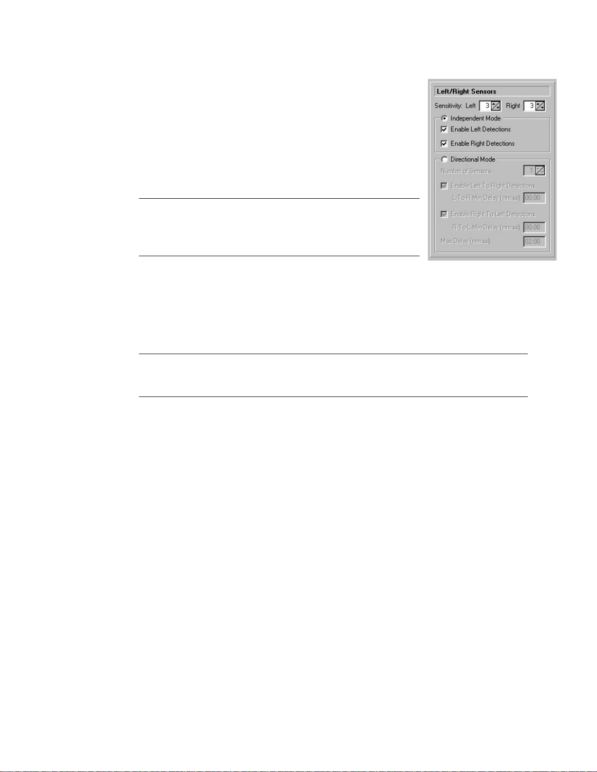
3.5.4 Left/Right Sensors
3.5.4.1 Left Sensor Sensitivity
The Left Sensitivity control is used to adjust the sensitivity
of the LEFT sensor. The sensitivity is adjustable from 1
(least sensitive) to 5 (most sensitive).
Note: A setting of 4 is satisfactory for most installations.
High settings can trigger false detections. Set the
sensitivity only as high as necessary to obtain the required
coverage.
3.5.4.2 Right Sensor Sensitivity
The Right Sensitivity control is used to adjust the sensitivity of the RIGHT sensor.
The sensitivity is adjustable from 1 (least sensitive) to 5 (most sensitive).
Note: A setting of 4 is satisfactory for most installations. High settings can
trigger false detections. Set the sensitivity only as high as necessary to obtain the
required coverage.
3.5.4.3 Independent
When the
Independent
button is checked, the LEFT and RIGHT sensors are
available for use independent of each other. To use Left or Right Sensors in
Qualify Mode, independent mode must be selected.
3.5.4.4 Enable Left Detections
If unchecked, Left sensor (Passive Infrared or Magnetic) detections will be
ignored. When checked, detections will be processed based on the PT-210M
operating mode.
Qualify Mode off: The LEFT event code will be transmitted.
Qualify Mode on: A qualified detection will transmit the QUAL event code.
If a SEISMIC detection is involved, QUAL/VEHICLE or QUAL/PEDESTRIAN
event codes will be transmitted.
Page 21
18 PB-007726 Rev - A
2005.07.04
3.5.4.5 Enable Right Detections
If this control is unchecked, Right sensor (Passive Infrared or Magnetic)
detections will be ignored. When checked, detections will be processed based on
the PT-210M operating mode:
Qualify Mode off: The RIGHT event code will be transmitted.
Qualify Mode on: A qualified detection will transmit the QUAL event code.
If a SEISMIC detection is involved, QUAL/VEHICLE or QUAL/PEDESTRIAN
event codes will be transmitted.
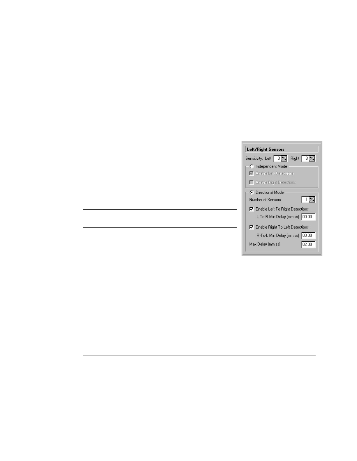
3.5.4.6 Directional Mode
When the Directional Mode button is checked, the
LEFT and RIGHT sensors are configured to work
together, allowing activity from left-to-right or rightto-left to be detected.
Note: This mode of service is not available when
Qualify mode is enabled.
3.5.4.7 Number of Sensors
When using Passive Infrared sensors in Directional Mode, you have the option of
using either 1 or 2 physical sensors. Directional mode using a single IF-520 or
IF-540 is possible because the passive infrared sensor contains two sensing
elements each producing a field of view. However, with one sensor, the angle of
the dead zone separating the two fields of view is rather narrow (approximately 3
degrees). To increase deployment flexibility, the use of two sensors is
recommended. When using a single sensor in directional mode, select 1. When
using two sensors in directional mode, select 2.
Note: The selection of one or two sensors applies to Passive Infrared sensors only.
Magnetic sensors must be used in pairs.
3.5.4.8 Enable Left-To-Right Detections
If this control is unchecked, left-to-right detections will be ignored. When
checked, left-to-right detections will be processed within the limits imposed by
Left-To-Right Minimum Delay and Directional Maximum Delay.
Page 22

19 PB-007726 Rev - A
2005.07.04
3.5.4.9 Left-To-Right Minimum Delay
This is the minimum time period permissible between left and right detections.
Detections that occur at a time interval less than the specified minimum time will
be ignored. The valid range for this period is 00:00 to 04:59 (minutes and
seconds). This delay must be less than the Directional Maximum Delay. A
Minimum Delay is useful to detect slow moving objects within a monitored area.
3.5.4.10 Enable Right-To-Left Detections
If this control is unchecked, right-to-left detections will be ignored. When
checked, right-to-left detections will be processed within the limits imposed by
Right-To-Left Minimum Delay and Directional Maximum Delay.
3.5.4.11 Right-To-Left Minimum Delay
This is the minimum time period permissible between right and left detections.
Detections that occur at a time interval less than the specified minimum time will
be ignored. The valid range for this period is 00:00 to 04:59 (minutes and
seconds). This delay must be less than the Directional Maximum Delay. A
Minimum Delay is useful to detect slow moving objects within a monitored area.
3.5.4.12 Directional Maximum Delay
This is the maximum time period permissible between detections from the left and
right sensors. Detections that occur at a time interval greater than the specified
maximum time will be ignored. The valid range for this period is 00:00 to 5:00
(minutes and seconds). This delay must be greater than the Left-To-Right
Minimum Delay and/or the Right-To-Left Minimum Delay. A Maximum Delay is
useful to detect fast moving objects within a monitored area.
Page 23

20 PB-007726 Rev - A
2005.07.04
3.5.5 Detection Schedule
3.5.5.1 Scheduled Detection Mode
If this control is checked, the PT-210M will be “On Duty” (processing sensor
detections) only from the “On Duty” time to the “Off Duty” time on the days
specified.
3.5.5.2 Continuous Detection Mode
If this control is checked, the PT-210M will be “On Duty” (processing sensor
detections) at all times.
3.5.5.3 On Duty Time
The On Duty time is used only with the
Scheduled Detection Mode. This is the time of
day the PT-210M will begin processing sensor
detections and is programmable from 00:01 to
23:59 (hours and minutes).
Note: The On Duty Time cannot be the same as the Off Duty Time, Status 1
Time, or Status 2 time.
3.5.5.4 Off Duty Time
The Off Duty time is used only with the Scheduled Detection Mode. This is the
time of day the PT-210M will stop processing sensor detections and is
programmable from 00:01 to 23:59 (hours and minutes).
Note: The Off Duty Time cannot be the same as the On Duty Time, Status 1
Time, or Status 2 Time.
Page 24
21 PB-007726 Rev - A
2005.07.04
3.5.5.5 Detection Days Of The Week
When in Scheduled Detection Mode, the PT-210M can be programmed to process
sensor activity on any desired day(s) of the week. To enable the PT-210M to go
“On Duty” and process sensor detections, check the desired day(s) of the week.
On days that are unchecked, the PT-210M will remain “Off Duty” when the On
Duty time arrives.
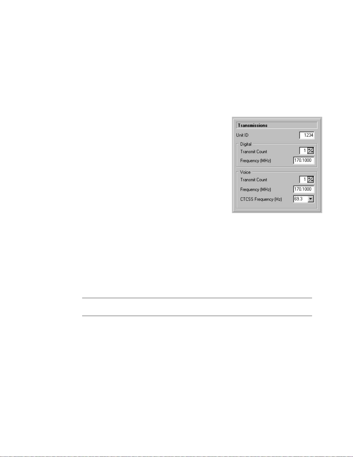
3.5.6 Transmissions
The PT-210M can transmit events using a digital format,
voice format, or both as determined by the respective
transmit count.
3.5.6.1 Unit ID
The Unit ID establishes the PT-210M’s identity.
All PT-210M transmissions contain the Unit ID as
well as other information to describe the nature of
the event. The Unit ID valid range is 0 to 8175.
3.5.6.2 Digital Transmit Count
The Digital Transmit Count establishes the number of times a message will be
transmitted using the EIDS digital format. The count is programmable from 0 to
3. If the Digital Transmit Count is set to 0, the PT-210M will not transmit a
digital message.
Note: If the Digital Transmit Count is greater than 0, and a Tamper detection
occurs, the Tamper event will be transmitted 3 times.
3.5.6.3 Digital Transmit Frequency
The Digital Transmit Frequency is used for transmitting messages in the EIDS
digital message format. The PT-210M frequency range is set at the factory and is
displayed following a read of the unit.
Page 25

22 PB-007726 Rev - A
2005.07.04
Available PT-210M frequencies are selected by clicking on the drop-down list
control and left clicking the desired frequency. The PT-210M unit cannot
transmit on any other frequency other than the specific ones shown.
Note: If both digital and voice transmissions are desired, the user may elect to
transmit on the same or different frequencies.
3.5.6.4 Voice Transmit Count
The Voice Transmit Count establishes the number of times a message will be
transmitted using the synthesized voice format. The count is programmable from
0 to 3. If the Voice Transmit Count is set to 0, the PT-210M will not transmit a
voice message.
Note: If the Voice Transmit Count is greater than 0, and a Tamper detection
occurs, the Tamper event will be transmitted 3 times.
3.5.6.5 Voice Transmit Frequency
The Voice Transmit Frequency is used for transmitting messages in the
synthesized voice format. The PT-210M frequency range is set at the factory and
is displayed following a read of the unit. Available PT-210M frequencies are
selectable by clicking on the drop-down list control and left clicking the desired
frequency. The PT-210M unit cannot transmit on any other frequency other than
the specific ones shown.
Note: If both digital and voice transmissions are desired, the user may elect to
transmit on the same or different frequencies.
3.5.6.6 CTCSS Frequency
When voice transmissions are enabled, the PT-210M supports the addition of a
CTCSS (Continuous Tone Coded Squelch System) tone. To enable CTCSS,
select the desired tone frequency from the drop-down list control. To disable
CTCSS, select “None”.
Page 26
23 PB-007726 Rev - A
2005.07.04
3.5.6.7 Camera Trigger Pulse Width
Prior to transmitting a sensor event, the PT-210M can activate a camera trigger
output. The camera trigger output produces a momentary connection to ground,
often used to trigger an externally connected device (i.e. relay, still camera, or
video camera.) The camera trigger pulse width is adjustable from 0 to 1.5 seconds
in 50 millisecond increments.
Note: The camera trigger is NOT activated when transmitting a Status 1 or Status
2 event.
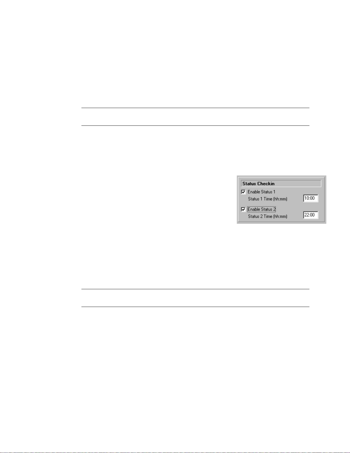
3.5.7 Status Check in
3.5.7.1 Enable Status 1
The PT-210M provides the ability to send up to 2
status transmissions per day. Status transmissions are
sent to indicate to the recipient that the PT-210M is
operational and that the transmission is properly
generated and received. If the Enable Status 1
checkbox is checked, Status 1 transmissions will
occur each day at the time specified by Status 1 Time.
3.5.7.2 Status 1 Time
This is the time of day at which a Status 1 transmission will occur and is
programmable from 00:01 to 23:59 (hours and minutes).
Note: The Status 1 Time cannot be the same as the On Duty Time, Off Duty
Time, or Status 2 Time.
3.5.7.3 Enable Status 2
The PT-210M provides the ability to send up to 2 status transmissions per day.
Status transmissions are sent to indicate to the recipient that the PT-210M is
operational and that the transmission is properly generated and received. If the
Enable Status 2 checkbox is checked, Status 2 transmissions will occur each day
at the time specified by Status 2 Time.
Page 27
24 PB-007726 Rev - A
2005.07.04
3.5.7.4 Status 2 Time
This is the time of day at which a Status 2 transmission will occur and is
programmable from 00:01 to 23:59 (hours and minutes).
Note: The Status 2 Time cannot be the same as the On Duty Time, Off Duty
Time, or Status 1 Time.
3.6 Status Bar
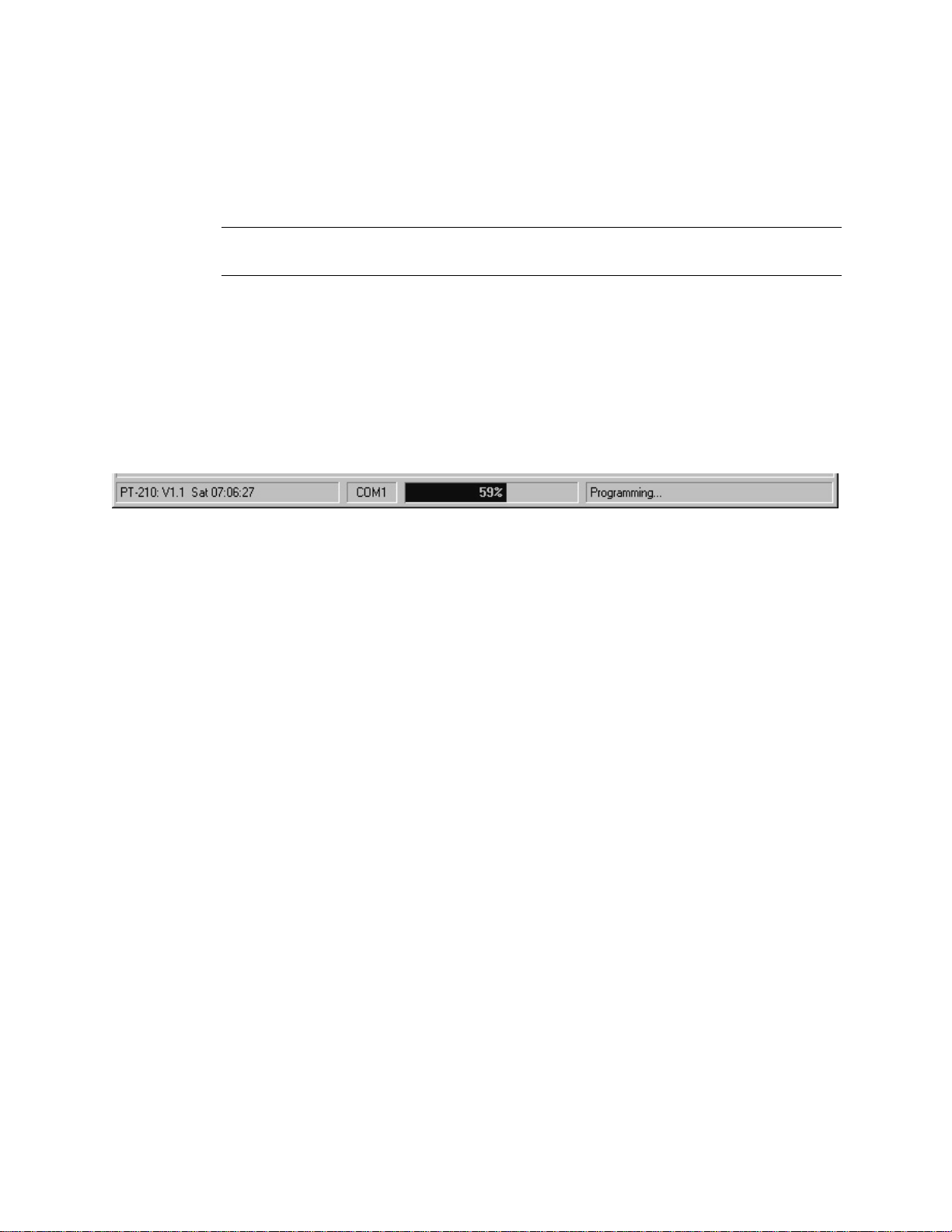
The Status Bar displayed at the bottom of the screen provides confirmation and software status
information. The lower left corner is blank until a read is performed. Following a read, the PT210M firmware version, day of week, and time of day are displayed.
The selected COM port and an operations progress bar are displayed in the center.
In the lower right corner the following messages may be displayed:
1. Timed out while waiting for PT-210M response 7. Read error: Operation aborted
2. Configuration file load unsuccessful 8. Read completed successfully
3. Configuration file load successful 9. Programming error: Operation aborted
4. Configuration file load canceled 10. Programming complete
5. Configuration file save successful 11. Verification error: Operation aborted.
6. Configuration file save canceled 12. Verification completed successfully
4.0 PT-210 PDA Software
4.1 Using the software
The PT-210M PDA software comes pre-loaded into the PDA-4000 Handheld Programmer and
therefore no installation is required. Turn the unit on by pressing the power button, located in the
lower right-hand corner of the TDS Recon Pocket PC keypad, briefly. Afterwards, a Windows
Pocket PC desktop screen appears. Tap the
START
button in the upper right-hand corner of
the screen and select EIDS from the drop down list menu. Once the EIDS Product Programmer
begins, select PT-210 from the Product Model menu and tap OK to launch the configuration
software.
Page 28

25 PB-007726 Rev - A
2005.07.04
4.2 Using the Software
Once the PT-210 program is launched, a configuration screen will appear on the display. The
configuration screen provides quick access to configuration components and also allows the
operator to review configuration settings prior to programming operations.
The configuration screen contains three distinct sections:
• Input Selector
• Menu Bar
• Programming Parameters
4.3 Input Selector
In the lower right-hand corner of the configuration screen is an up-arrow icon. Tapping the uparrow icon produces a pop-up menu list displaying available character input methods. This menu
allows the operator to change and alter the input method for the PT-210 configuration screen.
Once the input method has been selected, the icon next to the up-arrow icon will change to
reflect the selection. Tapping this icon will invoke the selected input method.
The recommended input method for the PT-210M configuration screen is keyboard. This
method produces a virtual keyboard that resembles a typical PC keyboard and is used for entering
alpha-numeric data into various fields within the configuration screen.
For specific information on the other types of input methods, please refer to the TDS Recon
manual.
4.4 Menu Bar
The Menu Bar is located along the bottom of the configuration screen and consists of the
selections File, View, Unit, and Help.
The “File” selection provides access to familiar functions such as New, Open, Save, Save As and
Exit. Under “
View
”, the configuration settings may be displayed or suppressed. The
“Unit”
menu provides access to various device communication commands and test features. “Help”
provides access to a variety of program specific topics contained within the program as well as
program version information.
Page 29

26 PB-007726 Rev - A
2005.07.04
4.4.1 File Selection
4.4.1.1 New
Selecting New from the File list will return the operator to the EIDS Product
Programmer product model screen. This allows a new product model to be
selected and configured.
4.4.1.2 Open
The Open command allows the operator to access and open a saved Telonics
Parameter File and import it into the program for use. File details such as name,
location, and last modified are displayed.
4.4.1.3 Save
Use this menu command when you want to save the current parameters to a
Telonics Parameter File. The first time you use this menu command, the Save As
dialog will be invoked so you can specify the proper folder and file. Thereafter,
when using this menu command, the current configuration will simply be saved to
the specified configuration file.
4.4.1.4 Save As
To save a configuration file in a folder different from the default location, select
Save As
from the
File
list, then locate and open the desired folder. In the
Name
box, type a descriptive name for the file and then tap OK.
4.4.1.5 Exit
Select Exit to close the program. A prompt may appear requesting to save the
current configuration file before closing.
Page 30

27 PB-007726 Rev - A
2005.07.04
4.4.2 View
4.4.2.1 Show Values
This menu item allows the operator to view all of the configuration data at once.
The settings of each configuration item are displayed on the screen for reviewing
and referencing during the course of the configuration process.
4.4.2.2 Hide Values
This menu item hides the configuration data and only displays the individual
configuration headings. This allows for speedy access to specific items during the
configuration process.
Note: A check mark will indicate the item selected.
4.4.3 Unit
4.4.3.1 Check Connection to Unit
Use this menu command to verify the communication link between the PDA-4000
Handheld Programmer and the PT-210M Processor/Transmitter.
4.4.3.2 Program Parameters
This menu command initiates the programming process. When there have been
changes made to the configuration screen, use this command to download the
system time and the new configuration settings from the PDA-4000 into the PT210M.
Note:
No configuration changes take effect until the Program Parameters
operation has been completed
Page 31

28 PB-007726 Rev - A
2005.07.04
4.4.3.3 Read Parameters
Use this menu command to establish communications with the PT-210M and
upload programmed configuration data into the PDA-4000. To perform a Read,
connect the separate computer interface Smart Cable (part# WI001615-003) and
a power source to the PT-210M connector. Click Read to import and display the
current PT-210M programmed settings.After “reading” the unit, the configuration
data is displayed on the configuration screen for review and modification if
necessary.
Note: It is necessary to perform a ‘READ” prior to modifying the on-screen
parameters to identify the configuration of the PT-210M hardware.
4.4.3.4 Send Time to Unit
Use this menu command to download the system time only from the PDA-4000
into the PT-210M. When initiated, the current time in the PT-210M will be
replaced by the PDA-4000 time. Several configuration options for the PT-210M
are dependant upon time, so it is important to maintain the correct time.
4.4.3.5 Retrieve Time from Unit
This menu command obtains the current system time from the PT-210M.
4.4.3.6 Perform Test Transmission
Use this menu command to initiate a test transmission from the PT-210M. This
action is oftened performed to verify system performance and to verify
transmission and reception ability prior to and during deployment.
4.4.4 Help
4.4.4.1 Help
Use this menu command to access the integrated EIDS Help system. The system
is separated into categories designed to give the operator an overview of the
various configuration options. Help related to a specific topic is available later in
the program during the configuration operation.
Page 32

29 PB-007726 Rev - A
2005.07.04
4.4.4.2 About
This menu command displays a dialog containing program version and copyright
information. Contained also, is a listing of the installed authorization codes. If
there are no authorization codes installed, then the PT-210M configuration
software is operating in evaluation mode. This mode will persist for 30 days or
until a valid authorization code is installed.
To install an authorization code, tap the Add… button. This will produce a dialog
box prompting the operator to enter a code. Tap the keyboard input device icon
and enter the code by tapping the applicable characters. Tap OK when finished.
To delete an authorization code, select the code for deletion with the stylus and
then tap Delete. Tap OK when finished.
4.5 Programming Parameters
Programming Parameters are the variables that define the operation of the PT-210M. These
parameters are read and programmed into the PT-210M’s microprocessor. The PT-210 PDA
software groups the variables into the following topics:
•
Product Model
• Units
• Sensor Detection
• Directional Mode
• Transmitter
• Schedule
• Inhibit
4.5.1 Product Model
The Product Model section reverts the operator back to the product model screen. Tap
the Product Model message text or double-tap the Product Model contents field to
access the adjustment screen.
Select the desired product for evaluation and tap OK to enter the configuration screen for
the selected product. Tap Cancel to abort the process.
Tapping the
Help
button initiates the Product Model Selection help system. From the
menu bar the operator also has access to the EIDS Help contents and to the TDS Recon
help contents. A
Find
feature allows the operator to search for a particular item.
Page 33

30 PB-007726 Rev - A
2005.07.04
Note: The menu bar selections at the bottom of the configuration screen are not available
in this operation.
4.5.2 Units
The units section provides the operator with information about the different devices
which have been communicated with by the PDA-4000 programmer within a particular
product model during a particular configuration session. The serial number of the device,
the installed operating system (Firmware) and any factory parameters are listed in the
order in which they were accessed. Various editing features allow enhanced operability.
Tap the Units message text or double-tap the Units contents field to access the
adjustment screen.
When finished, tap OK to return to the configuration screen. Tap Cancel to abort the
process.
Tapping the Help button initiates the Units Section help system. From the menu bar the
operator also has access to the EIDS Help contents and to the TDS Recon help contents.
A Find feature allows the operator to search for a particular item.
Note: The menu bar selections at the bottom of the configuration screen are not available
in this operation.
4.5.3 Sensor Detection
The Sensor Detection section contains configuration items for all of the sensor
acitivities. This is where the individual sensors are enabled or disabled, various
sensitivity settings are adjusted and sensor modes of operation are established. Tap the
Sensor Detection message text or double-tap the Sensor Detection contents field to
access the adjustment screen.
4.5.3.1 Sensor Mode
The sensor mode field allows the user to select Not Qualified, Qualified, or
Directional
detection modes.
•
Not Qualified is the mode of operation where all of the sensors act
independently of each other and any single sensor can produce an alarm.
Page 34

31 PB-007726 Rev - A
2005.07.04
•
Qualified is the mode of operation where two physically different
sensors must act within the Qualify Period to produce an alarm. Eligible
sensors are Seismic (Pedestrian and Vehicle), Left, Right, Contact, and
Serial.
Note: If a Seismic/Pedestrian detection is involved, the event transmitted
will be QUAL/PEDESTRIAN. If a Seismic/Vehicle detection is involved,
the event transmitted will be QUAL/VEHICLE. With all other
combinations, the event transmitted will be simply QUAL.
• Directional is the mode of operation where two sensors act as a pair
allowing activity from left-to-right or right-to-left to be detected.
Alternatively, one single PIR sensor may be used in directional mode.
Note: This mode of service is not available when Qualify mode is enabled.
4.5.3.2 Qualify Period
In order to access this field, the Qualified selection must be made in the Sensor
Mode field above. The Qualify Period is the timeframe within which two
physically different sensors must trigger to generate a detection message.
The Qualify Period starts when activity is detected on an enabled sensor. Before
the Qualify Period expires, a detection must occur on another (physically
different) sensor in order for the event to be transmitted. The valid range for this
parameter is 00:01 to 59:59 (minutes and seconds). Enter the desired range using
the up and down arrows located next to the field box.
4.5.3.3 Sensors
This section is where specific sensors or specific functions are selected.
•
Seismic-Veh: If this control is unchecked, Seismic/Vehicle detections
will be ignored. If checked, detections will be processed based on the PT210M operating mode:
Qualify Mode off: The VEHICLE event code will be transmitted.
Qualify Mode on: The QUAL/VEHICLE event code will be transmitted.
Page 35

32 PB-007726 Rev - A
2005.07.04
• Seismic-Ped: If this control is unchecked, Seismic/Pedestrian detections
will be ignored. If checked, detections will be processed based on the PT210M operating mode:
Qualify Mode off: The PEDESTRIAN event code will be transmitted.
Qualify Mode on: The QUAL/PEDESTRIAN event code will be
transmitted.
Checking this selection also enables a drop down list menu containing the
Animal Filter and Footstep Counter. Tap the down arrow to view the
list and use the stylus to make the desired selection.
o Use Animal Filter: Seismic/Pedestrian activity will be processed
through an Animal Filter program. The program distinguishes
human activity from animal activity based on time between
footsteps. If the Animal Filter determines that an animal has
caused the activity, the detection will be ignored.
Note: When the animal filter is turned on, a group of pedestrians
may produce a signature similar to that of four legged animals,
causing the activity to be ignored. In areas where group pedestrian
traffic is anticipated, the animal filter should be turned off.
o Count “#” step(s): Seismic/Pedestrian activity will be processed
using a simple counter. When using this method, a 5-second timer
is started when the first footstep is detected. If a sufficient number
of steps are detected before the timer expires, a PEDESTRIAN
event is transmitted. If the number of steps is insufficient and the
timer expires, the mechanism resets. The number of footsteps
required for a detection is dependant upon the number of steps
selected in this field.
Note: Counting steps disables the Animal Filter
•
Left: If unchecked, Left sensor (Passive Infrared or Magnetic) detections
will be ignored. When checked, detections will be processed based on the
PT-210M operating mode.
Qualify Mode off: The LEFT event code will be transmitted.
Qualify Mode on: A qualified detection will transmit the QUAL event
code. If a SEISMIC detection is involved, QUAL/VEHICLE or
QUAL/PEDESTRIAN event codes will be transmitted.
Page 36

33 PB-007726 Rev - A
2005.07.04
• Right: If this control is unchecked, Right sensor (Passive Infrared or
Magnetic) detections will be ignored. When checked, detections will be
processed based on the PT-210M operating mode:
Qualify Mode off: The RIGHT event code will be transmitted.
Qualify Mode on: A qualified detection will transmit the QUAL event
code. If a SEISMIC detection is involved, QUAL/VEHICLE or
QUAL/PEDESTRIAN event codes will be transmitted.
• L-to-R: If this control is unchecked, left-to-right detections will be
ignored. When checked, left-to-right detections will be processed within
the limits imposed by Left-To-Right Minimum Delay and Directional
Maximum Delay featured in the Directional Mode configuration screen in
section 4.5.3.4.
Note: Though this field is accessible, the Directional mode must be
selected in the Sensor mode field in section 4.5.3.1.
• R-toL: If this control is unchecked, right-to-left detections will be
ignored. When checked, right-to-left detections will be processed within
the limits imposed by Right-To-Left Minimum Delay and Directional
Maximum Delay featured in the Directional Mode configuration screen in
setion 4.5.3.4.
Note: Though this field is accessible, the Directional mode must be
selected in the Sensor mode field in section 4.5.3.1.
• Serial: Serial sensor detections are only available on models that have
the serial sensor hardware installed.
If this control is unchecked, serial sensor detections will be ignored. If
checked, an event code in the range 33 to 63 will be transmitted. The
event code is application specific and requires custom programming of the
serial sensor module prior to deployment. If checked and custom
programming has been performed, detections will be processed based on
the PT-210M operating mode:
Qualify Mode off: The SERIAL event code will be transmitted.
Qualify Mode on: A qualified detection will transmit the QUAL event
code. If a SEISMIC detection is involved, QUAL/VEHICLE or
QUAL/PEDESTRIAN event codes will be transmitted
Page 37

34 PB-007726 Rev - A
2005.07.04
Note: The serial sensor module monitors the incoming battery supply
voltage. If the battery voltage is interrupted, the serial sensor module will
initiate a series of 3 BATT FAULT transmissions. The transmission of
this event cannot be disabled.
• Contact: If this control is unchecked, Contact Switch detections will be
ignored. If checked, detections will be processed based on the PT-210M
operating mode:
Qualify Mode off: The CONTACT event code will be transmitted.
Qualify Mode on: A qualified detection will transmit the QUAL event
code. If a SEISMIC detection is involved, QUAL/VEHICLE or
QUAL/PEDESTRIAN event codes will be transmitted
• Tamper: If this control is unchecked, cable tamper and motion tamper
detections will be ignored. If checked, TAMPER events will be
processed. If Voice transmissions are enabled, the TAMPER event code
will be transmitted using synthesized voice 3 times, overriding a transmit
count of 1 or 2. If Digital transmissions are enabled, the TAMPER event
code will be transmitted using the EIDS digital format 3 times, overriding
a transmit count of 1 or 2.
4.5.3.4 Seismic Sensitivity
The Seismic Sensitivity control is used to adjust the sensitivity of the SEISMIC
(Pedestrian/Vehicle) sensor. The sensitivity is adjustable from 1 (least sensitive)
to 5 (most sensitive). This setting is only available when Seismic-Veh or Seismic-
Ped detections are enabled.
Note:
A setting of 3 is satisfactory for most installations. Also note that high
settings can trigger false detections. Therefore, set the sensitivity only as high as
necessary to obtain the required coverage.
4.5.3.5 Left Sensitivity
The Left Sensitivity control is used to adjust the sensitivity of the LEFT sensor.
The sensitivity is adjustable from 1 (least sensitive) to 5 (most sensitive).
Note:
A setting of 4 is satisfactory for most installations. High settings can
trigger false detections. Set the sensitivity only as high as necessary to obtain the
required coverage.
Page 38

35 PB-007726 Rev - A
2005.07.04
4.5.3.6 Right Sensitivity
The Right Sensitivity control is used to adjust the sensitivity of the RIGHT sensor.
The sensitivity is adjustable from 1 (least sensitive) to 5 (most sensitive).
Note: A setting of 4 is satisfactory for most installations. High settings can
trigger false detections. Set the sensitivity only as high as necessary to obtain the
required coverage.
When finished, tap OK to return to the configuration screen. Tap Cancel to abort the
process.
Tapping the Help button initiates the PT-210 Sensor Detection Section help system.
From the menu bar the operator also has access to the EIDS Help contents and to the TDS
Recon help contents. A Find feature allows the operator to search for a particular item.
Note: The menu bar selections at the bottom of the configuration screen are not available
in this operation.
4.5.4 Directional Mode
The Directional Mode section contains configuration items relating to directional
detection mode. Though this field is accessible, the Directional mode must be selected
in the Sensor mode field in section 4.5.3.1. Tap the Directional Mode message text or
double-tap the Directional Mode contents field to access the adjustment screen.
4.5.4.1 Number of Sensors
When using Passive Infrared sensors in
Directional Mode
, you have the option of
using either 1 or 2 physical sensors. Directional mode using a single IF-520 or
IF-540 is possible because the passive infrared sensor contains two sensing
elements each producing a field of view. However, with one sensor, the angle of
the dead zone separating the two fields of view is rather narrow (approximately 3
degrees). To increase deployment flexibility, the use of two sensors is
recommended. When using a single sensor in directional mode, select 1. When
using two sensors in directional mode, select 2.
Note: The selection of one or two sensors applies to Passive Infrared sensors only.
Magnetic sensors must be used in pairs.
Page 39

36 PB-007726 Rev - A
2005.07.04
4.5.4.2 Delays
• L-to-R minimum: This is the minimum time period permissible between
left and right detections. Detections that occur at a time interval less than
the specified minimum time will be ignored. The valid range for this
period is 00:00 to 04:59 (minutes and seconds). This delay must be less
than the Directional Maximum Delay (See below). A Minimum Delay is
useful to detect slow moving objects within a monitored area.
• R-to-L minimum: This is the minimum time period permissible between
right and left detections. Detections that occur at a time interval less than
the specified minimum time will be ignored. The valid range for this
period is 00:00 to 04:59 (minutes and seconds). This delay must be less
than the Directional Maximum Delay (See below). A Minimum Delay is
useful to detect slow moving objects within a monitored area.
• Maximum: This is the maximum time period permissible between
detections from the left and right sensors. Detections that occur at a time
interval greater than the specified maximum time will be ignored. The
valid range for this period is 00:00 to 5:00 (minutes and seconds). This
delay must be greater than the Left-To-Right Minimum Delay and the
Right-To-Left Minimum Delay. A Maximum Delay is useful to detect fast
moving objects within a monitored area.
When finished, tap OK to return to the configuration screen. Tap Cancel to abort the
process.
Tapping the Help button initiates the PT-210 Directional Mode Section help system.
From the menu bar the operator also has access to the EIDS Help contents and to the TDS
Recon help contents. A Find feature allows the operator to search for a particular item.
Note: The menu bar selections at the bottom of the configuration screen are not available
in this operation.
4.5.5 Transmitter
The
Transmitter
section contains configuration items relating to transmit frequency,
number of transmissions per event, and miscellaneous other items. Tap the Transmitter
message text or double-tap the Transmitter contents field to access the adjustment
screen.
Page 40

37 PB-007726 Rev - A
2005.07.04
4.5.5.1 Unit ID
The Unit ID establishes the PT-210M’s identity. All PT-210M transmissions
contain the Unit ID as well as other information to describe the nature of the
event. The Unit ID valid range is 0 to 8175.
4.5.5.2 Digital Frequency (MHz)
The Digital Frequency is used for transmitting messages in the EIDS digital
message format. The PT-210M frequency range is set at the factory and is
displayed following a read of the unit. Available PT-210M frequencies are
selected by tapping on the drop-down list control and selecting the desired
frequency. The PT-210M unit cannot transmit on any other frequency other than
the specific ones shown.
Note: If both digital and voice transmissions are desired, the user may elect to
transmit on the same or different frequencies.
4.5.5.3 Voice Frequency (MHz)
The Voice Frequency is used for transmitting messages in the synthesized voice
format. The PT-210M frequency range is set at the factory and is displayed
following a read of the unit. Available PT-210M frequencies are selectable by
tapping on the drop-down list control and selecting the desired frequency. The
PT-210M unit cannot transmit on any other frequency other than the specific ones
shown.
Note
: If both digital and voice transmissions are desired, the user may elect to
transmit on the same or different frequencies.
4.5.5.4 Transmit digital
The Transmit digital field establishes the number of times a message will be
transmitted using the EIDS digital format. The count is selectable from disable to
3 times. If the Digital Transmit Count is disabled, the PT-210M will not transmit
a digital message.
Note: If the Digital Transmit Count is other than disabled, and a Tamper
detection occurs, the Tamper event will be transmitted 3 times.
Page 41

38 PB-007726 Rev - A
2005.07.04
4.5.5.5 Transmit voice
The Transmit voice field establishes the number of times a message will be
transmitted using the synthesized voice format. The count is selectable from
disable to 3 times. If the Voice Transmit Count is disabled, the PT-210M will not
transmit a voice message.
Note: If the Voice Transmit Count is other than disabled, and a Tamper detection
occurs, the Tamper event will be transmitted 3 times.
4.5.5.6 CTCSS Frequency
When voice transmissions are enabled, the PT-210M supports the addition of a
CTCSS (Continuous Tone Coded Squelch System) tone. To enable CTCSS,
select the desired tone frequency from the drop-down list control. To disable
CTCSS, select “None”.
4.5.5.7 Camera trigger pulse
Prior to transmitting a sensor event, the PT-210M can activate a camera trigger
output. The camera trigger output produces a momentary connection to ground,
often used to trigger an externally connected device (i.e. relay, still camera, or
video camera.) The camera trigger pulse width is adjustable from 0 to 1.5 seconds
in 50 millisecond increments.
Note: The camera trigger is NOT activated when transmitting a Status 1 or Status
2 event.
When finished, tap OK to return to the configuration screen. Tap Cancel to abort the
process.
Tapping the
Help
button initiates the Transmitter Section help system. From the menu
bar the operator also has access to the EIDS Help contents and to the TDS Recon help
contents. A Find feature allows the operator to search for a particular item.
Note: The menu bar selections at the bottom of the configuration screen are not available
in this operation.
Page 42

39 PB-007726 Rev - A
2005.07.04
4.5.6 Schedule
The schedule section contains configuration items relating to the schedule of operation of
the PT-210M . Tap the Schedule message text or double-tap the Schedule contents field
to access the adjustment screen.
4.5.6.1 Send status at the following times
The PT-210M provides the ability to send up to 2 status transmissions per day.
Status transmissions are sent to indicate to the recipient that the PT-210M is
operational and that the transmission is properly generated and received.
• Checking the box next to the number 1 in this field activates Status 1
transmission. If enabled, a status 1 transmission will occur each day at the
time specified by the time field next to the check box. Enter the desired
time using the up and down arrows located in the field box.
• Checking the box next to the number 2 in this field activates Status 2
transmission. If enabled, a status 2 transmission will occur each day at the
time specified by the time field next to the check box. Enter the desired
time using the up and down arrows located in the field box.
Note:
Status 1 and status 2 are independent of each other. Status 2 does
not require status 1 to be enabled for operation. Status 1 Time cannot be
the same as the On Time, Off Time, or Status 2 Time. Status 2 time
cannot be the same as the On Time, Off Time, or Status 1 Time.
4.5.6.2 Detect continuously
If this control is checked, the PT-210M will be “On” (processing sensor
detections) at all times.
4.5.6.3 Detect only during specified times
If this control is checked, the PT-210M will be “On” (processing sensor
detections) only from the “On” time to the “Off” time on the days specified.
When this control is selected, the On and Off time field boxes become editable as
well as the check boxes next to the individual days of the week.
Page 43

40 PB-007726 Rev - A
2005.07.04
•
The On time is used only in this section. This is the time of day the PT210M will begin processing sensor detections and is programmable from
00:01 to 23:59 (hours and minutes). Enter the desired On time using the
up and down arrows located next to the field box.
Note: The On Time cannot be the same as the Off Time, Status 1 Time, or
Status 2 time.
• The Off time is used only in this section. This is the time of day the PT210M will stop processing sensor detections and is programmable from
00:01 to 23:59 (hours and minutes). Enter the desired Off time using the
up and down arrows located next to the field box.
Note: The Off Time cannot be the same as the On Time, Status 1 Time, or
Status 2 Time.
• In this mode of operation the PT-210M can be programmed to process
sensor activity on any desired day(s) of the week. To enable the PT-210M
to go “On ” and process sensor detections, check the desired day(s) of the
week. On days that are unchecked, the PT-210M will remain “Off” when
the “On” time arrives.
When finished, tap OK to return to the configuration screen. Tap Cancel to abort the
process.
Tapping the Help button initiates the Schedule Section help system. From the menu bar
the operator also has access to the EIDS Help contents and to the TDS Recon help
contents. A Find feature allows the operator to search for a particular item.
Note:
The menu bar selections at the bottom of the configuration screen are not available
in this operation.
4.5.7 Inhibit
The Inhibit parameters specify a shutdown period where the sensor circuits are
desensitized immediately prior to a message transmission, and remain desensitized for
the selected amount of time after the end of transmission. Tap the Inhibit message text
or double-tap the Inhibit contents field to access the adjustment screen.
The Inhibit period allows the RF transmission energy to dissipate, preventing false
detections
caused by potential feedback through the sensitive detection processing
circuit.
Page 44

41 PB-007726 Rev - A
2005.07.04
The minimum 5-second value is adequate for Sensor Inhibit settings. A minimum 7
seconds value is recommended for the Transmit Inhibit. In some instances, a longer
inhibit time may be desired to reduce transmissions in areas which experience high levels
of activity.
When finished, tap OK to return to the configuration screen. Tap Cancel to abort the
process.
Tapping the Help button initiates the Inhibit Section help system. From the menu bar the
operator also has access to the EIDS Help contents and to the TDS Recon help contents.
A Find feature allows the operator to search for a particular item.
Note:
The menu bar selections at the bottom of the configuration screen are not available
in this operation.
Page 45

42 PB-007726 Rev - A
2005.07.04
5.0 Technical Specifications
ELECTRICAL
Frequency: 151.820, 151.880, 151.940, 154.570, and 154.600MHz.
Channel Spacing: 10kHz
Modulation Type: Narrow band FM +/- 2.5kHz peak deviation typical
RF Power Output: 2 Watts maximum into 50 Ohms
Operating voltage: 7 - 15VDC
Quiescent current: < 750µA
Peak current
During transmission: 0.70A +/-.25A
Power Supply: 8 ea EN22 or equivalent (std. 9V)
Other power options available
Coding: Digital (EIDS format) or voice (synthesized male)
CTCSS: Sub-audible tones, all 37 standard tones user selectable
MECHANICAL
Size: 10.75” x 5.10” x 1.80” (273 x 155 x 46mm)
Weight: 4.2 lbs (1.9kg) with (8)ea EN22 batteries
Case: Aluminum with integral battery compartment
Electronics: Sealed in case with all connections via sealed connectors
Color: Olive drab green
Operating temp.: -20°C to +60°C
Waterproof: To 3ft. (1m)
External connections: (1) TNC
(2) 10-pin female (left, right)
(1) 10-pin male, keyed (aux.)
Page 46

43 PB-007726 Rev - A
2005.07.04
Factory Contact Information
:
Eagle Telonics JV (480) 892-4444 phone
932 E. Impala Ave (480) 892-9139 fax
Mesa, Az. 85204 [email protected] email
 Loading...