

Page 1

Telonics PA-4200/PA-200
Stereo Power Amplifier
Telonics Pro Audio
Users Manual
©2010 Telonics, Inc. All Rights Reserved
2010.07.08
Page 2
PRELIMINARY
The Telonics PA-4200
Stereo Power Amplifier
Congratulations on purchasing one of the world’s finest professional instrument power
amplifiers! The PA-4200 power amplifier is a state of the art audiophile quality unit designed
and built with the latest and best sounding technology, while being the most lightweight highpowered amplifier available in a 1U (single) rack space configuration.
The PA-4200 Power amplifier gives you dramatically better control of your sound. The result is
transparent smooth clean sound with added sustain, tight bottom end and silky highs. It’s just
what you’ve been looking for!
Telonics PA-4200 Stereo Power Amp Features:
• Compact size. Only takes up 1U rack space.
• Light Weight, only 5.2 pounds.
• Digital Thermal Management System.
• Wide frequency response, 20 Hz to 20 k HZ +/- 0.5 dB.
• Stereo Amp. Left and Right Level Controls conveniently located on the front panel.
• LED light-bar for lighting up your rack in low light venues.
• Ultra low noise – studio quality.
• Auxiliary AC power outlet for EFX units, switched with main power switch.
• Two 24 volt DC jacks to power up Telonics 24 VDC preamp and Telonics FP-100 foot
pedal. (No power strip required in 3U rack applications).
• Special Power On/Off circuit to minimize “pops” and speaker damage.
• Durable construction throughout. Made for years of trouble free use.
• Proudly made in the U.S.A. by musicians and engineers.
Telonics PA-4200 Power Ampl if ier 2
Page 3
PRELIMINARY
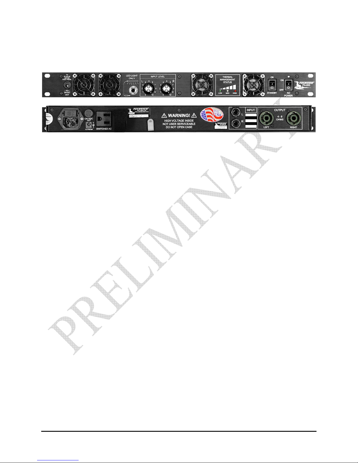
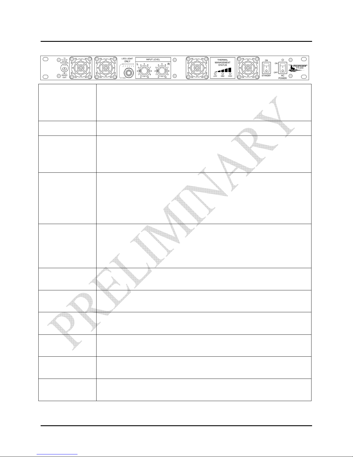
PA-4200 STEREO POWER AMP CONTROL FUNCTIONS, JACKS, & INDICATORS:
FRONT PANEL
AC Power Switch This is the main power switch for the system. This switch also controls the AC
receptacle on the rear panel, the 24 VDC output for the Telonics preamps (rear
panel), and the 24 VDC output for FP-100 Foot Pedal (front panel). Eliminates
the need for a power strip in 3U rack systems.
Blue LED The blue LED will indicate that the main power is turned on.
Standby Switch This switch allows control of the AC power to the power amp alone, independent
of the system power. When placed in the Standby mode it allows for quicker cool
down of the amplifier if needed. This switch must be on in normal use as it
effectively “mutes” the power amplifier section in the off position.
Thermal
Management Status
Green LED The green LED will blink; on for a short time then off, once a second while the
Yellow LED The yellow LED will come on solid if the temperature is at or above the medium
Red LED The red LED will come on solid if the temperature is at or above the high set
R Input Level This is an input attenuator for the right audio channel. Fully clockwise will allow
L Input Level This is an input attenuator for the left audio channel. Fully clockwise will allow
LED Light Only This 1/4” jack powers up the optional LED light bar. CAUTION: NO AUDIO
24VDC Output This jack provides an isolated 24 volts DC to power up the MVP600 foot pedal.
The Thermal Management Status indicates the temperature status of the power
amplifier. The LEDs indicate a low (green), medium (yellow), or high (red)
temperature range.
The LEDs will also indicate a fan speed out of specification condition as
described later, in the Thermal Management System; Fan Speed out of Spec
Indication paragraph.
temperature is below the Low setting. This “wink” (short blink, once per second)
lets you know that the Thermal Management System is working. As the
temperature increases the green LED will come on solid while the temperature is
at or above the low setting.
set point.
point.
maximum output from the amplifier.
maximum output from the amplifier.
CABLES SHOULD BE PLUGGED INTO THIS JACK.
This jack accepts a special twist lock plug for a secure connection of power to the
pedal.
Telonics PA-4200 Power Ampl if ier 3
Page 4

PRELIMINARY
PA-4200 STEREO POWER AMP CONTROL FUNCTIONS, JACKS, & INDICAT ORS:
REAR PANEL
AC Power Input 110-120VAC input*. Standard IEC 60320 C13 receptacle on 18 AWG
cord is recommended. The inlet is fused with an 8 amp 250VAC
5x20mm ceramic Slow Blow fuse.
24VDC Out 24 volt DC to power the Telonics preamplifier.
AC Power Outlet Switched 110-120VAC outlet, fused with 2 amp 250VAC 5x20mm glass
Input L, R Dual ¼” mono tip sleeve (TS) jack for right and left input signals.
Output Left, Right Speakon combo jack for output to a minimum 4 ohms speaker load. Also
*NOTE: Standard versions are wired for domestic use only. Export units are available on special
order. Export AC Power Input range is 170-230 VAC, 50-60 Hz. CAUTION: Voltages outside
this range could damage the unit and cause a shock hazard.
Slow Blow fuse. Note: This outlet is not available in the export version.
accepts ¼” TS plug.
Standard IEC 60320 C13
receptacle is required for the
Power Amp side.
UK Plug BS1363A
(Supplied with 13A fuse).
Telonics # WI-008667-001
Telonics PA-4200 Power Ampl if ier 4
Europe IEC 884/CEE7-VII
Telonics # WI-008669-001
Australia Plug AS 3112
Telonics # WI-008668-001
Page 5

PRELIMINARY
PA-4200 THERMAL MANAGEMENT SYSTEM
INTRODUCTION
The cooling system for the PA-4200 Audio Amplifier consists of four variable-speed fans and an
intelligent digital controller circuit. The speed of the fans is determined by the temperature at
multiple key points within the amplifier. The controller is designed to run the fans at the slowest
possible speed sufficient to maintain the amplifier at a safe operating temperature, and thus yield
the quietest possible operation. As the temperature of the amplifier increases, the fan speed is
increased as necessary.
TEMPERATURE INDICATION
The amplifier’s temperature is indicated on the front panel via the status LED’s:
Blue = Thermal Management System power is on
Green = Temperature is above the Low temperature threshold
Yellow = Temperature is above the Medium temperature threshold
Red = Temperature is above the High temperature threshold
The following table shows the state of the Green, Yellow and Red LED’s, and the fan speed for
the specified temperature ranges:
Temperature LED Status Fans
>= < Green Yellow Red No.
Low Wink off off 2 Minimum
Low Medium ON off off 4 Increasing
Medium High ON ON off 4 Increasing
High ON ON ON 4 Maximum
Speed
Notes:
‘Wink’ = short blink, once per
sec.
‘ON’ = on solid.
FAN SPEED OUT OF SPEC INDICATION
The speed of the fans is measured in order to make sure that the fans are operating properly and
to assure adequate cooling for the amplifier. If the speed of any of the fans is out of allowed
tolerance for five or more consecutive seconds, then the LEDs defined by the above table (i.e.,
Green and Yellow for temperature between Medium and High) will blink long flashes twice per
second; they will be on for ¼ second, and off for ¼ second. This is a flash that is easily
discernible from the ‘Wink’ condition described above. If the speed of all of the fans returns
back to within tolerance, the blinking will stop, and the LEDs will return to the state described in
the table above. Should this ‘Flashing’ persist, this could be indicative of a fan failure, and could
lead to the amplifier overheating. In this case, the amplifier should be returned to the factory for
repairs.
Telonics PA-4200 Power Ampl if ier 5
Page 6

PRELIMINARY
PA-4200 THERMAL MANAGEMENT SYSTEM CONTINUED
FAN-WEAR BALANCING
In order to further minimize the noise produced by the fans, and to prolong the life of the fans,
the four fans are divided into two pairs. Whenever the temperature of the amplifier is below the
Low temperature threshold, one of the pairs is turned off, and one pair continues to run at the
minimum speed. In most environments, when the amplifier is idle or played at lower levels, a
single set of fans is adequate to maintain a desirable temperature within the amplifier. Whenever
the amplifier temperature rises above the Low threshold, the second pair of fans is turned on
slowly in addition to the first pair; therefore, all four fans will be running, initially at the
minimum speed. Should the temperature of the amplifier continue to rise, the speed of all four
fans will be slowly increased accordingly; if the temperature of the amplifier drops, the speed of
all four fans is slowly reduced accordingly. If the temperature of the amplifier again drops
below the Low threshold, then the second pair of fans is turned back off. The pair of fans which
will ‘always be on’ will be alternated every time that the power is cycled. Thus, in the long run,
the wear on the fans will be balanced.
Telonics PA-4200 Power Ampl if ier 6
Page 7

PRELIMINARY
PA-4200 MECHANICAL DATA
Chassis Material Aluminum
Finish Hard Anodized
Front & Rear Panel Markings Laser Etched
Panel
Meets industry standard specifications (EIA-310-D,
CEA-310-E, IEC 60297-3-100, and DIN 41494-7).
Panel Thickness 0.13 in. (0.33 cm)
Panel Height 1.70 in.(4.32 cm) typical
1.75 in. (4.45 cm) max
Panel Width 19.0 in. (48.3 cm) max
Internal chassis/cabinet width
17.32 in. (44 cm)
(including screws)
Internal chassis/cabinet height 1.73 in (4.39 cm) typical
1.75 in. (4.45 cm) max
Internal chassis/cabinet depth 7.63 in. (19.4 cm)
Total protrusion of jacks beyond
0.425 in. (1.08 cm)
rear chassis apron (max)
Total protrusion of knobs beyond
front panel
Total weight 5.20 lb. (2.358 kg)
Telonics PA-4200 Power Ampl if ier 7
0.725 in. (1.842 cm) max
 Loading...