

Telonics TCA-500C 15-1U, TCA-500C 12-MINI, TCA-500C 15-MINI, TCA-500C 12-1U, TCA-500C-1U User Manual
...Page 1
Telonics TCA-500C Combos, Mini-
15-1U COMBO
12-1U COMBO
12-
MINI
COMBO
SPEAKER
ENCLOSURE
HEAD
UNIT
SUPER
TWIN
COMBO
SPEAKER
ENCLOSURE
Combos, Head Unit, Preamplifier
and External Speakers
User Manual
TCA-500C
TCA-500C
TCA-500C-1U
TCA-500C
TCA-500C
MINI-15 EXTERNAL
MINI-12 EXTERNAL
TLF-PRE500
LITE-FLIGHT
PREAMPLIFER
SYSTEM
TCA-500C 212
©2017 Telonics, Inc. All Rights Reserved
PB-009289 Rev E. 2018.02.16
Page 2
I
MPORTANT SAFETY INFORMATION
CAUTION: Risks of electrical shock – DO NOT OPEN
CAUTION: To reduce the risk of electric shock, do not remove from cabinet. No user
serviceable parts inside. Refer Servicing to Telonics service personnel.
WARNING To prevent electrical shock or fire hazard, do not expose this appliance to rain or
moisture. Before using appliance, read the operating guide for further warnings.
WARNING:
** HIGH SOUND LEVELS CAN IRRIVERSEABLY DAMAGE YOUR HEARING **
A single brief exposure to a high noise level can permanently damage your hearing. Hearing
damage can also occur gradually at much lower noise levels, if there is enough exposure over
time. Evidence suggests the risk of damage to hearing occurs when the level exceeds 85dB.
An example of 80dB might be an alarm clock and 90dB a lawn mower. Current evidence
suggests ears can tolerate up to 2 hours of exposure at 91dB, but damage can occur with only 1
minute of exposure at 112dB. Levels of 110dB on a bandstand are frequently recorded.
Whenever you use this apparatus carefully evaluate the sound level. In a band situation
PROTECT YOUR HEARING.
Note excessive headphone and in-ear monitor levels can also
ALWAYS
damage hearing. Carefully evaluate and minimize the level when using the headphone output.
Do not operate near heat sources, such as radiators.
Protect cords from being walked on or pinched.
Do not use the apparatus with a damaged or frayed lead.
Unplug this apparatus during lightning storms.
Unplug this apparatus when unused for long periods of time.
No naked flame sources should be placed on the apparatus.
Telonics TCA-500C Combo Amp
PB-009289 Rev E
2
Page 3

T
ABLE OF CONTENTS
Important Safety Information .................................................................. 2
Table of Contents ...................................................................................... 3
Electromagnetic Compatibility & Warranty ........................................... 4
Introduction .............................................................................................. 5
Front Panel ............................................................................................... 7
Rear Panel ............................................................................................... 22
TCA-500C 15” Mini-Combo (Internal Speaker) Amp Control
Functions ................................................................................................ 32
TCA-500C 12” Mini-Combos (With External Speaker) Amp Control
Functions ................................................................................................ 33
TCA-500C Head Unit (only) Amp CONTROLS Functions &Jacks ... 34
TCA-500C Combo Amp Setup Settings: ................................................ 35
TCA-500C Thermal Management System ............................................ 37
Frequently Asked Questions .................................................................. 39
(Optional) External Control Units ....................................................... 41
Handy Patch MIDI Controller MC100 ................................................. 43
Using Small “Stomp Box” Effects Units with the TCA-500 series
Amplifiers ................................................................................................ 46
How To Be A Tone Master – Subtractive Equalization ....................... 48
Telonics Tilt-Back Foot .......................................................................... 50
Mechanical Data .................................................................................... 51
Electrical Data ........................................................................................ 52
Mechanical Outline Drawings ............................................................... 53
Telonics TCA-500C Combo Amp
PB-009289 Rev E
3
Page 4

Electromagnetic Compatibility & Warranty
EMC/EMI
This equipment has been assessed for radiated and conducted emissions compliance with
reference to FCC Part 15 Class B and EN61000-6-3 standards and found to comply with the
limits.
This device complies with Part 15 of the FCC Rules. Operation is subject to the following two
conditions:
(1) This device may not cause harmful interference, and
(2) This device must accept any interference received, including interference that may cause
undesired operation.
This device complies with Canadian Interference regulations CAN ICES-3(B)/NMB-3(B).
Note: These limits are designed to provide reasonable protection against harmful interference in
a residential environment. This equipment generates, uses, and can radiate radio frequency
energy and, if not installed and used in accordance with the instructions, may cause harmful
interference to radio communications. However, there is no guarantee that interference will not
occur in a particular installation. If this equipment does cause harmful interference to radio or
television reception, which can be determined by turning the equipment (including the PSU), off
and on, the user is encouraged to try correcting the interference by one or more of the following
measures:
• Reorient or relocate the receiving antenna.
• Increase the separation between equipment and the receiver.
• Connect the equipment PSU to an outlet on a circuit different from the one to which the
receiver is connected.
• Consult the dealer or an experienced radio/TV technician for help.
CAUTION: All warranties and certifications are null and void if this equipment is opened
and tampered with in any way.
Warranty
We warrant this product to be free of defects in materials or workmanship for a period of one
year after delivery to the original purchaser. Our obligation under this warranty is limited to the
replacement or repair of any part or parts which prove upon our examination to be defective.
This warranty does not apply to damage resulting from transportation, misuse, abuse, or
alteration.
Telonics TCA-500C Combo Amp
PB-009289 Rev E
4
Page 5
I
NTRODUCTION OF THE TELONICS
F
RONT PANEL (COLOR LABEL OPTION SHOWN
R
EAR PANEL
TCA-500C
)
Congratulations on purchasing one of the world’s finest professional instrument combo
amplifiers! The TCA-500C combo amplifier is a state of the art audiophile quality unit designed
and built with the latest and best sounding technologies. It has been carefully engineered to
provide every function and convenience possible within its cost/benefit ratio, for the professional
musician. There is a reason for every function provided. The user is encouraged to read this
manual in order to achieve the highest level of performance provided by these capabilities.
The TCA-500C combo amplifier gives you dramatically better control of your sound. The result
is transparent smooth clean sound, tight bottom end and silky highs. It is designed to
accommodate many different instruments and as such, its controls cover a wider range of options
than previously offered to the professional musician. Accordingly, for any given instrument, the
controls may ‘feel’ more sensitive when adjusted for a specific instrument. For this reason, the
user is encouraged to make smaller adjustments while listening carefully. Final adjustments
should always be made with the ear, without regard to where one “expects” the knob to be.
Telonics TCA-500C Combo Amp Features:
• Superb string separation at all volume levels. No muddiness!
• All pure analog, main signal chain. No digitization of your sound thru A/D or D/A
converters.
• Pre EQ Insert for EQ or 3-wire Pot Pedal hook-up.
• Warm tube-like, even-order harmonic sound with crystal clear highs.
• Ultra low noise – studio quality.
• Exceptionally high headroom.
• High output level available on demand.
• 500 Watt Power Amp section.
• Studio Pre-EQ parallel effects loop with adjustable SEND and RETURN levels to
accommodate any EFX unit(s) (rear panel mounted).
• Built in reverb with front panel level control and remote control jack.
Telonics TCA-500C Combo Amp
PB-009289 Rev E
5
Page 6

T
ELONICS
• Overload LED indicator.
• Master Wet/Dry fader control – controls internal effects and parallel EFX loop.
• Built-in “TBro” effect with remote control jack.
• Pedal Switch jack on rear panel allows switching “TBro” and Reverb remotely.
• Special “Blend” EQ control for personalizing your tone or adjusting for venue. (Once
properly adjusted, Master volume and Blend are generally the only adjustments used).
• Auxiliary AC power outlet, switched with main power switch.
• Special Power On/Off circuit to minimize “pops” and speaker damage.
• Built in high output headphone amp with separate volume control.
• Super quiet Mute circuit with LED indicator.
• Digital Thermal Management System.
• 24 volt DC jack on front panel to power Telonics 24 VDC FP-100 foot pedal.
TCA-500C C
(C
ONTINUED
OMBO AMP FEATURES:
)
• 24 VDC or 9 VDC auxiliary power socket option on rear panel to power external effects
units (9 VDC on Mini-Combo Models).
• Balanced XLR Direct output for stage and studio use. Includes ground lift switch.
• Analog modeling for Direct Out for live venue or studio use, with preset modeling.
• Buffered tuner output (front panel) - active full-time, even when mute is ON.
• Auxiliary stereo input (on rear panel) for home practice or solo gigs with front panel level
control. For CD/mp3 players or for use as a second effects RETURN. Also routed to DI
for recording.
• Rear Mounted Power Amplifier On/Off switch for preamp-only use in Studio.
• Highest Quality Telonics NEO Speaker (12 or 15 inch).
• 1U rack space provided which may be used for EFX Units, tuners, etc.
• Built-in cabinet-wide LED lighting for low light venues with back panel switch to control
On/Off and brightness level.
• Telonics designed Tilt-Back Foot for ease of viewing and access to controls
• Highly abrasion-resistant outer surface, durable Baltic Birch plywood construction
throughout. Made for years of trouble free use.
• International versions available for export that comply with CE and RoHS directives.
• Proudly made in the U.S.A. by musicians and engineers.
Telonics TCA-500C Combo Amp
PB-009289 Rev E
6
Page 7
TCA-500C C
OMBO AMP CONTROL FUNCTIONS, JACKS, & INDICATORS
F
RONT PANEL
:
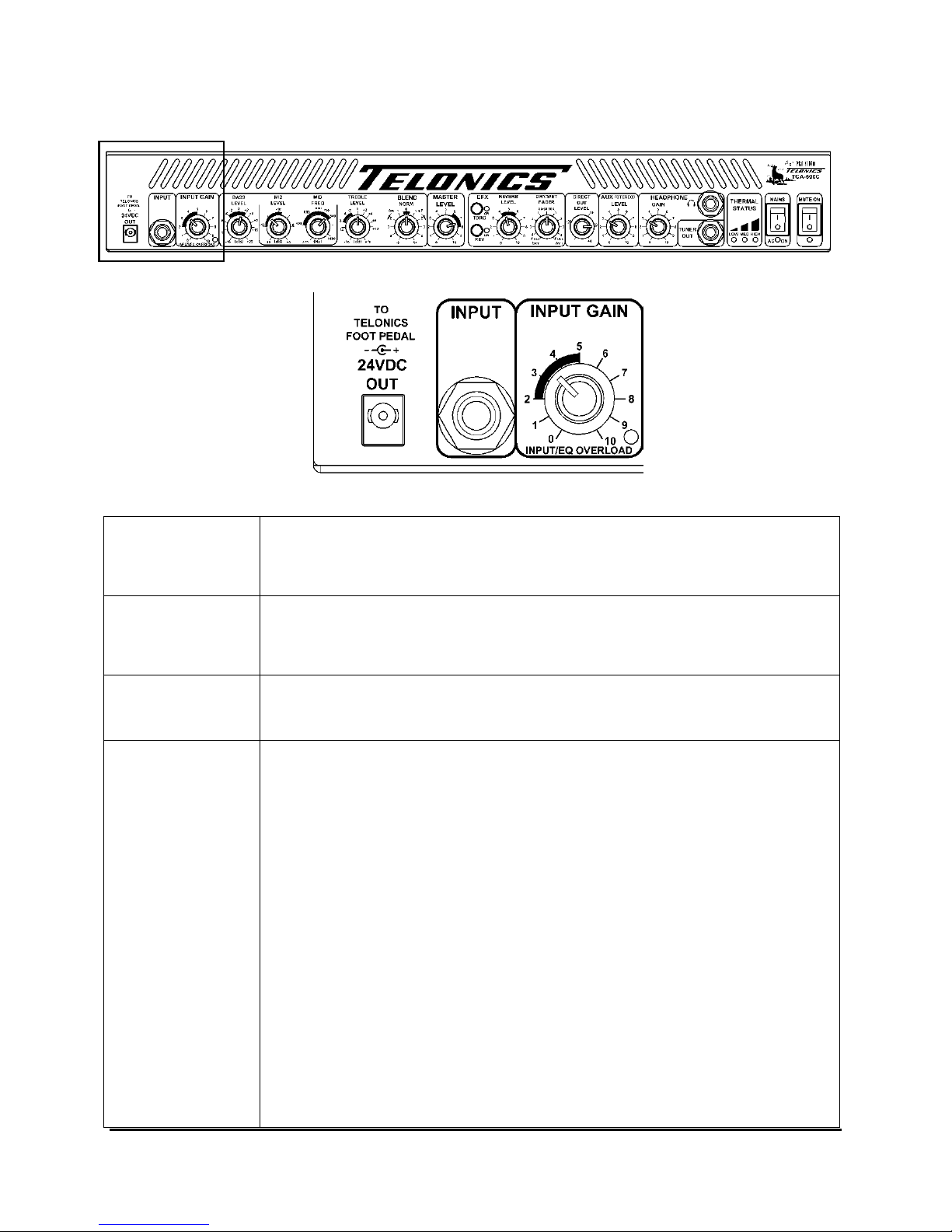
24VDC Output
Input
NOTE:
Input Gain
and
Red Overload
LED
This socket provides an isolated 24 volts DC to power up the FP-100 foot pedal.
It accepts a special twist lock plug for a secure connection of power to the pedal.
A power lead with locking connectors is supplied with the TCA-500C Amplifier.
High impedance (1Meg Ohm) instrument input - will not load down your guitar
pickup or adversely affect your tone. It accepts a standard 1/4 inch type TS (Tip
and Sleeve) Mono plug for guitar level signals.
Prior to adjusting the following controls it is best to start out with the
EQ controls flat. Check to see that the Bass, Mid Level, Treble, Blend,
and Dry/Wet controls are at zero (0).
This control sets the gain for the first amplification stage. And is used in
conjunction with the MASTER LEVEL control, it also affects the level for
the Insert (Pre EQ) “Send” jack and the maximum level to the EFX Send
jack (both of which are on the rear panel). Start at 3 or 4 and adjust as
needed.
It’s important to understand the function of this control as its setting
impacts other controls and the overall sound. When a guitar signal is fed
into the amplifier, it is necessary to increase the signal level to minimise
noise that might be added in the following stages. Typically, guitar pickups
with a high output require a lower gain setting and pickups with a low
output required a higher gain setting.
In the lower right-hand corner of the Input Gain box is a red (Input/EQ
Overload) LED that indicates when an overload is occurring in the preamplifier stage. If this LED flashes on frequently, or stays on while the
guitar is played, the Input Gain setting is too high and should be reduced
in order to avoid distortion of your sound.
Telonics TCA-500C Combo Amp
PB-009289 Rev E
7
Page 8

TCA-500C C
Input Gain
and
Red Overload
LED
(continued)
NOTE: For the best EQ result, make sure the Blend control is at zero (0) while adjusting
the Bass, Mid, and Treble tone controls.
OMBO AMP CONTROL FUNCTIONS, JACKS, & INDICATORS
F
RONT PANEL (CONTINUED
)
The following text describes how the Input Gain should be set with a
typical arrangement:
i) We assume that in most cases, the output of your guitar connects to
your volume pedal input and the output of your volume pedal connects
to your amplifier (Note; always use good quality leads for these
connections and try to ensure they’re no longer than they need to be to
reach the jacks. Make sure they are not a trip hazard).
ii) With the Master Level control set to 1, your volume pedal set to
maximum and Input Gain control set to 1, play some nice big chord
groups slightly harder than you would normally play; slowly increase
the Input Gain control until the Overload LED just starts to occasionally
flash, then reduce the Input Gain control until it ‘just’ ceases to flash as
you strike the chords.
iii) You have now set the optimum level for the Input Gain control. You
should not need to adjust the Input Gain control unless you change
your guitar or volume pedal. We suggest you note this setting.
A common mistake is to see players using the Input Gain to control
output volume. The problem with this is the Input Gain control
affects the level sent to the effects unit, so once adjusted as outlined
above, it need not be moved. Use the Master Level control to adjust
the amplifier volume as needed.
Always use the Master Level to control output volume after the
Input Gain control has been adjusted as outlined above.
:
Telonics TCA-500C Combo Amp
PB-009289 Rev E
8
Page 9
TCA-500C C
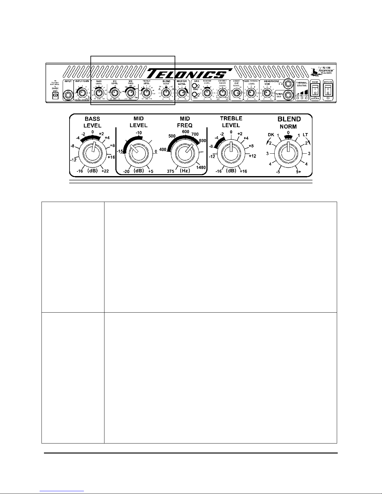
Bass Level
Mid Level
OMBO AMP CONTROL FUNCTIONS, JACKS, & INDICATORS
F
RONT PANEL (CONTINUED
)
:
(Note: See pages 33 and 34 for common settings.)
Controls low frequency response. Turning clockwise will boost the bass up to
+22dB. Turning counterclockwise will decrease the level down to -16dB.
Start at 0 (flat) and adjust to taste.
Note that it is a common error to boost the bass excessively, as this dulls the
character of the strings. Remember that it is always best to use “Subtractive
Equalization” as discussed later in this manual. i.e., instead of boosting the Bass,
reduce the Mids and/or Treble. A simple check for excessive bass boost is to
listen closely as you strike a lower string repeatedly. Start with the Bass Level
control set at -4 or -5. While listening to the character of the string, advance the
Bass Level control slowly clockwise. At some point (usually around +1 to +3, the
character of the sound will change and will sound like more of a “thud” and have
a muted quality. For most people, that is too much bass boost, so back off the
control counterclockwise slightly until the sound is once again clear and clean.
It is necessary that the user understand that the Mid Level and Mid Frequency
controls work ‘together’.
mid-range frequency shaping; they are perhaps the most important tone
shaping controls and they ‘must’ be set properly to achieve a balanced
sound. These controls allow the player to compensate for the ear’s normal
increase in sensitivity to mid-range frequencies and the guitar’s resonance
around those frequencies.
The Mid Level control determines the amount of effect which the Mid Frequency
control has on your sound.
It sets a boost or cut in the mid-range frequencies, which are selected by the Mid
Frequency control. Mid Level is adjustable from -20dB cut to +5dB boost.
If you were to set the Mid Level control to Zero dB (3 o’clock knob position), the
Mid Frequency control would ‘do nothing whatsoever” to your sound, it would
have NO effect on your tone.
These two controls are used together to set up the
Telonics TCA-500C Combo Amp
PB-009289 Rev E
9
Page 10

TCA-500C C
Mid Level
(continued)
Mid Frequency
OMBO AMP CONTROL FUNCTIONS, JACKS, & INDICATORS
F
RONT PANEL (CONTINUED
Since the mid-range frequencies are tiring to the human ear, it is almost always
necessary to CUT or reduce them. The Mid Frequency control allows the user to
choose the center frequency at which the mid frequencies are reduced, to suit his
or her ear.
)
:
The following text describes how the Mid Level and Mid Freq
controls should be set for steel guitar:
i) We assume the Input Gain control has already been set. Set the Bass
Level control to 0, the Treble Level control to 0, the Blend control to 0
and the Master Level control to 2. All effects should be OFF.
ii) Now set the Mid Level control fully clockwise (+5) and set the Mid Freq
midway (600 Hz). Note when you pick a string the Overload LED may
flash; don’t adjust the Input Gain control. Note that the overload
monitoring circuitry monitors both the output of the gain section and
the EQ section; because we’ve set the Mid Level control to full boost it
causes the overload.
iii) Ensure the combo speaker is pointed towards your ear. Pick one or two
strings in the center string grips and slide the bar over the normal
range of the fret board you would use. As you are doing this, tweak the
Mid Freq control up and down around the 400 to 800 region; it’s handy
to have a friend rotate the Mid Freq control as you play. At one point
over the region you might possibly notice, no matter where you are on
the fretboard, a ‘honky’ midrange sound is heard that’s a little
unpleasant on the ear. It does take practice and time to learn how to
detect this point, so don’t be concerned if it’s not clear the first time
you attempt this. Note the Overload LED may help detect this point,
quite often it flashes more as you hit area’s where’s there’s more
resonance.
Once you have found the honky, excessive ‘middle’ sounding frequency,
rotate the Mid Level control to around the 10 o’clock position (-12dB). As
you play your guitar tweak the Mid Level control up and down around this
point until it sounds balanced in the mid-range. Generally, the most
suitable setting is between -15 dB and -12 dB for most people. Don’t
worry about setting the bass and treble controls until you’re happy that the
mid-range is the best it can be.
Always, Always, make the above adjustments with the Bass and
Treble controls at zero.
Sets the frequency at which the Mid Level control has an effect. Several
frequency intervals between 375 Hz and 1400 Hz are marked. Its effect is
determined by the setting of the Mid Level control. Proper adjustment is achieved
as outlined above.
Telonics TCA-500C Combo Amp
PB-009289 Rev E
10
Page 11

TCA-500C C
Treble Level
OMBO AMP CONTROL FUNCTIONS, JACKS, & INDICATORS
F
RONT PANEL (CONTINUED
Adjusts the high frequency level of the sound generated by your instrument. Start
at 0 (flat) and adjust to taste. Turning clockwise boosts the level of highs up to
+16dB, turning counterclockwise cuts the level of highs down to -16dB.
)
Note: We always recommend using the minimum amount of Bass
and Treble tone shaping to achieve the sound you desire. These
controls are very powerful; they can greatly cut or boost the gain of
the lower and higher frequencies. If an extreme setting of this control
is required to achieve a balanced sound you may have an issue with
your Mid Level and Mid Frequency control settings, or with your
guitar pickup, leads & volume pedal.
After setting the Bass Level, Mid Level, Mid Freq and Treble Level
controls we suggest you note the settings.
Blend As indicated earlier this control should be at zero (0) while setting the EQ.
Only set this control after you have set all the other tone controls.
This is to be used as a sonic “shading” control and, like any seasoning, a little
goes a long way. Start at 12 o’clock. Clockwise yields a “Mooney” bright
aggressive sound; counterclockwise gives you a mellow, darker tone.
The Blend control is initially one of the most confusing settings to
understand… until you start using it. After using the combo for a few
gigs you may find it’s the only tone control you need! Once the bass,
mid and treble controls have been set the amplifier might be
considered as calibrated to your style and guitar sound.
As you rotate the Blend control clockwise you’ll notice the treble
increases and the bass decreases.
As you rotate the Blend control counterclockwise you’ll notice the
treble decreases and the bass increases.
This control is like a ‘one stop shop’ compensating for the affect the room
acoustics has on the overall sound. It’s quite remarkable how a small
tweak of this control can sweeten up your sound in a live performance
situation. And being a single control it’s easy to remember where you
started before you started tweaking.
Normally, players leave this control at zero and only adjust it slightly
between +1 and -1 to compensate for the venue (room size, crowd size,
bandstand configuration (even for relative humidity changes, as sound
propagates differently with humidity changes).
NOTE: See the TCA-500C Combo Amp Setup Settings section for starting values for
different types of settings.
:
Telonics TCA-500C Combo Amp
PB-009289 Rev E
11
Page 12
TCA-500C C
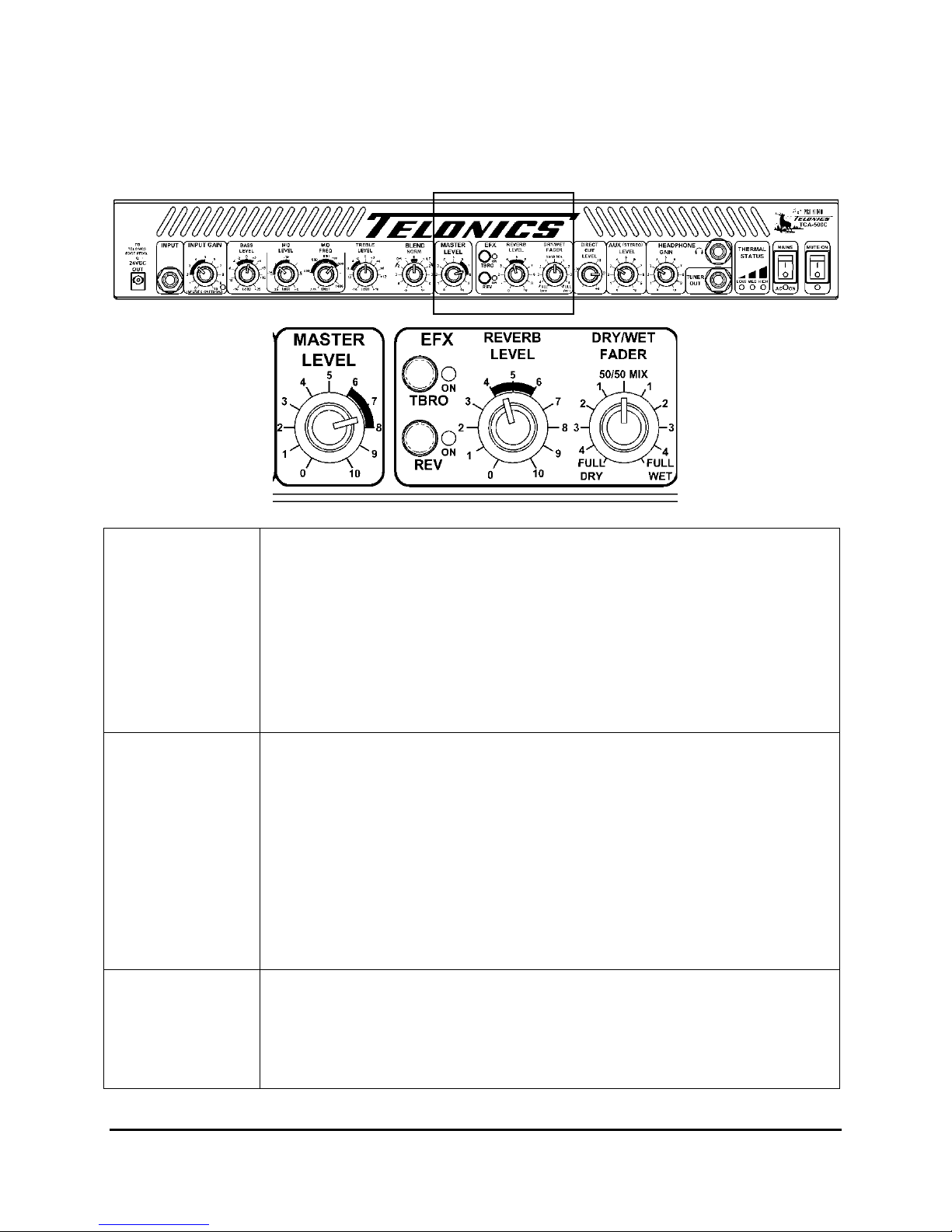
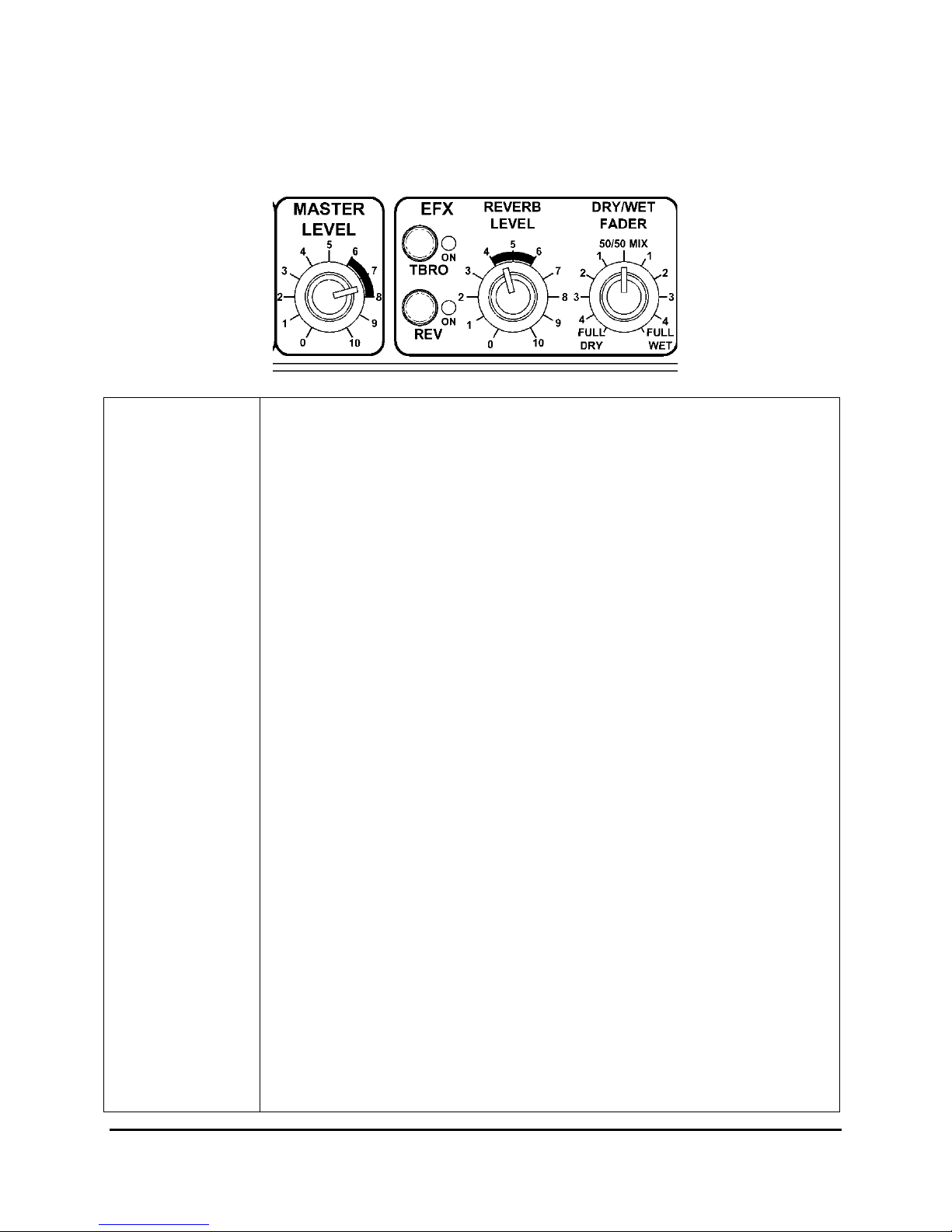
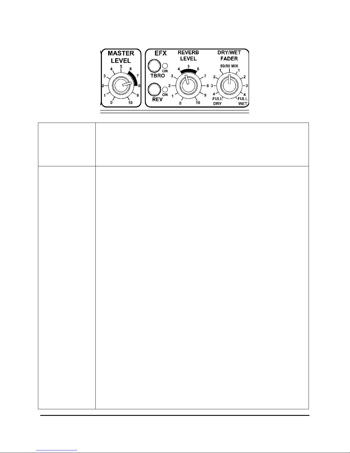
Master Level
TBRO
Reverb Level –
Rev ON button
OMBO AMP CONTROL FUNCTIONS, JACKS, & INDICATORS
F
RONT PANEL (CONTINUED
)
Sets the overall output level of the Combo Amp. Adjust this after you have set
the Input Gain and EQ. This is your main volume control knob – to be adjusted as
necessary as you play a gig. For normal size venues, the customary range is
between 6 and 8 or less.
The Master Level control sets the overall signal level sent to the power
amplifier (PA). Adjustment of this control will not affect the Direct Out
level. This allows players to adjust their own stage level without
affecting the signal level sent to the mixing desk – a handy feature!
This push button switch will activate a “TBro” type effect. The green “TBro”
‘ON’LED will light when TBro is active. The Foot Switch connector on the rear
panel can be used to turn the TBro function Off and On if the TBRO pushbutton
switch on the front panel is pushed On (in). If either this switch or an external
switch is in the Off position, the effect will remain Off. (When an
external/remote switch is not used, the default is On. (See back panel Foot
Switch)
An optional remote switch box for steel guitar (and a remote foot switch for other
instruments) is available for rapid remote control of the TBro and Reverb
functions. The usage of these optional accessories is outlined later in this manual.
The Reverb Level control determines how much of the internal reverb signal is
applied to the Wet/Dry Fader control. The input level to the reverb circuit is
affected by the Input Gain control level (as mentioned earlier). The reverb input
is a combination of the dry input after the EQ controls and the Post EQ EFX
Return signal (rear panel).
:
Telonics TCA-500C Combo Amp
PB-009289 Rev E
12
Page 13
TCA-500C C
Reverb Level –
Rev ON button
(continued)
OMBO AMP CONTROL FUNCTIONS, JACKS, & INDICATORS
F
RONT PANEL (CONTINUED
)
:
The Rev push button switch will activate the internal reverb circuit. The green
LED will light when the reverb is active. The Foot Switch connector on the rear
panel can be used to turn the internal reverb Off and On if the Rev pushbutton
switch on the front panel is pushed On (in). If either this switch, or an external
switch, is in the Off position, the reverb will remain Off. When an external
remote switch is not used, the default is On. (See back panel Foot Switch)
The built-in reverb is useful if you don’t have an effect processor installed.
It can be switched On/Off from the front panel using the Rev ON button or
by remote control using the Footswitch jack on the rear panel. The reverb
sound has been preset to a general ambience algorithm; the Reverb Level
control adjusts the amount of reverb introduced.
The built-in reverb signal is added to the signal returning from the
EFX Return jack that feeds the Wet side of the DRY/WET Fader.
This means, the DRY/WET Fader must have a proportion of Wet
signal set or the built-in reverb will not be heard. I.e. if the
DRY/WET Fader is set fully Dry no reverb will be heard.
If the TCA-500C is used with a 19” rack effects processor, (such as a
Lexicon MX-200, a T.C. Electronics G-Major/II, or other 1U space multieffects unit), we would recommend the built-in reverb be turned off and
patches set up on the effects processor; the reverb algorithms of a good
quality effects processor should be superior to the built-in reverb.
1U 19” Rack Space – (Note: The 1U Rack Space is not available
on the Mini-Combo units.) The TCA-500C has a built in rack space
below the main amplifier chassis. If no effects processor is installed
in this space a blanking plate should be installed. On the rear panel a
mains switched outlet is provided to power up the effects processor;
50W max. Although the general thought behind providing this space
is to enhance the reverb and delay effects, almost any 1U unit no
more than 8 inches or 200mm deep could be installed in this space.
Telonics TCA-500C Combo Amp
PB-009289 Rev E
13
Page 14

Telonics TCA-500C Combo Amp
PB-009289 Rev E
14
Page 15
TCA-500C C
Reverb Level –
Rev ON button
(continued)
DRY/WET Fader
OMBO AMP CONTROL FUNCTIONS, JACKS, & INDICATORS
F
RONT PANEL (CONTINUED
)
:
An optional remote switch box for steel guitar (and a remote foot switch for other
instruments) is available for rapid remote control of the TBro and Reverb
functions. The usage of these optional accessories is outlined later in this manual.
A TRS (Tip-Ring-Sleeve, 3- conductor) Stereo cable is necessary to connect most
multi-effect units to an external control box or foot pedal.
This fader controls the ratio of “dry” (without effects) and “wet” (with effects)
signals sent to the Master Level control. Counterclockwise is dry, clockwise is
wet.
DRY/WET FADER – EFX SEND + LEVEL (rear panel) - EFX
RETURN + LEVEL (rear panel) – The Dry/Wet Fader and rear panel
effects loop is a very powerful feature that allows effects to be added to
the analog signal chain in a number of ways.
The level sent out to the effects unit can be adjusted using the EFX Send
Level on the rear panel. This is adjustable to drive effect inputs from,
-30dB to +4dB; the +4dB setting generates the highest output. It’s very
important to ensure the TCA-500C Overload LED just starts to blink
BEFORE the effects processor input level reaches its maximum input
level or clipping point. The average user can easily ensure the correct
and proper EFX send level by looking up the preferred level in the
manual for the appropriate multi-effects units and setting the EFX
RETURN and EFX SEND controls on the TCA-500C to specified
levels.
Normally these levels will be -10 dBu, -8 dBu, -4 dBu, 0 dBu or +4
dBu. The TCA-500C provides the ability to match virtually any high
quality EFX units.
The level returned from the effects unit can be reduced or boosted using
the EFX Return Level on the rear panel. This is adjustable over the
range from, -30dB to +4dB; the +4dB setting applies the highest gain to
the returned signal. This level should be adjusted so the effects
processor output doesn’t cut or boost the signal; we call this ‘unity’
gain. A good way to check this is to set the effects processor to
‘bypass’: Then set the DRY/WET Fader fully Wet and then fully Dry,
you should notice virtually no change in volume; adjust the EFX Return
Level to achieve this.
Telonics TCA-500C Combo Amp
PB-009289 Rev E
15
Page 16

TCA-500C C
DRY/WET Fader
(continued)
OMBO AMP CONTROL FUNCTIONS, JACKS, & INDICATORS
F
RONT PANEL (CONTINUED
)
:
Your effects send and return levels should now be optimised. We
suggest you note the settings.
Series Effects Loop Mode
By setting the Dry/Wet Fader fully Wet, mono effects can be
introduced in a series chain i.e. the entire signal passes through the
effects loop and no thru signal is added to the effected signal. This
mode is useful where compression or modulation effects need to be
added.
Most effects processor manufacturers recommend series mode, there is
however a down side when using effects processors as part of series
chain. To generate high quality effects requires complex mathematics
and powerful processors, and time to perform the calculations. This
introduces a small delay as the signal passes through the effects
processor; this delay is called ‘latency’. A high performance processor
like the T.C. Electronics G-Major/2 introduces a delay of about 1.6
milliseconds into the signal chain.
If you consider reverb or delay effects this latency has negligible effect,
as the effect you are using is in fact delay based itself. But in a series
chain effect arrangement the straight through signal will also be delayed
by 1.6 milliseconds. There is considerable debate whether or not this
delay can be detected by the player. In tests we’ve carried out,
comparing series and parallel effects patches, it is our opinion that it is,
in fact, detectable by some players.
For this reason we would therefore not recommend using effects
processors in a series mode that introduce latency.
Telonics TCA-500C Combo Amp
PB-009289 Rev E
16
Page 17

TCA-500C C
DRY/WET Fader
(continued)
OMBO AMP CONTROL FUNCTIONS, JACKS, & INDICATORS
F
RONT PANEL (CONTINUED
)
:
Parallel Effects Loop Mode
By setting the Dry/Wet Fader at a mid-way point, the dry or thru signal
will be mixed with the effected signal. Typically a 12 o’clock position is
a good starting point.
The EFX Return Level should be adjusted so the effects processor adds
a typical effect level when the Dry/Wet Fader is in the 12 o’clock
position. Note the effects processor patch settings will also affect this
level; good noise / headroom practice must be considered when
developing patches.
In parallel mode the dry or thru signal is passed within the TCA-500C
and only the effected signal is returned by the effects processor. When
developing patches for parallel mode use, it is essential that the effects
processor is not allowed to pass an unaffected or straight through signal.
If this occurs, the true thru signal will mix with the latency delayed thru
signal and generate a modulated dry signal. This might in some
situations sound nice while setting up the patch, but in a live
performance or recording situation this often corrupts the general EQ,
messing up the natural sound of the instrument.
A well configured parallel effects loop, with a suitably configured delay
and reverb effect only being returned, enhances the natural sound of the
steel guitar and most other instruments. The T C Electronics G-Major/2
effects processor has some suitable routings with good control of both
the effect mix and effect level, for both delay and reverb. A number of
patches have been developed for this unit to be used with the
TCA-500C.
The ability to adjust the Dry/Wet Fader to control the effects level in a
live performance situation is another advantageous feature of parallel
mode.
Telonics TCA-500C Combo Amp
PB-009289 Rev E
17
Page 18
TCA-500C C
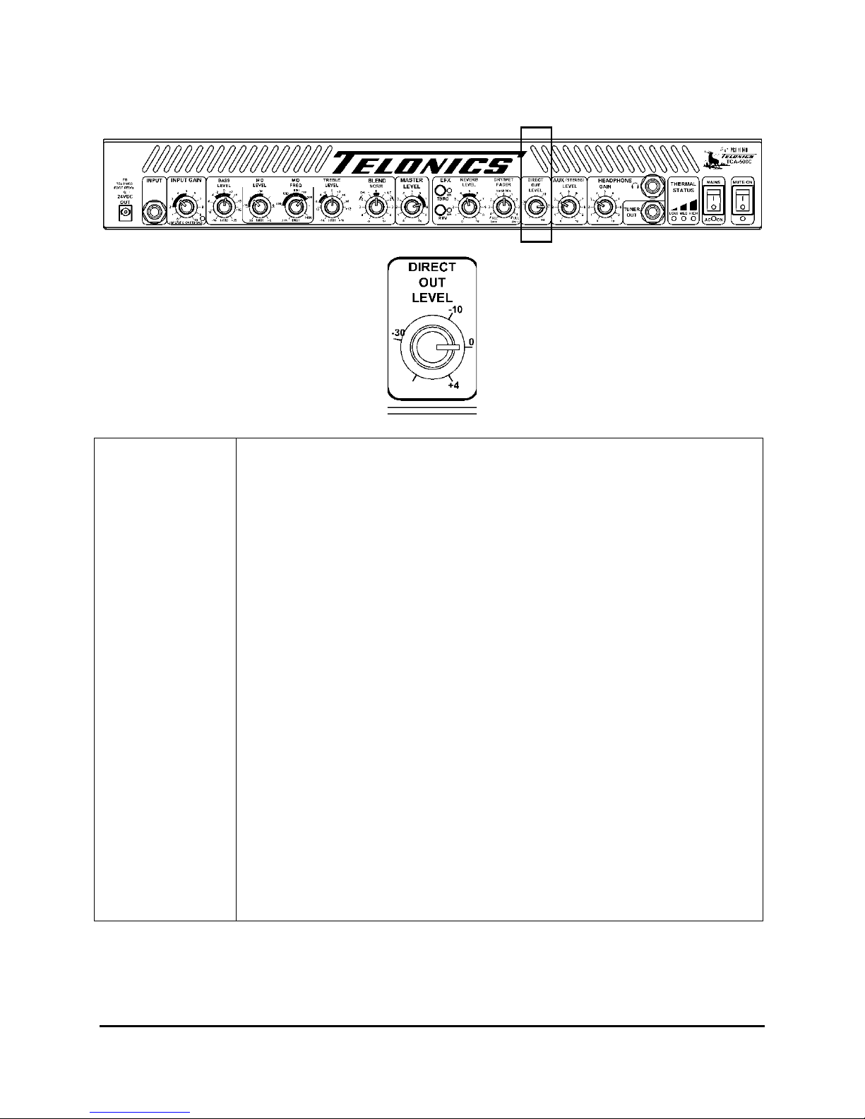
Direct Out
Level – Gnd Lift
OMBO AMP CONTROL FUNCTIONS, JACKS, & INDICATORS
F
RONT PANEL (CONTINUED
)
:
This level adjustment will allow you to match the D.O. signal you are sending, to
the proper level required by the mixer board or recording device. Most line level
devices are either +4dB or -10dB. You can adjust for either, however, you can
also adjust your Direct Output signal low enough for microphone inputs with
below -30dB adjustment- this is an unusual capability. This allows you to use
your high quality balanced XLR Direct Output with low end mixer boards which
only provide mic level inputs. (A very handy capability when you walk into a
new venue cold and have no idea what the sound person might have to work
with.)
The D.O. in the TCA-500C is analog modeled to deliver to a flat response
system, a very closely EQ’d approximation to what is output from the combo
speaker in its cabinet.
The signal sent from the XLR connection is balanced line and male
gendered (standard XLR out). The GND Lift push button (rear panel)
allows the combo earth to be separated from the DI earth to assist with
hum ground loop issues. The front panel Direct Level control allows the
signal sent to the desk/house board to be easily adjusted over a wide
range.
Note: when the Power Amp On/Off switch (rear panel) is Off (i.e. no
sound is output from the combo speaker, but the headphones output is
still active), the D.O. output remains ON because the preamplifier
section is ON.
Telonics TCA-500C Combo Amp
PB-009289 Rev E
18
Page 19
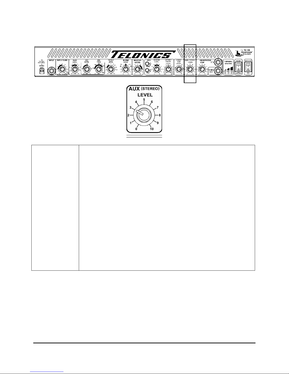
Aux Level
(Stereo)
TCA-500C C
The Auxiliary level control is used to set the level of background/track music
from MP3 players, CD players or other audio sources.
This input accepts a standard ¼ inch TS or TRS plug. Most MP3 players require a
1/8 inch TRS plug. Accordingly, a 1/8 inch-to-1/4 inch TRS cable is supplied
with the TCA-500C. Some CD players still utilize separate RCA jacks and
therefore require a dual RCA plug (male) to ¼ inch TRS plug cable. These are
readily available at most home entertainment electronics stores and are generally
stocked at Telonics as well.
As such, the Auxiliary Input is not designed for low-level instrument signals.
HOWEVER, it may also be used as a second channel input from an external
source such as a preamp and/or effects chain. For example, a musician who
doubles on a second instrument might connect the output of a preamp,
compressor and/or other EFX units following his instrument to the Aux input on
the rear panel of the TCA-500C, thus providing for quick switching to a Tele,
MandoCaster, mandolin, or other instrument.
Note: the Aux Input ties in after the EQ and Dry/Wet controls. You can only
control the level of this signal.
OMBO AMP CONTROL FUNCTIONS, JACKS, & INDICATORS
F
RONT PANEL (CONTINUED
)
:
Telonics TCA-500C Combo Amp
PB-009289 Rev E
19
Page 20

TCA-500C C
Headphone Gain
Headphone Jack
Tuner Out
Thermal
Management and
Power Amplifier
Off Status
OMBO AMP CONTROL FUNCTIONS, JACKS, & INDICATORS
F
RONT PANEL (CONTINUED
)
:
Adjusts headphone output level. Turn down when not in use.
The headphones output is a high level stereo ¼” TRS Jack output, capable
of driving headphones impedances of 8 Ohm or higher.
WARNING – High headphone levels may damage your hearing
The Headphones Gain control allows the headphone output level to be
adjusted.
The Mute ON and Power Amp switches do not affect the headphones
output.
This unit puts out up to half a watt per channel into 8 ohm – more than enough for
any player at home. We recommend using quality headphones such as Sony
model MDR 7505.
This is a buffered output so it will not load down the pickup or the rest of the
signal chain, nor will it allow noise from the tuner to get back into the system.
Output impedance is approximately 500 ohm. This output is buffered for feeding
to a guitar tuner.
The Mute ON switch does not affect this output; it is always ON.
The Thermal Management Status indicates the temperature status of the power
amplifier. The LEDs indicate a low (green), medium (yellow), or high (red)
temperature range. (For more details see the Thermal Management System
section)
These Three LED’s are also used to remind the user that the Power
Amplifier switch on the rear panel is in the OFF position when blinking in
groups of three (3) blinks, therefore no sound will be heard from the
speaker.
The LEDs will also indicate a fan speed out of specification condition as
described later, in the Thermal Management System; Fan Speed out of Spec
Indication paragraph.
Telonics TCA-500C Combo Amp
PB-009289 Rev E
20
Page 21

OFF
Main
s Power ON / OFF switch / AC ON LED (blue)
–
MUTE ON switch / LED (yellow)
–
TCA-500C C
OMBO AMP CONTROL FUNCTIONS, JACKS, & INDICATORS
F
RONT PANEL (CONTINUED
)
:
Green LED
Yellow LED
Red LED
When the Power Amplifier switch on the rear panel is switched to
blinking in groups of three (3) blinks, first showing the appropriate LED(s) to indicate temperature, then
all three LEDs will blink 3 times, then the LED(s) showing temperature will blink 3 times , then all
three, and so on. Note: If the temperature is High, then all three (3) LEDs will blink each time.
MAINS Switch /
Blue AC On LED
The green LED will blink; On for a short time then Off, once a second while the
temperature is below the Low setting. This “wink” (short blink, once per second)
lets you know that the Thermal Management System is working. As the
temperature increases the green LED will come On solid while the temperature is
at or above the low setting.
The yellow LED will come On solid if the temperature is at or above the medium
set point.
The red LED will come On solid if the temperature is at or above the high set
point.
these LED’s will alternate,
The AC power
switch is located on the front panel. The blue AC On LED on the front
panel indicates AC mains power is applied and the AC Mains Power
switch is On. After the switch is turned on, there will be a delay of about
five seconds before the blue LED lights, indicating the amplifier is ready
for use. This delay is intentionally provided to mute boot-up noise from
external effects units.
Mute
The Mute ON switch mutes the
output to the Power Amplifier, to the XLR Direct Out and to the PRE
OUT; it does not affect the Headphone output, Effects Send and Pedal
TO outputs.
The Mute circuitry is designed to be super quiet when switched On and
Off. When the Mute is On the Yellow Mute LED is lit.
The Mute system in the TCA-500C is very handy for string replacement, practice
licks, tuning, and effects adjustment during live venue situations.
Telonics TCA-500C Combo Amp
PB-009289 Rev E
21
Page 22

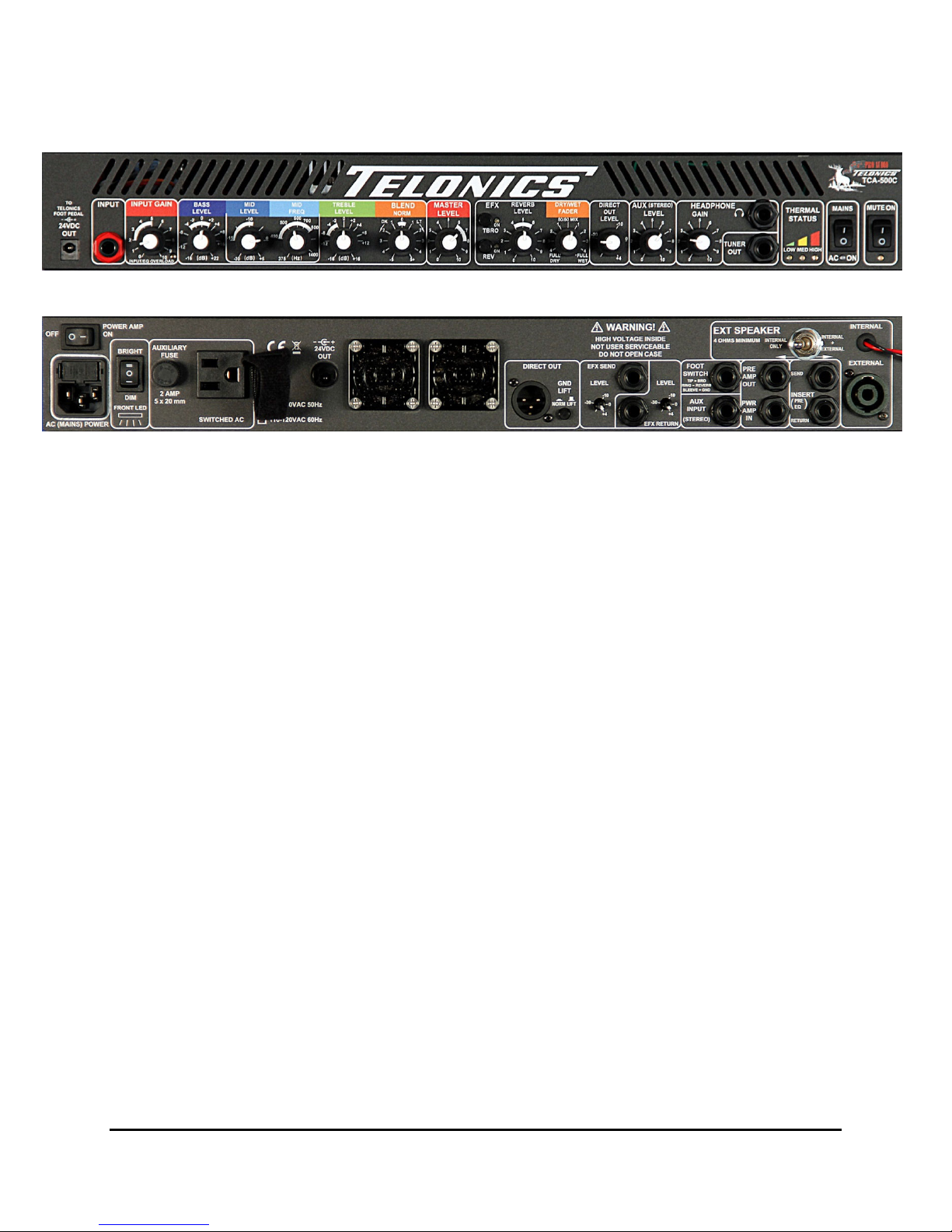
TCA-500C C
Fuse
OMBO AMP CONTROL FUNCTIONS & JACKS
R
EAR PANEL
:
Power Amp
ON/OFF
AC (MAINS) Power
Input
Turns the power amplifier On and Off. A time delay is built into the audio
circuits to minimize “pop” when turning On or Off. Note: The preamp is still
operational when the PA is off.
The Power Amp ON switches the Power Amp On/Off. It does not affect the
XLR Direct Out or the Headphones. When the Power Amp ON switch is Off
the cooling fans are disabled, after a few seconds, to minimize noise for use in a
studio.
This is an important professional feature for studio and live venue work using
the Direct Out from the Combo Amp. To use it, first establish your working
stage/studio volume through the combo speaker. Then turn the Power Amp OFF
and adjust your output level using the Direct Out level control on the front panel
to suit your taste (This will allow you to hear the house/studio system without
the local sound of your amp). Don’t forget to turn the Power Amp back ON
after this adjustment, as your cooling has been disabled while the PA is OFF.
Hint: If you ever find yourself at a live gig, trying to get sound from your
combo, but nothing is coming out, check this switch – someone may have
turned your power amplifier off! Your Temperature LEDs will be blinking in
groups of 3 blinks to warn you.
110-120VAC input*. Standard C13 plug on an 18 AWG cord is recommended.
The power input is fused with an 8 amp 250VAC 5x20mm ceramic Slow Blow
fuse.
*NOTE: Standard versions are wired for domestic use only. Export units are available on special
order. Export AC Power Input range is 170-240 VAC, 50-60 Hz with an 8A 250VAC fuse.
CAUTION: Voltages outside this range could damage the unit and cause a shock hazard.
Telonics TCA-500C Combo Amp
PB-009289 Rev E
22
Page 23

TCA-500C C
Fuse
AC (MAINS) Power
Input (cont.)
Front LED Light
OMBO AMP CONTROL FUNCTIONS & JACKS
R
EAR PANEL (CONTINUED
)
:
WARNING - Before checking this fuse ALWAYS ensure the
combo is disconnected from the mains supply.
Main Fuse (rear) – The AC mains protection fuse is located on the
rear panel. It is in a fuse drawer directly above the AC mains power
cord socket. Use a small screwdriver to release the spring latch on
each side of the drawer to release the fuse drawer.
If tests / a visual inspection of this fuse indicate it is open circuit,
take caution, your combo may have developed a fault.
ONLY replace the fuse with the EXACT type – Ceramic 8 Amp:
5 x 20mm: 250 Volt.
Note: If the fuse should blow immediately after being replaced DO
NOT try it again, this could cause more damage; return the combo
to Telonics for testing and repair.
The Front LED Light switch is a three-position toggle switch which turns
the Front panel LED illumination system to one of the following
conditions:
“Bright” “Off” or “Dim”.
Telonics TCA-500C Combo Amp
PB-009289 Rev E
23
Page 24

TCA-500C C
Fuse
Switched AC
Outlet Socket and
Auxiliary Fuse
(rear panel)
24 VDC OUT
(Combo Model)
(Head Unit Model)
9 VDC OUT
(Mini-Combo
Models Only)
OMBO AMP CONTROL FUNCTIONS & JACKS
R
EAR PANEL (CONTINUED
)
:
WARNING - Before checking this fuse ALWAYS ensure the
combo is disconnected from the mains supply.
Switched 110-120VAC outlet, fused with a 2 amp 250VAC 5x20mm
glass Slow Blow fuse. Note: This outlet is a C14 connector in the export
version.
To allow the combo to be powered from a single AC cord, a
switched AC power socket is provided to power up an external
effects unit.
WARNING – Mains voltage is present on this connection – DO
NOT plug in any device into this socket other than those that accept
the AC mains voltage. If any liquid is spilled on the combo in this
area UNDER NO CIRCUMSTANCES should the combo be used,
and the AC mains cord plug should be IMMEDIATELY
disconnected from the AC mains supply socket.
The output voltage from the Switched AC socket will be the same as
applied to the combo AC mains cord plug. Always check to be
certain that your effects processor voltage suits the supply voltage
applied to the TCA-500C Combo Amplifier.
Note: the power taken by the effects processor should not exceed 50
Watts.
This jack is in parallel with the 24VDC Out on the front panel. The power
supply is isolated from the main amplifier and can supply 0.2 amps
maximum. Note: Center pin is Positive (+).
This jack is available to provide 9 volts (regulated) DC power (1.0 amps
maximum) for external effects units which the user might wish to use with
the Mini-Combo Models.
Note: center pin is Negative (-) to comply with “stomp box
convention” standards.
Telonics TCA-500C Combo Amp
PB-009289 Rev E
24
Page 25

TCA-500C C
Fuse
Switched AC
Outlet Socket
Export version
(rear panel)
24 VDC OUT
(Combo Model)
(Head Unit Model)
9 VDC OUT
(Mini-Combo
Models Only)
OMBO AMP CONTROL FUNCTIONS & JACKS
R
EAR PANEL (CONTINUED
)
:
Switched 170-240VAC outlet, fused with a 2 amp 250VAC 5x20mm
glass Slow Blow fuse. Note: This outlet is a C14 connector in the export
version shown above.
To allow the combo to be powered from a single AC cord, a
switched AC power socket is provided to power up an external
effects unit.
WARNING – Mains voltage is present on this connection – DO
NOT plug in any device into this socket other than those that accept
the AC mains voltage. If any liquid is spilled on the combo in this
area UNDER NO CIRCUMSTANCES should the combo be used,
and the AC mains cord plug should be IMMEDIATELY
disconnected from the AC mains supply socket.
The output voltage from the Switched AC socket will be the same as
applied to the combo AC mains cord plug. Always check to be
certain that your effects processor voltage suits the supply voltage
applied to the TCA-500C Combo Amplifier.
Note: the power taken by the effects processor should not exceed 50
Watts.
This jack is in parallel with the 24VDC Out on the front panel. The power
supply is isolated from the main amplifier and can supply 0.2 amps
maximum between both connectors. Note: Center pin is Positive (+).
This jack is available to provide 9 volts (regulated) DC power (1.0 amp
maximum) for external effects units which the user might wish to use with
the Mini-Combo Models.
Note: center pin is Negative (-) to comply with “stomp box
convention” standards.
Telonics TCA-500C Combo Amp
PB-009289 Rev E
25
Page 26

TCA-500C C
OMBO AMP CONTROL FUNCTIONS & JACKS
R
EAR PANEL (CONTINUED
)
:
Direct Out
XLR
Direct Out
GND Lift
EFX Send Level
EFX Send Jack
EFX Return
EFX Return Level
Buffered post effects, post EQ signal for studio or stage use.
Output impedance = 600 ohm.
the standards for audio. Pin 1 is shield, Pin 2 is signal plus, and
Pin 3 is signal minus. The Direct Out Level control is on the front
panel. The range of the control is approximately -60dB to +4dB.
This switch allows you to disconnect Pin 1 of the XLR connector
from the chassis ground. It is seldom necessary in properly built
equipment, but might be needed sometime. Leave in the Norm
(In) position unless needed.
This adjusts the level to your effects unit. This will allow you to
have enough of a signal to make the effects work well and yet not
overdrive it.
Mono send to parallel mode effects unit input. Use a ¼ inch TS
(tip, sleeve) mono phone plug.
This is a mono (TS) input from your effects unit mono output.
This potentiometer allows you to select the nominal signal level
coming from your effects unit, it is adjustable from +4dB to less
than -30dB. Most “Pro” equipment is usually +4dB while
consumer equipment is usually -10dB.
The XLR connector is wired to
Telonics TCA-500C Combo Amp
PB-009289 Rev E
26
Page 27

Foot Switch
Aux Input
(Stereo)
TCA-500C C
OMBO AMP CONTROL FUNCTIONS & JACKS
R
EAR PANEL (CONTINUED
)
:
The Foot Switch jack on the rear panel may be used to switch the TBro and/or
the internal Reverb effects circuit on and off. A ¼ inch TRS (tip, ring, and
sleeve) stereo plug is needed. The sleeve is common, tip is TBro and ring is
reverb. The switch will enable the effects in the closed position.
Note that the type of switch to be used must ‘not’ be a momentary contact type,
but rather a continuously on or off type, such as a toggle switch.
The Auxiliary Input on the rear panel accepts a ¼” stereo or monaural
plug and may be used to inject audio from a CD, MP3 player or other
line level source, for home practice or live gigs. Use the Aux (stereo)
Level control on the front panel to set the desired music level.
The Aux Input provides a secondary input to the amplifier that sums into
the system such that it can be heard via the headphones, main speaker and
XLR Direct Out. The Aux Input is a stereo ¼” TRS Jack input; signals
fed via this input in stereo will remain in stereo when fed out to the stereo
Headphones jack. Signals fed via this input are summed to a mono signal
before being fed to the speaker and XLR Direct Out.
This input can be used in one of three ways:
i) A CD / MP3 Player connected to the Aux Input will allow tracks to be
played for practice and small gigs.
ii) An additional effects processor output can be returned via this input.
iii) A guitar effects unit output can be connected into this input, enabling
the amplifier to be used for both steel and guitar.
Note; this input is optimised for a 0dB line level signal.
Note; Signals applied to the Aux Input will be analog modelled when
output from the Direct Out.
Telonics TCA-500C Combo Amp
PB-009289 Rev E
27
Page 28

TCA-500C C
Preamp Out
Power Amp Input
OMBO AMP CONTROL FUNCTIONS & JACKS
R
EAR PANEL (CONTINUED
)
:
The Preamp Out jack is a line level output from the preamplifier section
of the TCA-500C that can be used to send the fully processed signal to
another power amplifier, powered speaker, etc.
Using a standard guitar cable with 1/4 inch TS mono plugs on both ends,
this jack can be used to treat this TCA-500C as a “Master” unit, which
can control a second TCA-500C as a “Slave – thus providing a total of
1000 watts of total amplifier power (500 per unit).
(Note that when this is done, a ground lifting device such as a HUM-X
must be used on the “Slave” unit in order to prevent a loud and
unpleasant ground loop hum.)
The Power Amplifier Input accepts line level signals from another source
to the power amplifier and local speaker in the TCA-500C Combo
Amplifier. When used, this jack will disconnect the internal preamplifier
signal from going to the Power Amp. Only the external signal coming in
on the TS mono plug will be amplified through the speaker.
PRE OUT / PA IN (jacks, rear) – Theses jacks allow two
TCA-500C combo’s to be slaved together. Connect a lead from the
Pre Out of the Master combo (The combo that the guitar is plugged
into) to the PA In of the Slave combo. The output from the speaker
of the master and slave combo’s will now be the same. When
adjustments are made to the master combo controls both combos’
outputs will be affected.
(Note that when this is done, a ground lifting device such as a HUM-X
must be used on the “Slave” unit in order to prevent a loud and
unpleasant ground loop hum.)
Telonics TCA-500C Combo Amp
PB-009289 Rev E
28
Page 29

Input 1 Gain
TCA-500C C
OMBO AMP CONTROL FUNCTIONS & JACKS
R
EAR PANEL (CONTINUED
)
:
Pre EQ Insert
Send
Pre EQ Insert
Return
This insert send follows the
may
be used as a pedal loop or a series effects loop.
control on the front panel. It
This insert return is prior to all of the effects and equalization circuits.
This includes TBro, Hum, Reverb, Wet/Dry fader, and all of the Input
Tone controls.
Telonics TCA-500C Combo Amp
PB-009289 Rev E
29
Page 30

TCA-500C C
OMBO AMP CONTROL FUNCTIONS & JACKS
R
EAR PANEL (CONTINUED
)
:
Ext Speaker
Internal (Red and
Black)
External
NOTE:
With the switch in the Internal Only position, the Internal (Black & Red wires)
speaker is all that is used. In the Internal + External position, the external
speaker is placed in series with the internal 4 ohm speaker.
This is the bridged output to the speaker. This output is active in both switch
positions. The internal speaker impedance must be greater than 3 ohm.
The red wire is (+) or positive phase, the black wire is (-) or negative phase.
CAUTION: Both wires have an audio AC voltage on them. DO NOT allow
them to short to ground when the amplifier is on, as this could cause a failure.
NEVER use grounded equipment to measure the speaker output.
This jack (combination Speakon or ¼ inch TS) is used to connect to the external
speaker. The ¼ in TS plugs into the center hole of the Speakon jack. The
external speaker is only active when the switch is in the Internal + External
position.
We recommend using a 4 ohm external speaker. (You can use an 8 ohm or even
a 16 ohm external speaker; however the volume level from the external speaker
will be slightly lower than the internal speaker.)
Telonics TCA-500C Combo Amp
PB-009289 Rev E
30
Page 31

TCA-500C C
OMBO (ONLY) AMP CONTROL FUNCTIONS & JACKS
R
EAR PANEL (CONTINUED
)
:
The Combo Amp unit has the 24 volt DC output and the Ext Speaker option.
24VDC OUT
Connector
Ext Speaker
The isolated 24 volt output uses the same connector as the 9 volt option, but the
center pin is (+) positive and the outer ring is (-) negative. The 24 volt output is
more common for external EFX units, such as The Handy Patch remote MIDI
Controller. The 24 volt supply on the rear panel is in parallel with the front
connector and the common supply can supply up to a total of 0.2 amps of
current maximum for both connections.
With the switch in the Internal Only position, the Internal (Black & Red wires)
speaker is all that is used. In the Internal + External position, the external
speaker is placed in series with the internal 4 ohm speaker. (See more details on
the previous page.)
Telonics TCA-500C Combo Amp
PB-009289 Rev E
31
Page 32

TCA-500C 15” M
INI-COMBO (INTERNAL SPEAKER) AMP CONTROL FUNCTIONS
& J
ACKS: REAR PANEL
The Mini-Combo Amp unit has the 9 volt DC output and External Speaker option.
-9VDC OUT
Connector Option
Ext Speaker
The isolated 9 volt output uses the same connector as the 24 volt option, but the
center pin is (-) negative and the outer ring is (+) positive. The 9 volt output is
more common for “stomp” box effects units, which a lot of Mini-Combo users
are used to. The 9 volt supply can supply up to 1 amp (1000mA) of current.
With the switch in the Internal Only position, the Internal (Black & Red wires)
speaker is all that is used. In the Internal + External position, the external
speaker is placed in series with the internal 4 ohm speaker. (See more details on
page 29.)
Telonics TCA-500C Combo Amp
PB-009289 Rev E
32
Page 33

TCA-500C 12” M
INI-COMBOS (WITH EXTERNAL SPEAKER) AMP CONTROL FUNCTIONS
& J
ACKS: REAR PANEL
The 12 inch 8 ohm TCA-500B Mini-Combos have a 9 volt DC output and built in speaker wire
with an additional Speakon connector for connection to a parallel external 8 ohm speaker.
-9VDC OUT
Connector Option
External Speaker
Output Option
(Standard MiniCombo amps are
supplied with 4
ohm Telonics NEO
Speakers)
The isolated 9 volt output uses the same connector as the 24 volt option, but the
center pin is (-) negative and the outer ring is (+) positive. The 9 volt output is
more common for “stomp” box effects units, which a lot of Mini-Combo users
are used to. The 9 volt supply can supply up to 1 amp (1000mA) of current.
The Mini-Combos can, as an option, have an internal 8 ohm 12 inch speaker
connected using the Red and Black wires. With the 8 ohm speaker option, this
allows for an external 8 ohm speaker to be used in parallel. The Speakon
connector allows you to use a ¼” jack in the center or use a regular Speakon
connector to connect the external 8 ohm speaker. As indicated on the rear panel
the minimum total speaker load impedance must be greater than or equal to 4
ohms. Two 8 ohm speakers in parallel equal 4 ohms. An 8 ohm and a 4 ohm
speaker in parallel equal 2.67 ohms which is too low an impedance load.
Telonics TCA-500C Combo Amp
PB-009289 Rev E
33
Page 34

TCA-500C H
EAD UNIT (ONLY) AMP
R
EAR PANEL
CONTROLS F
UNCTIONS & JACKS
:
)
The Head unit has the 24 volt DC output and a Speakon Connector only.
24VDC OUT
Connector
Speaker Output
The isolated 24 volt output uses the same connector as the 9 volt option, but the
center pin is (+) positive and the outer ring is (-) negative. The 24 volt output is
more common for external EFX units, such as The Handy Patch remote MIDI
Controller. The 24 volt supply on the rear panel is in parallel with the front
connector and the common supply can supply up to a total of 0.2 amps of
current maximum for both connections.
The Head Amp Speaker Output only has a combo Speakon connector for
the speaker connection. A ¼” plug can be used in the center connection
of the jack or a standard Speakon plug to connect to your speaker. The
minimum impedance is 4 ohms.
Telonics TCA-500C Combo Amp
PB-009289 Rev E
34
Page 35

TCA-500C C
The EQ settings shown above are suitable as a starting point for users who desire a more general
setting for all styles with middle-to- slightly darker tonal coloration.
As stated earlier, the MID frequencies are the key. Turning the MID Frequency control slightly
clockwise will reduce highs further.
You may also want to pull the Middle frequencies down a bit further toward -14 or -15 dB if the
Mids are still too “”in your face” with your pickup.
Once the equalization is set to your satisfaction, the BLEND control can be rocked slowly while
striking a wide grip of strings repeatedly to accurately “fine tune” all the EQ settings at one time.
Remember that these controls are sensitive, so a little adjustment can change a lot.
OMBO AMP SETUP SETTINGS
G
ENERAL USE SETTINGS
:
M
AXIMUM CLARITY SETTINGS
The EQ settings shown above are suitable as a starting point for users who desire a very crisp
and sharp, setting with very high definition of both lows and highs. This type of setting is bright
and clear (with good pickups in your guitar), and optimizes both the “growl” on the lower strings
and the “bells” on the high strings.
As stated earlier, the MID frequencies are the key. Turning the MID Frequency control slightly
clockwise will reduce highs further.
Once the equalization is set to your satisfaction, the BLEND control can be rocked slowly while
striking a wide grip of strings repeatedly to accurately “fine tune” all the EQ settings at one time.
Remember that these controls are sensitive, so a little adjustment can change a lot.
Telonics TCA-500C Combo Amp
PB-009289 Rev E
35
Page 36

TCA-500C C
These EQ settings, with only slight variations, are used by a number of professional musicians to
“cut through the mix” in live band applications.
Sonically, it is designed to “fit” in the “pocket” above the bass and low keyboards and below the
strings, providing clarity to the steel without clashing against the other orchestral elements. As
such, it may appear brash, or too “out in front” when playing with little or no accompaniment.
However in live applications, when used with the proper pickups, cables and volume pedal, it
can sit well in the mix and provide a live sound reminiscent of Push-Pull guitars at their best. It is
generally fine-tuned by moving the BLEND control plus or minus one mark on the dial either
way.
Once the equalization is set to your satisfaction, the BLEND control can be rocked slowly while
striking a wide grip of strings repeatedly to accurately “fine tune” all the EQ settings at one time.
Remember that these controls are sensitive, so a little adjustment can change a lot.
A
NOTHER FAVORITE SETTING FOR SOME PROFESSIONAL PLAYERS
OMBO AMP SETUP SETTINGS: (CONTINUED
M
ORE AGGRESSIVE SETTING
)
These settings are favored by a number of leading musicians. While projecting well in solo
performances, they provide an extremely full bodied sound with bell-like clarity and superb
string separation with most pickups.
Once the equalization is set to your satisfaction, the BLEND control can be rocked slowly while
striking a wide grip of strings repeatedly to accurately “fine tune” all the EQ settings at one time.
Remember that these controls are sensitive, so a little adjustment can change a lot.
Telonics TCA-500C Combo Amp
PB-009289 Rev E
36
Page 37

TCA-500C T
The cooling system for the TCA-500C Audio Amplifier consists of two variable-speed fans and
an intelligent digital controller circuit. The speed of the fans is determined by the temperature at
multiple key points within the amplifier. The controller is designed to run the fans at the slowest
possible speed sufficient to maintain the amplifier at a safe operating temperature, and thus yield
the quietest possible operation. As the temperature of the amplifier increases, the fan speed is
increased as necessary.
HERMAL MANAGEMENT SYSTEM
I
NTRODUCTION
N
ORMAL COOLING MODE
T
EMPERATURE INDICATION
The amplifier’s temperature is indicated on the front panel via the status LED’s:
Green = Temperature is above the Low temperature threshold
Yellow = Temperature is above the Medium temperature threshold
Red = Temperature is above the High temperature threshold
The following table shows the state of the Green, Yellow and Red LED’s, and the fan speed for
the specified temperature ranges:
Temperature LED Status Fans
>= < Green Yellow Red No.
Low Wink off off 1 Minimum
Low Medium ON off off 2 Increasing
Medium High ON ON off 2 Increasing
High ON ON ON 2 Maximum
F
AN SPEED OUT OF SPEC INDICATION
The speed of the fans is measured continuously in order to make sure that the fans are operating
properly and to assure adequate cooling for the amplifier. If the speed of any of the fans is out of
allowed tolerance for five or more consecutive seconds, then the LEDs defined by the above
table (i.e., Green and Yellow for temperature between Medium and High) will blink long flashes
twice per second; they will be On for ¼ second, and Off for ¼ second. This is a flash that is
easily discernible from the ‘Wink’ condition described above. If the speed of the fans returns
back to within tolerance, the blinking will stop, and the LEDs will return to the state described in
the table above. Should this ‘Flashing’ persist, this could be indicative of a fan failure, and could
lead to the amplifier overheating. In this case, the amplifier should be returned to the factory for
repairs.
Speed
:
Notes:
‘Wink’ = short blink, once
per sec.
‘ON’ = on solid.
Telonics TCA-500C Combo Amp
PB-009289 Rev E
37
Page 38

TCA-500C T
In order to further minimize the noise produced by the fans, and to prolong the life of the fans,
the fans are controlled individually. Whenever the temperature of the amplifier is below the Low
temperature threshold, one of the fans is turned off, and one fan continues to run at the minimum
speed. In most environments, when the amplifier is idle or played at lower levels, a single fan is
adequate to maintain a desirable temperature within the amplifier. Whenever the amplifier
temperature rises above the Low threshold, the second fan is turned on in addition to the first
one; therefore, both fans will be running, initially at the minimum speed. Should the temperature
of the amplifier continue to rise, the speed of both fans will be increased accordingly; if the
temperature of the amplifier drops, the speed of both fans is reduced accordingly. If the
temperature of the amplifier again drops below the Low threshold, then the second fan is turned
back off. The fan which will ‘always be On’ is alternated every time that the AC mains power is
cycled. Thus, in the long run, the wear on the fans will be balanced.
To enable the studio mode, turn the Power Amp On/Off switch to the “Off” position. The Power
Amp switch is located on the rear panel, just above the AC (Mains) power cord socket.
In the Studio mode, the power amplifier is switched off and the fans are not turned on. In this
mode, the LEDs blink a special pattern to alert the user to the fact that the unit is in this mode,
the power amplifier is off, and to indicate the temperature of the amplifier. The blink pattern is
three (3) short blinks (winks) followed by a short pause, and then repeat. For added visual
emphasis, in later model amplifiers, this pattern is supplemented by all three LEDs blinking three
(3) times; alternating with the temperature display indication.
The amplifier’s temperature is indicated on the front panel via the status LEDs:
Green winking
Green and Yellow winking
Green, Yellow, and Red winking
HERMAL MANAGEMENT SYSTEM (CONTINUED
FAN-W
S
TUDIO (NO FANS) MODE
T
EMPERATURE INDICATION
EAR BALANCING
:
Temperature is below the Medium temperature
threshold
Temperature is above the Medium temperature
threshold
Temperature is above the High temperature
threshold
)
Telonics TCA-500C Combo Amp
PB-009289 Rev E
38
Page 39

F
REQUENTLY ASKED QUESTIONS
What’s a good setting to start with on the Gain control?
An initial setting of “3”is a good starting point. The Input Gain control delivers plenty of level
so be cautious to avoid the red overload (“clipping”) LED from coming on.
What are the frequencies covered by the Mid Freq control? Mid Level?
The “Mid Freq” control has a range from 375 Hz to about 1400 Hz. The range is scaled to values
of, 375, 400, 500, 600, 700, 800 and 1400 Hz. The “Mid Level” control adjusts from -20 dB cut
at full CCW position to a +5 dB boost at full CW position.
What does the Blend control do?
This control is used as an overall “fine” tone control to be used only after setting the other tone
controls to your satisfaction. Rotating the knob clockwise yields a brighter more aggressive tone
and counterclockwise results in a mellower, warmer tone. Straight up (zero) yields no change.
What’s a good setting to start with on the Master Level control?
A setting of “5” is a good place to start. This level will be determined by the size of the room
you are playing in. The Master Level control delivers plenty of level so be cautious in its use.
What kind of headphones should I use?
Use low impedance (35-60 ohm) stereo closed or open style depending on personal preference.
Sony MDR 7505 headphones are recommended for best fidelity.
Can I drive speakers with the headphone jack?
No, only use it for headphones. It was designed for headphones. The preamp will deliver up to
half a watt per channel into eight ohm from its internal stereo headphone amp.
What does the red LED overload indicator show?
The Overload LED shows when the preamp enters (or is about to enter) soft clipping. Although
you might see it light up on rare occasions, you’ll probably never hear the difference.
indicates an overload on the input or equalizer circuits. Reduce gain or adjust EQ of input to eliminate
blinking.
This LED
Tell me about the Tuner Out function.
The Tuner Out jack has a buffer stage and circuitry which isolates the output of the tuner from
the rest of the circuitry eliminating a common source of external noise sometimes emanating
from some tuners. This circuit will not load down other circuitry in the TCA-500C. The Tuner
Out can also be used as an effects Send.
What does the Mute button do?
When engaged, the mute function allows the tuner, headphone amp, and effects send and return
to remain On while the preamp out and XLR direct out feed are disabled. This way you can
practice at home or in between songs on stage without your power amp On and still get a stereo
feed to your headphones complete with stereo effects. Use it to mute your output while
changing a string, tuning up, running through upcoming licks or adjusting the effects unit.
Telonics TCA-500C Combo Amp
PB-009289 Rev E
39
Page 40

F
REQUENTLY ASKED QUESTIONS
(C
ONTINUED
)
Will pushing the Mute button send a loud “pop” into my speakers, headphones or
the XLR Direct Out (the house feed) when I activate it?
No, the preamp employs silent muting circuitry.
How do I use the Aux In feature?
The Aux In may be used to input stereo rhythm tracks or background music from CD or MP3
players. The Aux In feature can also function like a second stereo effects return. It can be used
as a way to inject practice music into the main channels and/or headphones or to add a second
effects return. The amount of music or effects level is determined by the output level of the
music or effects player and the Aux In Level control. All audio connected to the Aux In is fed to
the Direct Output connector for PA and recording purposes.
Can I safely run phantom power into my Direct Out circuit?
While it is not necessary (nor a good idea) to run phantom voltage into the Direct Out connector,
it is designed to withstand the IEC specified maximum of 10 milliamps without damage.
What output level can I expect to see from the Direct Output connector?
Normally, the output is approximately the same as the main outputs, up to 5 volts maximum,
however it can be controlled by the user in real-time by using the Direct Output control on the
front panel. This control allows the DO output to be set from mic level (-30 dBu), to high line
level (+4 dBu).
This is very handy when a sound man pre-sets your level on the board too low and leaves for a
while. Normally, you would be stuck. By using this control, you can simply reach over, set your
house volume through the PA board, and hopefully, not start a “sound war” when he returns to
the booth…..
Telonics TCA-500C Combo Amp
PB-009289 Rev E
40
Page 41

(Optional) E
XTERNAL CONTROL UNITS
TCA-500C R
An External Control Unit which clips on the
leg of a pedal steel is available to control the
Reverb and TBro effects within the
TCA-500C Combo Amplifier, as well as to
Enable or Disable the EFX “engines” in the
Lexicon MX-200. It provides two toggle
switches, one for turning the Reverb On and
Off, and a second for turning the TBro effect
On and Off.
C
ONTROLLING THE
B
UILT-IN EFFECTS
Note that the TBro and Reverb
pushbutton switches on the front
panel of the TCA-500C must be ON
(pushed in) in order for the remote
unit to function.
These switches are located on the right side
of the box as viewed from the player’s
position. The TBro On/Off switch is
positioned on the upper right corner of the
front panel.
The Reverb On/Off switch is positioned on
the lower right corner of the front panel.
A ¼ inch TRS stereo cable is required to connect the TCA-500C side of the Control Unit to the
“Foot Switch” jack on the rear panel of the TCA-500C. This cable is identified by a white ring
around the cable directly behind the TRS stereo plugs on both ends. Always be sure the cable
with the white ring markings is fully inserted into the bottom right side of the Control Unit, with
the TRS stereo plug on the other end plugged into the Foot Switch jack on the rear panel of the
TCA-500C.
One way to remember this is to recall the rhyme used by cardiac technicians in hospitals for their
EKG leads:
“White on the Right”.
(NOTE: A two-button foot pedal switch is also available from Telonics which accomplishes the
same remote switching functions for the TCA-500C. A single ¼ inch TRS stereo cable is used to
connect the foot pedal switch unit to the Foot Switch jack on the rear panel of the TCA-500C.)
EMOTE UNIT OR FOOTSWITCH FOR USE WITH LEXICON
TCA--500C
EFX UNITS
MX-200
Telonics TCA-500C Combo Amp
PB-009289 Rev E
41
Page 42

(O
PTIONAL) EXTERNAL CONTROL UNIT (CONTINUED
C
ONTROLLING THE LEXICON
MX-200
)
The External Control Unit provides two (2) momentary push button switches which may be used
to either ENABLE (UN bypass), or DISABLE (bypass) the two effect “engines” in the Lexicon
MX-200 effects unit.
A second ¼ inch TRS stereo cable is required to connect the Lexicon MX-200 side of the
External Control Unit (the LEFT side). The cable for this connection is all black in color. Be sure
this cable is fully inserted into the bottom LEFT side of the Remote Control Unit, with the TRS
stereo plug on the other end of the cable plugged into the FOOTSWITCH jack on the left side of
the rear panel of the MX-200 EFX unit.
The two ¼ inch TRS stereo cables used for connection are available from Telonics.
Momentarily depressing these two buttons does exactly the same thing as depressing the two
BYPASS buttons on the front panel of the MX-200. You can determine the status by looking at
the LED indicators within the BYPASS buttons on the MX-200.
The controls for the two (2) effects processors in the MX-200 are grouped together in adjacent
rectangular “boxed” areas on the front panel of the MX-200. Each “box” contains a BYPASS
button in the upper right corner, three control/function/parameter knobs, a tempo button and a
UP/DOWN toggle switch which is used to select the desired effect (which that particular
processor “engine” will be generating.
Processor Number 1 is on the LEFT. Its BYPASS button has a GREEN LED in it. This
processor is normally used to generate DELAYS and similar effects.
Processor Number 2 is on the RIGHT. Its BYPASS button has a RED LED in it. This processor
is normally used to generate REVERBS and similar effects.
NOTE!
It is necessary to comprehend that when the LED in a given BYPASS button is ON,
that processor is BYPASSED, meaning that the effect being generated by that
process is OFF! I.E., when a given BYPASS button LED is ON, the effect is OFF!
The two buttons on the LEFT side of the External Control Unit control these BYPASS buttons
just as if you actually pushed the buttons on the MX-200 themselves. The STATUS of the
BYPASS buttons (and therefore the status of the effects processors in the MX-200) is indicated
by the colored LED within the button on the MX-200.
The UPPER/BLACK button on the External Control Unit controls Processor #1 (Green BYPASS
LED on the MX-200).
The LOWER/RED button on the External Control Unit controls Processor #2 (RED BYPASS
LED on the MX-200).
Telonics TCA-500C Combo Amp
PB-009289 Rev E
42
Page 43

(O
PTIONAL) EXTERNAL CONTROL UNITS
HANDY PATCH
The Handy-Patch can be attached to the leg of a
steel guitar using the Mounting Bracket and
Swivel accessory as shown in the photos.
The Handy-Patch (HP) is an industry first, special
purpose, MIDI controller designed specifically to
interface the steel guitar player with MIDIenabled effects processors mounted in the 1U rack
space of the Telonics TCA-500 series combo and
head-only amplifiers.
It is supplied in the form of a small box which
mounts quickly and easily on the leg of a steel
guitar and is connected by a dedicated MIDI cable
assembly to the TCA-500 amplifier and the
effects processor (which has been previously
programmed with a selection of combined
effects). These effects may be instantly called
up/’loaded’ by selecting a ‘preset’ number (note
that a ‘preset’ may also be referred to as a ‘patch’
or ‘program change’).
The Handy Patch uses the music industry standard
MIDI connection to send information to the
effects processor. A display on the front indicates
the number of the preset which has been selected.
Two push-buttons allow the Present number to be
increased, decreased or rapidly scrolled up and
down.
Two Additional buttons allow two Fast-Presets to
be selected. When a Fast-Preset is selected, the
unit instantly calls up a previously selected preset.
When that same Fast-Preset button is pressed
again, it instantly returns to the originally selected
preset. For example; when used with the TC
Electronics G-Major 2 effect processor, this
allows the player to instantly toggle from the
current preset to the TBro effect preset rapidly
within the performance and back again.
MIDI C
ONTROLLER
MC100
Telonics TCA-500C Combo Amp
PB-009289 Rev E
43
Page 44

(O
PTIONAL) EXTERNAL CONTROL UNITS (CONTINUED
H
ANDY PATCH
A third Fast-Preset can be selected by using an
optional (not supplied) momentary contact
footswitch which can be plugged into the Handy
Patch. This allows a predetermined effect patch to
be selected and de-selected (toggled), without the
player needing to take his or her hands away from
the instrument.
In addition to sending the MIDI Preset
information, the HP can also control parameters
within the effects processor using the Control
Change (CC) knob/wheel on the front panel.
For example; when used with the G-Major 2
effects processor, this allows the player to control
the effect level of the preset selected and change that level during the performance. In addition,
the CC knob value can be stored by simply pressing the knob so that the next time that preset is
called up; it will have the stored effect level applied.
Note: The Handy-Patch can also be used with the Lexicon MX-200 effects unit and by using
defaults, will select presets when the Lexicon MX-200 has been set to MIDI channel 1. (The HP
transmits commands on MIDI channel 1, so the MX-200 must also be set to channel 1.) The CC
Knob can also be programmed to access the available control change functions if required.
Note: the CC function can be disabled if the user prefers not to use this control or finds it
confuses their effects unit of choice.
Accessories available for a Handy-Patch system:
1) Handy-Patch MIDI Controller - model MC100
2) Handy-Patch to TCA-500C 7-pin MIDI cable assembly – MC100/7PIN-LEAD1
3) Mounting bracket and Swivel Assembly
4) Footswitch, Fast Preset 3 – Not yet available
MIDI C
ONTROLLER
MC100
)
Telonics TCA-500C Combo Amp
PB-009289 Rev E
44
Page 45

(O
PTIONAL) EXTERNAL CONTROL UNITS (CONTINUED
H
ANDY PATCH
(B) 16 inch long ¼ inch TRS
A) The Handy Patch comes with a cable (A above) to connect to the TCA-500C. On one end
is a five pin DIN connector with a pigtail power connector. This five pin DIN connects to
the G-Major 2 MIDI IN jack. The pigtail power connector should be plugged into the
24VDC jack as shown in the picture above. The other end of the cable has a seven pin
DIN connector that plugs into the Handy Patch. The Handy Patch will now turn on when
the TCA-500C is powered up.
B) The G-Major 2 has a Switch Out jack on the back that uses internal relays to switch the
Tip or the Ring terminal on the jack to the Sleeve (ground). This output will allow the GMajor 2 to control the Foot Switch input jack on the TCA-500C, which controls the
internal Reverb and TBRO effects. A ¼ inch TRS cable (B above) should be connected
between the Switch Out jack on the G-Major 2 and the Foot Switch jack on the
TCA-500C as shown in the picture above.
MIDI C
(A) Handy Patch cable
ONTROLLER
MC100
)
NOTE: See the Handy Patch User’s Manual for more detailed
information.
Telonics TCA-500C Combo Amp
PB-009289 Rev E
45
Page 46

U
SING SMALL “STOMP BOX” EFFECTS UNITS WITH THE
A
MPLIFIERS
TCA-500
SERIES
TCA-500 M
INI-COMBO MODELS
The Telonics TCA-500 Mini-Combo amplifiers do not offer a 1U rack space in order to conserve
weight and space. They are equipped with minimal internal effects.
It is therefore sometimes desirable to add one or more additional effect(s) using small, special
purpose 9 Volt “Stomp-Box” effects units. A proper series mode insert for connecting such
effects units is provided in the form of the “Pre-EQ” Insert/Pedal Loop on the rear panel.
In addition, a dedicated 9 Volt power supply is included in the TCA-500 Mini-Combo
Amplifiers specifically for this purpose. The EFX power jack is located on the rear panel of the
amplifier. It provides 9 Volts DC, at up to 1amp (1,000 mA). The jack is wired in accordance
with the stomp box de facto standard; CENTER PIN IS NEGATIVE (-), outer barrel positive
(+).
ALWAYS check the polarity required by your external effects unit before plugging it into
power.
By using the stomp boxes in this manner, the user is able to connect his/her guitar’s signal
directly to the input of the TCA-500 Amplifier and enjoy the clarity and string separation
provided by the internal studio grade preamplifier, as well as, to establish the noise figure prior
to introducing the processing propagation time loss and A/D & D/A conversion noise inherent in
such stomp boxes.
Most “Stomp box” or effects “pedal” units should be connected using the “Pre-EQ Insert”/Pedal
Loop on the rear panel of the TCA-500 series amplifiers. Such effects units are of the type;
BOSS RV3, RV5, Strymon DIG, Digitech Polara, Holy Grail, Holy Grail Nano, Strymon Flint,
TC Electronic Hall of Fame Reverb, Mr. Springy, Z-Cat, etc.
To connect a single 9Volt “stomp box”:
First, connect a short ¼ inch TS cable from the SEND output to the INPUT of the effects unit.
(If you are using a STEREO effects unit, use the MONO jacks.)
Then using a second short ¼ inch TS cable, connect the OUTPUT of the effects unit to the
RETURN jack of the Pre-EQ Insert.
When all signal connections have been made and checked, connect the effects unit to the (-) 9 V
power jack on the rear panel of the TCA-500 Mini-Combo amplifiers.
If you wish to connect more than one 9 Volt effects unit; for example, delay, followed by
reverb, you may connect multiple units in series within the Pre-EQ Insert Loop.
To do so, connect a short ¼ inch TS cable from the SEND output of the Pre-EQ Insert to the
INPUT of the first effects unit. (If you are using one or more stereo effects unit, use the MONO
jacks.)
Then using a second very short ¼ inch TS cable, connect the OUTPUT of the first effects unit to
the INPUT of the second effects unit.
Last, using a third short ¼ inch TS cable, connect the OUTPUT of the second effects unit to the
RETURN jack of the Pre-EQ Insert.
Telonics TCA-500C Combo Amp
PB-009289 Rev E
46
Page 47

When all signal connections have been made and checked, connect the (-) 9 V power jack on the
rear panel of the TCA-500 Mini-Combo amplifiers to the effects pedal using the provided power
cable.
Note that some “Stomp Box” effects pedals are designed to accept only very low-level signals
(such as guitar output only). Such units must therefore be installed between the user’s volume
pedal and the input of the TCA-500 amplifier. Overdrive – Type Stomp pedals are typically
installed in this manner.
NOTE:
All of the above and similar “pedals” are designed for “series” connection. This means that they
mix together in varying degrees, the original “dry” sound of your guitar, with the “wet” or
processed sound (reverb, delay, etc.).
As such, they MUST be used in the Pre-EQ Insert Loop and are NOT SUITABLE to be
inserted in a Parallel Effects Loop.
To be suitable for use in a parallel effects loop, an effects unit must have a fully
PARALLEL mode, which means that it is FULLY WET – no dry sound must be allowed to
pass through, at all. (If any dry signal is passed through such an effects unit, it is delayed
due to the digital processing time required by the analog-to-digital and the digital-to-analog
converters within the effects unit – it’s just a fact of life, it takes a certain amount of time to
do these necessary conversions.
Then, when this delayed dry signal is mixed back with the pristine, clean dry signal which
was not sent out to the effects unit, phase cancellation occurs at various frequencies, which
forms a “comb” filter whose peaks and nulls are a function of the delay required in each
individual delay unit (so it will vary from unit to unit).
The resultant sound can vary from OK to horrible, depending on the effects unit and the
frequencies played through the amplifier.
That is why all high-end effects are set to “parallel mode” only, and connected to the
parallel effects loop of studio equipment, and the TCA-500 series amplifiers.
“Fully wet” stomp boxes” may” be available; however after testing many, we are not aware of
even one we can recommend at this time.
TCA-500 C
OMBO AND HEAD-ONLY MODELS
Normally, small stomp box effects units are not used with TCA-500 Combo and Head-only
Amplifiers since they are provided with a 1U rack space to accommodate full-on professional
effects units and the Handy-Patch remote MIDI controller.
Nonetheless, in the event that the user wishes to stomp box effects units with these models, they
should be connected in the manner described above for the TCA-500 Mini-Combo Amplifiers.
However, the user must be aware that these models DO NOT provide a 9 VDC power source for
stomp box effects units. Rather, they offer 24 VDC for the Handy-Patch remote MIDI controller.
(This 24 VDC output jack may alternatively be used as a second power source for Telonics
model FP-100 foot volume pedals.)
NOTE that the 24 VDC output jack on these models is wired CENTER PIN POSITIVE (+),
outer barrel negative (-).
Telonics TCA-500C Combo Amp
PB-009289 Rev E
47
Page 48

H
OW TO BE A TONE MASTER – SUBTRACTIVE EQUALIZATION
The following information from the great audio engineer John LeMay is an
important and insightful key to achieving well-balanced sound with ideal tone.
How to Be a Tone Master
by John LeMay
This is a collection of thoughts on how to get the best tone you can through what might seem to
be an unconventional way of doing it. This information comes from my years of mixing and
mastering experience in Hollywood.
Subtractive equalization: The Art of attenuating, rather than boosting, frequencies to achieve
equalization.
When first trying to get "that sound", your tendency may be to push something up. Where you
might feel like you need to add some high end, you may actually just need to cut at 200Hz to
clear the sound up. Then you can add a dB or two at the top end, and it will sound as open as
adding 6dB or 8dB of high-frequency EQ.
Excessive EQ can mask perception of audio nuance and detail. When frequency buildup
becomes extreme — particularly in the upper midrange, where the ear is most sensitive — subtle
space-enhancing details are the first to fall victim to frequency masking and hearing fatigue.
As more additive EQ (boosts as opposed to cuts) gets piled on, the final result is often grating,
tinny, or downright unlistenable at moderate volume. Such an excessive buildup — in addition
to hastening listening fatigue — may smear or obscure subtler aspects you’re playing. The
interaction of compression or reverb in this range further compounds the problem.
EQ should almost always be used as a subtractive device. That means, use it primarily for
lowering certain frequencies in a pre-amp. Every mix or amp sound usually has too much of
something to begin with." Too much bottom end, too many high's, mids are honkin'.
Use EQ to lower those trouble spots. Result . . . Cleaner sound, better sound. Simple, isn't it?
EQ should be subtle - not drastic. Boosting the EQ also has a tendency to raise the noise floor.
In subtractive EQing you are pulling down the level of a given frequency. In additive EQing you
are raising the level of the chosen frequency. For example, say you're in the studio and you have
an acoustic guitar track that sounds too “muddy”. Your first instinct may be to raise the
frequencies around 4kHz to brighten up the sound a bit. But you are better off pulling down the
low-mid frequencies around 325Hz instead!
Here's a simplistic example of how to do it. Say you want more high-end. First bring down the
low end a bit, and then raise the overall (master) gain to compensate for the gain loss. This has
the effect of raising the high end but without increasing noise. Go back and forth between
lowering the bottom end and replacing gain with the master level control till you achieve the tone
you are looking for. Practice this till it becomes second nature. Raising the bottom end is done
in much the same way. First bring down the high end a bit, and then raise the overall (master)
gain to compensate for the gain loss. This effectively raises the bottom end EQ. This requires
careful listening to know how much to cut and how much master gain to compensate with.
Telonics TCA-500C Combo Amp
PB-009289 Rev E
48
Page 49

H
OW TO BE A TONE MASTER – SUBTRACTIVE EQUALIZATION
C
ONTINUED
For midrange, I cheat a bit and boost it slightly in the frequency I wish to affect. I then lower the
high and low EQ till I achieve the midrange sound I am looking for. A little goes a long way.
Practice, practice, practice.
Watch out for the low end. Too much energy in the bottom octaves (below 300 Hz) will mask
the higher frequencies and cause you to want to add more highs. You'll end up chasing your tail
running after the perfect tone.
When it comes to using EQ, "Less is more".
Telonics TCA-500C Combo Amp
PB-009289 Rev E
49
Page 50

T
ELONICS TILT-BACK FOOT
A special Telonics – designed Tilt-Back Foot is provided on the following Models:
TCA-500B&C & Combo Amps
TCA-500B&C Mini-Combo Amps
External Speaker Cabinets for TCA-500B&C Mini-Combos
The Tilt-Back Foot is designed to tilt the
amplifier slightly backward to enhance
visibility of the control panel. To deploy
the Foot, rock the amplifier backward and
pull downward on the tip of the foot until
it locks into place.
To retract the foot, rock the amplifier
backward sufficiently to remove any
weight on the foot. Push the tip of the Foot
back and upward until it is heard to snap
into its cavity on the bottom of the
amplifier cabinet.
Do Not Attempt to Stand on the
Amplifier Cabinet with the Foot
Deployed!
Telonics TCA-500C Combo Amp
PB-009289 Rev E
50
Page 51

TCA
-
500C Combo
M
Feature Specification
ECHANICAL DATA
Electronics Chassis
Hard Anodized Aluminum
Material
Front & Rear Panel
Lexan Surface
Markings
Cabinet
The cabinet is made from multi-ply Baltic Birch, 12mm
& 15mm thick continuous panels that are dove tailed
together for maximum strength. Then sprayed with
urethane to make a hard, extremely durable finish.
Dimensions See Outline Drawing page
Total weight
speaker & No 1U external effects unit
TCA-500C Mini-15 Combo – 33.7 lb. (15.286 kg) With
15 inch speaker
TCA-500C Mini-12 Combo - 28.6 lb. (12.973 kg) With
12 inch speaker
TCA-500C Head Unit – 12.8 lb. (5.806 kg)
– 34.2 lb. (15.513 kg) With 15 inch
Telonics TCA-500C Combo Amp
PB-009289 Rev E
51
Page 52

E
LECTRICAL DATA
Parameter Condition Value
Mains input voltage
115 V ac setting (factory set) 85 V ac to 132 V ac
US Model
Mains input voltage
230 V ac setting (factory set) 170 V ac to 250 V ac
Export Model
Mains fuse
115 V ac and 230 V ac
setting
Auxiliary switched AC power
outlet fuse
Auxiliary switched AC power
115 V ac and 230 V ac
setting
115 V ac US Model
outlet
Auxiliary switched AC power
230 V ac Export Model
outlet
Preamp Gain 1 kHz sine
Power Amp Gain 1 kHz sine
Output power @ 1%THD+N RL = 4 Ohm
8 A 250 V ac 5x20mm
Ceramic Slow Blow fuse.
2 A 250 V ac 5x20mm glass
Slow Blow fuse
NEMA 5-15R
IEC-320 C-13
58 dB typical
30 dB typical
300 W rms typical
Output power @10%THD+N
(Max power 500 W)
20 Hz < f > 20 kHz, both
channels driven
115 V ac
RL = 4 Ohm
20 Hz < f > 20 kHz, both
channels driven
115 V ac
400 W rms typical
Telonics TCA-500C Combo Amp
PB-009289 Rev E
52
Page 53

TCA-500C 15-1U COMBO
MECHANICAL OUTLINE DRAWINGS
Telonics TCA-500C Combo Amp
PB-009289 Rev E
53
Page 54

TCA-500C 12-1U COMBO
M
ECHANICAL OUTLINE DRAWINGS
Telonics TCA-500C Combo Amp
PB-009289 Rev E
54
Page 55

TCA-500C 15-MINI COMBO
M
ECHANICAL OUTLINE DRAWINGS
Telonics TCA-500C Combo Amp
PB-009289 Rev E
55
Page 56

TCA-500C 12-MINI COMBO
M
ECHANICAL OUTLINE DRAWINGS
Telonics TCA-500C Combo Amp
PB-009289 Rev E
56
Page 57

MINI-15 EXTERNAL SPEAKER ENCLOSURE
M
ECHANICAL OUTLINE DRAWINGS
Telonics TCA-500C Combo Amp
PB-009289 Rev E
57
Page 58

MINI-12 EXTERNAL SPEAKER ENCLOSURE
M
ECHANICAL OUTLINE DRAWINGS
Telonics TCA-500C Combo Amp
PB-009289 Rev E
58
Page 59

TCA-500C 212 SUPER TWIN COMBO
M
ECHANICAL OUTLINE DRAWINGS
Telonics TCA-500C Combo Amp
PB-009289 Rev E
59
Page 60

TCA-500C-1U HEAD UNIT
M
ECHANICAL OUTLINE DRAWINGS
Telonics TCA-500C Combo Amp
PB-009289 Rev E
60
Page 61

TLF-PRE500 LITE-FLIGHT PREAMPLIFER SYSTEM
M
ECHANICAL OUTLINE DRAWINGS
Telonics TCA-500C Combo Amp
PB-009289 Rev E
61
Page 62

Telonics TCA-500C Combo Amp
PB-009289 Rev E
62
 Loading...