

TEL-MAR DLC-7000 Series Handbook

DVB
equipment handbook
DIGITAL COFDM
CAMERA LINK
DLC- 7000 Series

DLC-7000 SERIES
COFDM CAMERA LINK

WARNING:
Before making any action towards the equipment, please read
carefully the entire manual, paying attention to all the notes!
All data, information and specification contained in this document may be
changed without prior notice.
TEL-MAR accepts no responsibility for errors or omissions.

Table of contents
Page
Chapter 1: General information
............................................................................................ 6
1.1 - Propriet ar y information .................................................................................................................. 6
1.2 - Common conve nt i on s ................................................................................................................... 6
Chapter 2: General conditions of warranty
................................................................. 7
2.1 - Conditions of received goods ......................................................................................................... 7
2.2 - Warranty ......................................................................................................................................... 8
Chapter 3: General safety instructions
............................................................................ 9
3.1 - Certifi c at i on s ................................................................................................................................... 9
3.2 - Qualifi ed personnel ......................................................................................................................... 10
3.3 - Safety instructions ........................................................................................................................... 10
3.4 - Proper installation, use and maintenance of TEL-MAR equipments .................................................
..
12
Chapter 4: Equipment’s description
.................................................................................. 14
4.1 - Description .................................................................................................................................... 14
4.1.1 - Transmitter .......... ... ...... ... ... ...... ... .. ... ...... ... ... ...... .. ... ...... ... ... ...... .. ... ... ...... ... ... .................... 14
4.1.2 - Receiver..................... ...... ... ... ...... ... .. ...... ... ... ...... ... .. ...... ... ... ...... ... .. ...... ... ...... ..................... 14
4.1.3 - Antennas............................................................................................................................. 14
4.1.4 - Carrying case and accessories..................... ...... ....... .......................................................
14
4.2 - Features
and applications ............................................................................................................. 15
4.3 - Technical da ta ............................................................................................................................... 16
4.4 – Receiver Control Pannel.................................................................................................................. 18
4.5 - Front pa nel
Rx
................................................................................................................................ 19
4.6 - Right panel
Tx
…............................................................................................................................. 20
Chapter 5: Unpacking the equipment
............................................................................... 22
5.1 - Damages due t o tr an sp or t ............................................................................................................ 23
5.2 - Box contents ................................................................................................................................. 23
Chapter 6: Installation
.................................................................................................................. 24
6.1 - Operating environment feat ur es ................................................................................................... 24
6.2 - Ambient c har act eri sti c s ................................................................................................................. 25
6.3 - Instructions for installation ............................................................................................................ 25
6.4 – Some recommendations ............................................................................................................ 26

Page
Chapter 7: Use
................................................................................................................................... 28
7.1 - Starting up the equipments ........................................................................................................... 28
7.2 - Controls descri p ti on ...................................................................................................................... 29
Chapter 8: Transport and storage
....................................................................................... 30
8.1 - Transport ...................................................................................................................................... 30
8.2 - Storage ......................................................................................................................................... 30
Chapter 1
General information
Chapter 1: General information
1.1 Proprietary information
This manual contains information protected under Copyright of TEL-MAR.
All rights are reserved.
This manual shall not be reproduced or photocopied, in whole or in part, without the written
permission of TEL-MAR. Use of the Manual and the information which it contains is permitted
only by the Customer to whom it has been supplied, comprising a kit supplied with the
relevant equipment. This documentation is to be used only for installation, operation and
maintenance of the TEL-MAR equipment to which the manual refers.
1.2 Common conventions
Notes
Attention
Notes highlighting important information out of the related text.
Notes designated Attention refer to those procedures whose non
observance can cause damage to the equipment itself and / or other
equipments connected to it.
Danger
Safety notes indicate those procedures which is essential to follow in
order to ensure maximum safety to personnel.
Page 6

Chapter 2
General conditions of warranty
Chapter 2: General conditions of warranty
2.1 Conditions of received goods
All TEL-MAR ’s equipments are fully tested electrically and inspected mechanically
before despatch ex-works. It therefore meets or exceed its electrical specifications and is
free of mechanical defect at that time. Prior to transportation and shipment, all goods are
factory packed as appropriate and suitable for the method of transport (air, ship or road
vehicle) using either wooden crates or strong cardboard boxes or containers. Lifting
palettes are normally attached to crates or heavy boxes.
Attention: packed goods in transit should be protected from severe
shock or extreme weather conditions and from undue dust or heat,
otherwise damage to the equipment may result, leading to subsequent
malfunction
Before installing the equipment, please verify:
◊
The integr i t y of th e pa c k i n g ch a s s is. The box must not be damaged.
◊
The integrity of the shipped goods. The equipments must not be damaged.
◊
Verify that all the parts that make up the equipment are contained in the box.
Page 7

Chapter 2
General conditions of warrant y
2.2 Warranty
The following are the terms under which TEL-MAR provides a warranty or guarantee
for all equipments supplied:
TEL-MAR ’s warranty lasts for 12 months from the shipping date, cover parts and labour
required to repair subunits or replace components. Repairs under warranty are effected
free of charge, except for the associated freight charges both to and from the factory of
TEL-MAR in Fara Gera d’Adda (Italy), which ar e th e re sponsibility of the customer.
Conditions of warranty
◊
TEL-MAR ’s warrant y deca y s for parts or co mponents whic h fail fo r any reaso n
attrib u t able to external causes or
misuse of any kind.
In the event of any malfunctioning being discovered during the
warranty period, TEL-MAR ’s technical office must be contacted
before attempting any repair, replacement of parts or recalibration
of the equipment and in order to seek guidance. This is
imperative for preserving validity of warranty.
◊
It is desirable that a written failure report is produced by a responsible person and that a
copy accompanies the returned part to TEL-MAR .
Failure to observe any of the instructions or recommendations in the
Manual for installation, operation or maintenance of the equipment or
any unorthodox testing or unauthorised tampering with it at any time, wi ll
automatically invalidate the warranty.
◊
Parts excluded from warranty are:
¬
tubes (valves): since these parts are directly warranted by the manufacturers with their
own terms and conditions.
¬
semiconductors: if the failure is not caused by other parts or units covered by
TEL-MAR warranty.
In any cases of doubt about the failure, TEL-MAR technical office should be contacted
without delay. TEL-MAR reserves the right to refuse warranty for failures which have not
been reported within a reasonable period of time.
Page 8

Chapter 3
General safety instructions
Chapter 3: General safety instructions
3.1 Certifications
The equipment described in this Manual has been designed and manufactured by TELMAR to satisfy the essential quality and safety requirements foreseen by the following
European Directives, in the case of being part of a complete TEL-MAR transmitter:
◊
Low Voltage 93 / 68 / CEE (modified fro m 73 / 23 / CEE).
◊
Electromagnetic compatibility 89 / 336 / CEE and follow i n g modifications up to 1998.
If the equipment is intended to be used stand alone, it is considered as a subunit, for which it
doesn’t need any CE certifications. In this case the equipment has imperatively to be used
with an isolating transformer with earthed screen shot, with an AC line filter, in the confines of
a shielded room.
If the transmitter (or transposer) is to be used as a part of a transmitter different f rom those
manufactured by TEL-MAR , it will be care of the customer to verify that the complete system
will satisfy the current legislation for safety and electromagnetic compatibility, in the
country where it will work.
TEL-MAR requests all users of the equipment to follow exactly the instructions, procedures
and recommendations contained in this Manual, and to do so in accord with current
Health and Safety at Work legislation in the country of use.
TEL-MAR assume no responsibility for injury to p ersons, animals or
damage to property, however caused, which stems from any breach of
the rules or recommendations given in this Manual.
Page 9

Chapter 3
General safety instructions
3.2 Qualified personnel
All installations, operations and maintenance of TEL-MAR ’s equipment shall be carried out
only by Staff who have an appropriate recognised engineering qualification and who have
read the information contained in this manual.
It is assumed that Staff so qualified will have the necessary knowledge and practical
experience in electronics and radio engineering to evaluate the risks which can occur
working on the equipment, and also, to take suitable safety precautions to avoid injury or
damage to Staff itself or other persons.
TEL-MAR assume no responsibility for injury to persons, animals or
damage to property, however caused, which stems from the actions of
staff or other personnel who are not suitably qualified and experienced
as above.
3.3 Safety instructions
For the safety of installation, operational and maintenance personnel, and to help avoid
danger at all times, the following simple rules should be observed:
◊
TEL-MAR equipment shall be connected to the AC supply mains in ways which are
consistent with current local legislation for the installation of electrical wiring and with
curren t local requirements for saf e t y and sec u rity in the wo rk pl a c e.
◊
TEL-MAR equipments shall first be earthed by connections of its frame or earth busbar / terminal to a substantial protective ground or external earthing point provided for
the purpose, by means of a conductor of appropriate cross section, consistent with
current legislation (or Codes of Practice) for protection against electrical shock and
Safety at Work.
◊
An automatic circuit breaker with residual current detector (RCD) or differential circuit
breaker shall be installed on the supply side and in series
with the AC supply subcircuit
feeding TEL-MAR equipment, having a suitable rating and leakage current
sensitivity, consistent with current local legislation.
◊
TEL-MAR equipment must be stored or installed in secure premises where access is
allowed only to persons specifically permitted by the responsible authority.
◊
Qualified maintenance engineers or technicians shall be cautioned not to open the
equipment or disconnect connectors or terminals without first isolating the complete
equipment from the electrical AC supply and any other power source.
Page 10

Chapter 3
General safety instructions
◊
All personnel likely to be on a Transmitting Si te shall be alerted to the dangers inherent
in transmitting antennas and dishes which are connected to TEL-MAR equipments.
These antennas emit radiofrequency radiation (non ionising). There is a high
concentration of power in the direction of the main beam of the transmitting antenna,
especially using high gain and / or high directivity antennas fed from high power
amplifiers.
¬
Every person on Transmitting Sites should be encouraged to take appropriate
precautions to avoid danger or injury to himself / herself and to other people; for
example by observing the following rules:
¬
Do not climb, or allow others to climb, a structure on which a transmitting antenna is
mounted without first ensuring that it is safe to do so and that the transmitter is
switched off and will remain so until personnel are off the structure.
¬
Do not climb over or through a working transmitting antenna under any circumstances.
¬
Do not look directly into an antenna from anywhere in the vicinity within the main beam
(or at all, if in doubt) and don’t use a telescope or binoculars; etc. for linin g up wi th a
transmitting antenna when under power. This is to protect the eyes against radiation.
¬
Do not cross the main beam (principal lobe) of a transmitting antenna in its vicinity.
¬
Do not bring close to a transmitting antenna, equipment which is likely to be damaged
by electromagnetic radiation from the elements of the antennas themselves, and do not
make measurements when near to an antenna underpowe r.
◊
Certain components may contain substances which can cause a toxic hazard under
certain conditions; for example, beryllium oxide used in high power semiconductors.
Normally these components can be handled without significant risk, but broken
components are hazardous if particles are allowed to be absorbed by the human body.
Any parts of the body coming into contact with such particles should be washed
thoroughly with water and treated by a medical doctor.
¬
Disposal of faulty components (whether broken or not) shall be done with the
component inside a sealed container and under the supervision of an approved local
agency or company specialising in remova l of toxic waste.
◊
For TEL-MAR equipments allowed in rack more than 5 units special care has to be
taken in handling and moving to avoid danger or injuries to personnel.
TEL-MAR assume no responsibility for injury to persons, animals or
damage to property, however caused, which stems from non observance
of any of the safety instructions and rules or procedures given above
Before making any maintenance of the equipment, remember to switch
off the unit and to verify the discharge of high voltage capacitors.
Page 11

Chapter 3
General safety instructions
3.4 Proper installation, use and maintenance of TEL-MARequipments
◊
TEL-MAR equipments shall be transported and stored according to the prescribed
information, which is given in this Manual.
◊
The AC supply line voltage shall be in accordance with the rated value and tolerance
stipula ted by the manufacturer ; generally within ±10% of the nomin al value specifi ed by
TEL-MAR , unless stated otherwise.
◊
If normal AC line voltage variations exceed this tolerance, it is essential to employ a
voltage stabiliser, or line conditioner.
◊
If there is likely to be instantaneous line over voltage; for example, transients caused by
electrical machinery connected to the same line, or by nearby electrical discharges,
lightning etc.; it is desirable to install a grounded screen shot isolating transformer to avoid
damage to the Equipment. It is also always recom mended to u se AC line surge protector s
to minimise lightning damage.
◊
TEL-MAR equipments are designed for indoor use, unless stated otherwise. So they
must be protected from rain, water or bad weather conditions. Variations of weather
conditions must not be too rapid and must be so slow to avoid forming of
condensate.
◊
For TEL-MAR equipment designed for indoor use, the ambient temperature where
equipment is used shall be within -10°C and +45°C, unless stated otherwise.
Operating the Equipment for long periods at high temperature (i.e. 40-45°C) greatly
reduces the lifetime of som e com ponents, so it is important to provide the Transmitter
area with forced air ventilation system. TEL-MAR ’s Technical Office is available to
suggest the most suitable air cooling system in particular cases.
◊
Dust and high humidity cause deterioration and damage to electronic equipment. It pays
therefore to give prepare the
area in which the Equipment is to be used by installing air
filters and adequate ventilation. This to avoid an excessive
degree of humidity or dust,
which will never exceed the specified limits.
Again, Customers may contact TEL-MAR ’s Technical Office for
suitable advice.
◊
Before switching on a Transmitter or Power Amplifier (even though VSWR protection is
fitted) the output connector shall be connected to a suitable load, antenna or to
successive equipment which has been tested and is ready to work.
◊
Antennas or loads shall have a VSWR better than 1.5:1 (14 dB return loss) unless
otherwise specified.
◊
TEL-MAR ’s equipments never can be used with output power higher than the nominal
one or with driving signals different
from those specified in the technical data
. Input
signal peaks higher that the ones specified can cause permanent damage to the
equipments.
Page 12

Chapter 3
General safety instructions
◊
High po wer am plifie rs, wh ether tubed or so lid state, shall not have RF drive po wer applied
when they are switched off (i.e., without DC power supply).
Periodical maintenance shall be carried out on the Equipment, including:
◊
Regular cleaning of air filters and heat sinks according to environmental conditions.
◊
Air blow er functionality
◊
Antenna voltage standing wave ratio at the main feeder input
◊
Output signal level and quality
TEL-MAR assume no responsibility for injury to persons, animals or
damage to property, however caused, which stems from non observanc e
of any of the preceding recommendations for Proper Use of the
equipment.
TEL-MAR technical office is always at Customers disposal for detailed
informations, instructions and suggestions.
Page 13

Chapter 4
Equipment’s description
Chapter 4: Equipment’s description
4.1 Description
The DLC-7000 series is t h e C O F D M digital r a d io camera link operating in band 2.0-2.5 GHz.
It is composed of the following units:
◊
Transmitter
◊
Receiver
◊
Antennas
◊
Carrying case and accessories
4.1.1 Transmitter
Transmitter is housed in a compact aluminium box with V-lock plates on two sides which allow
to hang it directly to the camera and to connect the battery to it’s back. The supply of the unit is
from the connected battery and it is passed through the transmitter to the camera too. On the
right side there are all the signal connections ant the connector for PC for setting of the
parameters, while the RF antenna connector is on the top.
4.1.2 Receiver
Receiver is housed in a compact aluminium rack or in PELI case depending on the model.
There is a large LCD monitor and a keyboard for control of the Rx parameters and received
signal. There are also all the signal and power supply connections. The receiver is also
available in the 19” 1U or 2U rack version without the monitor.
The receiver can be equipped with 2 ch, 4 ch or 6 ch diversity depending of the version.
Standard version is with 2 ch diversity.
The RF down convertors can be internal or external. Standard version is with internal down
convertors. If the convertors are external the power supply to the convertors is feed through
the same RF cable.
4.1.3 Antennas
Depending on the use that you need the you will be suggested the right antennas - from 15 dBi
to small 7 dBi omnidirectional antennas for the receiver and from 8 dBi to 5 dBi omnidirectional
antennas for the transmitter. In the particular conditions you can also use the directive
antennas.
4.1.4 Carrying case and accessories
The camera link kit is usually delivered with heavy duty sealed rigid case with foam interior for
safe transport and handling of the equipment. There are also RF cables, and eventual other
accessories necessary for the correct use of the equipment.
Page 14

4.2 Features and applications
Chapter 4
Equipment’s description
FEATURES
◊
The DLC-7000 offers the latest technology in a portable digital video & audio
transmission.
◊
The best quality MPEG-2 video, with the stereo audio, and COFDM modulation scheme
guarantee excellent performance.
◊
COFDM multi carrier modulation is immune to chroma breathing, picture break up and
other multipath reflection problems, which are a feature of analogue FM systems. In fact
COFDM benefits from multipath reflections. Robustness of the transmitted signal is also
greatly improved due to the Forward Error Correction.
◊
Enables non “line of sight” operation with a fixed receiving antennas.
◊
Receiver with diversity technology (2, 4 or 6 channel diversity can be used) for improved
coverage and signal quality.
◊
Over 1 km coverage in the urban area and over 4 km coverage in the line of sight with
only 500 mW transmitter (hand held camera on the shoulder).
◊
The system is ideally suited to mobile operations and its low weight, small size and
modular construction ensure the greatest degree of flexibility.
◊
Large colour LCD monitor on the receiver allows instant control of the received video and
audio signals and all reception parameters.
◊
Optional 1U or 2U 19” racks mount Rx for fixed installation in OB van or studio.
◊
Transmitter can be mounted in a back-pack with batteries and antenna for special
purposes or on the vehicles or helicopters (also with optional booster amplifier which
gives very extended operation range).
◊
Doppler compensation for speed up to 200 km/h.
◊
V-mount or Gold Plate fixing for battery and camera.
◊
With DLC-4500 central receivers you can obtain the cellular coverage of the large urban
areas - see dedicated brochure.
APPLICATIONS
◊
Broadcast and communications
◊
ENG and sport coverage
◊
City news and events coverage with fixed central receivers system - “cellular network”
◊
Used with live cams at sporting or cultural events
◊
Transmission of the live pictures from vehicles, boats or helicopters
◊
Police and authorities (mobile surveillance)
◊
Fire brigade and civil protection (live pictures on site)
◊
Security sector
◊
Military sector
Page 15

Chapter 4
Equipment’s description
4.3 Technical Data
TRANSMITTER SPECIFICATIONS
Power output
10-500 mW (up to 10 W with optional amplifier)
Modulation system
COFDM
Modulation
64QAM/16QAM/QPSK
Signal to noise ratio
>43 dB
DVB-T standard
ETSI EN 300 744 V 1.4.1 (2k mode)
Number of carriers
2k
Frequency band
2000 MHz – 2500 MHz in 0.25 MHz-steps
Signal bandwidth
6 ,7 or 8 Mhz
Forward Error Correction (FEC)
1/2, 2/3, 3/4, 5/6, 7/8
Encoding
ISO/IEC 13818-2 ML@MP (MPEG-2 4:2:0)
Transferrate
1,5 MBit/s – 15 MBit/s
Picture mode
low delay (P-frame only)
Supported resolutions
D1, HD1, SIF
Audio sampling
48 kHz, 44.1 kHz, 3 2 kH z
Video inputs
SDI (BNC), analog composite (BNC)
Video standards
PAL, NTSC, SECAM
Audio inputs
mini XLR, unbalanced, line or MIC level, optional SDI embedded audio
Control
via PC running dedicated software
Antenna
N female - omnidirectional - gain 7 dBi - other on request
Power supply
12-15 Vdc V-mount IDX plates - optional Gold Plate adapter
Current Consumption
1500 mA @ 12 Vdc
Operating temperature
-15°C to +60°C
Storage temperature
-40°C to +80°C
Weight
870 g
Dimensions
185×55×95 mm
Page 16

Chapter 4
Equipment’s description
RECEIV E R SPECIFICATIONS
Modulation system
COFDM
Demodulation
64QAM/16QAM/QPSK
Number of carriers
2K
Frequency band
2000 MHz – 2500 MHz in 0.25 MHz-steps
Signal bandwidth
6, 7 and 8 Mhz
Forward Error Correction (FEC)
1/2, 2/3, 3/4, 5/6, 7/8
Supported resolutions
D1, HD1, SIF
Video outputs
SDI (BNC), analog composite (BNC)
Video standards
PAL, NTSC, SECAM
Audio outputs
XLR, balanced, line level
Control panel
LCD colour monitor 7” (OSD + video and audio monitoring)
Antenna input
2 x N female
Rx antennas
omnidirectional vertical pol. - gain 15 dBi (other antennas on request)
Power supply
100-240 Vac 47-63 Hz or 12 Vdc
Current Consumption
1,2 A @ 12 Vdc
Operating temperature
-15°C to +60°C
Storage temperature
-40°C to +80°C
Weight
2.5 kg (depends on housing type)
Dimensions
320×270×170 mm (depend on housing type)
Page 17
Chapter 4
Equipment’s description
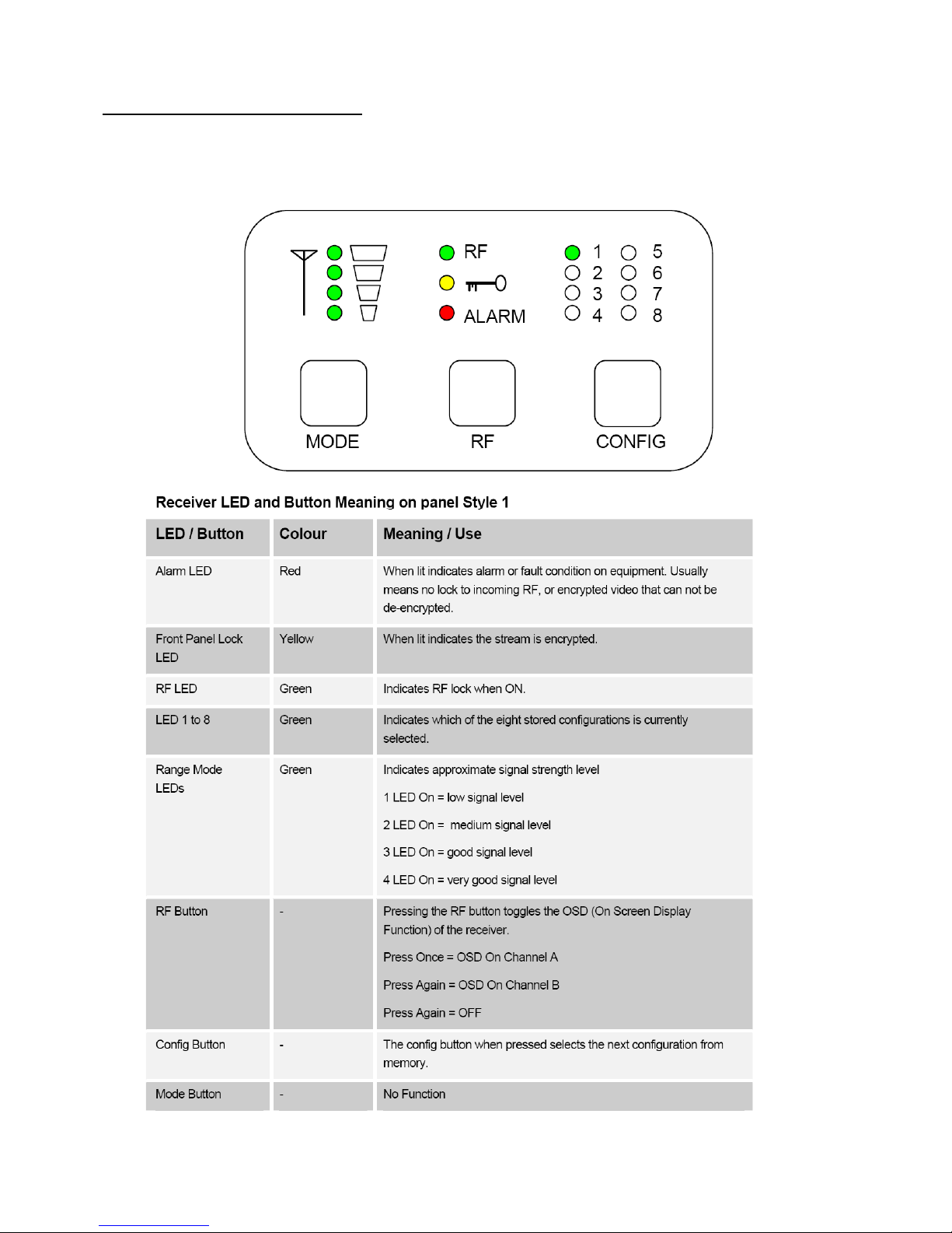
4.4 Receiver Control Panel:
DLC-7000 Series Receivers can be fitted with LED (Light Emitting
Diode) and push button panel depending on model type
Page 18
Chapter 4
Equipment’s description
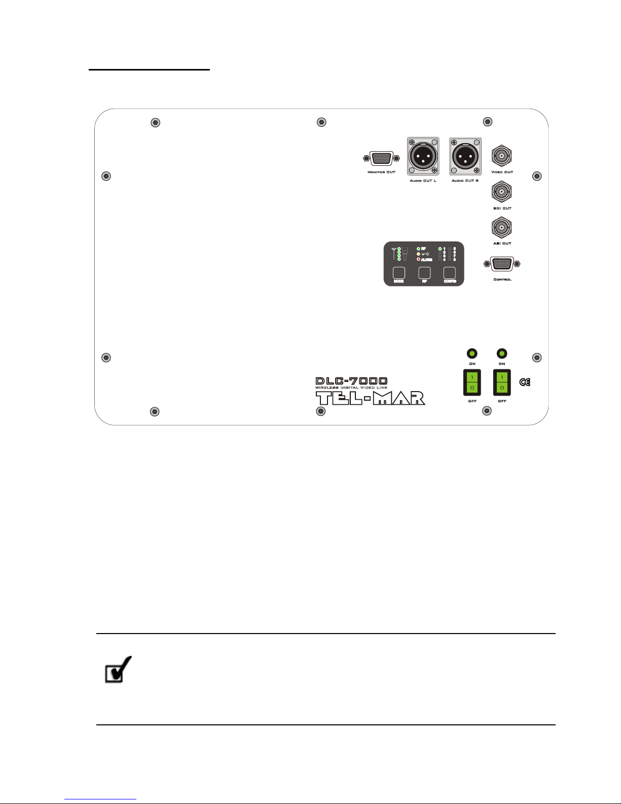
4.5 Front pannel Rx
Fig. 2
Rear panel
STANDARD PANEL CONNECTIONS CONFIGURA TIO N (* )
01) AC input and DC input (on right side of the box)
02) Mains switch 12 V dc and 220 Vdc
03) RS-232 (DB 9 female) remote control
04) Analog L EF T audio output (XLR male 3 pole)
05) Analog R IG H T audio output (XLR male 3 pole)
06)
SDI digital video
output (BNC female )
07) Composite video output (BNC female)
08) RF 1 input (N fe m ale ) – c o n ne ct io n to Rx an te nn a 1 (on right side of the box)
09) RF 2 input (N fe m ale ) – c o n ne ct io n to Rx an te nn a 2 (on right side of the box)
10) ASI serial transport stream output (BNC female)
11) Monitor out connector
* These are the connections of the standard panel; according to
the specific model and options installed, connections may vary. Please
see the silkscreen on the rear panel of the specific unit and/ or additional
documentation for the correct configuration of the connections.
Page 19
Chapter 4
Equipment’s description
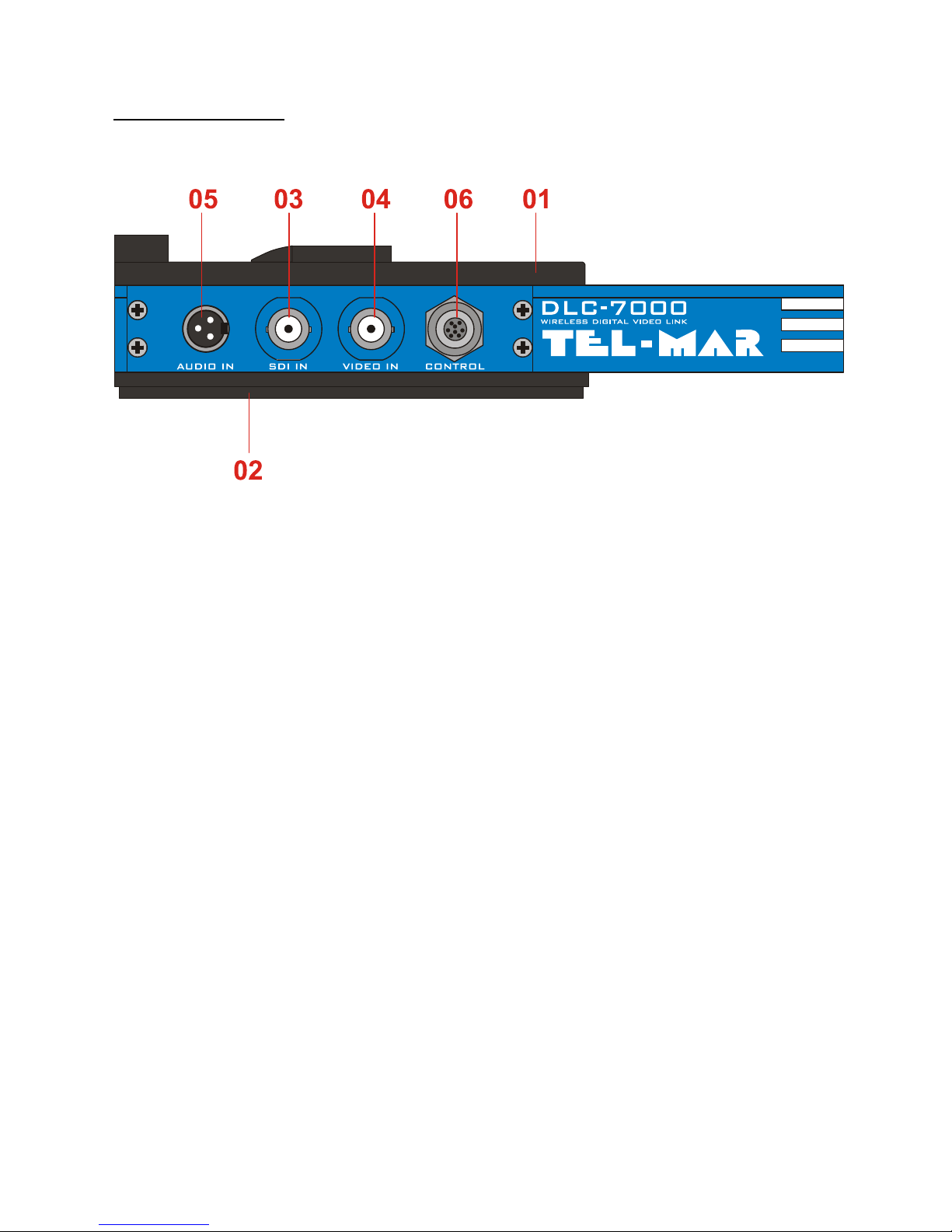
4.6 Right panel Tx
Fig. 3
Right panel
STANDARD RIGHT PANEL CONNECTIONS CONFIGU R AT I ON
01) DC input V-LOCK plate
02) DC output and hanging V-LOCK plate
03)
SDI digital video
input (BNC female)
04) Composite video input (BNC female)
05) Analog audio input L+R (mini XLR female 3 pole)
06) Control PC connection (8 pin female TYCO connector)
On the top side of the Tx there is :
RF output (N female) connection to the transmitting antenna
Power switch
Power LED
Page 20
Chapter 4
Equipment’s description
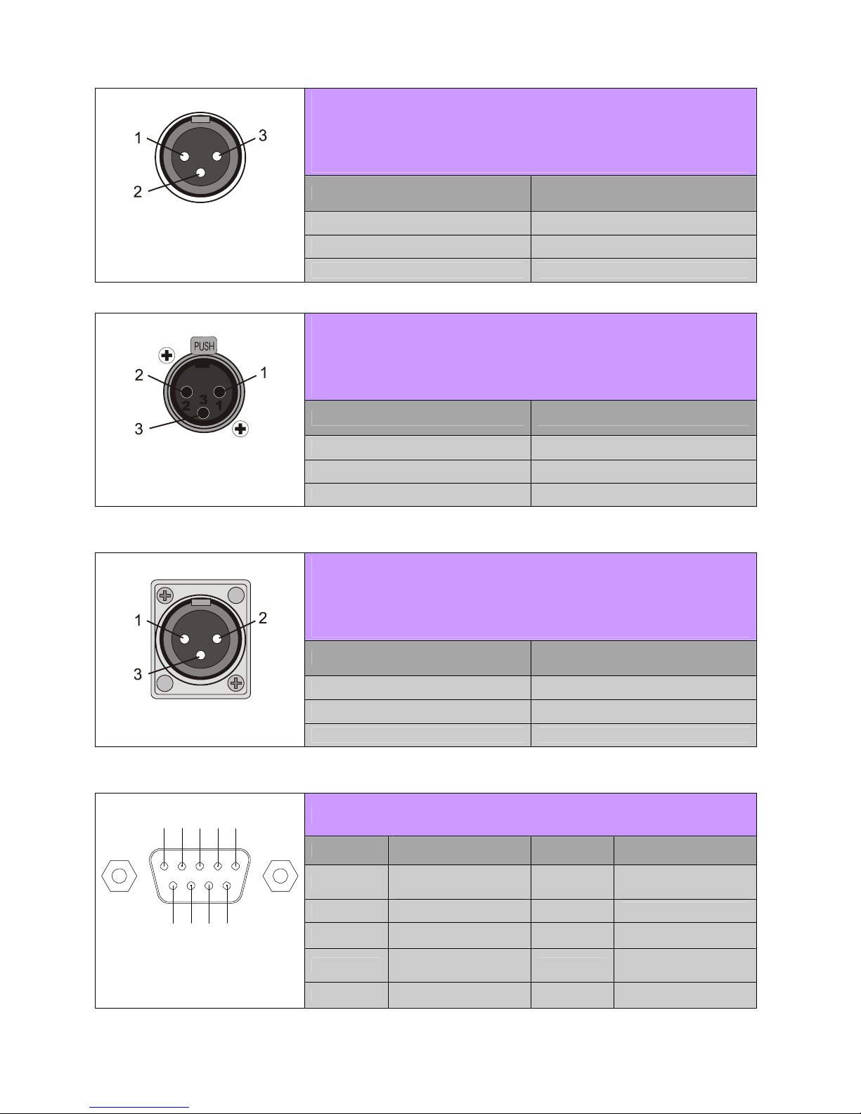
LEFT + RIGHT
ANALOG AUDIO INPUT
3-POLE MINI XLR CONNECTOR
PIN ASSIGNMENT
1
GND
2
AUDIO LEFT
3-pole mini XLR female connector –
front view
3
AUDIO RIGHT
LEFT OR RIGHT
ANALOG AUDIO INPUT
3-POLE XLR CONNECTOR
PIN ASSIGNMENT
1
GND
2
AUDIO +
3-pole XLR female connector –
front view
3
AUDIO – (or GND for unbal.)
LEFT OR RIGHT
ANALOG AUDIO OUTPUT
3-POLE XLR MALE CONNECTOR
PIN ASSIGNMENT
1
GND
2
AUDIO +
3-pole XLR female connector –
front view
3
AUDIO -
RS232 DB9 CONNECTOR
PIN ASSIGNMENT PIN ASSIGNMENT
1
DCD (or not
used)
6
DSR
(or not
used)
2
RX
7
RTS
(or not used)
3
TX
8
CTS
(or not used)
4
DTR
(or not
used)
9
Not used
5 4 3 2 1
9 8 7 6
DB9 female connector –
front view
5
GND
Page 21
 Loading...