

Page 1
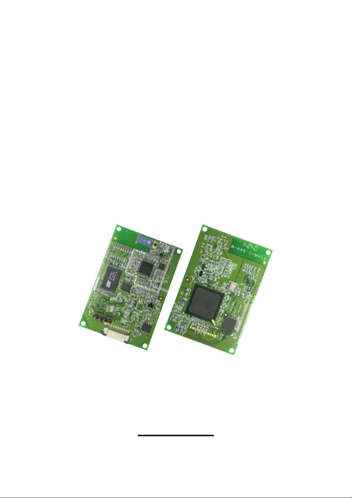
S103 WLAN Compact Serial Module
WLAN Compact Serial Module
OEM lnstallation Guide
S103
Version 1.0
Page 2
S103 WLAN Compact Serial Module Version 1.0
1
data error may cause death, injury or damage
WARNING - Disclaimer
Do not use this device in applications for
which any failure of the wireless link or any
of any ki nd.
Tellus Group Corp., its Sales, Manufacturing and Design Organizations, Reps., Distributors,
VARs and distribution channels are absolutely not liable for any death, injury, property
damage, loss of data, loss of business of any other unmentioned loss. The aforementioned
entities are not liable even in the event that any of these entities were apprized of the specifics
or generalities of an application or intended inst allation at any time.
Radio Linkages of any type can be fragile and tenuous. Over 1/5th of the entire population of
the world now owns cellular telephones, and as any user of a cell phone knows, the cell
phone radio communications link may be easily disrupted or completely lost simply by turning
your head or by other small environmental movements or changes. This clearly demonstrates
to everyone the fragility of any radio link and why radio should not be used for critical
implementations, or where death, personal injury, physical damage, property damage or
environmental damage may result.
Tellus Group Corp.’s products are not designed, manufactured, or intended for use or resale
as online control equipment in hazardous environments requiring fail-safe performance, such
as, but not limited to the operation of nuclear facilities, aircraft navigation, vital communication
systems, air traffic control, life support machines, weapons systems, or any industry in which
environmental disruptions or technology failure could lead directly to death, personal injury,
physical damage, property damage or environmental damage.
Page 3

S103 WLAN Compact Serial Module Version 1.0
2
Copyright © 2004 by manufacturer. All rights reserved.
No part of this documentation may be reproduced in any form or by any means or used to
make any derivative work (such as translation, transformation, or adaptation) without written
permission from the copyright owner. All the other trademarks and registered trademarks are
the property of their respective owners.
Statement of Conditions
The content described in this manual may be improved or changed at any time and it is
subject to be changed without notice.
Manufacturer assumes no responsibility for errors contained herein or for direct, indirect,
special, incidental or consequential damages with the furnishing, performance, or use of this
manual or equipment supplied with it, even if manufacturer of its suppliers have been advised
of the possibility of such damages.
Electronic Emission Notices
This device complies with Part 15 of the FCC Rules. Op eration is subject to the following two
conditions:
1. This device may not cause harmful interference.
2. This device will accept any interference received, including interference that may cause
undesired operation.
FCC Radio Frequency Interference Statement
This equipment has been tested and found to comply with the limits for a class B digital device,
pursuant to Part 15 of the FCC rules. These limits are designed to provide reasonable
protection against harmful interference when the equipment is operated in a commercial
environment. This equipment generates, uses, and can radiate radio frequency energy and, if
not installed and used in accordance with the instruction manual, may cause harmful
interference to radio communications. Operation of this equipment in a residential area is
likely to cause harmful interference in which case the user need to correct the interference at
his area. If the equipment causes interference to radio or television reception, try to correct
the interference by using one or more of the following measures:
l Plug the equipment into an outlet that is on a different circuit from the television or radio.
l Change the direction of the television or radio antenna until the interference disappears.
l Move the equipment to one side or the other of the television or radio.
l Move the equipment farther away from the television or radio.
To assure continued compliance, any changes or modifications not expressly approved by
manufacturer could void the user’s authority to operate the equipment.
Page 4

S103 WLAN Compact Serial Module Version 1.0
3
FCC Radiation Exposure Statement
This device and its antenna must operate with a separation distance of at least 20 cm from all
persons and must not be co-located or operating in conjunction with any other antenna or
transmitter. End users must be provided with specific operating instructions for satisfying RF
exposure compliance.
Regulatory information / Disclaimers
Installation and use of this Wireless LAN device must be in strict accordance with the
instructions included in the user documentation provided with the product. Any changes or
modifications (including the antenna) made to this device that are not expressly approved by
manufacturer may void the user’s authority to operate the equipment. The manufacturer is not
responsible for any radio or television interference caused by unauthorized modification of
this device, or the substitution or attachment of connecting cables and equipment other than
manufacturer specified. It is the responsibility of the user to correct any interference caused
by such unauthorized modification, substitution or attachment. Manufacturer and its
authorized resellers or distributors will assume no liability for any damage or violation of
government regulations arising from failing to comply with these guidelines.
Modular Approval
This device is intended only form OEM integrators under the following conditions:
1) The antenna must be installed such that 20cm is maintained between the antenna and users,
and
2) The transmitter module may not be co-located with any other transmitter or antenna.
IMPORTANT NOTE: In the event that these conditions can not be met (for example certain
laptop configurations or co-location with another transmitter), then the FCC authorization is
no longer considered valid and the FCC ID ca n not be used on the final product. In these
circumstances, the OEM integrator will be responsible for re -evaluating the end product
(including the transmitter) and obtaining a separate FCC authorization.
Page 5

S103 WLAN Compact Serial Module Version 1.0
4
End Product Labeling
This transmitter module is authorized only for use in devices where the antenna may be
installed such that 20 cm may be maintained between the antenna and users The final
end product must be labeled in visible area with the following:
"Contains TX FCC ID: PB6-04051¨
End Product Manual Information
The user manual for end users must include the following information in a prominent location
“IMPORTANT NOTE: To comply with FCC RF exposure compliance requirements, the
antenna used for this transmitter must be installed to provide a separation distance of at
least 20cm from all persons and must not be co-located or operating in conjunction with
any other antenna or transmitter.”
Page 6

S103 WLAN Compact Serial Module Version 1.0
5
**Statement:
The radio portion of this module has not been shielded. The module will be installed in the
OEM device only. OEM integrator should apply FCC certification after the module installed
to OEM device for meet FCC rules.
Limited W arranty
This product is warranted by manufacturer to be free from defects in material and
workmanship for one (1) year from the date of purchase unless otherwise stated.
During this period if this product is found to be defective in material or workmanship,
manufacturer or one of its authorized service facilities will at its option either repair or replace
this product without charge, subject to the following conditions, limitations and exclusions:
• This warranty extends to the original consumer purchaser only and is not assignable or
transferable.
• This warranty shall not apply to any product which has been subjected to misuse, abuse,
abnormal use, negligence, alteration or accident, or has had its serial number altered or
removed.
• This warranty does not apply to any defects or damage directly or indirectly caused by or
resulting from the use of unauthorized replacement parts and/or service performed by
unauthorized personnel.
• This warranty does not apply to the software driver that accompanies this product.
This warranty is made expressly in lieu of all other warranties, expressed or implied, including
but not limited to any implied warranty of merchantability of fitness for a particular purpose,
and all other obligations on the part of Manufacturer provided, however, that if the disclaimer
of implied warranties is ineffective under applicable law, the duration of any implied warranties
arising by operation of law shall be limited to one (1) year from the date of purchase or such
longer period as may be required by applicable law.
Manufacturer hereby disclaims any and all liabilities for consequential and incidental damages
arising out of or in connection with any breach of this warranty or any other claim with respect
to this product, including but not limited to claims of negligence, strict liability in tort or breach
of contract.
Page 7

S103 WLAN Compact Serial Module Version 1.0
6
Table of Contents
1. Introduction......................................................................................................................... 8
1.1 Features:.......................................................................................................................8
1.2 Application.................................................................................................................... 8
2. Installation..........................................................................................................................11
2.1 Package Contents.......................................................................................................11
2.2 Module Dimension.......................................................................................................11
2.3 Pin-Out Definition .......................................................................................................12
2.4 Default Settings ..........................................................................................................13
3. Configuration – Web Browser......................................................................................... 14
3.1 Home Page.................................................................................................................16
3.2 Administration.............................................................................................................17
3.3 Network.......................................................................................................................18
3.4 RS232.........................................................................................................................19
3.5 WLAN Basic................................................................................................................20
3.6 WLAN Advanced ........................................................................................................22
3.7 System Description for Auto Search..........................................................................23
3.8 UDP Send Time..........................................................................................................24
3.9 Logout.........................................................................................................................25
3.10 Save & Reboot ...........................................................................................................25
4. Configuration – Command Mode.................................................................................... 26
5. Troubleshooting ................................................................................................................28
Appendix A Configure Your Computer IP manually.................................................................29
Appendix B Technical Information ...........................................................................................31
Figure 1-1 RS232 to WLAN conversion ....................................................................................8
Figure 1-2 Tradition RS232 Connection ....................................................................................9
Figure 1-3 WLAN Pear to Pear connection............................................................................... 9
Figure 1-4 Two WLAN connections via AP................................................................................ 9
Figure 1-5 One WLAN connection via AP ...............................................................................10
Figure 1-6 One WLAN connection via AP and Virtual COM...................................................10
Figure 2-1 Module Dimension ...................................................................................................11
Figure 2-2 Pin Out Definition....................................................................................................12
Figure 3-1 Auto Search Utility.................................................................................................. 15
Figure 3-2 Home Page ............................................................................................................. 16
Figure 3-3 Administration......................................................................................................... 17
Page 8

S103 WLAN Compact Serial Module Version 1.0
7
Figure 3-4 Network – IP address.............................................................................................18
Figure 3-5 RS232.....................................................................................................................19
Figure 3-6 WLAN Basic............................................................................................................20
Figure 3-7 WLAN Advanced ....................................................................................................22
Figure 3-8 System Description for Auto Search......................................................................23
Figure 3-9 UDP Send Time......................................................................................................24
Figure 3-10 Log out...................................................................................................................25
Table 1 WLAN Default Settings................................................................................................13
Table 2 RS232 Default Settings...............................................................................................13
Table 3 Command List.............................................................................................................27
Page 9
S103 WLAN Compact Serial Module Version 1.0
8
1. Introduction
Thank you for purchasing this 802.11b WLAN serial module (hereafter we call this product as
The Module).
The Module is designed for embedded into device that uses battery power and has
very limited space. The Module will replace the device’s RS232 cable that connects
to host PC. Via IP network compatible wireless connection, The Module transfers byte stream
between device and hos t PC. The Module is compliant with 802.11b protocol
standard. It can operate at ad-hoc mode or infrastructure mode, and support 64/128-bits WEP
security. The design goal for The Module is to provide an OEM embedded device with
compact and small size, easy to use and low power consumption.
1.1 Features:
Ÿ Programmable baud rate (9600, 38400, 57600, 115200 bps)
Ÿ Full-duplex (serial data in, and serial data out)
Ÿ Hardware flow control
Ÿ Firmware upgrade through RS232 port
Ÿ Supports full mobility and seamless roaming from cell to cell
Ÿ Easy set up via Console or Desktop Utility
Ÿ LED status and activity indicators for easy installation, monitoring and diagnostics
Ÿ Link to WLAN Access Point (referred as infrastructure mode)
Ÿ Link to another WLAN station (referred as “ad hoc” mode)
1.2 Application
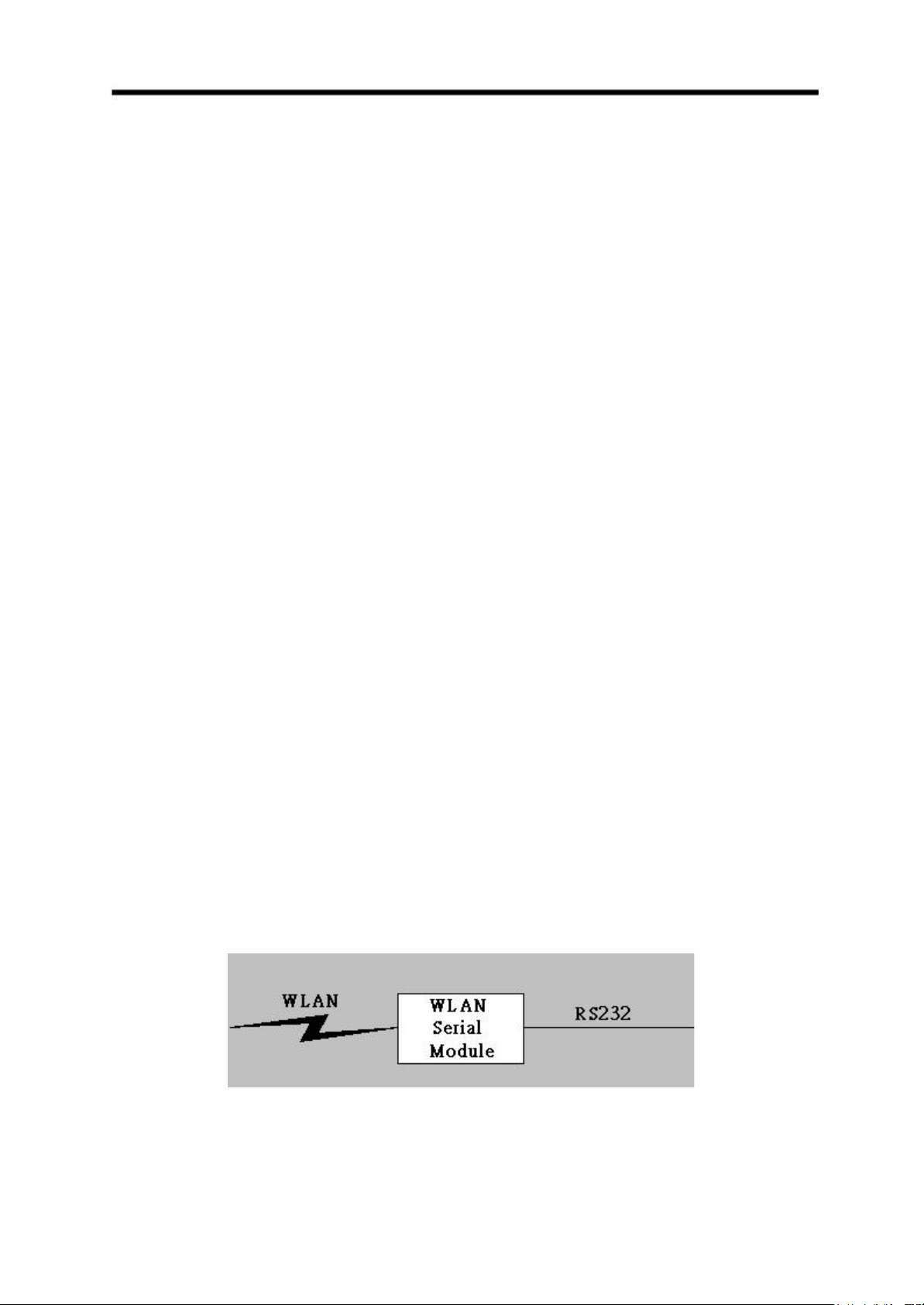
The Module provides the RS232 to WLAN converting function (Figure 1-1. For the device
(especially the device) that needs to replace the RS232 cable with WLAN, The
Module is the right choice.
Figure 1-1 RS232 to WLAN conversion
Page 10
S103 WLAN Compact Serial Module Version 1.0
9
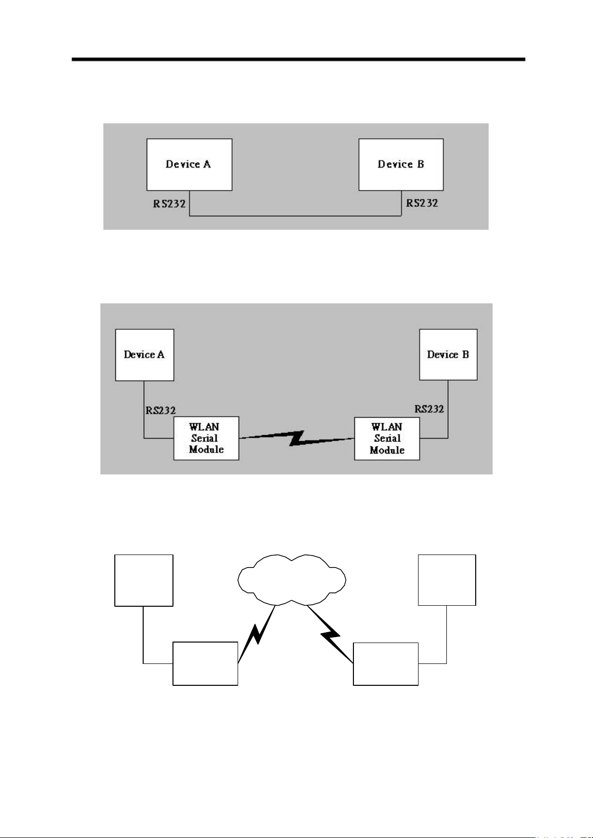
The following figure (Figure 1-2) shows the traditional RS232 connection.
Figure 1-2 Tradition RS232 Connection
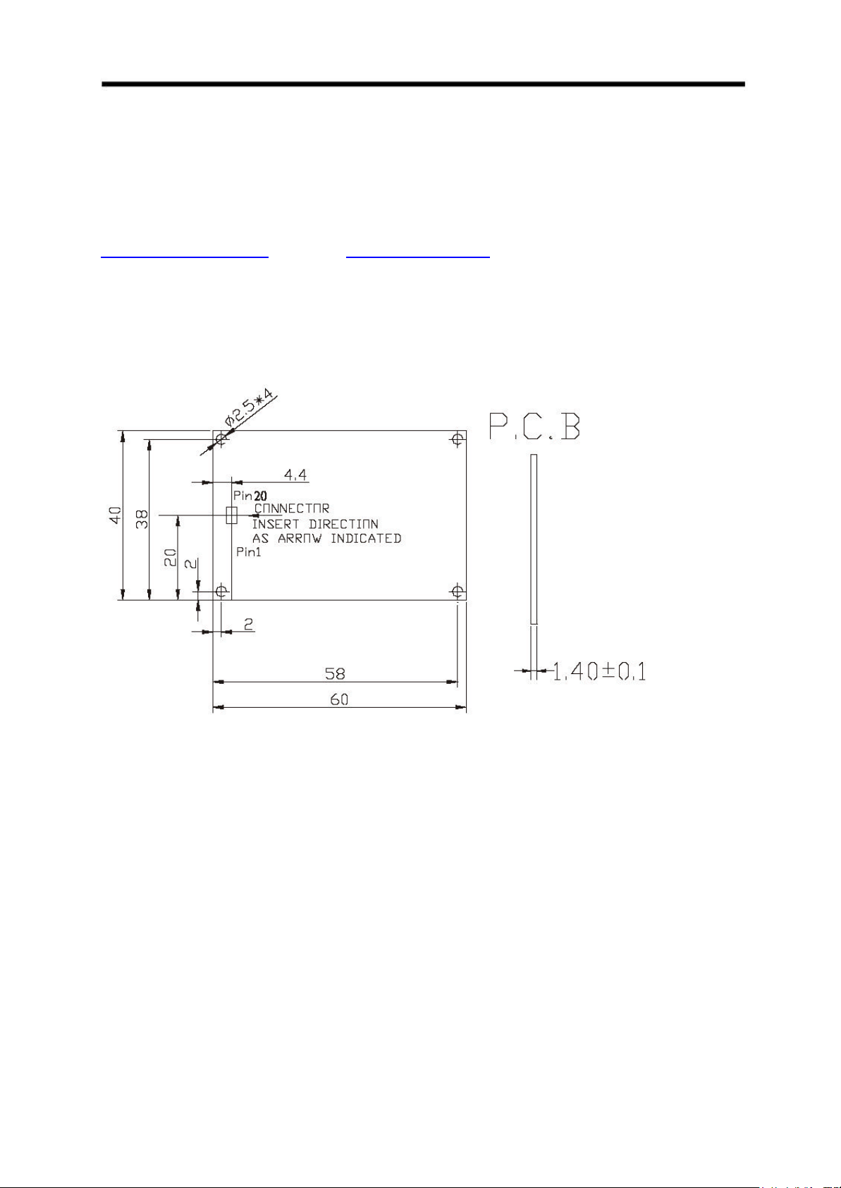
Few typical RS232 replacement (with WLAN) examples are shown in Figure 1-3 to Figure 1-6.
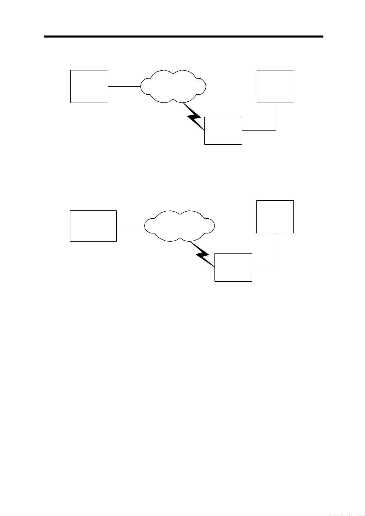
Figure 1-3 WLAN Pear to Pear connection
Device A Device B
RS232
WLAN
Serial
Module
Network
with AP
RS232
WLAN
Serial
Module
Figure 1-4 Two WLAN connections via AP
Page 11
S103 WLAN Compact Serial Module Version 1.0
10
Ethernet
Device A Device B
Network
with AP
RS232
WLAN
Serial
Module
Figure 1-5 One WLAN connection via AP
Windows PC
(Virtual COM)
Ethernet
Network
with AP
Device B
WLAN
RS232
Serial
Module
Figure 1-6 One WLAN connection via AP and Virtual COM
Page 12
S103 WLAN Compact Serial Module Version 1.0
11
**Statement:
The radio portion of this module has not been shielded. The module will be installed in
the OEM device only. OEM integrator should apply FCC certification after the module
installed to OEM device for meet FCC rules.
2. Installation
2.1 Package Contents
The Module is packed into the shipment box with partitioned multi-compartment.
The user manual, auto search and virtual COM utilities can be downloaded from
2.2 Module Dimension
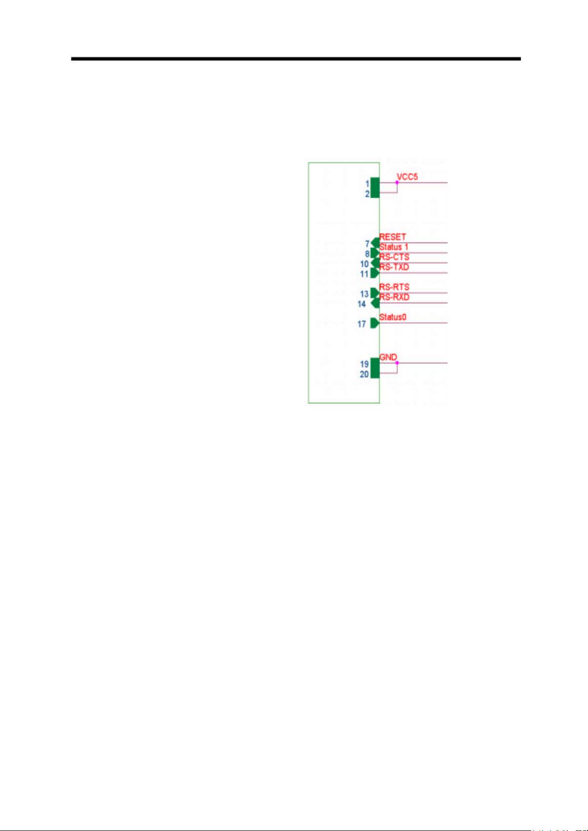
The size of The Module is shown below (Figure 2-1). [L: 60mm, W: 40 mm, H: 6 mm
(including the connector and component height)]
Figure 2-1 Module Dimension
The four small holes located at the four corners can be used to mount The Module into the
device main board.
Page 13
S103 WLAN Compact Serial Module Version 1.0
12
2.3 Pin-Out Definition
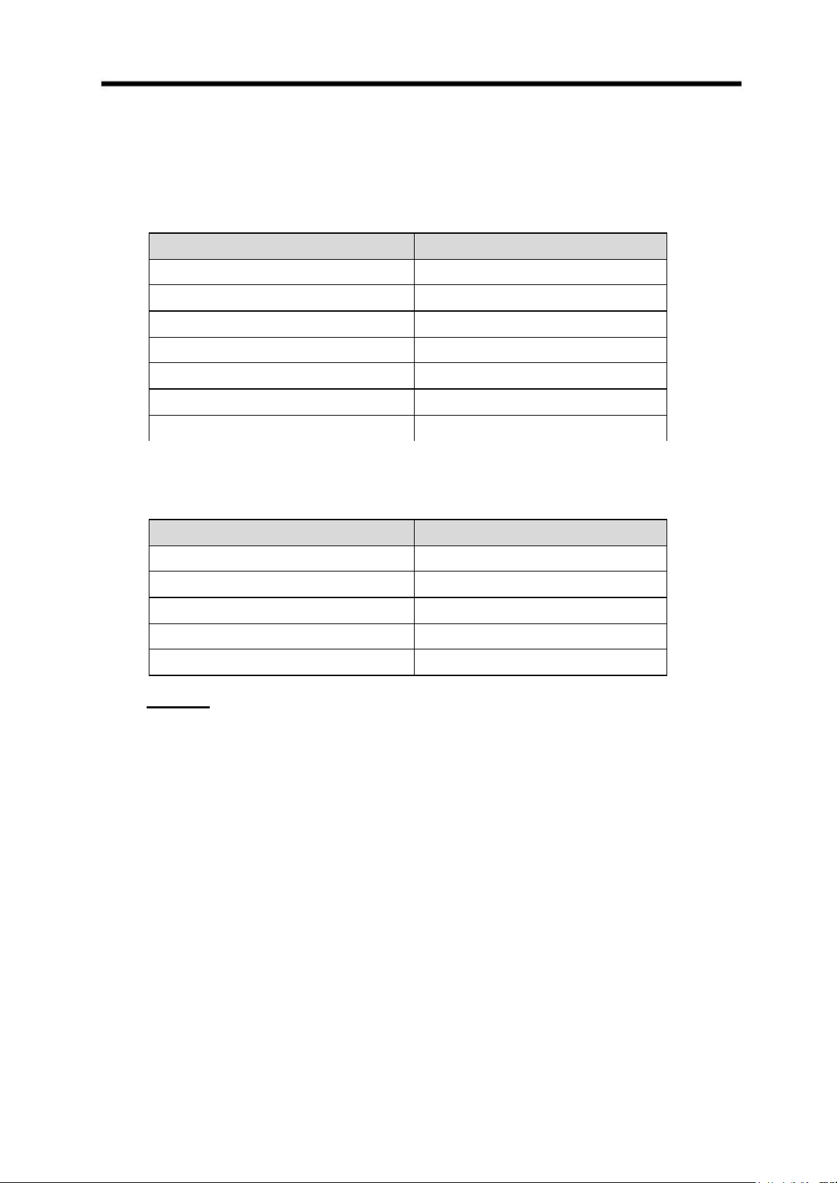
The Module supports 20-pin connector. The pin out definition for this connector is shown in
Figure 2-2
PIN 1&2=VCC5
PIN 7 = RESET (input)
PIN 8 = Status1 (output)
PIN 10 = RS -CTS (input)
PIN 11 = RS -TXD (output)
PIN 13 = RS -RTS (output)
PIN 14 = RS -RXD (input)
PIN 17 = Status0 (output)
PIN 19&20 = GND
Figure 2-2 Pin Out Definition
Page 14
S103 WLAN Compact Serial Module Version 1.0
13
2.4 Default Settings
The WLAN and RS232 default settings are shown in Table 1 and Table 2.
Table 1 WLAN Default Settings
Items Default Setting
IP Address 192.168.1.250
IP Subnet Mask 255.255.255.0
Gateway IP Address 192.168.1.254
SSID wlandemo
RF channel 6
WEP Disabled
Authentication Type Auto
Table 2 RS232 Default Settings
Items Default Setting
Baud Rate 38400
(1)
Data Length 8 (fixed)
Parity None (fixed)
Stop Bit 1 (fixed)
Flow Control None
Note (1): Baud rate can be 115200, 57600, 38400, 9600 bps.
Page 15

S103 WLAN Compact Serial Module Version 1.0
14
Configuration – Web Browser
To configure The Module, there are two methods can be applied:
- Web Browser Configuration (This section)
- Command Mode Configuration (refer to section 3)
For Web Browser configuration, there are two methods to enter the web browser:
Ÿ Direct Web Browser
Open the web browser and enter http://192.168.1.250 in the browser’s address box.
192.168.1.250 is the default IP address (refer to 2.4).
Note:
You will need to configure the IP address of your computer to be within the same
subnet as The Module and AP have for the initial configuration (please refer to
Appendix A).
Ÿ Auto Search Utility
The Auto Search Utility provides the locator function that allows you to find the available
WLAN Serial Modules in the network. Follow the steps below to install the utility:
- Stored the supplied Auto Search Utility file into your PC. Double Click “setup.exe”
- Follow the InstallShield Wizard to install the utility .
- When the installation is completed, click “Start”, “Programs”, “Auto Search Switch”
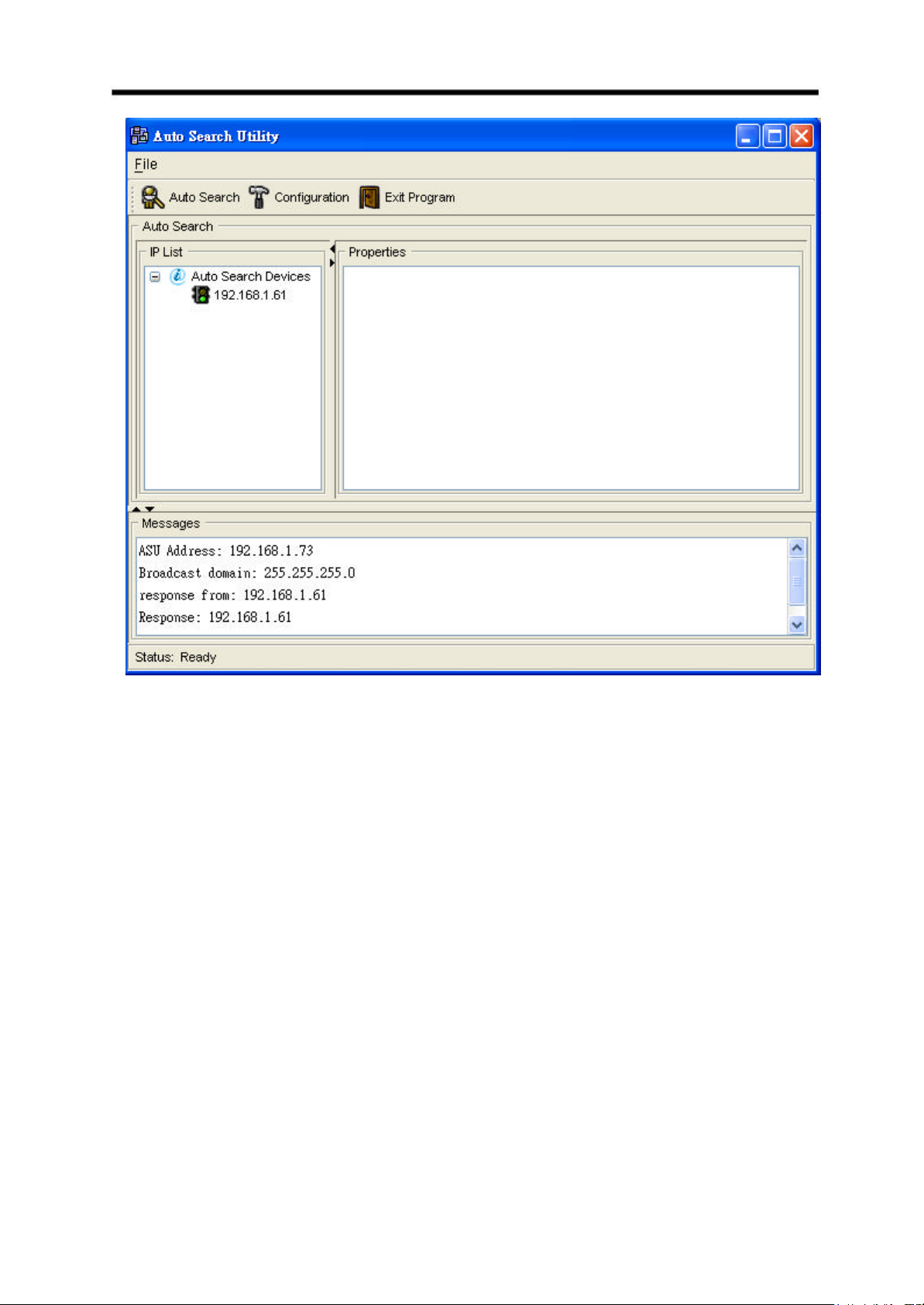
icon. The following window Figure 0-1 will be displayed:
- Click the Auto Search button at the top menu bar. When it finds The
Module, it will show the corresponding IP inside the IP list box. Double click the IP
address to enter the web browser for configuration. As shown in Figure 0-1, The
Module IP address is 192.168.1.61.
Page 16
S103 WLAN Compact Serial Module Version 1.0
15
Figure 0-1 Auto Search Utility
Page 17
S103 WLAN Compact Serial Module Version 1.0
16
2.5 Home Page
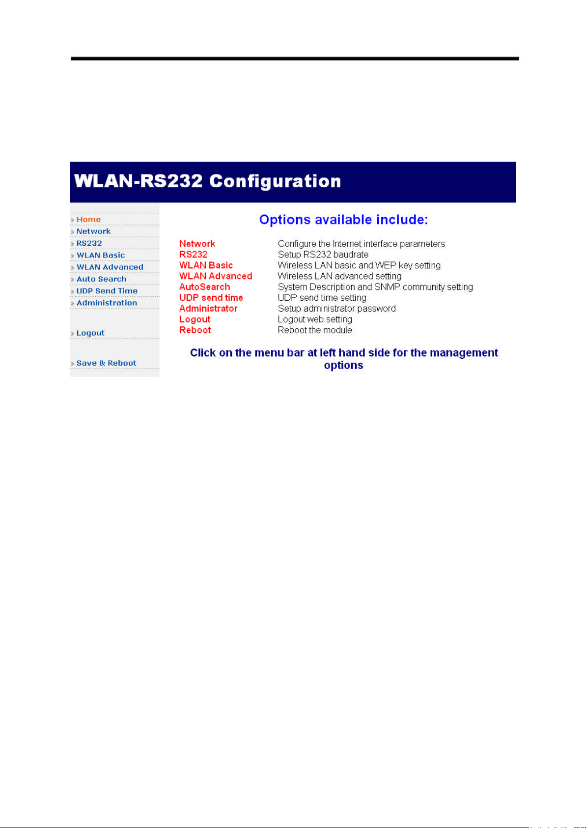
After login, the first page shown is the device Home page of The Module (See Figure 0-2). In
this page, it provides the brief description for each subsequent web page.
Figure 0-2 Home Page
Page 18
S103 WLAN Compact Serial Module Version 1.0
17
2.6 Administration
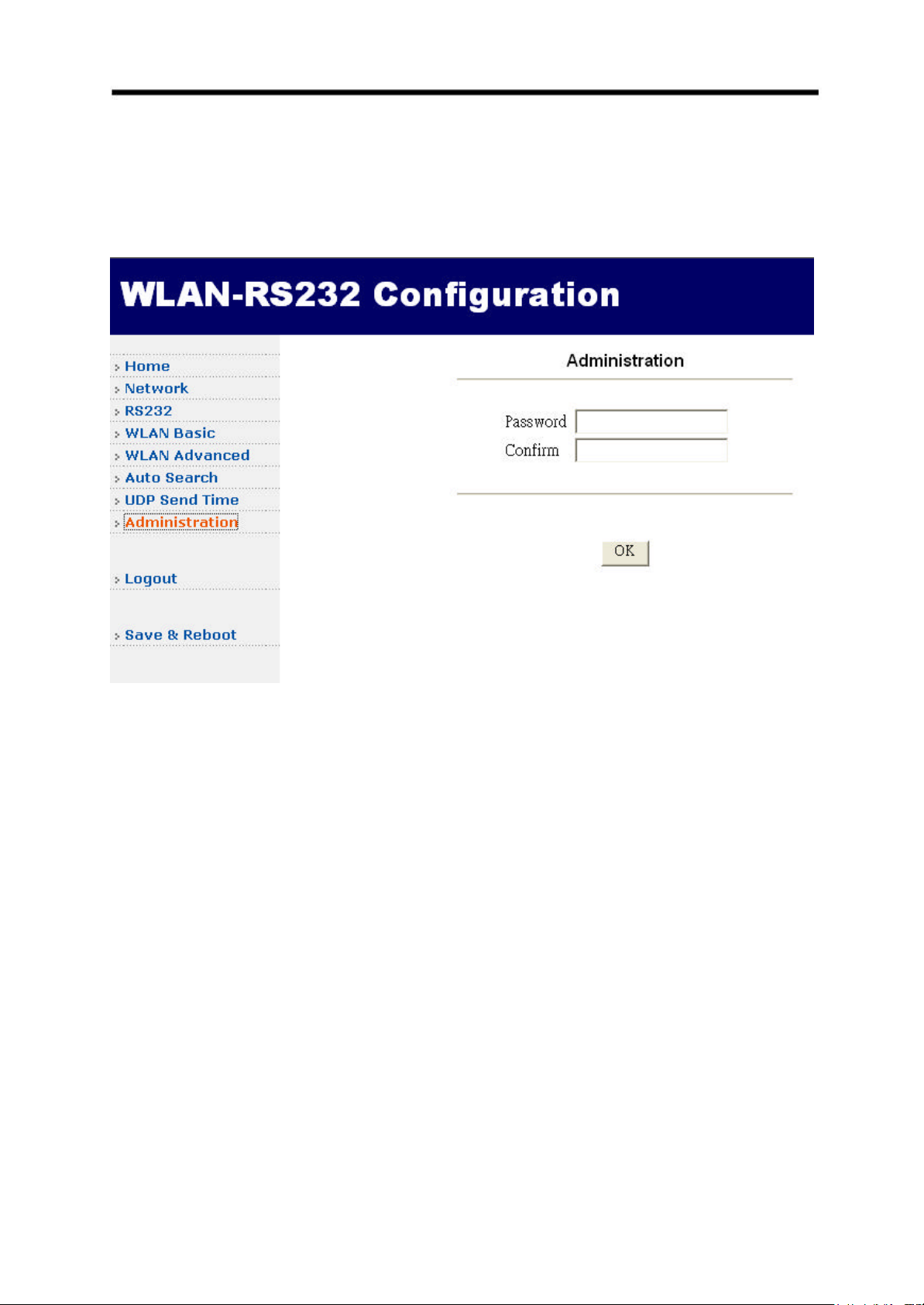
Click the Administration option on the left menu frame to change the password setting (See
Figure 0-3). By default, there is no password. So, it is strongly suggested to add the password
for the first time access.
Figure 0-3 Adm inistration
Page 19
S103 WLAN Compact Serial Module Version 1.0
18
2.7 Network
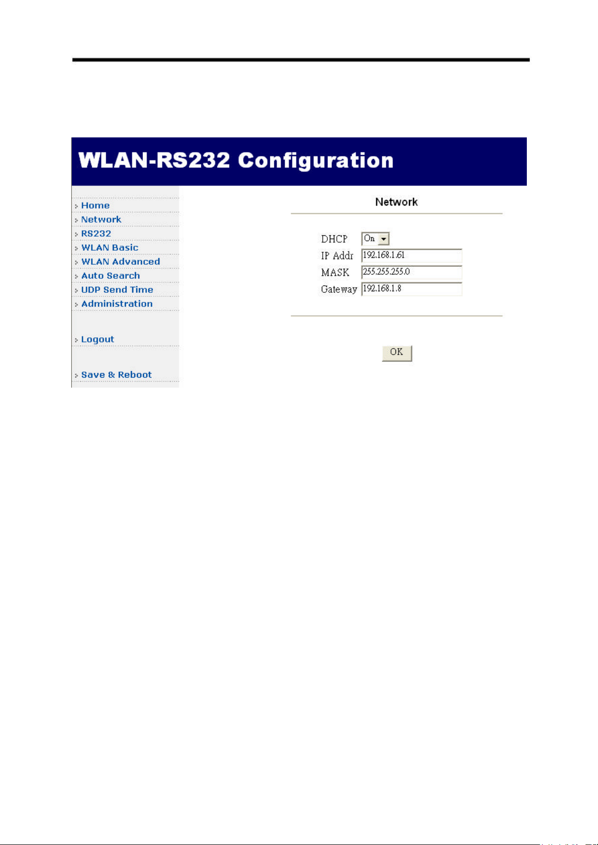
Click the Network option on the left menu frame to change The AP IP address settings (See
Figure 0-4
Figure 0-4 Network – IP address
There are two types of IP Address Mode – Static, DHCP client.
Static:
Enter the assigned IP address, subnet mask, gateway IP address and click OK.
DHCP:
DHCP client IP address mode means The Module will dynamically get its IP address and
other settings from DHCP server on the Ethernet network.
Page 20
S103 WLAN Compact Serial Module Version 1.0
19
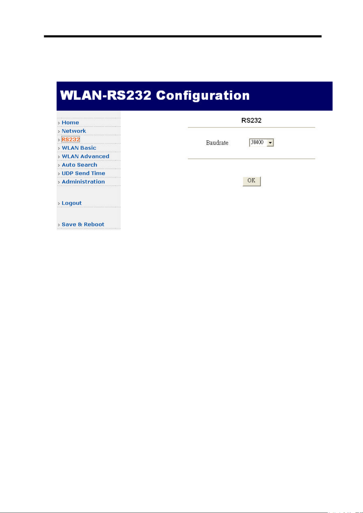
2.8 RS232
There are four RS232 baud rate can be selected from the RS232 web page (see Figure 0-5).
Figure 0-5 RS232
Page 21
S103 WLAN Compact Serial Module Version 1.0
20
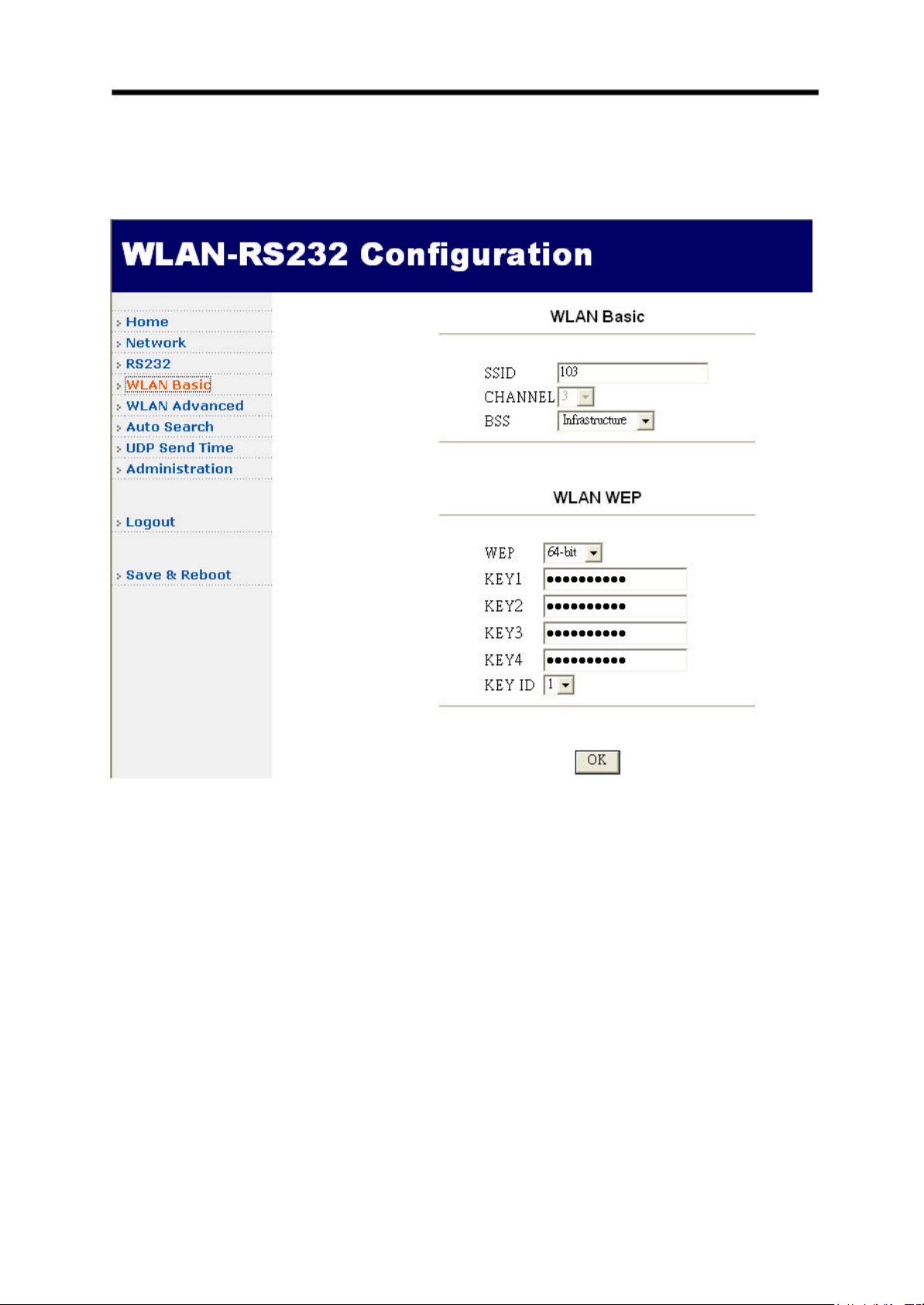
2.9 WLAN Basic
Click the WLAN Basic option on the left menu frame to change SSID, channel, operation
mode and WEP key (See Figure 0-6)
Figure 0-6 WLAN Basic
SSID (Service Set ID):
A unique ID shared by the same group Wireless Compact Serial Module and AP.
CHANNEL:
Radio channels used by The Module
BSS:
The Module can be operated in infrastructure mode or at AD-hoc mode.
WEP:
Enable/Disable the Wired Equivalent Privacy (WEP) mechanism based on the 64/128-bit
shared key to secure the wireless communication.
Page 22

S103 WLAN Compact Serial Module Version 1.0
21
WEP Key Length:
There are 2 WEP key lengths: 64-bit and 128-bit, encrypting transmitted data over the
wireless network securely. The larger WEP key length is, the higther level of security
becomes, but the lower throughput will be. You may disable (blank) to transmit data
without encryption.
Note:
Be sure that the WEP setting in The Module shall be the same as that in AP ,
otherwise the communication is impossible.
KEY# (1 ~ 4):
For 64-bit WEP encryption, a key of 10 hexadecimal characters in length must be filled in.
For 128-bit WEP encryption, a key of 26 hexadecimal characters in length must be filled
in.
Note:
Be sure that the key in The Module shall be the same as that in AP, otherwise the
communication is imp ossible..
Key ID:
Selects one of four key sets to be used for encryption.
Page 23
S103 WLAN Compact Serial Module Version 1.0
22
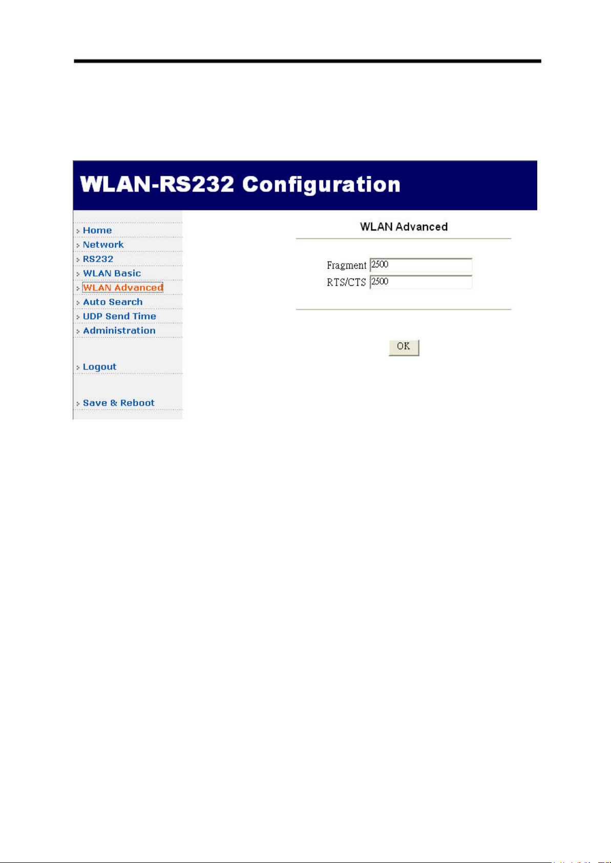
2.10 WLAN Advanced
Click the WLAN Advanced option on the left menu frame to set WLAN related parameters
(See Figure 0-7). You can change the values of The Module to have better interoperability
with AP.
Figure 0-7 WLAN Advanced
Fragment:
This value specifies the maximum size for a packet before data is fragmented into
multiple packets. It should remain at its default setting of 2500. Only minor reductions are
recommended.
RTS/CTS:
This value should remain at its default setting of 2500. Only minor reductions are
recommended.
Page 24
S103 WLAN Compact Serial Module Version 1.0
23
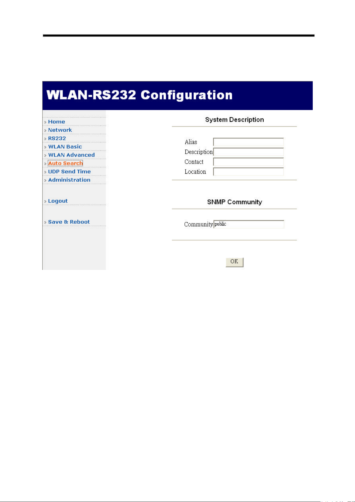
2.11 System Description for Auto Search
Click the Auto Search option on the left menu frame to enter the information about The
Module (See Figure 0-10).
Figure 0-8 System Description for Auto Search
Page 25
S103 WLAN Compact Serial Module Version 1.0
24
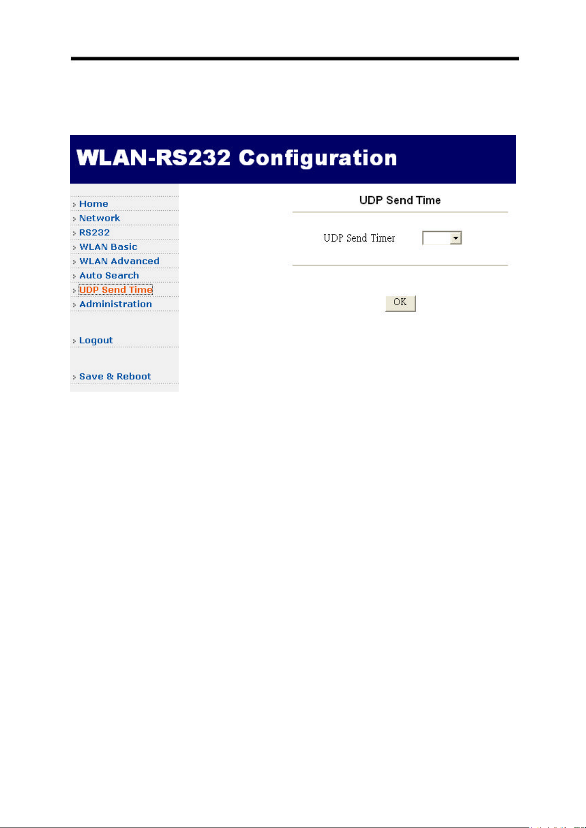
2.12 UDP Send Time
Click the UDP Send Time option on the left menu frame to adjust the UDP send time (See
Figure 0-9).
Figure 0-9 UDP Send Time
Page 26
S103 WLAN Compact Serial Module Version 1.0
25
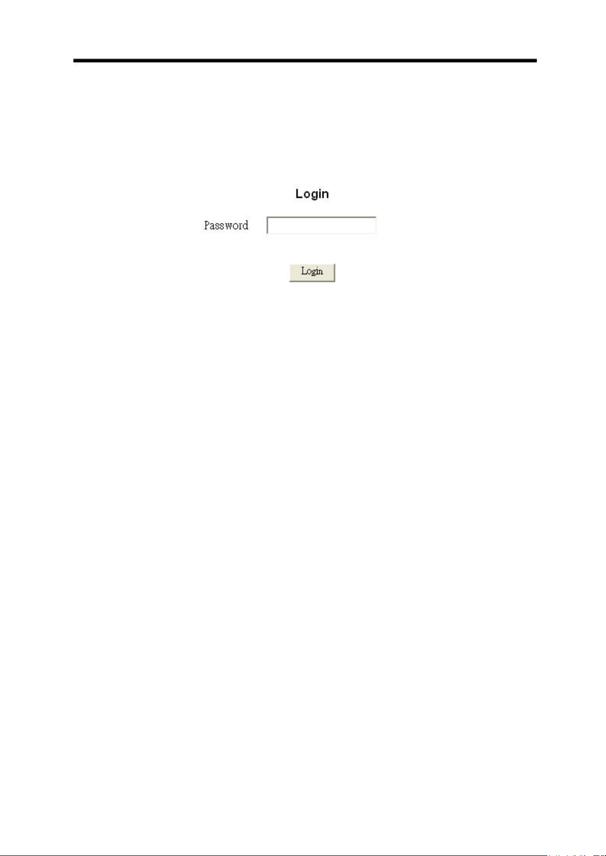
2.13 Logout
Click the Logout option on the left menu frame to logout the web page configuration. After the
logout, it will ask you to enter the password if you want to re-login again (See Figure 0-10).
Figure 0-10 Logout
2.14 Save & Reboot
Click the Save & Reboot option on the left menu frame to set save the new settings and
reboot it. (See Figure 0-2) Please wait until the reboot is completed.
Page 27
S103 WLAN Compact Serial Module Version 1.0
26
3. Configuration – Command Mode
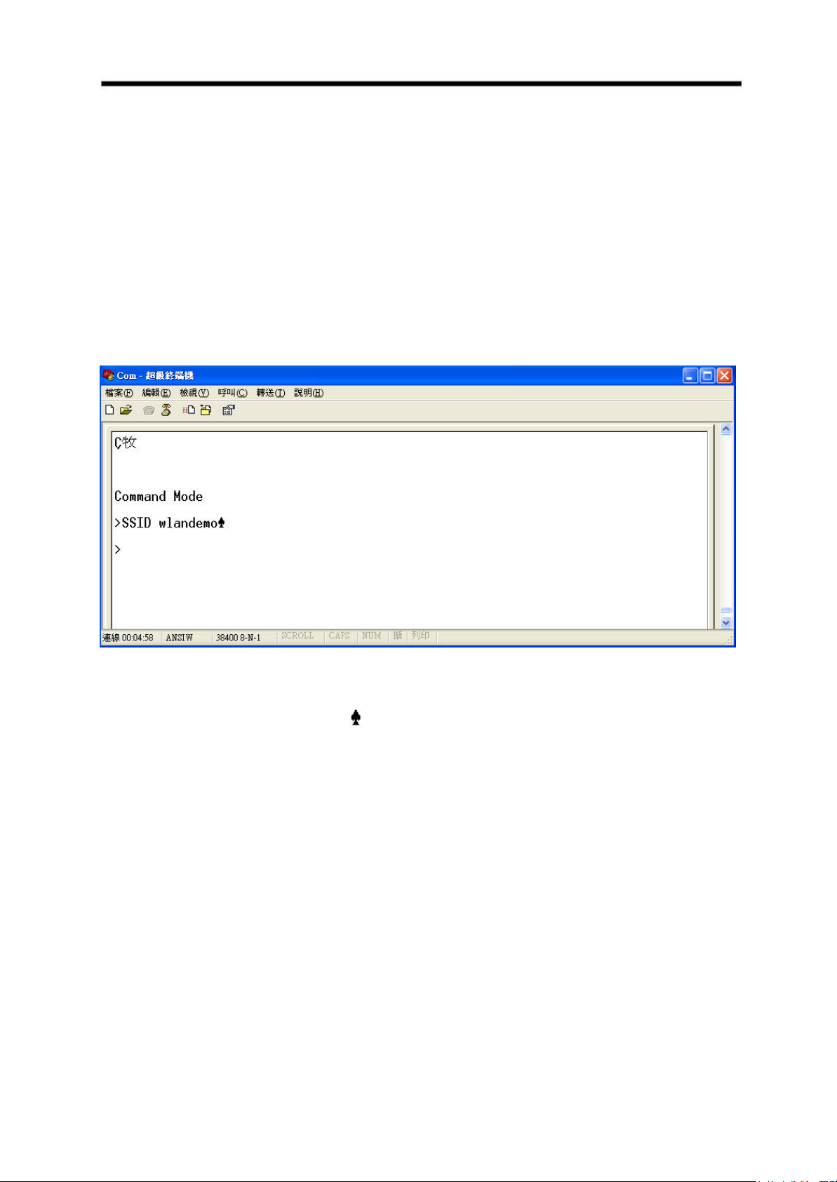
The Module can be configured via the command mode. The following are the steps to enter
the command mode:
1). Connect The Module to your PC with RS232 cable
2). Plug the power adapter to The Module
3). From your PC, open the Windows HyperTerminal application program and set the COM
port with the parameter as shown in section2.4
4). When the power is applied to The Module, press the “Backspace” key few times within 5
seconds. The following windows will be displayed:
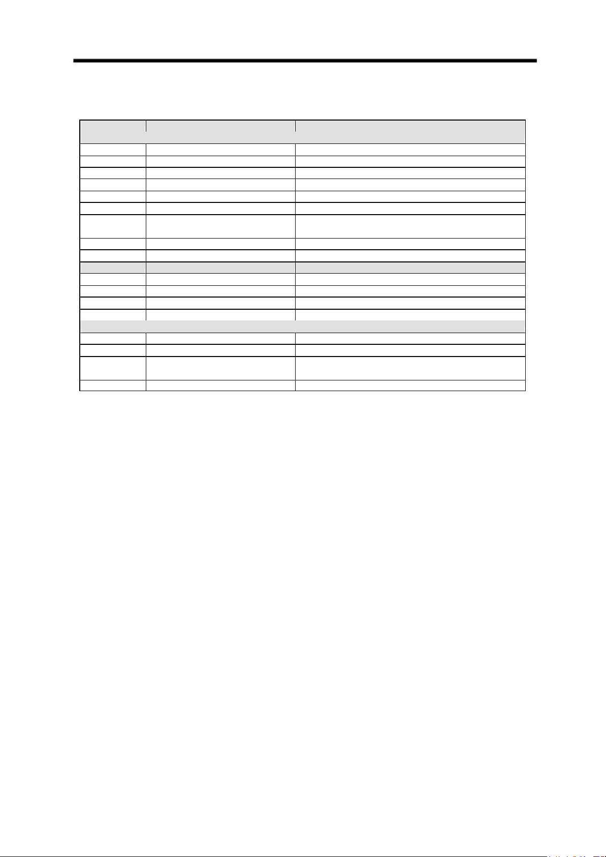
5). Enter the commands as shown in Table 3.
For example, enter “SSID wlandemo” to set the SSID value as “wlandemo”. The
Module will respond the symbol if the command is accepted.
Page 28
S103 WLAN Compact Serial Module Version 1.0
27
Set Authentication Algorithm
hout saving changed configuration
Table 3 Command List
Command Parameters Remark
For Wireless
MODE <[B]SS/[A]d-hoc/[P]seudoIBSS> Set network mode
SSID <SSID> Set SSID
CHAN <1-11> Set channel
PSMODE <1|0> Power saving mode ON/OFF
RATE <1/2/5/11> Set Tx rate
WEP <1|0> WEP ON/OF
AA <O|S|A>
OPEN/SHARE/AUTO
WK <1-4> <Key in Hex>
WKID <1-4> Set WEP Key ID
For Network
IP <IP address> Set IP
MASK <IP address> Set IP Mask
GW <IP address> Set Gateway IP
DHCP <1|0> Set DHCP client ON/OFF
For Operation
DEFAULT Restore to factory default settings
SAVE Save changed configuration parameters to flash
EXIT Exit wit
parameters
SE Save changed parameters and exit
Page 29

S103 WLAN Compact Serial Module Version 1.0
28
4. Troubleshooting
This section provides possible solutions to problems regarding the installation and operation
of The Module. Try to find answers here if there is any problem while you setup this device.
(1). Failed to configure The Module by using web browser via AP
- Check The Module WLAN parameter (like SSID) are the same as the AP.
- Check WEP-64 or WEP-128 is enabled or not. If it is on, the key must be the same.
- Ensure that your PC, AP and The Module are on the same network segment.
- Check Subnet Mask value, it should be 255.255.255.0.
(2). Lost or forgot Administrator password.
- Reset system by command.
- Re-configure The Module according to your previous setting.
Page 30
S103 WLAN Compact Serial Module Version 1.0
29
Appendix A Configure Your Computer IP manually
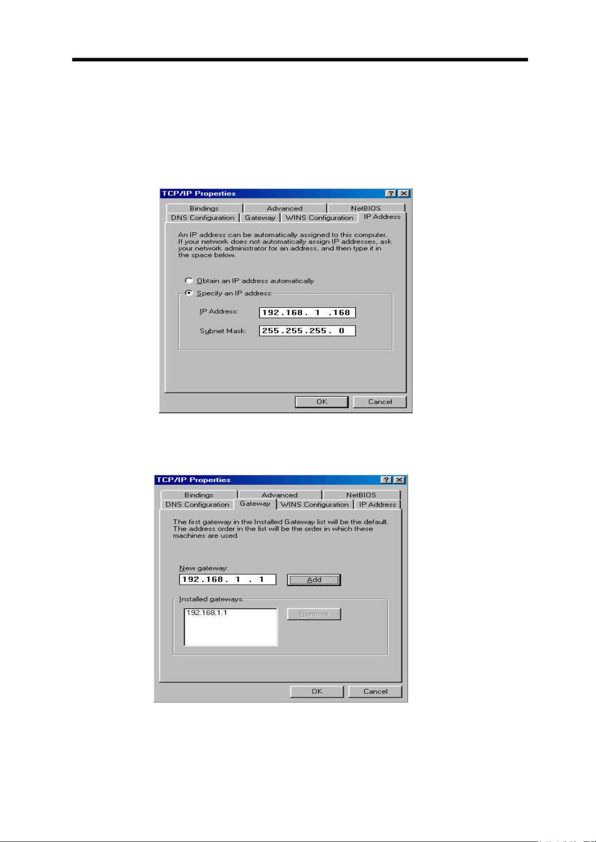
(a). Select IP Address tab, and then choose Specify an IP Address. Type in your
customized IP address (the default IP address of this product is 192.168.1.100. So you
just can type in one IP Address like 192.168.1.xxx.). Set the Subnet Mask as
255.255.255.0.
(b). Click Gateway tab, and add IP address of the router (e.g. the router’s IP Address is
192.168.1.1).
Page 31
S103 WLAN Compact Serial Module Version 1.0
30
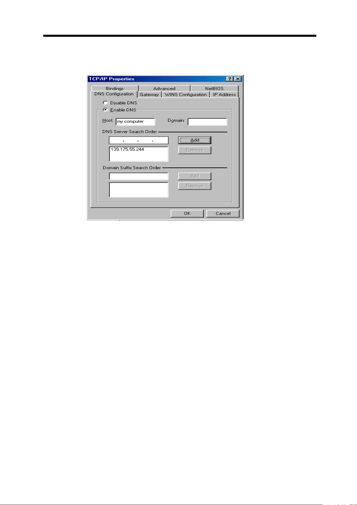
(c). Change to DNS Configuration tab; enable DNS and add DNS values provided by your
ISP into DNS Server Search Order.
(d). Click OK to finish.
Page 32

S103 WLAN Compact Serial Module Version 1.0
31
Appendix B Technical Information
Ÿ RS232 Features:
- Baud Rate Options: 115200, 57600, 38400, 9600 bps
- Data Length Options: 8 bits
- Parity options: None
- Stop Bits Options: 1 bit
- Flow Control: Hardware or none
- Serial USART Buffer: 256 bytes input, 256 bytes output
Ÿ WLAN Radio Features:
- Protocol Type: 802.11b standard compliant
- Operating Range:
Open Environment: 1000 ft./300m
Office Environme nt: 100-330 ft./30-100m
- Security:
WEP (Wired Equivalent Privacy) 64 and 128 bit encryption
Ÿ Radio Characteristics:
- Spread Spectrum Technology: DSSS
(Direct Sequence Spread Spectrum)
- RF Range: 2.4 ~ 2.4835 GHz
- Data Rate: 11 / 5.5 / 2 / 1 Mbps
- Modulation: DBPSK for 1 Mbps, DQPSK for 2 Mbps, CCK for 5.5 / 11 Mbps
- Operation Channels: US - 11, Europe - 13, France - 4, Spain - 2, Japan - 14
- RF Power Output (Typ.): 15±1 dBm
- Receive Sensitivity (Typ. @BER 10E-5): -83 dBm@11Mbps
Ÿ Power:
- Power Supply: 5 VDC Regulated
- Current: Tx 325mA, Rx 210mA, Power Down 80mA
Ÿ Software:
- Windows based Virtual Com Driver
- Utility: User setup and device -search software run on Windows98 /Me /NT /2000 /XP
Ÿ Mechanical:
- PCB or External Antenna
- Dimensions: 60 x 40 x 4.7 mm
Ÿ Environmental:
Page 33

S103 WLAN Compact Serial Module Version 1.0
32
- Temperature:
Operating: 0 to+55°C / 32 to 133℉
Storage: -20 to +65°C / -4 to +150℉
- Relative Humidity: 95% (non-condensing)
Ÿ EMC Certifications:
- U.S.A. FCC Part 15, Sections 15.247, 15.205, 15.209
 Loading...