

Page 1

Wireless LAN Access Point
User’s Manual
Version 1.1
Page 2

1
Copyright © 2003 by manufacturer. All rights reserved.
No part of this documentation may be reproduced in any form or by any means or used to
make any derivative work (such as translation, transformation, or adaptation) without
written permission from the copyright owner.
All the other trademarks and registered trademarks are the property of their respective
owners.
Statement of Conditions
The content described in this manual may be improved or changed at any time and it is
subject to be changed without notice.
Manufacturer assumes no responsibility for errors contained herein or for direct, indirect,
special, incidental or consequential damages with the furnishing, performance, or use of
this manual or equipment supplied with it, even if manufacturer of its suppliers have been
advised of the possibility of such damages.
Electronic Emission Notices
This device complies with Part 15 of the FCC Rules. Ope ration is subject to the following
two conditions:
(1) This device may not cause harmful interference.
(2) This device will accept any interference received, including interference that may
cause undesired operation.
FCC Radio Frequency Interference Statement
This equipment has been tested and found to comply with the limits for a class B digital
device, pursuant to Part 15 of the FCC rules. These limits are designed to provide
reasonable protection against harmful interference when the equipment is operated in a
commercial environment. This equipment generates, uses, and can radiate radio frequency
energy and, if not installed and used in accordance with the instruction manual, may cause
harmful interference to radio communications. Operation of this equipment in a
residential area is likely to cause harmful interference in which case the user need to
correct the interference at his area. If the equipment causes interference to radio or
television reception, try to correct the interference by using one or more of the following
measures:
Ÿ
Plug the equipment into an outlet that is on a different circuit from the television or
radio.
Ÿ Change the direction of the television or radio antenna until the interference
disappears.
Ÿ Move the equipment to one side or the other of the television or radio.
Ÿ Move the equipment farther away from the television or radio.
To assure continued compliance, any changes or modifications not expressly approved by
manufacturer could void the user’s authority to operate the equipment.
Page 3

2
FCC Radiation Exposure Statement
This device and its antennas must operate with a separation distance of at least 20 cm
from all persons and must not be co-located or operating in conjunction with any other
antenna or transmitter. End users must be provided with sp ecific operating instructions for
satisfying RF exposure compliance.
This product has been certified in France, Germany, Italy, Spain, Sweden, UK, and US.
Prohibition of co-location
This device and its antenna(s) must not be co-located or operating in conjunction with any
other antenna or transmitter.
Regulatory information / Disclaimers
Installation and use of this Wireless LAN device must be in strict accordance with the
instructions included in the user documentation provided with the product. Any changes
or modifications (including the antennas) made to this device that are not expressly
approved by manufacturer may void the user’s authority to operate the equipment. The
manufacturer is not responsible for any radio or television interference caused by
unauthorized modification of this device, or the substitution or attachment of connecting
cables and equipment other than manufacturer specified. It is the responsibility of the user
to correct any interference caused by such unauthorized modification, substitution or
attachment. Manufacturer and its authorized resellers or distributors will assume no
liability for any damage or violation of government regulations arising from failing to
comply with these guidelines.
Caution Statement of the FCC Radio Frequency Exposure
This Wireless LAN radio device has been evaluated under FCC Bulletin OET 65C and
found compliant to the requirements as set forth in CFR 47 Sections 2.1091, 2.1093, and
15.247(b)(4) addressing RF Exposure from radio frequency devices. The radiation output
power of this Wireless LAN device is far below the FCC radio frequency exposure limits.
Nevertheless, this device shall be used in such a manner that the potential for human
contact during normal operation —as a mobile or portable device but use in a body -worn
way is strictly prohibit. When using this device, a certain separation distance between
antenna and nearby persons has to be kept to ensure RF exposure compliance.
Page 4

3
MPE Statement (Safety Information)
Your device contains a low power transmitter. When device is transmitted it sends out
Radio Frequency (RF) signal.
LIMITED WARRANTY
This product is warranted by manufacturer to be free from defects in material and
workmanship for one (1) year from the date of purchase unless otherwise stated.
During this period if this product is found to be defective in material or workmanship,
manufacturer or one of its authorized service facilities will at its option either repair or
replace this product without charge, subject to the following conditions, limitations and
exclusions:
1. This warranty extends to the original consumer purchaser only and is not
assignable or transferable.
2. This warranty shall not apply to any product which has been subjected to misuse,
abuse, abnormal use, negligence, alteration or accident, or has had its serial
number altered or removed.
3. This warranty does not apply to any defects or damage directly or indirectly
caused by or resulting from the use of unauthorized replacement parts and/or
service performed by unauthorized personnel.
4. This warranty does not apply to the software driver that accompanies this product.
This warranty is made expressly in lieu of all other warranties, expressed or implied,
including but not limited to any implied warranty of merchantability of fitness for a
particular purpose, and all other obligations on the part of Manufacturer provided,
however, that if the disclaimer of implied warranties is ineffective under applicable law,
the duration of any implied warranties arising by operation of law shall be limited to one
(1) year from the date of purchase or such longer period as may be required by applicable
law.
Manufacturer hereby disclaims any and all liabilities for consequential and incidental
damages arising out of or in connection with any breach of this warranty or any other
claim with respect to this product, including but not limited to claims of negligence, strict
liability in tort or breach of contract.
Page 5

4
Table of Contents
1. INTRODUCTION...........................................................................................5
1.1 Features....................................................................................................5
1.2 Applications .............................................................................................5
2. INSTALLATION............................................................................................7
2.1 Product Kit ...............................................................................................7
2.2 System Minimum Requirements................................................................7
2.3 AP’s location ............................................................................................7
2.4 Plug in Power ...........................................................................................7
2.5 Connect to a Network ................................................................................8
2.6 Connect to an ADSL modem..................................................................... 9
2.7 Install Utilities........................................................................................ 10
2.8 Install AP’s Driver .................................................................................. 11
3. CONFIGURATION ...................................................................................... 13
3.1 AP Utility...............................................................................................14
3.2 SNMP Manager ......................................................................................15
3.3 RSS Tool ................................................................................................ 15
3.4 Web Management ...................................................................................16
4. CONFIGURE AP AS BRIDGE - BLEND MODE (POINT TO MULTIPOINT
MODE AND POINT TO POINT SETTINGS) ...............................................18
4.1 Block Diagram .......................................................................................18
4.2 Configuration via SNMP manager...........................................................18
4.2.1 Open Access Point SNMP Manager window.............................. 18
4.2.2 Configuration procedure for bridge – blend mode .......................20
4.2.3 Wireless Repeater Mode............................................................ 26
4.3 Adjust the best angle of antenna .............................................................. 31
5. SPECIFICATIONS .......................................................................................33
6. GLOSSARY.................................................................................................35
7. DEFAULT SETTINGS .................................................................................37
8. WIRELESS LAN SYSTEM ..........................................................................41
8.1 802.11 Ad -Hoc Configuration ................................................................. 41
8.2 Infrastructure Configuration ....................................................................41
9. DISABLE IP FILTERING.............................................................................44
Page 6

5
1. INTRODUCTION
Wireless LAN is local area networking without wires, which uses radio frequencies to
transmit and receive data between PCs or other network devices. Wireless LAN is able to
configure independent networks and infrastructure networks. The former is suitable for
small or temporary peer-to-peer configurations, and the latter is offering fully distributed
data connectivity via micro cells and roaming.
The Wireless Access Point (AP) is designed to meet the mobility, performance, security,
interoperability, management, reliability requirements of IEEE 802.11b high data rate
standard and IEEE 802.3 Ethernet 10 Base-T standard. This installed AP can
communicate with other IEEE 802.11b and IEEE 802.3 compatible products to create a
wireless network in your office or home.
1.1 Features
• Compliant with IEEE 802.11b standard
• Automatic data rate fallback under noisy environment (11 / 5.5 / 2 / 1 Mbps)
• Supports full mobility and seamless roaming from cell to cell
• Local, remote and automatic configuration
• Easy client management with supplied utility software
• Desktop and wall/ceiling mount
• Operating range
- Open environment: Up to 300m
- Office environment: 30 ~ 100m
• Bridging function
• Support IEEE 802.11d International roaming
• Provide repeater function
• Wireless to wireless filtering
• Site Survey function
• Support IEEE 802.1x Port Based Network Access
• Provide web server function
1.2 Applications
• Home networking for device sharing - Remote access to corporate network
information email, file transfer and terminal emulation.
• Frequently changing environments - Retailers, manufacturers and banks that
frequently rearrange the workplace and change location.
•
SOHO (Small Office and Home Office) users - SOHO users need easy and quick
installation of a small computer network functions.
• Inter-building connection - The wireless building-to-building network installs
quickly, requires no monthly lease fees, and provides the flexibility to
reconfigure easily.
• Typical applications include hard -to-wire buildings, campuses, hospitals/medical
offices, warehouse, security huts, exhibition centers, etc.
• Temporary LANs for special projects or occasions - Auditors require workgroups
Page 7

6
at customer sites. Trade shows, exhibitions, retailers, airline, and shipping
companies need additional workstations for the peak periods of data traffic.
Page 8

7
2. INSTALLATION
Please follow steps described in Section 2.1 through 2.8 to install your AP -- including
hardware, driver, and utilities.
2.1 Product Kit
Before starting installation, please make sure the Wireless Access Point (AP) package you
purchased includes the following four items:
1) Wireless Access Point with one antenna.
2) CD-ROM (containing Driver/Utility, and User’s Manual).
3) User’s Manual (hard copy).
4) Power adapter with power cord.
If anything from the above items is missing, please contact your vendor.
2.2 System Minimum Requiremen ts
Your system should meet the following minimum requirements to install the AP
successfully.
1) LAN with Ethernet network device such as hub or switch.
2) An A/C power outlet (100~240V, 50~60Hz) close to the location of AP (refer
to Section 2.3).
3) UTP Ethernet cable (category 3, 4, or 5) with RJ-45 connectors and enough
length from the location of AP to the hub.
2.3 AP’s location
Please choose a proper place for your AP. Normally, the best location to place the AP is at
the center of all your mobile stations within line of sight. The higher altitude is for the
AP’s location , the better performance it may have.
2.4 Plug in Power
Plug the power cord of power adapter into the socket marked with on the rear panel
of AP, and plug the power adapter into an A/C power outlet. When completed, the power
LED on the top panel should light up as shown in Table 1. Note that only use the power
adapter supplied with AP; otherwise, the AP may be damaged.
Page 9

8
Table 1. LED Indicators
LED Off On Flash
LAN
No power.
No network
connection.
Link to hub, but no
network traffic .
LAN traffic is detected. The
heavier the traffic, the faster
the LED flashes.
Nil. Nil. RSS is detected. The bigger
RSS
the RSS, the faster the LED
flashes.
No power. Power on Nil.
Power
Nil. Nil. Radio traffic is detected. The
WLAN
heavier the traffic, the faster
the LED flashes.
2.5 Connect to a Network
Plug one end of a RJ -45 UTP Ethernet cable into the socket marked with on the rear
panel of AP, then plug the other end of this Ethernet cable into a free socket of the hub’s
LAN ports. When completed, the LAN LED on the top panel should light up as shown in
Table 1.
Note that your wireless LAN is able to operate in some simple systems, i.e. only one AP
and a DHCP server available, by using the default settings (refer to Section 7) whenever
you have completed the above steps successfully . If in such case, your installation process
is completed and you can neglect the following steps. Otherwise, the following steps
should be resumed for complicated systems or for the case that you would like to change
the AP’s settings.
Page 10
9
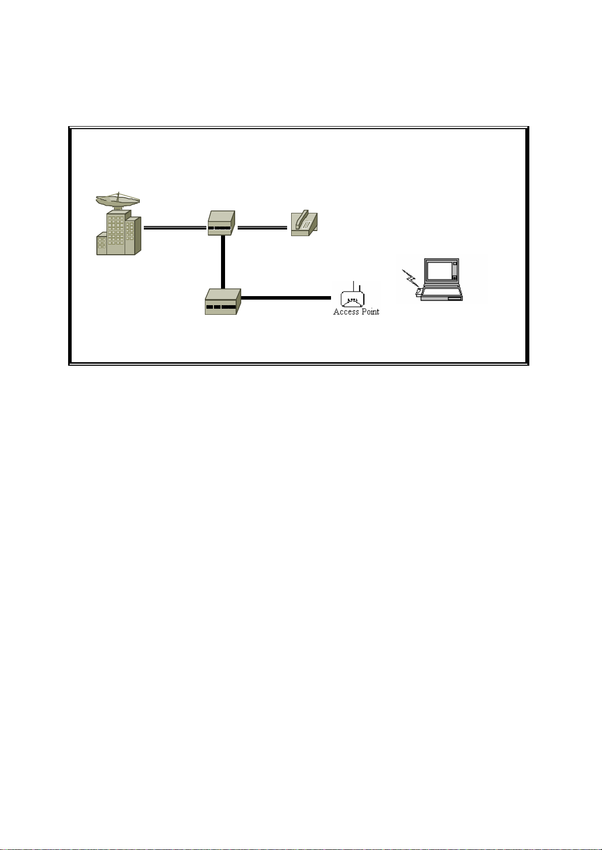
2.6 Connect to an ADSL modem
Phone line
Notebook with
PSTN
ADSL splitter
Phone line
Phone
ADSL MODEM
(ATU-R)
Ethernet Cable
Wireless LAN Card,
Wireless USB Dongle
Direct Connection of AP to ADSL Modem
Please note the conditions for the connection of AP with ADSL modem:
If the AP is directly connected to the ADSL modem output, an Ethernet cable type
(crossover or straight -through) is dependent on ADSL modem.
If the AP is connected to the ADSL modem through a hub, it depends on what kinds of
ADSL services.
1) ADSL service with dynamic IP addresses: the AP is connected to one of the
hub’s LAN ports, standard RJ -45 cables are used to connect among AP, Hub,
and ADSL modem.
2) ADSL service with a fixed IP address: A Router or IP sharing device is
included so that the AP and other devices connected to the hub’s LAN ports
can share the same IP address for operations.
Disabling IP filtering function is needed for the AP configuration, the normal settings of
ADSL modem, Access Point, and WLAN NIC can then be followed for installations.
See section 9 that shows how to disable the IP filtering of AP.
Page 11
10
2.7 Install Utilities
Before installing the utilities into your PC, you have to ensure that your PC is running
under Win dows 98, Me, NT, 2000, or XP operating system and has minimum 5 Mbytes
free disk space.
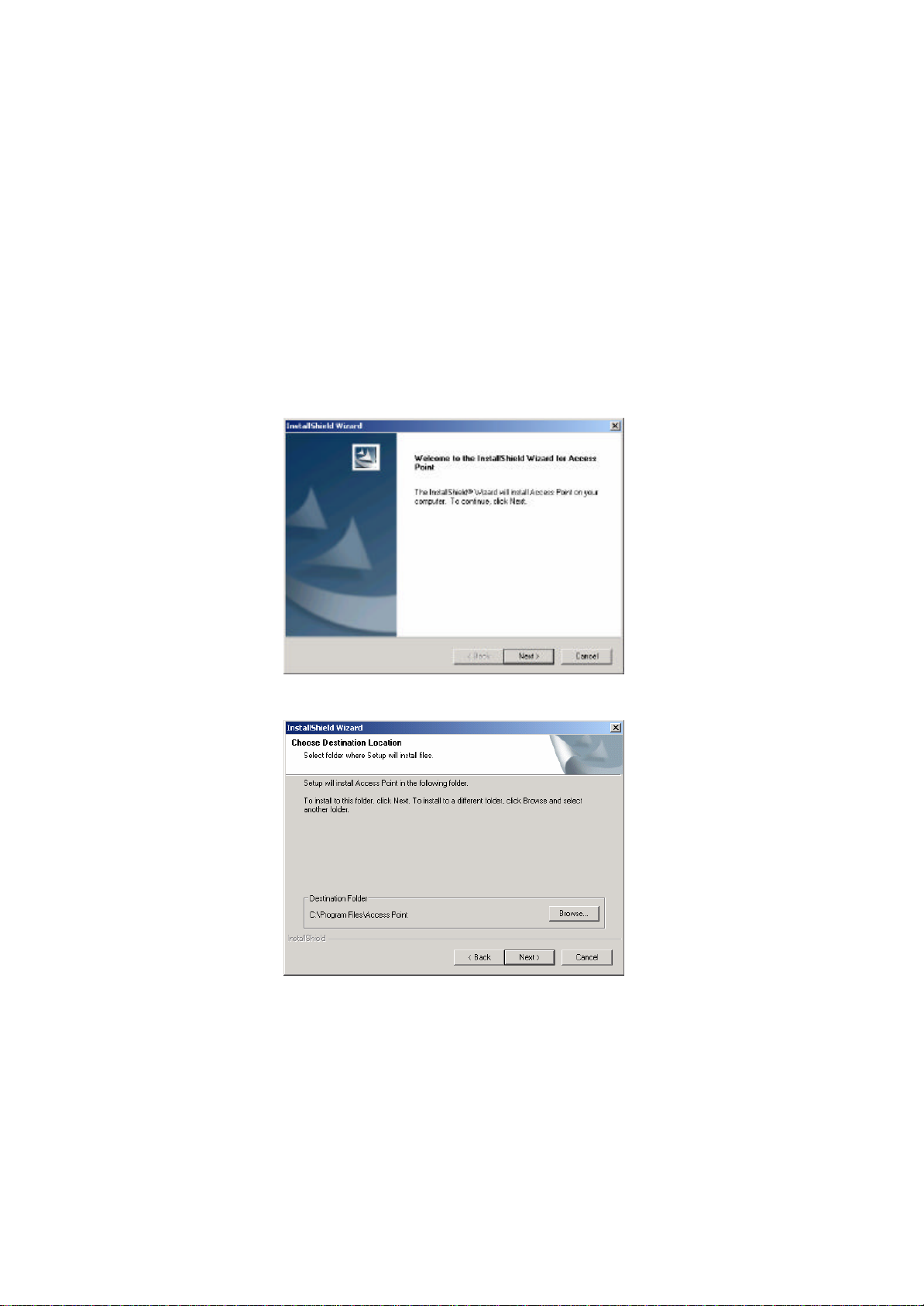
Please follow the steps below to install three utilities, AP Utility, SNMP Manager and
RSSTool . The first is used for the local configuration, the second is the remote
configuration, and the last is the RSS test tool. The first two utilities perform the same
functions except the password options and physical connections.
1) Insert the supplied CD-ROM in the CD-ROM drive.
2) Run \Utilities\setup.exe in the CD-ROM.
Page 12
11
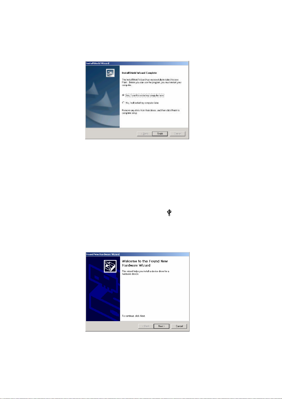
3) Follow the prompted instructions to finish the installation.
4) Restart your PC when prompted.
2.8 Install AP ’s Driver
You may skip the AP’s driver installation on the conditions that:
1) Your PC cannot connect to AP through an USB cable.
2) Your PC is running Windows 95 or NT where USB connection is not
supported.
3) The local configuration is needed.
Please follow the steps below to install the AP ’s driver.
1) Plug an USB cable into socket marked with on the rear panel of AP, and
plug the other end of the USB cable into USB port (type A) of the PC.
2) When plugged, your PC should detect the inserted AP automatically and
display New Hardware Found on the display box.
Page 13
12
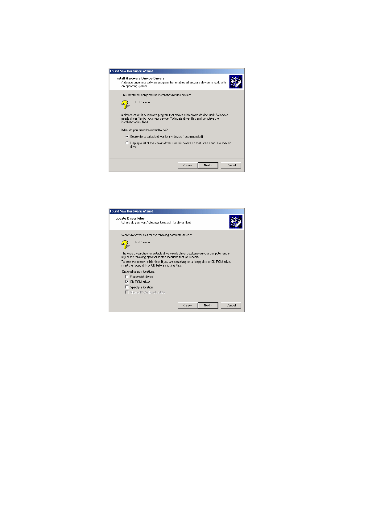
3) Put the supplied CD-ROM in the CD-ROM drive.
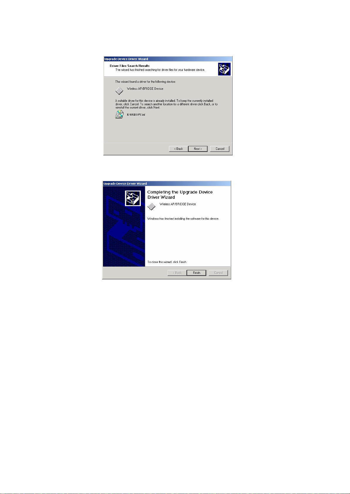
4) The driver installation procedure will guide you through the standard steps
from your operating system.
Page 14
13
5) Restart your PC when prompted.
3. CONFIGURATION
After you have completed the Installation process of Section 2 successfully, please follow
this section to configure the settings of AP in order to fit in your environment. There are
three utilities available, AP Utility、 SNMP Manager and RSSTool. The first is used for
local configuration, the second is used for remote configuration, and the last is the RSS
test tool. They are described in Sections 3.1 、3.2 and 3.3 respectively. You can also
configure the settings of AP by Web Management, it is described in Sections 3.3.
The following notations for configurations will be used in this manual.
The window names will be printed in italic fonts.
The items that need actions or inputs within the window will be printed in bold fonts.
Page 15
14
3.1 AP Utility
Before running AP Utility, you have to make sure that:
1) Your PC is connected to the AP properly through an USB cable.
2) Your PC is running under Windows 98, Me, 2000, or XP.
3) AP Utility has been installed (refer to Section 2.7).
4) The AP’s driver has been installed (refer to Section 2.8).
5) The AP is turned on.
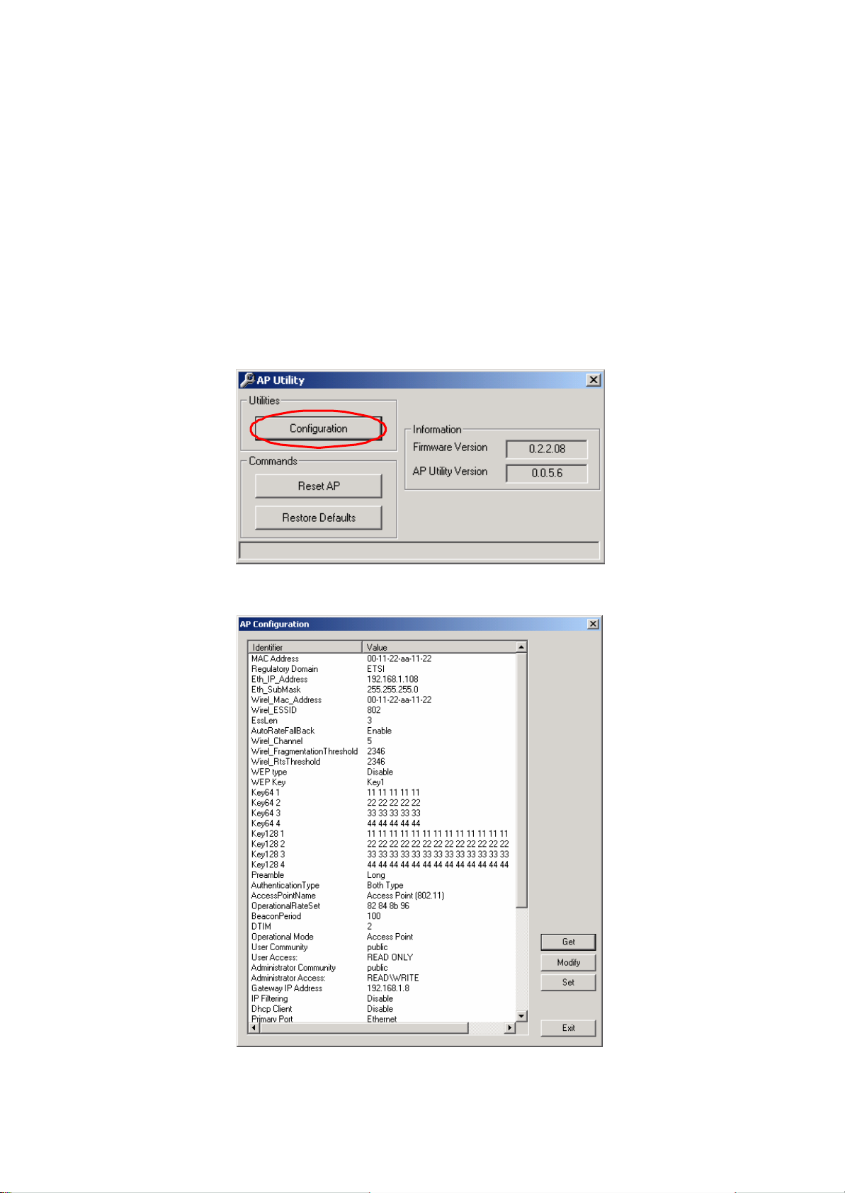
Run the AP Utility from Start, Program, Access Point Utilities, and AP Utility. A window
AP Utility Application will be displayed. Three buttons allow you to do the following
functions.
1) Configuration: Configure the settings of the AP.
Page 16
15
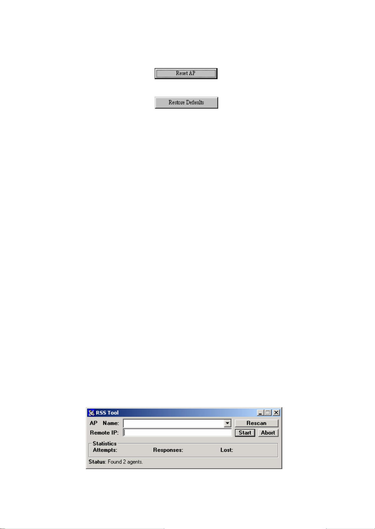
2) Reset AP: Reset the AP and new configuration will take effect.
3) Restore Default: Restore the factory default values (refer to Section 6).
After you click the Configuration button, a window AP Configuration with the current
settings will be displayed. Click the Get button to receive the settings in configuration
window . Click the listed identifier and press the Modify button, a popped-up window
allows you to input the new setting. The new settings will be stored to the AP only after
you click the Set button. Click the Exit button when completed. Please refer to Section 7
for the detailed information of each setting.
3.2 SNMP Manager
Before running SNMP Manager, you have to make sure that:
1) The AP is turned on and is connected to a LAN.
2) Your PC can access to the AP.
3) Your PC is running under Windows 98, Me, 2000, XP, or NT.
4) SNMP Manager has been installed (refer to Section 2.7).
Run the SNMP Manager from Start, Program, Access Point Utilities, and SNMP Manager .
A window Access Point SNMP Manager will be displayed. If you have difficulty in using
it, please run from Start, Program, AP, and SNMP Help for the detailed description about
how to operate the SNMP Manager.
3.3 RSS Tool
Before running RSSTool , you have to make sure that:
1) The AP is turned on and is connected to a LAN.
2) Your AP’s operational mode is bridge mode.
3) Your PC can access to the AP.
4) Your PC is running under Windows 98, Me, 2000, XP, or NT.
5) RSSTool has been installed (refer to Section 2.7).
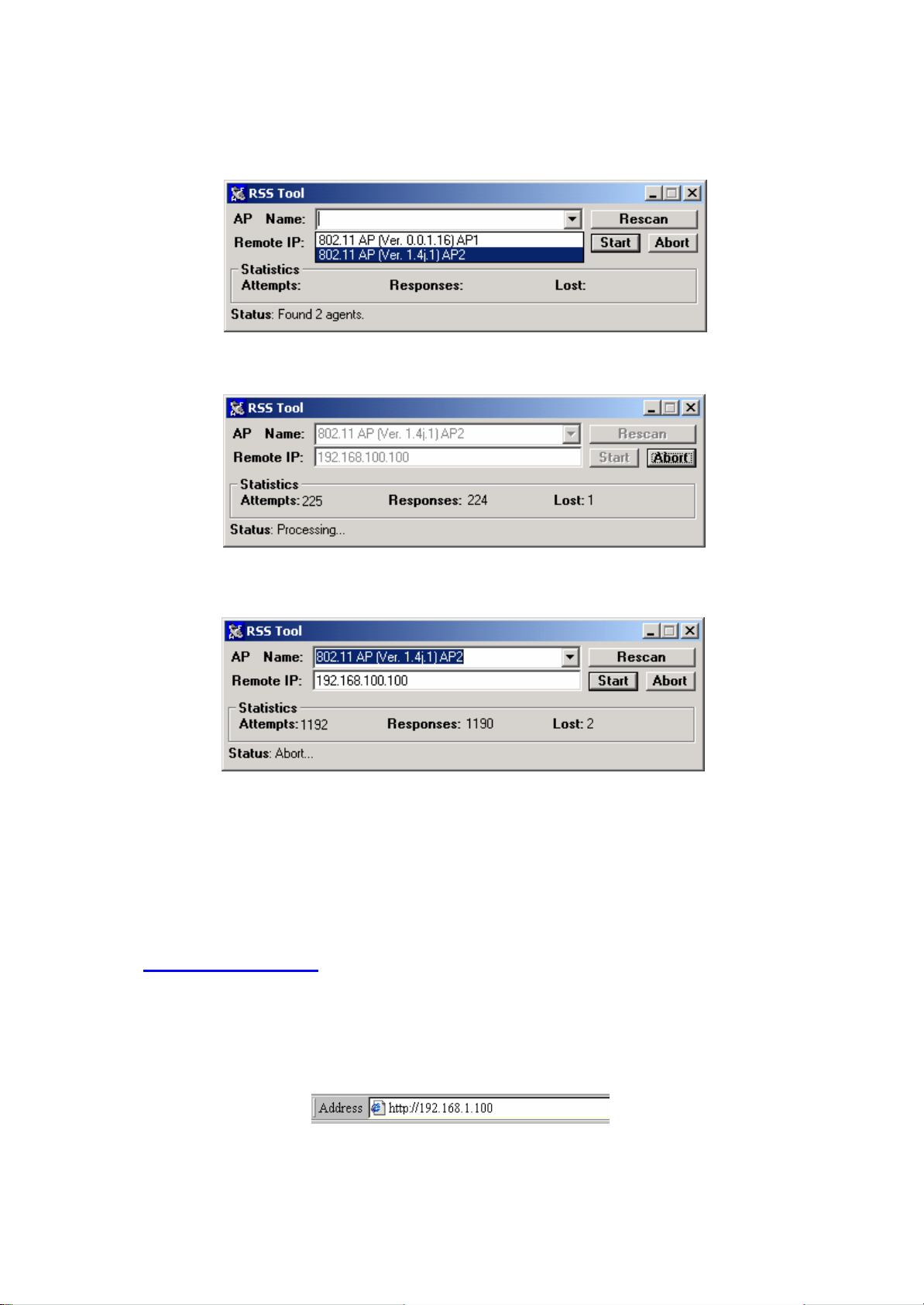
Run the RSSTool from Start, Program, Access Point Utilities, and RSSTool. A window
RSSTool Application will be displayed. Three buttons allow you to do the following
functions.
Page 17
16
1) Rescan: Rescan the AP on the same subnetwork.
2) Start: Start send message to remote AP.
3) Abort: Stop send message to remote AP.
Note: When RSSTool is running, you can’t run SNMP Manager at the same time.
3.4 Web Management
The built -in Web Management provides you with a set of user-friendly graphical user
interfaces (web pages) to manager your Access Points. With the assigned IP address
(e.g. http://192.168.1.100/, 192.168.1.100 is the default IP address) to the Access
Point, you may get access to the Access Point Web Pages via a web browser to
monitor and configure the Access Point.
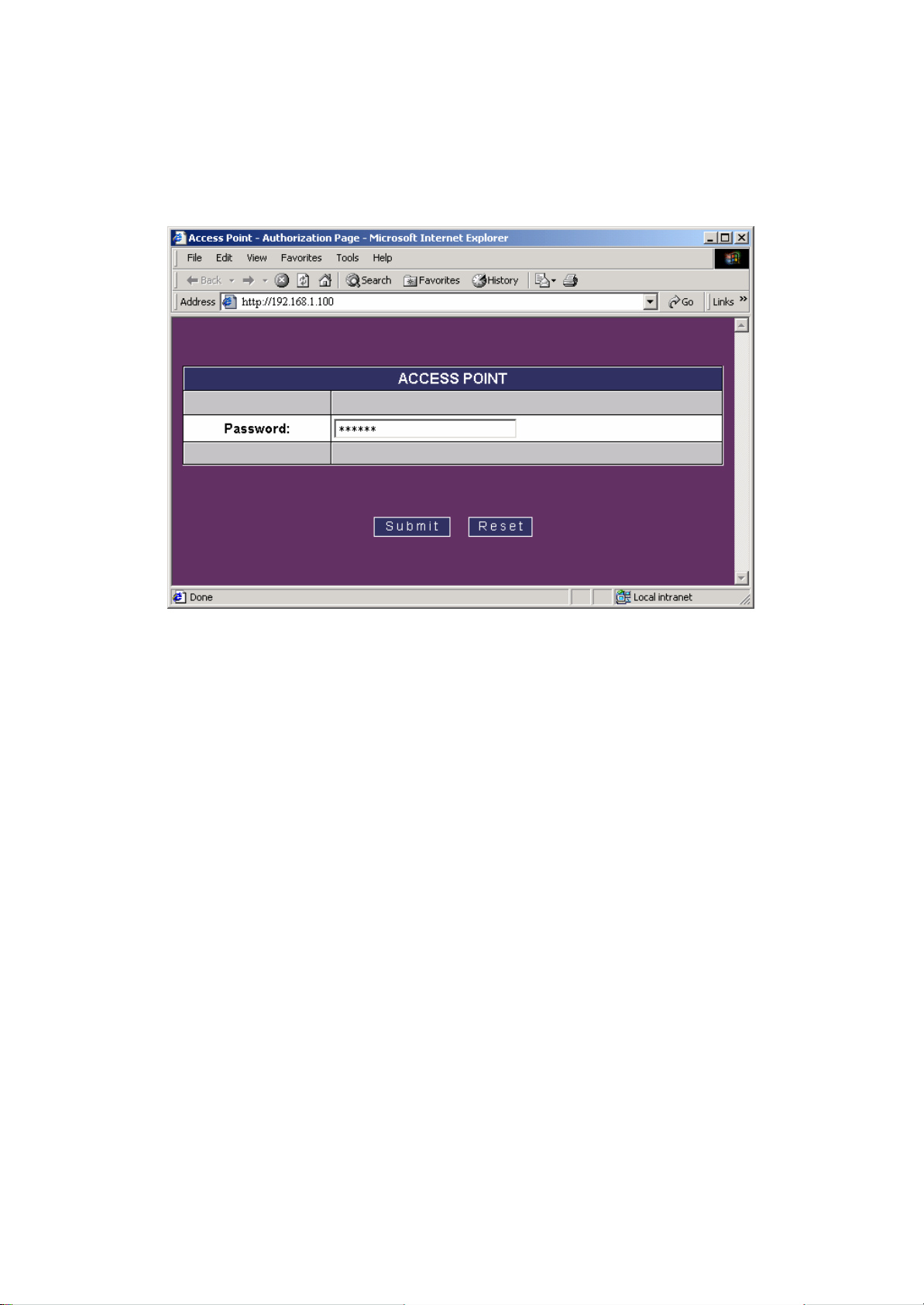
1) Launch web browser, and enter the AP’s default IP address, 192.168.1.100, in
the Address field. Then press Enter.
Page 18
17
2) A password request page will show, and enter “public”(the default password)
in the Password field. Then click the Submit button. Then you can monitor
and configure the Access Point.
If you have difficult y in using it, please click the Help for the detailed description about
how to operate the Web Manager.
Page 19
18
4. CONFIGURE AP AS BRIDGE - BLEND MODE (POINT TO MULTIPOINT
MODE AND POINT TO POINT SETTINGS)
4.1 Block Diagram
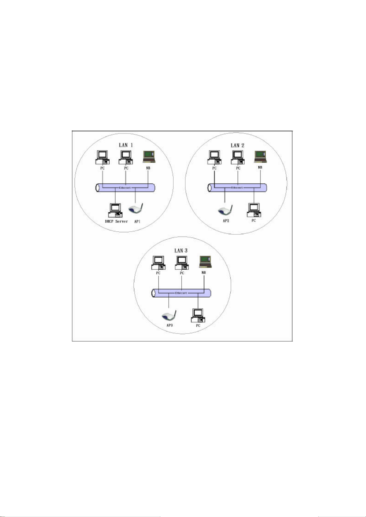
We assume that there are three LANs and they will be connected to each other via AP by
using AP bridge function. For three APs (AP1, AP2 and AP3) in the following diagram,
they can be configured to act as bridges via the SNMP Manager or the AP utility.
4.2 Configuration via SNMP manager
4.2.1 Open Access Point SNMP Manager window
See the description in section 3.2 to open the Access Point SNMP Manager from the PC
or NB.
Page 20
19
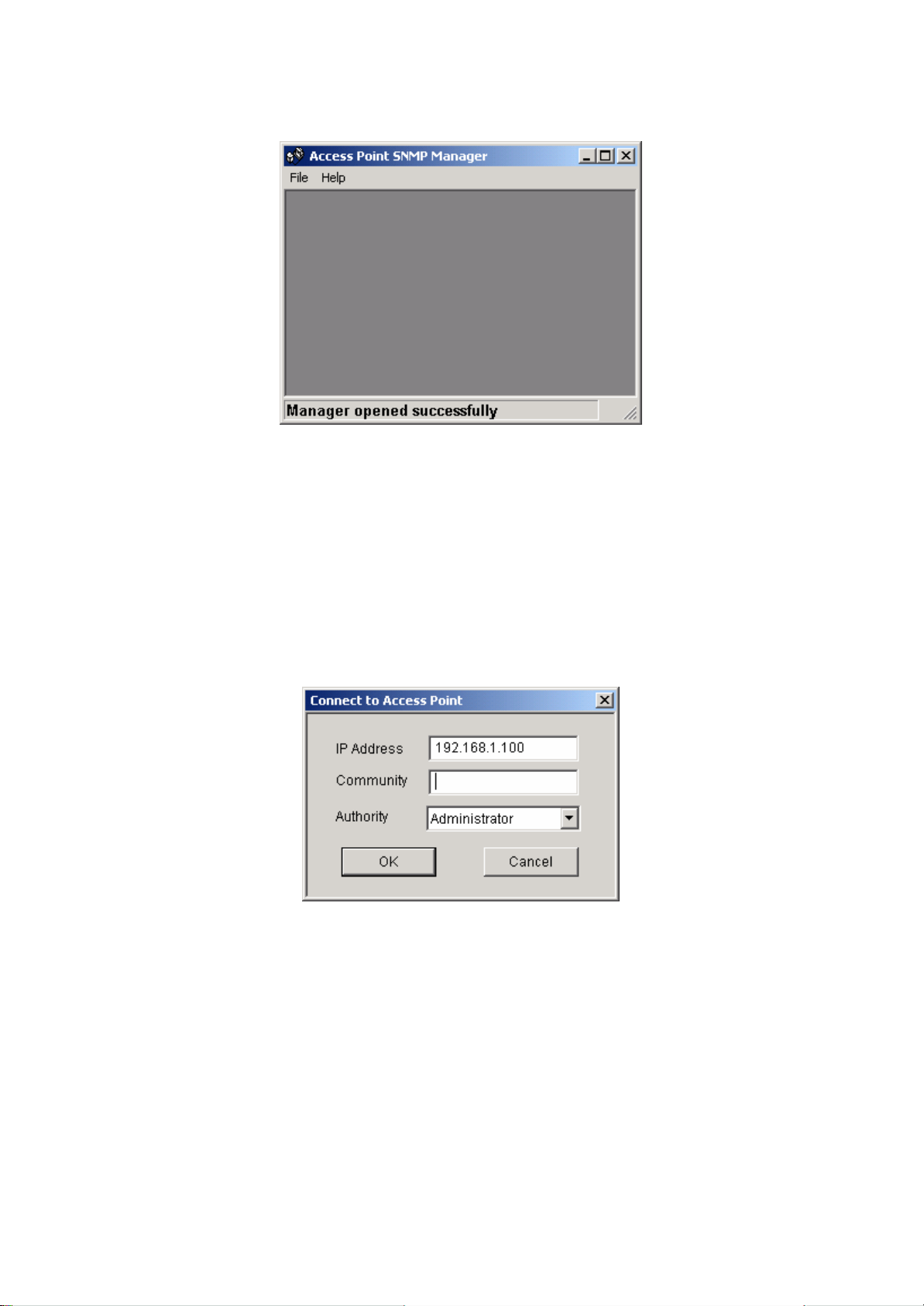
In the menu bar, click File, a pull-down menu will allow you to select Connect to Access
Point or Find Access Point:
If you know the AP’s IP address, then select Connect to Access Point.
If you do not know the AP’s IP address, then select Find Access Point. Wait for few
seconds, and select the right AP and click Connect.
Then the Connect to Access Point window will be displayed.
Enter the password in the Community field, which is already defined via the AP Utility.
Select Administrator in the Authority field. After clicking on OK button, the Access Point
SNMP Manager window will be displayed again with more items in the menu bar.
Page 21
20
4.2.2 Configuration procedure for bridge – blend mode
Follow the steps below to configure AP1:
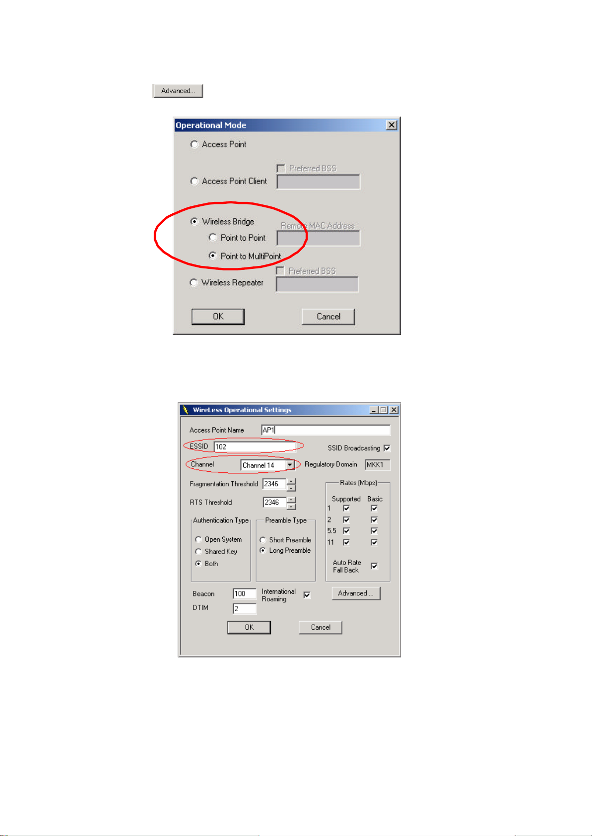
Step 1: Assign Point to Multipoint mode to AP1
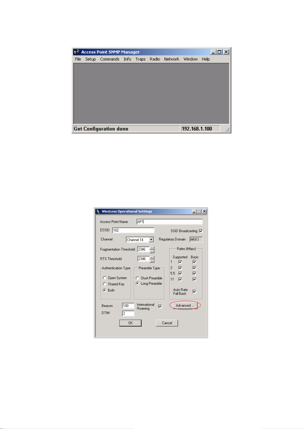
• At Access Point SNMP Manager window, click Setup, select Wireless LAN,
and then Operational Settings, the Wireless Operational Setting windows will
be displayed as follows:
Page 22
21
• Click on , the following window will be displayed.
• Select Wireless Bridge, and then Point to Multi Point, finally click on OK
button to go back to Wireless Operational Settings window.
Page 23
22
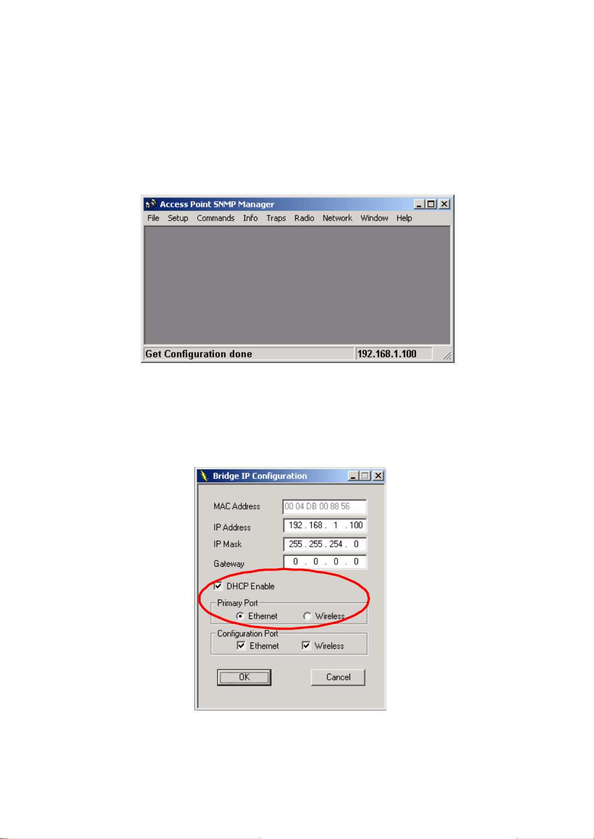
Step 2: Assign ESSID and Channel for AP1.
• At Wireless Operational Settings window, set values for ESSID and Channel
fields. The values for ESSID and Channel should be the same for all three
APs (AP1, AP2 and AP3), so they can be formed as a group and connected to
the available bridge AP. And then click on OK button to go back to the Access
Point SNMP Manager window.
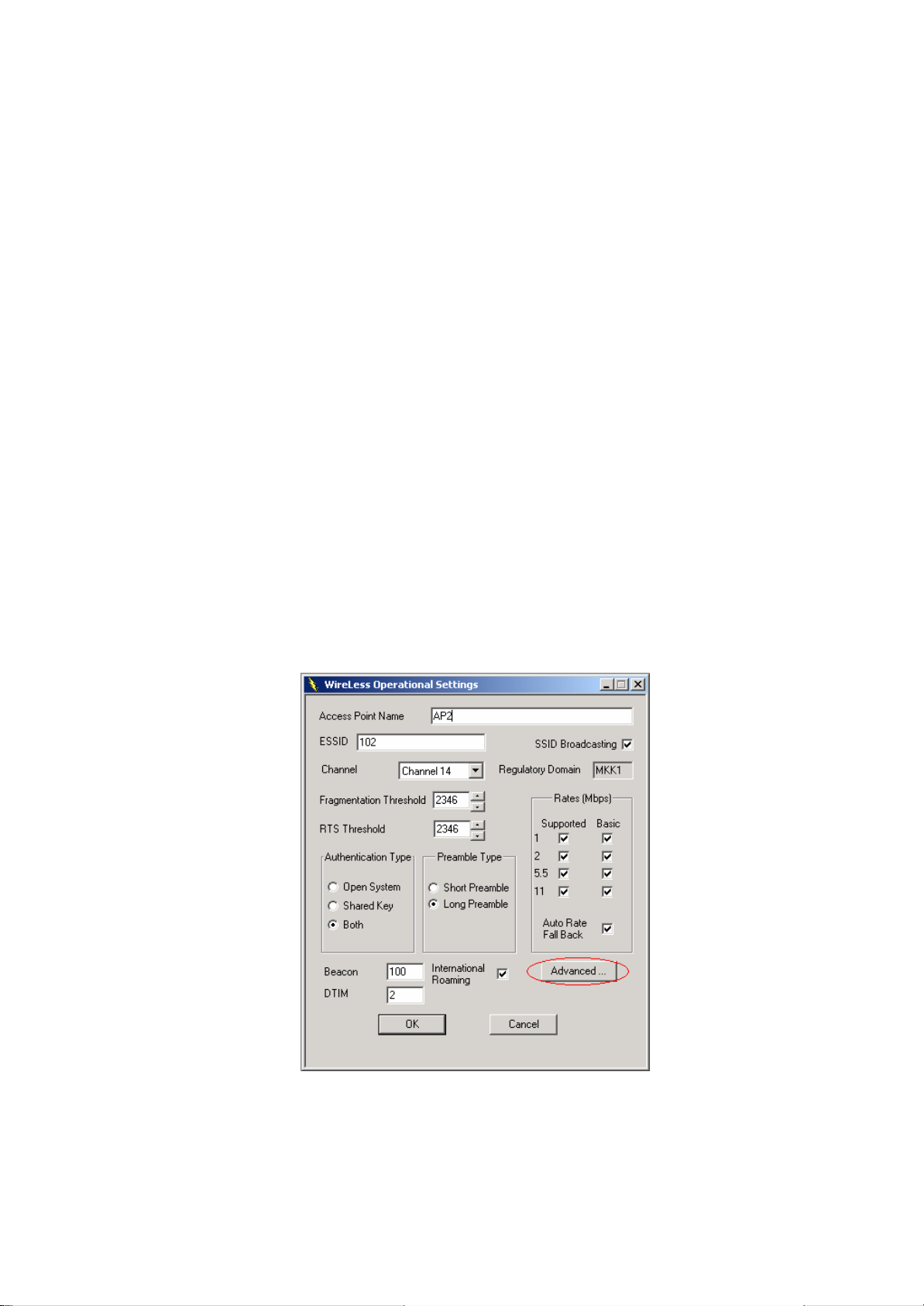
Step 3: Assign DHCP server accessing method for AP1.
• At Access Point SNMP Manager window, click Setup, select Bridge, and then
IP Configuration. The following window will be displayed.
Page 24
23
• Click DHCP Enable and select Ethernet in Primary Port, then click on OK
button to go back to the Access Point SNMP Manager window.
The Primary Port is the path for connecting DHCP Server to get IP address.
Because AP1 is connected to DHCP Server via Ethernet port, so the setting
must be Ethernet.
• Click File and select Download Changes, so all your changes will be
download to the AP1.
Step 4: Get AP1 MAC address
This value will be used by AP2 and AP3 to assign which device it will be communicated
with.
• Run SNMP Manager from the PC or NB in LAN1. Follow the same procedure
as described in step 3 to open the Access Point SNMP Manager window.
• At Access Point SNMP Manager window, click Setup, select Bridge, and then
IP Configuration. The Bridge IP Configuration window will be displayed.
Record the value in MAC Address field.
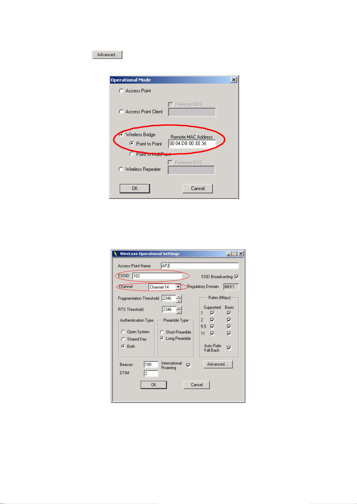
Step 5: Assign Point to Point mode and remote AP1’s MAC address to AP2/AP3.
• To PC/NB in LAN2/3 to configure AP2/3.
At Access Point SNMP Manager window, click Setup, select Wireless LAN,
and then Operational Settings. The following window will be displayed.
Page 25
24
• Click on .
The Operation Mode window will be displayed.
• At Operation Mode window, select Wireless Bridge and Point to Point, and
set AP1 MAC address into Remote MAC Address field, then click on OK
button to come back to Wireless Operational Settings window.
• Set values for ESSID and Channel fields. The values for ESSID and Channel
should be the same for AP1, AP2 and AP3, so they can be formed as a group
and communicate to each other. And then click on OK button to go back to
Page 26
25
Access Point SNMP Manager window.
Step 6: Assign DHCP server accessing method for AP2 and AP3.
• At Access Point SNMP Manager window, click Setup, select Bridge, and then
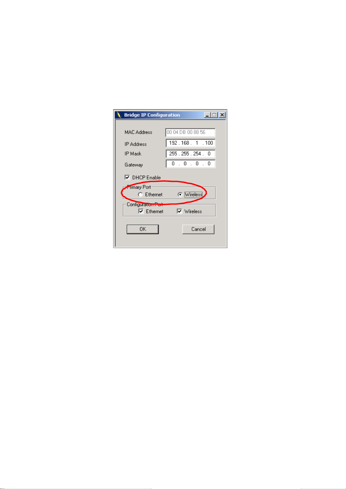
IP Configuration. The following window will be displayed.
• Click DHCP Enable and select Wireless in Primary Port, then click on OK
button.
The Primary Port is the path for connecting DHCP Server to get IP address.
However, AP2 and AP3 are connected with DHCP Server via wireless
connection, so the setting must be Wireless.
• Click File and select Download Changes to download the change to AP2 and
AP3.
When all settings are complete and correct, LAN1、LAN2 and LAN3 can use the same
ESS to connect to each other by wireless and let every PC or NB in LAN2 and LAN3 to
use LAN1’s DHCP Server.
In this mode, it is recommended that AP1, as a center AP, equip with omni-directional or
75 to 90-degree directional antennas. AP2 and AP3 can equip with directional antennas.
Page 27
26
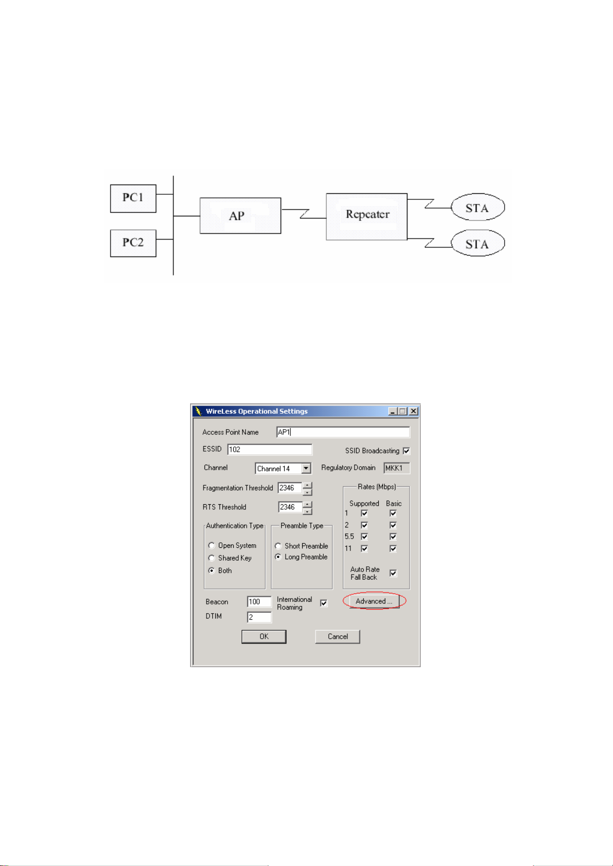
4.2.3 Wireless Repeater Mode
This mode is used in order to increase the coverage area of an ESS. The Wireless
Repeater starts acting as an AP after it has associated itself with another AP (Parent AP).
From that point on, STAs can get associated to it.
Follow the steps below to configure AP1:
Step 1: Assign Repeater mode to AP1
• At Access Point SNMP Manager window, click Setup, select Wireless LAN,
and then Operational Settings, the Wireless Operational Setting windows will
be displayed as follows:
Page 28
27
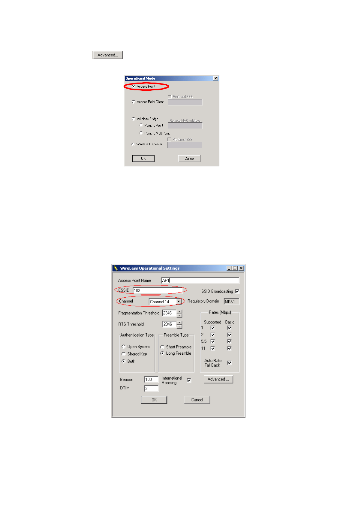
• Click on , the following window will be displayed.
• Select Access Point, finally click on OK button to go back to Wireless
Operational Settings window.
Step 2: Assign ES SID and Channel for AP1.
• At Wireless Operational Settings window, set values for ESSID and Channel
fields. The values for ESSID and Channel should be the same for AP2. And
then click on OK button to go back to the Access Point SNMP Manager
window.
Page 29
28
Step 3: Assign DHCP server accessing method for AP1.
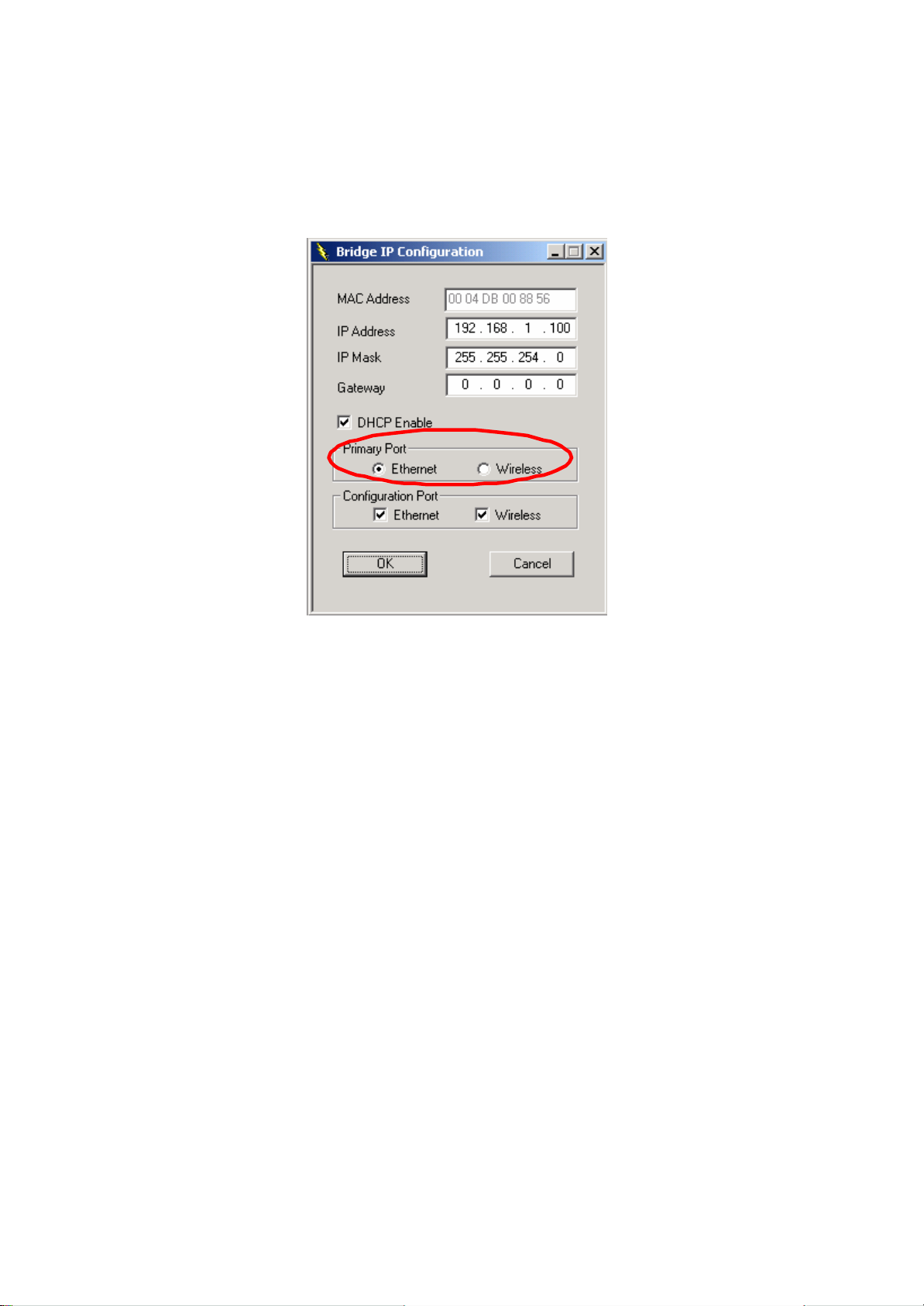
• At Access Point SNMP Manager window, click Setup, select Bridge, and then
IP Configuration. The following window will be displayed.
• Click DHCP Enable and select Ethernet in Primary Port, then click on OK
button to go back to the Access Point SNMP Manager window.
The Primary Port is the path for connecting DHCP Server to get IP address .
Because AP1 is connected to DHCP Server via Ethernet port, so the setting
must be Ethernet.
• Click File and select Download Changes, so all your changes will be
download to the AP1.
Step 4: Get AP1 MAC address
This value will be used by AP2 to assign which device it will be communicated with.
• Run SNMP Manager from the PC or NB in LAN1. Follow the same procedure
as described in step 3 to open the Access Point SNMP Manager window.
• At Access Point SNMP Manager window, click Setup, select Bridge, and then
IP Configuration. The Bridge IP Configuration window will be displayed.
Record the value in MAC Address field.
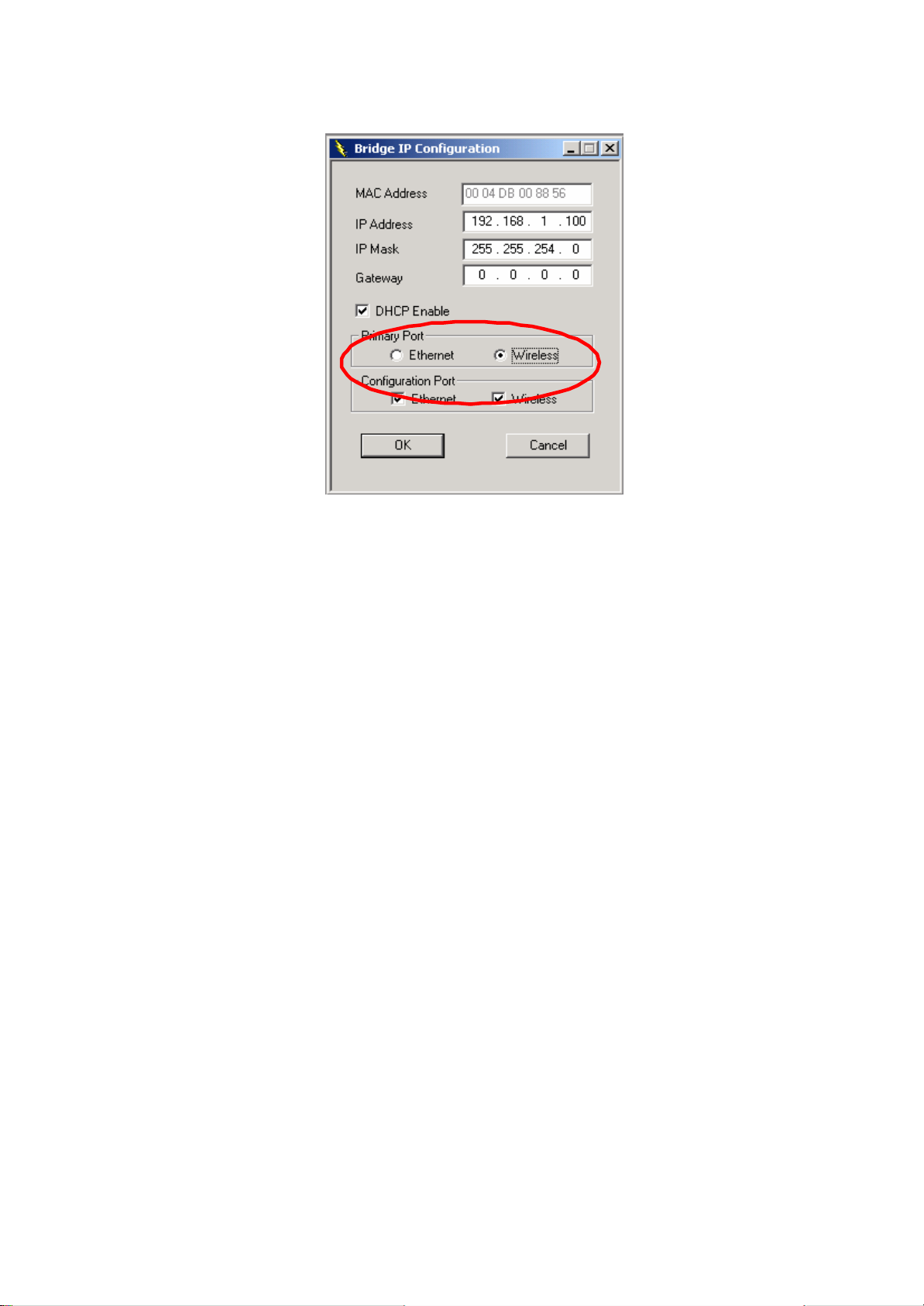
Step 5: Assign DHCP server accessing method for AP2.
• At Access Point SNMP Manager window, click Setup, select Bridge, and then
IP Configuration. The following window will be displayed.
Page 30
29
• Click DHCP Enable and select Wireless in Primary Port, then click on OK
button.
The Primary Port is the path for connecting DHCP Server to get IP address.
However, AP2 is connected with DHCP Server via wireless connection, so the
setting must be Wireless.
• Click File and select Download Changes to download the change to AP2.
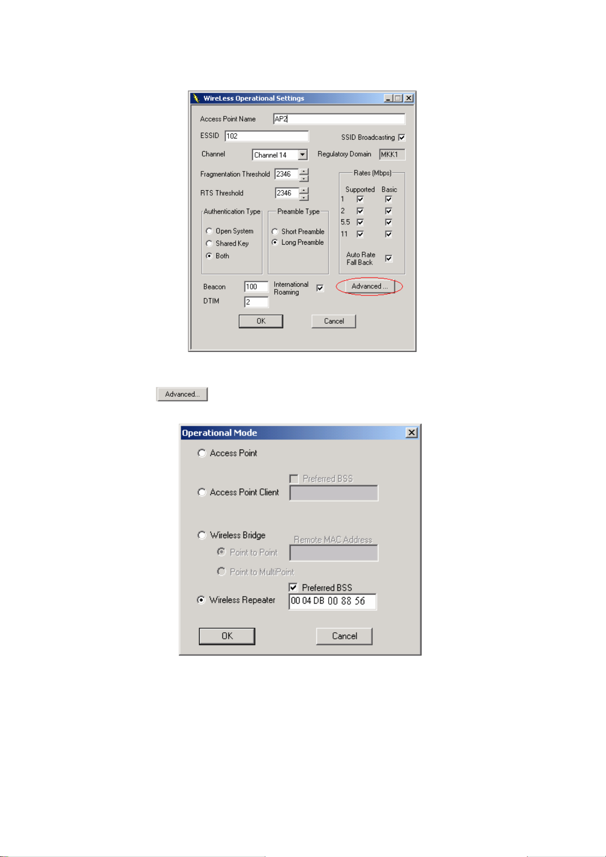
Step 6: Assign Repeater mode and remote AP1’s MAC address to AP2.
• At Access Point SNMP Manager window, click Setup, select Wireless LAN,
and then Operational Settings. The following window will be displayed.
Page 31
30
• Click on , the Operation Mode window will be displayed.
• At Operation Mode window, select Wireless Repeater, and set AP1 MAC
address into Remote MAC Address field, then click on OK button to come
back to Wireless Operational Settings window.
Page 32
31
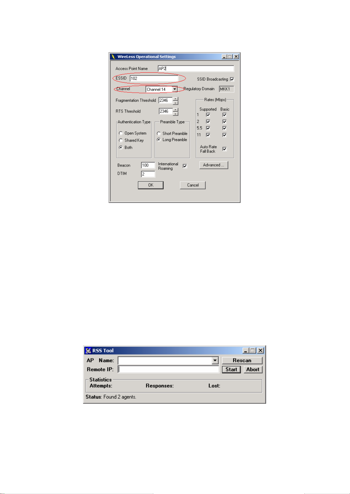
• Set values for ESSID and Channel fields. The values for ESSID and Channel
should be the same for AP1. And then click on OK button to go back to Access
Point SNMP Manager window.
Note: The Repeater can be configured with the SNMPManager through the wireless
STAs associated to it or the PCs in the Wired LAN behind the Parent AP.
4.3 Adjust the best angle of antenna
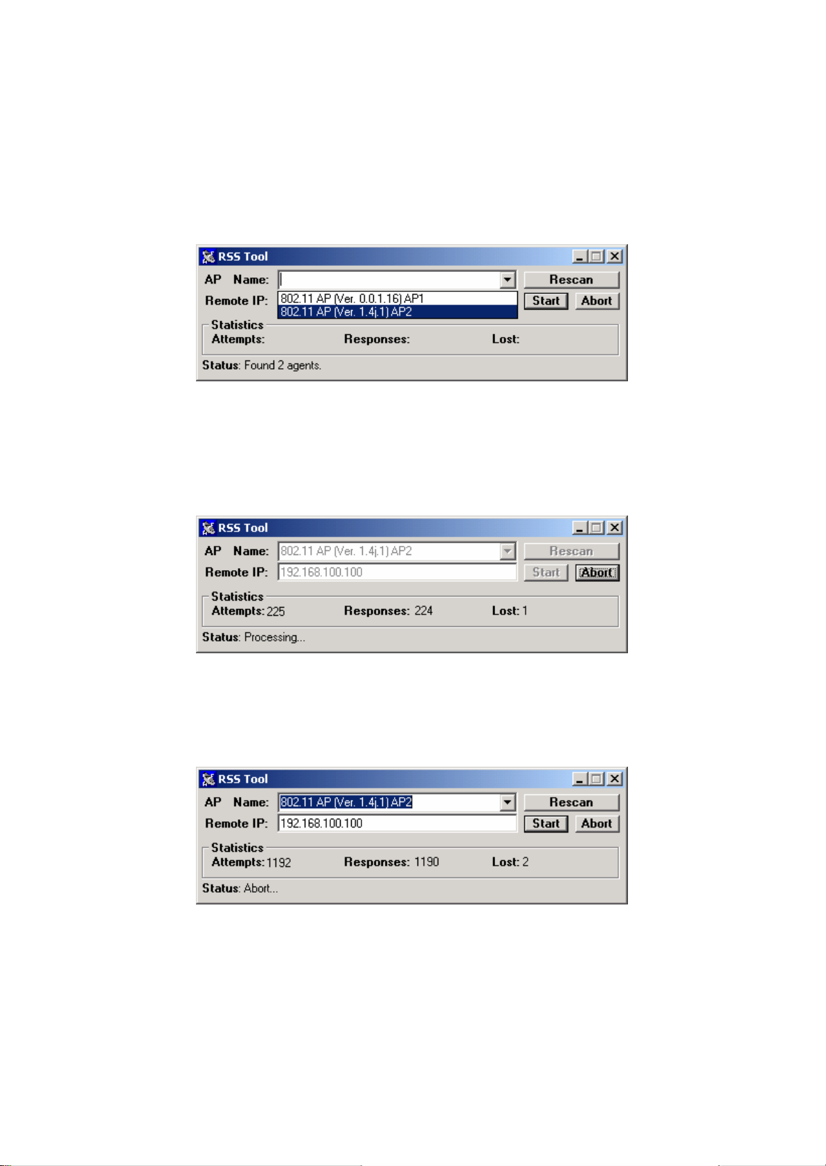
Step 1: Open RSSTool window
See the description in section 3.3 to open the RSSTool from the LAN1’s PC or NB.
Page 33
32
Step 2: Confirm the remote IP
If you know the AP2’s IP address, then type it in the “Remote IP” blank. If you do not
know the AP2’s IP address, then click Rescan. Wait for few seconds, and select the right
AP name from the pull-down menu.
Step 3: Click “Start” button
When you click the “Start” button, the RSSTool will sen d message to the AP2. You can
adjust the AP2’s antenna until AP2’s Led of RSS bright.
Step 4: Click “Abort” button
If you have adjusted the AP2’s antenna, you can stop this tool.
Step 5: Repeat the Step 1 ~ 4 at LAN2’s PC or NB
When you finish the step 5, you will get the best angle of antennas. Then AP1 and AP2
can communicate with the best quality.
Note: When RSSTool is running, you can’t run SNMP Manager at the same time.
Page 34

33
5. SPECIFICATIONS
General
Standards
IEEE 802.3 and 802.11b
compliance
Security WEP 64 -bit, 128-bit, encryption RC4
Hardware
RF Frequency range: 2.4 ~ 2.4835GHz
Data rate 11Mbps / 5.5Mbps / 2Mbps / 1Mbps
DSSS (Direct Sequence Spread Spectrum) Modulation
DBPSK/DQPSK
1, 2Mbps: 11 chip/bit Barker Coding Coding
5.5, 11Mbps: Complementary Code Keying
Number of channels
Europe: 13 (3 non-overlapping)
US: 11 (3 non-overlapping)
France: 4 (1 non-overlapping)
Japan: 14 (3 non-overlapping)
RJ-45 Host interface
USB (local configuration)
Transmit power +20dBm (Min.)
Receive sensitivity -83dBm (Typ.) for 11Mbps
Power <750mA @ 5Vdc
Range Open environment: up to 300m (985ft)
Office environment:
up to 30m(98ft ) @ 11Mbps
up to 40m (131ft) @ 5.5Mbps
up to 60m (197ft) @ 2Mbps
up to 100m (328ft) @ 1Mbps
Range for the AP depends on many factors and can vary
greatly dependin g on the environment. The actual range may
be less than stated.
Software
Local: AP Utility under Windows 98/2000/Me/XP Management
interface
Remote: SNMP under Windows 98/2000/Me/XP/NT
Mechanical
Antenna One external antenna
Indicator LAN, Duplex, Power, WLAN
Environmental 0 ~ 55°C (operation), -20 ~ +65°C (storage)
Page 35

34
Relative Humidity 95% (non-condensing)
Dimensions 6.6” x 4.6” x 1.4” (167.0 x 117.5 x 35.5 mm), without antenna
Weight 12.3 oz. (350 grams), excluding power adapter
Certificate
U.S.: FCC Part 15, sections 15.247, 15.205, 15.209 EMC
Europe: ETS 300 328, ETS 300 826, CE Marked
Page 36

35
6. GLOSSARY
The following glossary is for your reference, and is not directly related to the installation
of your Access Point.
- Wireless Access Point (AP) – Any entity that has station functionality provides
access to the distribution services via the wireless medium (WM) for associated stations.
- Ad-Hoc – A network is composed solely of stations within mutual communication
range of each other via the wireless medium (WM). An ad hoc network is typically
created in a spontaneous manner. The principal distinguishing characteristic of an ad hoc
network is its limited temporal and spatial extent. These limitations allow the act of
creating and dissolving the ad hoc network to be sufficiently straightforward and
convenient so as to be achievable by non-technical users of the network facilities; i.e., no
specialized technical skills are required and little or no investment of time or additional
resources is required beyond the stations that are to participate in the ad hoc network. Ad
hoc is often used as a slang term to refer to an independent basic service set (IBSS).
- BSS (Basic Service Set) – An AP is associated with several wireless stations.
- ESS (Extended Service Set) – More than one BSS can be configured as an Extended
Service Set. An ESS is basically a roaming domain.
- Ethernet – A popular local area network, originally developed by Xerox Corp.,
accepts transmissions from computers and terminals. Ethernet operates on 10 Mbps
baseband transmission over shielded coaxial cable or over shielded twisted pair telephone
wire.
- Fragmentation Threshold Value – Indicates how much of the network resources is
devoted to recovering packet errors. The value should remain at its default setting of 2,436.
If you experience high packet error rates, you can decrease this value but it will likely
decrease overall network performance. Only minor modifications of this value are
recommended.
- Infrastructure – The infrastructure includes the distribution system medium (DSM),
AP, and portal entities. It is also the logical location of distribution and integration service
functions of an extended service set (ESS). An infrastructure contains one or more APs
and zero or more portals in addition to the distribution system (DS).
- IEEE – Institute of Electrical and Electronic Engineering
- LAN – Local Area Network
- Open System – Is when the sender and the recipient do not share a secret key.
Each party generates its own key -pair and asks the receiver to accept the (usually
randomly) generated key. Once accepted, this key is used for a short time only;
then a new key is generated and agreed upon.
- Roaming – A function allows one to travel with a mobile end system (wireless LAN
mobile station, for example) through the territory of a domain (an ESS, for example)
while continuously connecting to the infrastructure.
- RSS – Receive Signal Strength
Page 37

36
- RTS/CTS Threshold – Should remain at its default setting of 2,346. A preamble is a
signal used to synchronize the transmission timing between two or more systems. A series
of transmission pulses is sent before the data to indicate that “someone is about transmit
data.” This ensures that systems receiving the information correctly when the data
transmission starts.
- Shared Key – Is when both the sender and recipient share a secret key. Both units
use this key for an extended length of time, sometimes indefinitely. Any
eavesdropper that discovers the key may decipher all packets until the key is
changed.
- SOHO – Small Office Home Office
- SSID – Is the unique name shared among all points in a wireless network. The
SSID must be identical for all points in the network. It is case sensitive and must
not exceed 32 characters.
- Wired Equivalent Privacy (WEP) – The optional cryptographic confidentiality
algorithm specified by IEEE 802.11 provides data confidentiality that is subjectively
equivalent to the confidentiality of a wired local area network medium that does not
employ cryptographic techniques to enhance privacy.
Page 38

37
7. DEFAULT SETTINGS
No. Identifier Description Default Value Possible Values
1 Eth_IP_Address AP’s IP address 192.168.1.100
2 Eth_SubMask Subnet mask 255.255.255.0
3 ESSID Extended service set ID WLAN-AP
4 Auto Rate Fall
Back
Transmission rate is
subject to the past
Enable “Enable”, “Disable”.
transmission status.
5 Channel Designate operating
radio channel
1 for FCC, IC,
ETSI, MKK. 10
for others.
FCC/IC: 1 to 11,
ETSI: 1 to 13,
Spain: 10 to 11,
France: 10 to 13,
MKK: 1 to 14.
6 Fragmentation
Threshold
The size at which
packets will be
2346 “256” to “2346 ”
bytes.
fragmented.
7 RTS Threshold Minimum size to enable
RTS/CTS mechanism
8 WEP Type Type of Wired
Equival ent Privacy
2346 (stands for
disabled)
“256” to “2346 ”
bytes.
Disable “Disable”, “64-bit
WEP”, “128-bit
WEP”.
9 WEP Key WEP keys to be used. Key1 “Key1 ”, “Key2”,
“Key3 ”, “Key4”.
10 Key64 1 64-bit WEP value of
key 1
10 11 12 13 14
“00” to “FF” for
each field.
11 Key64 2 64-bit WEP value of
key 2
12 Key64 3 64-bit WEP value of
key 3
13 Key64 4 64-bit WEP value of
key 4
128-bit WEP value of
14 Key128 1 128-bit W EP value of
key 1
20 21 22 23 24
30 31 32 33 34
40 41 42 43 44
10 11 12 13 14
00 00 00 00 00
00 00 00
“00” to “FF” for
each field.
“00” to “FF” for
each field.
“00” to “FF” for
each field.
“00” to “FF” for
each field.
Page 39

38
No. Identifier Description Default Value Possible Values
15 Key128 2 128-bit WEP value of
key 2
16 Key128 3 128-bit WEP value of
key 3
17 Key128 4 128-bit WEP value of
key 4
18 Preamble Type The appropriate frame
format for transmission
to physical layer.
19 Authentication
Type
“Open System”: the
access to AP is valid if
the security key of
station is not set.
“Shared Key”: the
access to AP is valid if
the security key of
station matches with
AP’s.
“Both”: both “Open
System ” and “Shared
Key” and are
applicable.
20 21 22 23 24
00 00 00 00 00
“00” to “FF” for
each field.
00 00 00
30 31 32 33 34
00 00 00 00 00
“00” to “FF” for
each field.
00 00 00
40 41 42 43 44
00 00 00 00 00
“00” to “FF” for
each field.
00 00 00
Long “Short”, “Long”.
Both Type “Open System”,
“Shared Key”,
“Both ”.
20 Access Point
Name used for the AP Access Point
Name
21 Operational
Rate Set
Range of applicable
data rate
22 Beacon Pe riod Duration between
beacon packets
23 DTIM Interval of AP sends its
broadcast traffic
82 84 8b 96 “82 84 8b 96” for 1
to 11Mbps, “82 84
0b 16” for 1 to 2
Mbps.
100 20 to 1000
milliseconds.
2 (beacons)
Page 40

39
No. Identifier Description Default Value Possible Values
AP broadcasts the
24 Operational
Mode
25 User
Community
Which operation mode
is taken
The user password used
for SNMP
26 User Access User access rights used
for SNMP
27 Administrator
Community
The administrator
password used for
SNMP
28 Administrator
Access
29 Gateway IP
Address
Administrator access
rights used for SNMP
IP address of the
gateway
Access Point “WBridge Point to
MultiPoint ”,
“Access Point”,
“Access Point
Client ”, “WBridge
Point to
Point”, ”Wireless
Repeater”.
public
READ ONLY “READ ONLY”,
“READ\WRITE”.
public
READ \WRITE “READ ONLY”,
“READ\WRITE”.
0.0.0.0
30 IP Filtering Allow only IP packets
31 DHCP Client Automatic IP address
32 Primary Port Port connects to DHCP
33 Authorization
Algorithm
34 SNMP Traps The message indicates
35 Preferred BBS Remote MAC address
36 SSID
Broadcasting
to pass through the
WLAN
assignment by the
DHCP server
server
Enable authorized MAC
address stations to
access AP.
the AP’s actions.
for connection in the
operational mode of
Access Point Client or
Wireless Bridge.
ESSID to the stations
Disable “Enable”, “Disable”.
Enable “Enable”, “Disable”.
Ethernet “Ethernet”,
“Wireless”.
Disable “Enable”, “Disable”.
Enable “Enable”, “Disable”.
00 00 00 00 00
00
“00” to “FF” for
each field.
Enable “Enable”, “Disable”.
Page 41

40
No. Identifier Description Default Value Possible Values
The AP send back to
the air roadcast traffic
The AP forward
broadcast traffic to the
The AP send back to
the air unicast traffic
37 Send Back
Broadcast
Enable
38 Forward
Broadcast
Enable
39 Configuration
Port
40 Send Back
Unicast Enable
41 International
Roaming
Enable
received from the air.
air.
Port will be used for
the AP configuration.
received from the air.
AP support the
International
Roaming function
Enable “Enable”, “Disable”.
Enable “Enable”, “Disable”.
Both Ports “Both Ports”,
“Ethernet Port”,
“Wireless Port”.
Enable “Enable”, “Disable”.
Enable “Enable”, “Disable”.
42 802.1x Enable Start the 802.1x
authentication schema
43 Broadcast Key
Period
44 Server IP
Address
Duration between
Broadcast Key
RADIUS Server’ s IP
address
45 Server Secret The shared key used by
the AP and RADIUS
Server during the
authentication process.
Disable “Enable”, “Disable”,
“802.1x Mixed
Environment” .
0 0-65535
0.0.0.0
“”
Page 42
41
8. WIRELESS LAN SYSTEM
The contents in this section, which are not directly related to the installation of your
Access Point, are for you to have better understanding of a Wireless LAN system.
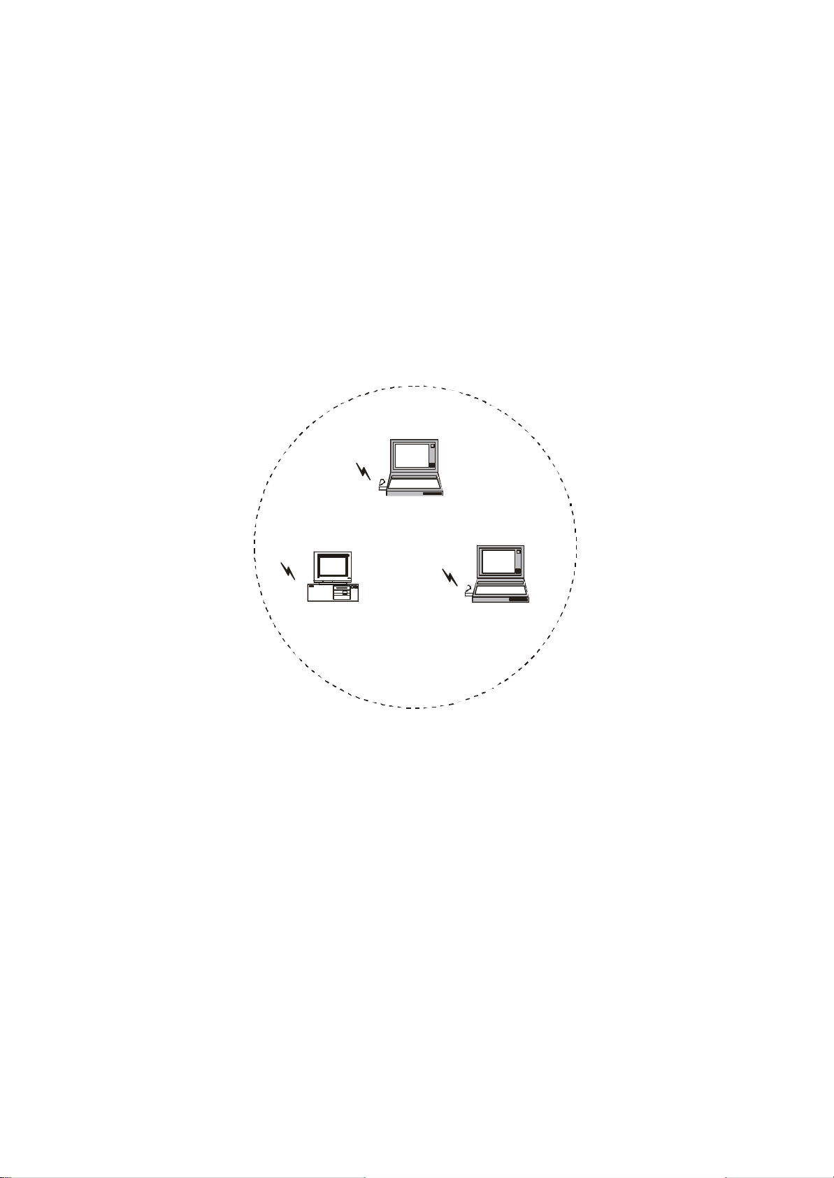
8.1 802.11 Ad-Hoc Configuration
An 802.11 Ad-Hoc wireless LAN is a group of computers, each equipped with one
wireless LAN card, connected as an independent wireless LAN. Computers in a specific
802.11 Ad -Hoc wireless LAN must be configured at the same radio channel and BSS ID.
802.11 Ad -Hoc wireless LAN is applicable to a departmental scale for a branch or SOHO
operation.
Notebook with Wireless PC Card
Desktop PC with
Wireless PC Card
Notebook with
Wireless PC Card
Figure 1. 802.11 Ad-Hoc Configuration
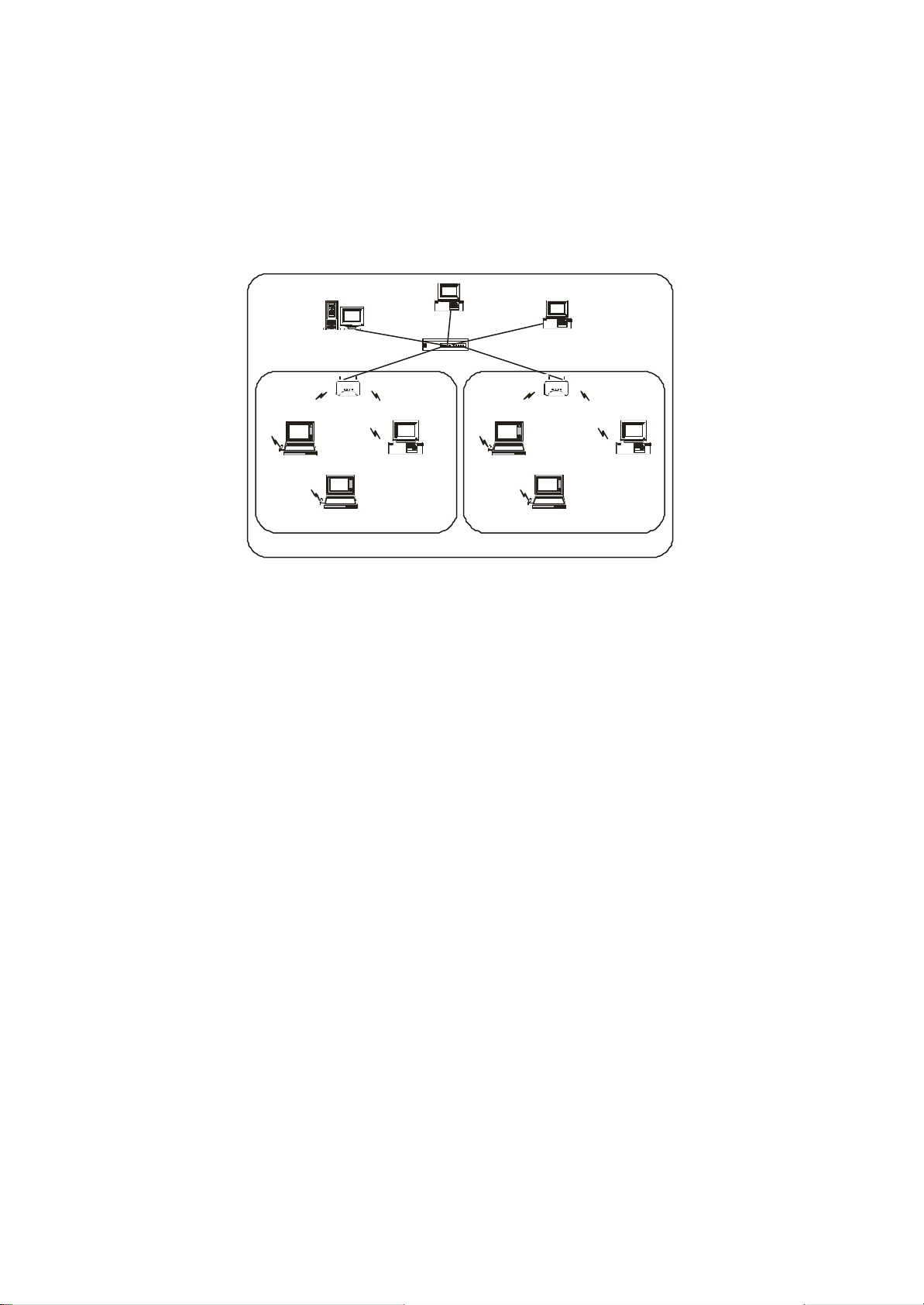
8.2 Infrastructure Configuration
An integrated wireless and wired LAN is called an infrastructure configuration. A group
of wireless LAN cards and an Access Point (AP) is called a Basic Service Set (BSS).
Each wireless LAN card in this BSS can be linked to any computer in the wired LAN
infrastructure via the AP.
Infrastructure configuration not only extends the accessibility of a wireless LAN card to
the wired LAN, but also doubles the effective wireless transmission range between two
wireless LAN cards.
BSS ID is, in essential, the ID of each independent wireless LAN card. All wireless LAN
cards configured without roaming options in this independent BSS must be configured
with BSS ID of that AP. You may need to check BSS ID of your AP by using its vendor
supplied program.
Page 43
42
Infrastructure configuration is applicable to enterprise scale for wireless access to central
database, or wireless application for mobile workers.
Two APs can be used as a point-to-point link between two LANs. LAN interconnection is
applicable to a wireless backbone between buildings.
Desktop PC
File Server
Hub
Access Point Access Point
Desktop PC
Notebook with
Wireless PC Card
Notebook with Wireless PC Card Notebook with Wireless PC Card
BSS1 BSS2
Desktop PC with
Wireless PC Card
ESS
Notebook with
Wireless PC Card
Desktop PC with
Wireless PC Card
Figure 2. Infrastructure Configuration
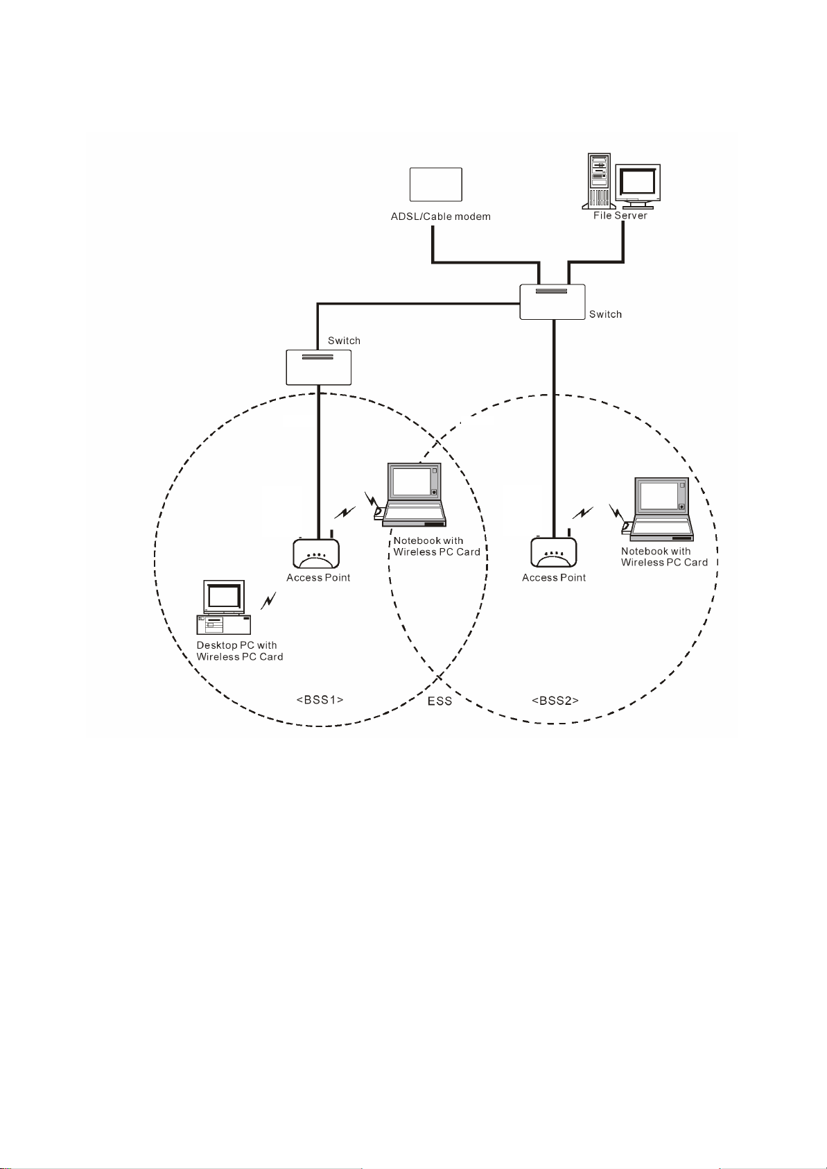
The infrastructure configuration supports roaming capability for mobile workers. More
than one BSS can be jointly configured as an Extended Service Set (ESS). On account of
a continuous connection to the network, users within this ESS can roam freely. All
wireless LAN cards and APs within one ESS must be configured with the same ESS ID.
Before setting up an ESS for roaming, it would be helpful to achieve good performance
by choosing a feasible radio channel and right places for APs.
Page 44
43
Figure 3. Seamless Roaming
Page 45
44
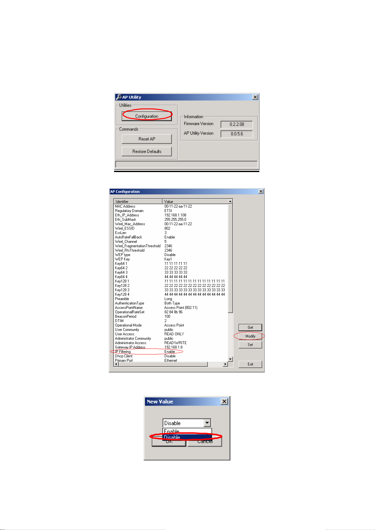
9. DISABLE IP FILTERING
Use AP Utility to disable IP Filtering
1) Run AP Utility, then click Configuration.
2) If the item IP Filtering is not Disable, click Modify.
3) Select Disable, then click OK.
Page 46
45
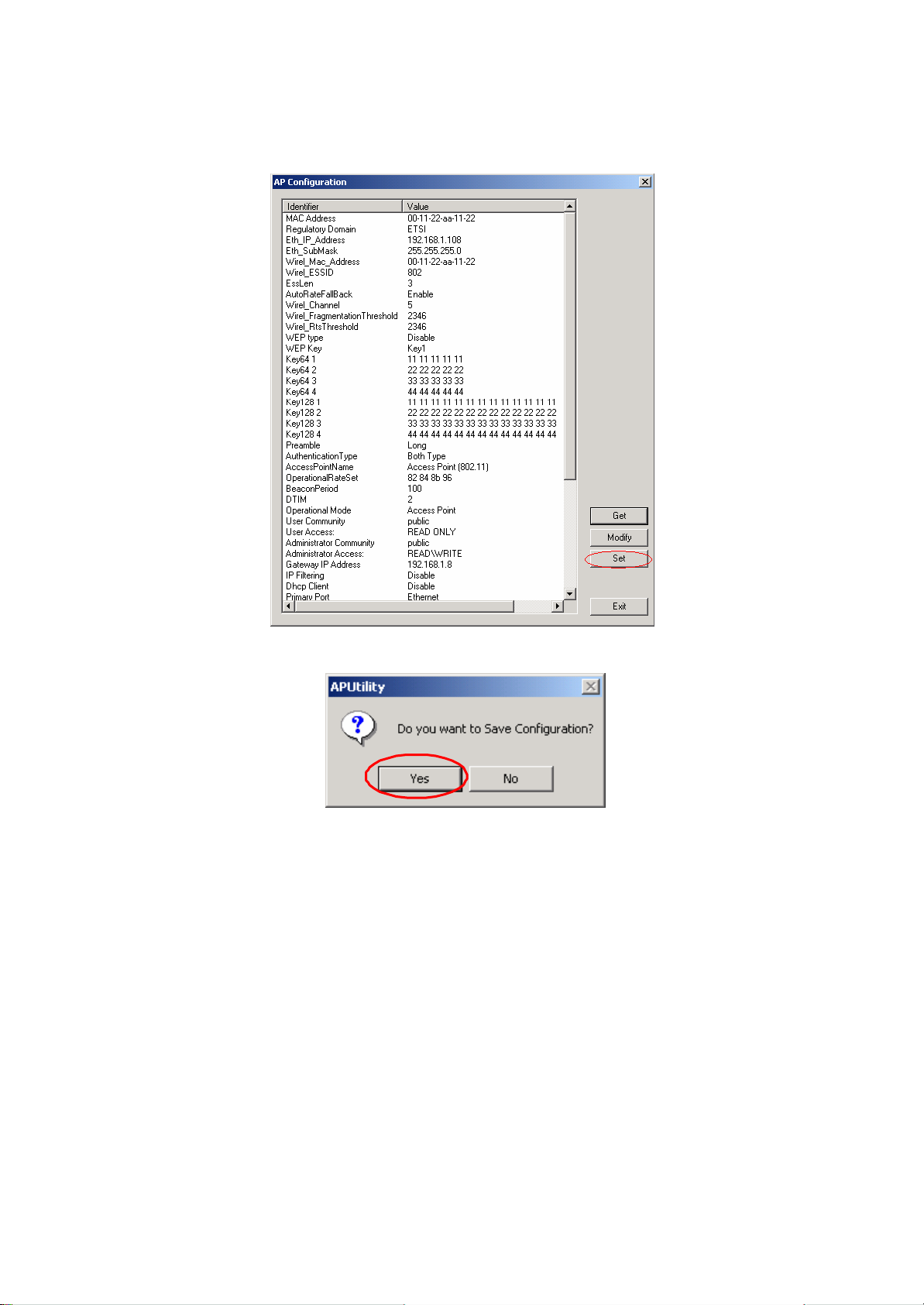
4) Click Set.
5) Click Yes, then wait for download completion.
6) Exit AP Utility.
7)
Page 47
46
Use SNMP Utility to disable IP Filtering
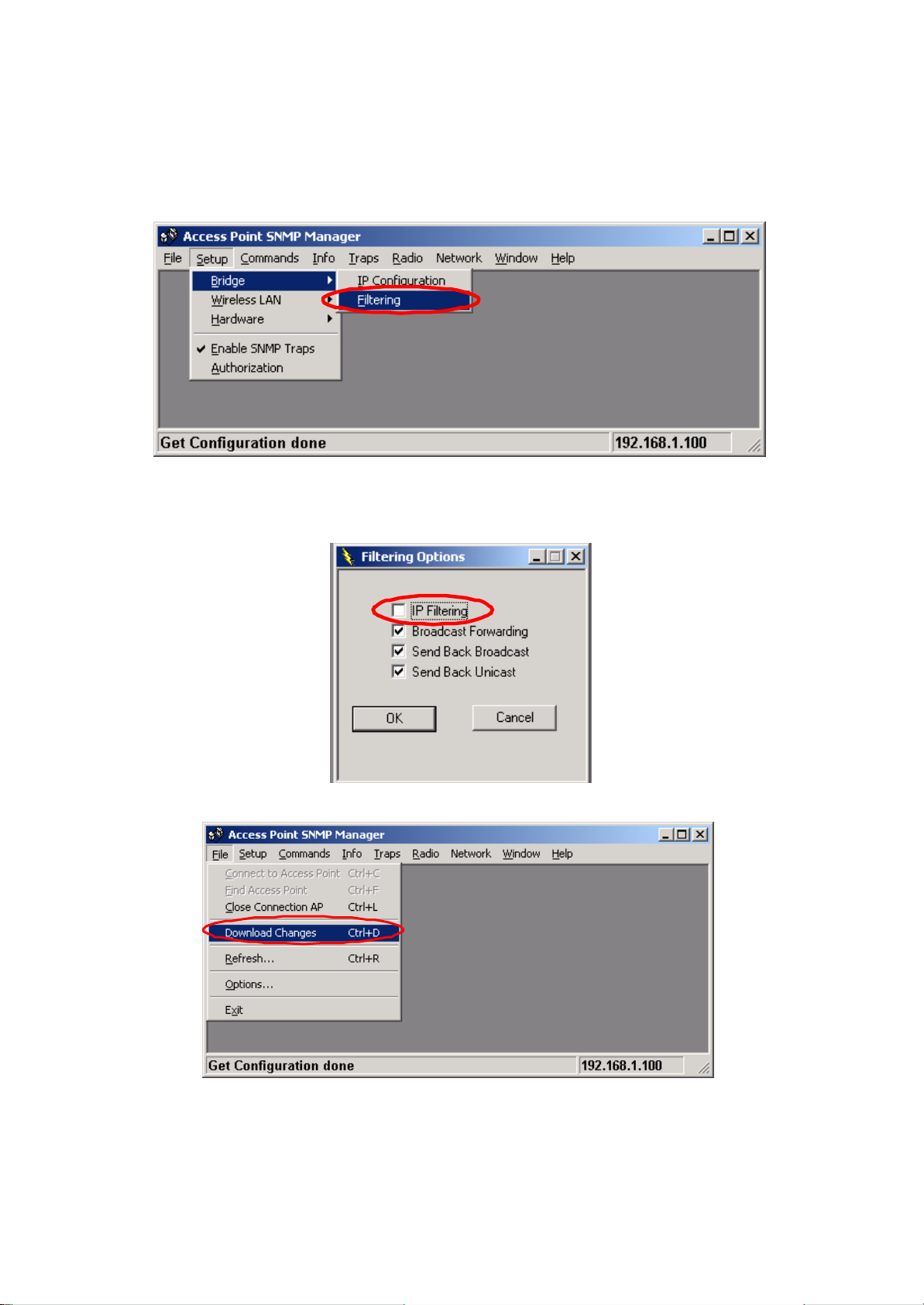
1) Run SNMP, then press Setup -> Bridge -> Filtering
2) Un-check IP Routing, then click OK.
3) Press File -> Download Change .
4) Exit SNMP Utility.
 Loading...