

Page 1

EasyCon GSM
Installation manual
Page 2

EasyCon GSM
CONTENTS
Description of device functions ........................................................................ page 3.
Description of the terminal block .................................................................... page 3.
Installation instructions ....................................................................................... page 3.
LED signals ............................................................................................................... page 3.
Reset (factory default) .......................................................................................... page 4.
Control with caller ID function .......................................................................... page 4.
Output settings ...................................................................................................... page 4.
Input settings .......................................................................................................... page 5.
Power monitor ........................................................................................................ page 5.
tellsystem.eu
Tamper ....................................................................................................................... page 6.
Life signal .................................................................................................................. page 6.
SMS forward ............................................................................................................ page 6.
Description of voice calls .................................................................................... page 6.
Description of SMS ................................................................................................ page 7.
Calendar of events ................................................................................................ page 7.
Expansion module ................................................................................................ page 7.
Signal strength monitoring ............................................................................... page 7.
SMS programming ................................................................................................ page 7.
Monitoring station ................................................................................................ page 9.
Software updates .................................................................................................. page 9.
Connected battery ............................................................................................. page 10.
Other commands ................................................................................................ page 10.
Circuit diagram .................................................................................................... page 10.
Frequently asked questions and answers .................................................. page 10.
CE certificate ......................................................................................................... page 11.
page 2. TellSystem Communication
Page 3
EasyCon GSM
tellsystem.eu
Description and functions of the device
• the GSM communicator may be used as a complement to alarm control systems as a 2 input GSM transmitter.
• capable of sending voice or SMS messages to 8 phone numbers. Voice messages with a length of up to 8 seconds can be sent
concerning the 2 inputs and power failure. An extra identification message may be recorded (up to 16 seconds), which is played
before the alarm message.
• the open collector (OC) output of the device may be used for control with caller ID.
• capable of forwarding SMS messages received by the SIM card to a preset phone number.
• monitors power failure and GSM signal strength; GSM signal strength can be read out and drawn up as a one-hour resolution
graph with the programming software.
• possesses a 16.000 event list, which records signals, GSM status, incoming calls and phone numbers.
• PC programming is possible with ProRead software and optional programming cable!
Description of the terminal block
I2, C, I1 Input2 and Input1 controlled by short-circuit or cut in relation to COM port
O Output of the module: OC=open collector
+, - Power supply: += 9-18 VDC; -= GND
Installation instructions
• Check signal strength with your mobile. It is possible that signal strength is not sufficient at the desired place. If so, modify device
location before installation.
• Locate device far from electromagnetic interferences, such as electric motors, or transformer of the alarm system.
• Do not install device in wet or high humid places.
• Connection of the antenna: You may connect the antenna to a SMA plug. In case of poor signal strength use a higher gain an-
tenna.
• Disable PIN requirement, voice mail, and call notification on your SIM card.
• Occasionally a newly bought SIM card needs to be activated (usually by making an outgoing call).
• Caller ID function needs to be activated on your SIM card by the Mobile Service Provider (with some models it is not activated
by default).
• Insert SIM card.
• Connect antenna to device.
• Connect as indicated.
• Device is ready to be connected to power supply. Make sure that the power supply is sufficient for the operation of the device.
The module’s resting current is 20mA, but may reach 300mA during communication.
• After connecting to the power supply, the red LED goes on, which indicates that the device is trying to contact the GSM tower
(up to 1 min).
• When the red LED light goes off and the green LED is flashing, the module is ready for operation and has connected to the network. The number of flashes indicates signal strength.
• For programming the power supply needs to be connected.
LED signals
LED status = green
ACT LED = red
Number of flashes: Number of LED flashes between the breaks.
Only green LED flashes No error, GSM module connected, the number of LED flashes shows signal strength.
1..2=poor signal strength, 3=sufficient, 4..5=excellent
Green LED on GSM module’s connection rejected.
Red LED on Shows initialization on start-up, otherwise an event message is being sent (SMS, voice
call).
page 3. TellSystem Communication
Page 4
EasyCon GSM
tellsystem.eu
Green and red flashes at the same
time
Error code by the number of flashes:
1 flash: GSM module initialisation
2 flashes: GSM module defective
3 flashes: SIM card not inserted
4 flashes: SIM card blocked by PIN code
10 flashes: Modem mode
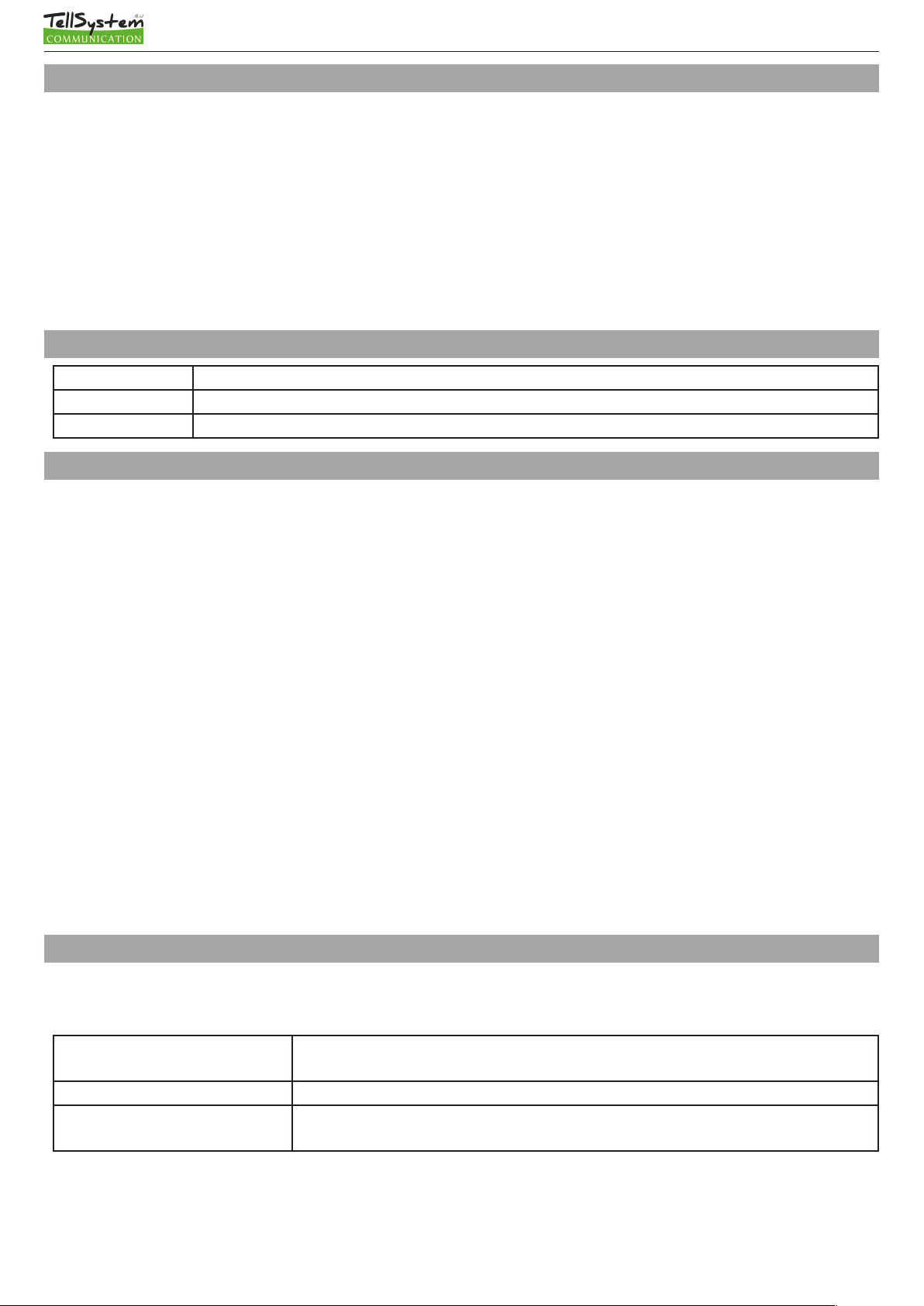
Control with caller ID function
You need to have your Service Provider enable the caller ID function in the SIM card of your GSM module. The caller ID function
needs to be enabled in each telephone from which you would like to control the device.
The GSM module accepts phone numbers stored on the SIM card, therefore depending on the SIM card 250 or 500 numbers can
be set. You may add phone numbers to the SIM card by inserting it to a regular mobile phone, or you may view/edit the SIM card’s
address book in the Caller ID tab. First you need to upload it with the Read button, then after editing write it in with the Send button. The address book can be imported/exported in EXCEL csv format with the Open/Save button.
The caller ID function can be switched off in the GSM module (Output tab / Control with Caller ID), in this case the device accepts
every phone number. The caller ID function can be used for output control (Output tab / Control with Incoming Call). The module
provides feedback about status with the number of ringtones:
- Output control in bistable mode: few ringtones (0-1) = control, many ringtones (3-4) = end of control
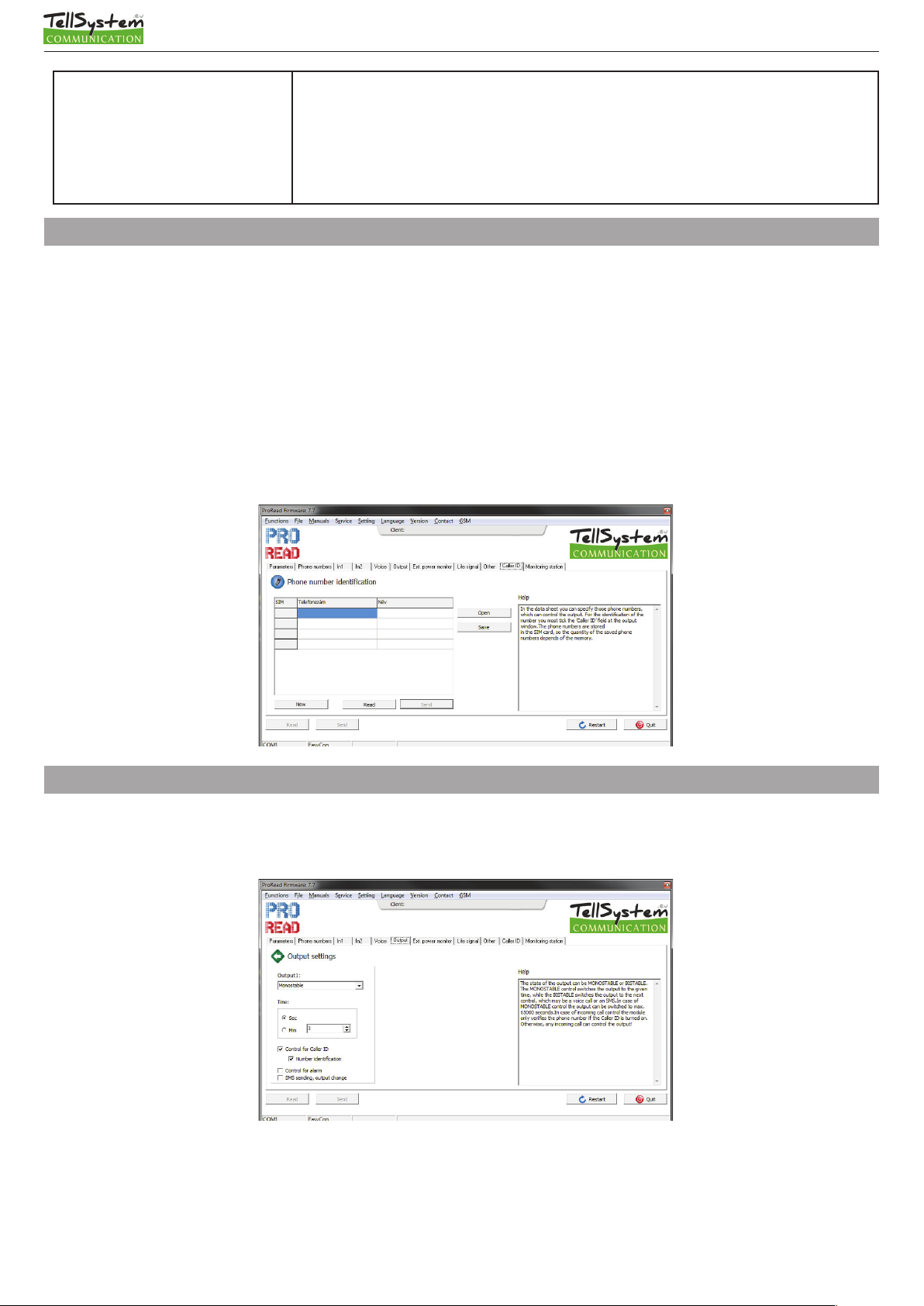
Output settings
Output modes can be set in the Output tab.
• MONOstable mode: output is controlled for the preset time, then releases (1-65000 seconds).
• BIstable (two-state) mode: changes state on every command and stays in that state indefinitely.
page 4. TellSystem Communication
Page 5

EasyCon GSM
tellsystem.eu
Input settings
Inputs can be used in different operation modes [In (e.g.:1;2)tab/Types of Input]:
• 24h normal: continuously monitors input, in case of alarm sends signals.
• On (e.g.:1;2) tab/Inverted Operation: in normal position input expects short-circuit, if function is checked in normal position it
expects cut.
• SMS/Voice call about restore: if checked, notification is received about input restore also. In case of SMS (Other/Restore) mes-
sage is sent.
• Siren sound: In case of VOICE call, emits a siren sound (20-30 seconds).
• Sending a voice message: In case of VOICE call, it plays recorded voice.
Attention! If neither siren sound, nor voice message is checked, GSM automatically disconnects line, and there is no sound! Siren
sound and voice message can be used together, in this case siren sounds shortly then voice message is played.
Power monitor
The device constantly monitors incoming voltage (12V, GND terminal block), if voltage goes below 10V (external battery low) it is
capable of sending alarm. Notification about restore can be requested.
page 5. TellSystem Communication
Page 6

EasyCon GSM
tellsystem.eu
Life signal
Settings can be made on Life Signal tab: it is recommended to request a test message every week or every second week to check
proper operation of device. Frequency (every 1-255 days) and time of message can be set. Only full hours of the clock can be set:
e.g. 12:00, 13:00, etc. You can also set how many days after setting you wish to receive the first message. Life signal can only be
requested as SMS, with a custom message.
SMS forward
Other tab/SMS Forward: with this function the module forwards every uninterpretable message to a preset phone number. This
is a useful function to receive the pre-paid SIM card balance message.
Description of voice calls
Every outgoing VOICE call needs to be confirmed by user. Answering the phone qualifies as confirmation, no code or pressing of
button is required. You do not need to listen to the siren sound/voice message, answering the phone means confirmation. Avoiding voicemail confirmation, your ringtone time needs to be set shorter than your voicemail pickup. This way the module disconnects the phone line before voicemail confirmation (Other tab/Ringtone Time). By default, if anyone answers the call, the alarm is
confirmed and no further numbers are called. If circular calling function is turned on, everyone has to confirm the call.
With the number of redials you can set how many outgoing calls the module can make in one alarm period. Unless for a good
reason do not set a value less than 50.
An 8 second message can be recorded for the following signals: inputs, power failure alarm.
You may record an identification message of less than 16 seconds. For practical reasons you may want to include the place of installation and name of facility in the message. This message is played before the voice message. Its use is not compulsory.
Order of voice messages: Siren sound + identification message + Alarm message
page 6. TellSystem Communication
Page 7

EasyCon GSM
tellsystem.eu
Description of SMS
For each input you may set a different SMS message and the phone numbers you wish to send them to. The SMS text message can
not be more than 32 characters long; use of special characters is not recommended.
Calendar of events
The module is capable of storing 16.000 events, which can be read out with the programming software. If you would like to use
this function, set the clock of the GSM module, because events will be time stamped accordingly.
Possible events: signals (input, power monitor), GSM status (GSM connected/disconnected), incoming calls with phone numbers.
The device stores signal strength and GSM status (connected/disconnected/roaming) for each event. You may prepare an access
identification and/or working hour management system by using the calling phone numbers.
Signal strength monitoring
The module constantly monitors signal strength, and saves the lowest signal strength data every hour. Signal strength data can be
read out using the programme, where it is displayed as a graph. When performing maintenance you can check for constant signal
strength. The module is capable of storing signal strength data for the last 20 years.
SMS programming
The basic functions of the device can be programmed via SMS. The SMS text message needs to start with the security code followed by the SMS command and parameter. One message can only contain one command. The default security code is 1234 (the
actual command is in bald type).
SMS command Description Parameter
1234codXXXX Security code change XXXX = new security code, alphanumeric
1234swtel1,tel2,..tel8 Change or delete phone numbers
to be notified
1234opar1,par2,tttt,kk Installation settings Par1,2(input)=ssssssssvvvvvvvv
1234k1 Activate output Control output 1
1234k1on In case of bistable output Switches on bistable output
1234k1of In case of bistable output Switches off bistable output
1234clkhhmm Clock settings hhmm=hours minutes e.g. 0509 5 o’clock 9 minutes
1234t Status enquiry Device sends notification about its actual status.
Tel1 = telephone number 1
Tel8 = telephone number 8
Tel = d, delete number
S= send SMS can be “1” or “0”
V = send VOICE message
These are the messages that belong to the phone numbers.
page 7. TellSystem Communication
Page 8

EasyCon GSM
Programming installation settings:
ssssssss = The eight “s” letters determine whether you wish to send SMS to the phone numbers to be notified. If “s”=1 the device
sends SMS; if 0 it does not. If you leave it blank, previous settings remain.
vvvvvvvv = The eight “v” letters determine whether you wish to send VOICE message to the phone numbers to be notified. If “s”=1
the device makes a voice call; if 0 it does not. If you leave it blank, previous settings remain.
tttt = types of the two inputs. “t” can be a value between 0 and 5, a letter “i” (= inverted) or “n” (= non-inverted) needs to be put
before the value. E.g.: i1 = normal inverted input
0 Input off
1 24 hour normal input
2 Not used
tellsystem.eu
If you put an “i” before the number, the input will be inverted.
kk = type of output. “k” = a value between 1 and 7.
(K) MONO/BI stable Alarm control Caller ID control
1 BI stable OFF OFF
2 MONO ON OFF
3 BI ON OFF
4 MONO OFF ON
5 BI OFF ON
6 MONO ON ON
7 BI ON ON
E.g.: Input1 sends SMS to 2nd and 3rd phone number, Input2 sends voice message to 1st phone number, input1 is 24 hour normal,
input2 is inverted normal. The output is monostable, controlled with alarm.
1234o0110000000000000,0000000010000000,,,,n1i1n0n0,22
page 8. TellSystem Communication
Page 9

EasyCon GSM
tellsystem.eu
Monitoring station
The module is capable of sending its signals in Contact ID format to a monitoring station through VOICE channel. Codes and zones
might be edited in the Monitoring Station tab. Here you can enter the customer code and 2 monitoring station phone numbers.
Monitoring station alerts can be used in parallel with other alarms (SMS, VOICE), so the device can notify both remote surveillance
and customer. The module first tries to call monitoring station (max. 8 redials) then sends SMS, and finally makes VOICE calls. You
may check the status of sending in Functions menu/Module Status in Error Codes/CID; in case of error you may also learn the reason for error. You can change your TX/RX levels; however, after modification module needs to be restarted.
When notifying monitoring station the use of high gain antenna is recommended, since perfect transmission requires suf-
ficient signal strength (above 60%).
Monitoring station signals: Input1, Input2, Power supply, Periodic life signal. Changeable customer code and changeable zone.
Software updates
You can easily update the module’s software and this way be notified of new functions and error corrections. It is always the programming software that contains the firmware, so make sure to download the latest version. Start Functions/Software Update
menu, then check the firmware version at the bottom. You may change your current version for an older one; however, it is not
recommended. If there is a newer version, press the programme update button, and the programme updates the module in two
steps (it takes about 3 minutes). In case of successful update the window closes automatically. If there is no such menu, or the
service is unavailable, update in service shops (old modules).
You may view the module’s software version in menu Functions/GSM Software Version.
page 9. TellSystem Communication
Page 10

EasyCon GSM
tellsystem.eu
Other commands
In the Functions/Monitor menu you may monitor and save GSM traffic. In case of defective operation, you should monitor error
and send it in email to our technical assistant who will of service.
In the Functions/Module Status menu you may check module status. Input/output states and module error code are shown in real
time. The status of Contact ID sending is shown in error code.
The Description/Circuit Diagram menu shows the circuit diagram of the module in use, helping installation.
In Basic Data menu you may enter data concerning the installation, these can be saved in File Operations/Save, because these data
are not stored in the module. Saving data for later use is recommended. The function does not save caller ID phone numbers and
recorded voices, only configuration settings.
The process of PC programming:
• after powering up the module, connect the programming cable
• if the name of the device shows click start
• in the telephone tab enter the phone numbers you wish to notify, then fill in the other tabs
• finally, transfer the configuration and save the settings by clicking the send button
• if you wish to use the caller ID function, enter the telephone numbers in the caller identification tab
• if you do not wish to use the factory default siren sound, upload your pre-recorded messages in the voices tab
• finally, it is recommended to save the configuration in File Operations, filling in the basic data.
Circuit diagram
Frequently asked questions and answers
• Caller identification does not work: Check with the service provider whether caller ID function is enabled in your module’s SIM
card. Check the caller ID function in the controller telephone. In the module’s settings “control with incoming call” needs to be
checked. Check if the phone numbers are stored on the SIM card.
• ACT LED remains red after alarm: Module cannot send message either because SIM card has run out of credit or incorrect
phone number has been entered. Check the SMS centre number of the module’s SIM card.
page 10. TellSystem Communication
Page 11

CE certificate
EasyCon GSM
tellsystem.eu
page 11. TellSystem Communication
 Loading...