

Page 1
Manual Of IP-VDSL VX-VEB165
Page 2

User manual of Modem
Class B
This Modem made for Home application is registered on EMI/EMC, can be used for
residential as well as out of residential Area
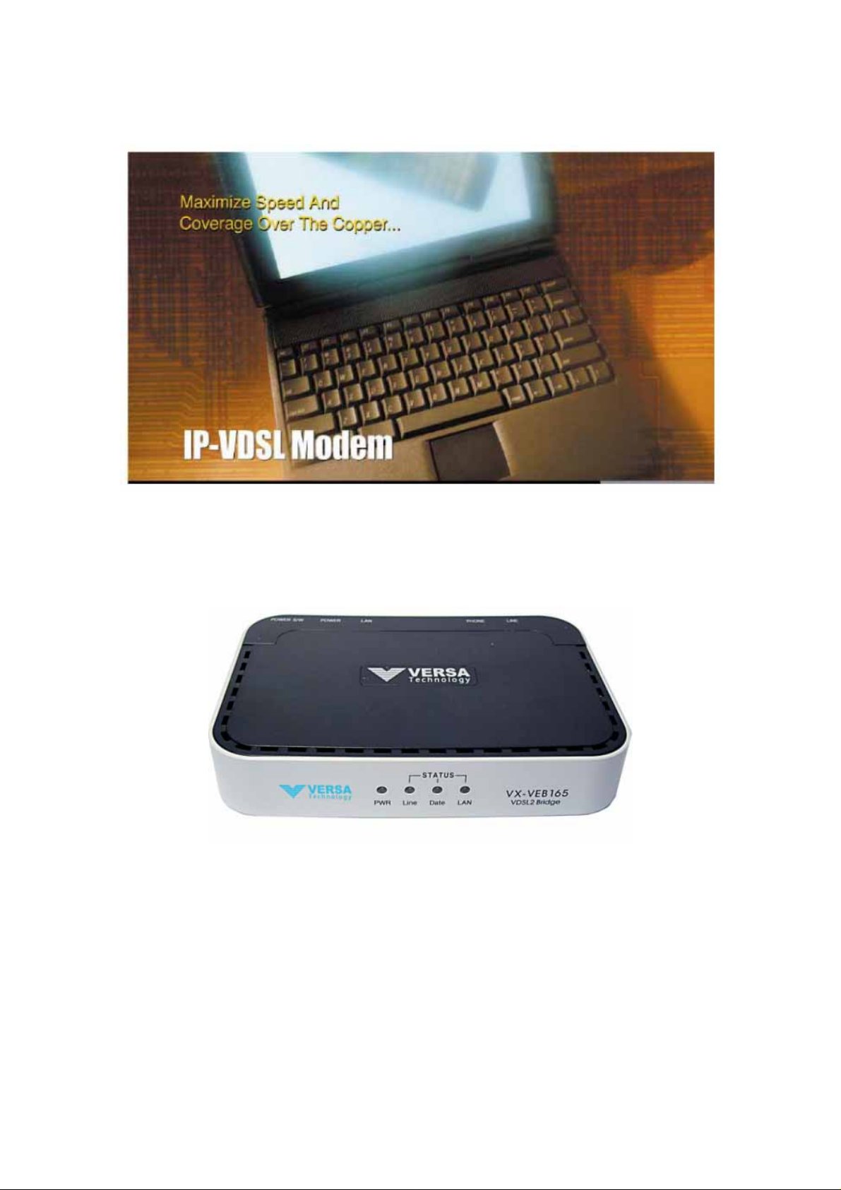
This Manual on IP-VDSL VX-VEB165 MODEM describes how to install
and operate it, your understanding and using for it is highly
recommended.
Page 3

User manual of Modem
Contents
1. Product Introduce
2. Packing contents confirmation of IP-VDSL VX-VEB165
3. Connect cables
4. System composition
5. Specification of IP-VDSL VX-VEB165
Page 4
User manual of Modem
1. Introductions
IP-VDSL VX-VEB165 is MODEM providing very high speed Data Service and
common Telephone Service to user through residential Telephone line.
IP-VDSL VX-VEB165 is MODEM providing various Multi-media service such as
high speed internet connection
Internet Broad Casting, Remote Diagnosis, Monitoring conference, VOD etc..
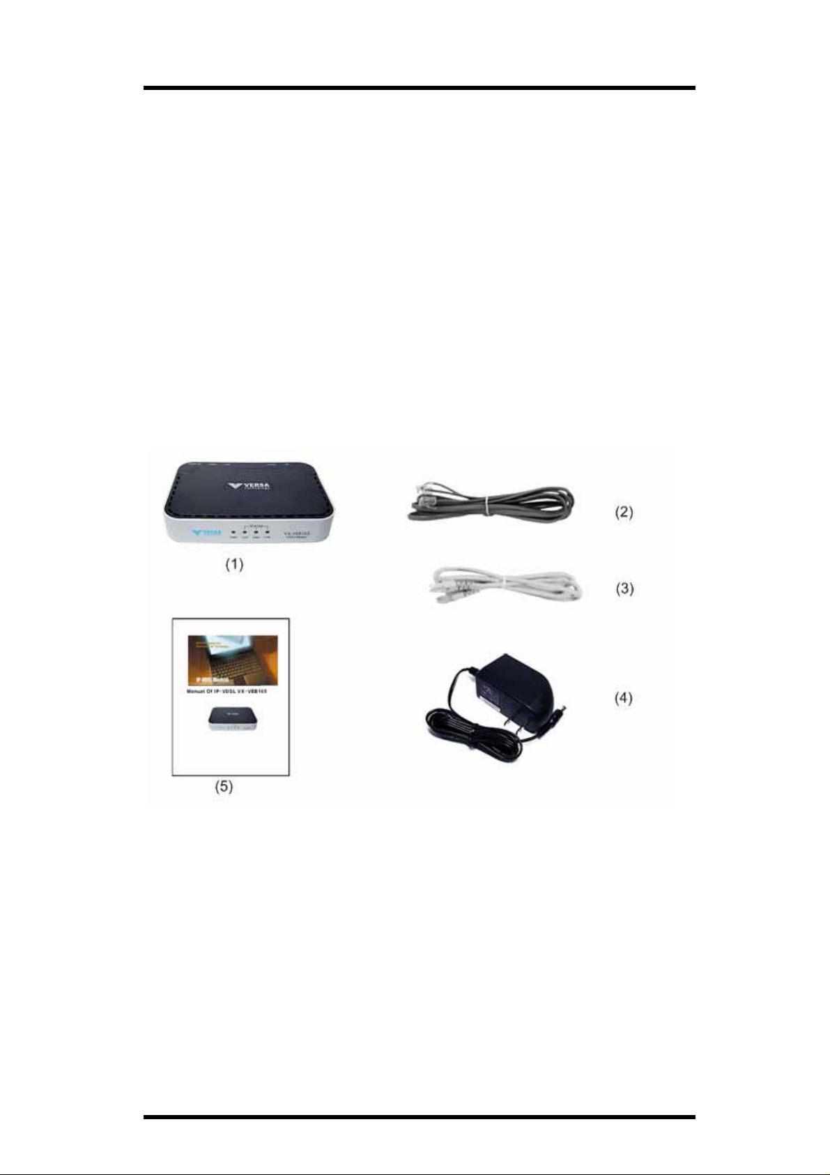
2. Accessories of IP-VDSL VX-VEB165
(1) VX-VEB165 modem
(2) (2) RJ-11 cable
(3) (3) RJ-45 cable
(4) (4) DC 5V/2A adaptor
(5) VX-VEB165 Manual
Page 5

User manual of Modem
3. Connect Cables
Caution : Confirmation of power switch off VX-VEB165 MODEM, Before
connecting the cables
VDSL Line Connection (VDSL Port)
Connecting the residential Telephone wire of using Telephone to
Telephone socket of wall and IP-VDSL Port
Telephone Connection(PHONE Port)
Connecting RJ-11 cable : Phone Cable (included Accessory ) to Phone
port on VX-VEB165 MODEM and Telephone
PC connection(LAN port)
Connecting Ethernet Cable : RJ-45 Cable(included Accessory) to LAN
Port on VX-VEB165 MODEM and LAN card on Computer
Power Adaptor connection(DC 5V 2A Port)
Connecting Power Adaptor Cable(included Accessory) to DC 5V 2A
Input Port on VX-VEB165 MODEM
RJ-11 Cable
VDSL Line
RJ-45 Cable
(To PC’s LAN port)
DC 5V/ 2A from Adaptor
Cable Connection of VX-VEB165
Page 6

4. System Composition
Front
User manual of Modem
Name LED color Ability
PWR Green Lighting on connecting to correct power
LINE Green Lighting on connecting VDSL LINK,
Blinking on sending and receiving data
DATA Green Lighting on connecting to VDSL Link,
Blinking on sending and receiving data
LAN Green Lighting on connecting to Ethernet Link,
Blinking on sending and receiving data
Page 7

Back
NAME Use Descriptions
User manual of Modem
LINE VDSL Line Port Sending and receiving the VDSL data and
connecting Telephone socket on the wall
PHONE Telephone
connection port
LAN Ethernet port Connecting to LAN card of the PC using the
DC 5V/2A Power input JACK Connecting Power Adaptor to MODEM
POWER S/W Power switch Providing Power to MODEM
Connecting to Telephone through the micro
filters
straight type LAN cable
Page 8

User manual of Modem
5. Specifications of IP-VDSL VX-VEB165
Items Specifications
Standard
Interface
VDSL
VDSL standards
ETSI VDSL standard
ITU ITU-T G.993.1
IEEE
IEEE 802.3 10BASE-TX
IEEE 802.3u 100BASE-TX
Ethernet Interface
10/100BASE-TX(IEEE 802.3 Auto-negotiation)
Connector : RJ-45
VDSL interface
Connector : RJ-11
POTS interface
Connector : RJ-11
Modulation
DMT
Transmission
Full-duplex, Frequency Division Multiplexing(FDD)
Data Rate
Symmetrical : 100/100Mbps(MAX rate)
Band Plan
Plan 998
PSD MASK
ETSI, ANSI, ITU-T(G.993.1) VDSL Standards
Upstream Power-Back-Off
Support Upstream Power-back-off
Loopback
Support remote and local loopback for network
connection test
CPE Configurations
Page 9

User manual of Modem
VDSL Automatic setting of line speed
Automatic setting(10/100BASE-TX Auto-negotiation) of
port parameter
Connector Two RJ-11 connector (LINE, PHONE)
ONE RJ-45 connector(LAN)
Power Input JACK (DC 5V 2A)
LED POWER, LINK, DATA, LAN
Environment Temperature : 0~50℃(in work), -40~70℃(in Keeping)
Humidity : 5~90%
Dimension
And Weight
Power Input : 100~240VAC, 50~60Hz, DC 5V/2A
Dimension :
Weight :
Electric Power gauge : 10 Watt(MAX)
Page 10

Certification o f Guarantee
Name of Product IP-VDSL MODEM
Name of Model IP-VDSL VX-VEB165
Serial Number
Purchase Date
Insurance Period 1 year
User manual of Modem
Customer
Name
Tel
Address
E-Mail
Regulations of compensation for user
Damaged MODEM shall be compensated under regulations of compensation
for user
Guarantee in detail
1. This product is made through strict quality control test process
2. 1 year warrantee shall be provided user without case of no #3
3. It shall be charged for providing technique and machine parts, in following
cases
Carelessness using
Natural disasters(fire, earthquake, flood, thunderbolt, etc)
Incorrect input power supply
Damaged by unconfirmed Devices.
Damaged by Repair and Modification by and unidentified A/S Engineer.
Address : 8
Geumchoen-gu, Seoul, 153-801, Korea
Homepage : www.tellion.com
th
FL, Leaders Tower, 60-15 Gasan-dong,
Page 11

CAUTION: Changes or modifications not expressly approved by the manufacturer
responsible for compliance could void the user’s authority to operate the equipment
WARNING
This device complies with part 15 of the FCC Rules. Operation is subject to the
following two conditions: (1) This device may not cause harmful interference, and (2)
this device must accept any interference received, including interference that may cause
undesired operation.
INFORMATION TO USER:
This equipment has been tested and found to comply with the limit of a Class B digital
device, pursuant to Part 15 of the FCC Rules. These limits are designed to provide
reasonable protection against harmful interference in a residential installation. This
equipment generates, uses and can radiate radio frequency energy and, if not installed
and used in accordance with the instructions, may cause harmful interference to radio
communications. However, there is no guarantee that interference will not occur in a
particular installation; if this equipment does cause harmful interference to radio or
television reception, which can be determined by turning the equipment off and on, the
user is encouraged to try to correct the interference by one or more of the following
measures:
1. Reorient / Relocate the receiving antenna.
2. Increase the separation between the equipment and receiver.
3. Connect the equipment into an outlet on a circuit difference from that to which
the receiver is connected.
4. Consult the dealer or an experienced radio/TV technician for help
Page 12

 Loading...