

Telldus PAN11-1B, PAN11-2B, PAN11-3B, PAN11-5B, PAN11-8B User Manual
1
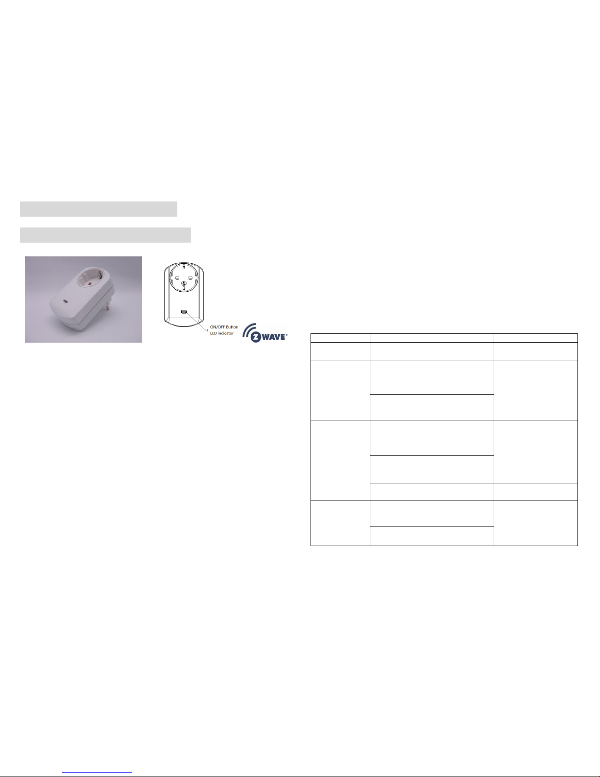
PAN11-1B/-2B/-3B/-5B/-8B
Smart energy plug in switch
P
This plug-in ON/OFF switch PAN11 is a security enabled wireless switch, based on
Z-Wave Plus technology. Z-Wave PlusTM enabled devices displaying the Z-Wave
PlusTM logo can also be used with it regardless of the manufacturer, and can also be
used in other manufacturer’s Z-WaveTM enabled networks. Remote On/Off control of
the connected load is possible with other manufacturer’s wireless Controller. Each
switch is designed to act as a repeater. Repeaters will re-transmit the RF signal to
ensure that the signal is received by its intended destination by routing the signal
around obstacles and radio dead spots. Because PAN11 supports Security Command
Class, it can learn with Secured controller. Its functionality and supported command
classes is identical when included as a secure and non-secure device.
This plug-in ON/OFF switch is able to detect instance wattage (3000W/CE/CN,
1500W/UL/TW/JP) and overload current (14.5A) of connected lights or appliances.
When detecting overload state, the Switch will be disabled and its On/Off button will
be lockout of which LED will flash quickly. However, unplug and re-connect the
switch will reset its overload condition to normal status.
Adding to Z-WaveTM Network
In the front casing, there is an On/Off button with LED indicator which is used to toggle
switch on and off or carry out inclusion, exclusion, reset or association. When first
power is applied, its LED flashes on and off alternately and repeatedly at 0.5 second
intervals. It implies that it has not been assigned a node ID and start auto inclusion.
Auto Inclusion
The function of auto inclusion will be executed as long as the switch does not have
Node ID and just plug the switch into a wall outlet.
Note: Auto inclusion timeout is 2 minute during which the node information of explorer
frame will be emitted once several seconds. Unlike “inclusion” function as shown in
the table below, the execution of auto inclusion is free from pressing the On/Off button
on the Switch.
The table below lists an operation summary of basic Z-Wave functions. Please refer to
the instructions for your Z-WaveTM Certificated Primary Controller to access the Setup
function, and to include/exclude/associate devices
Function Description Annotation
No node ID The Z-Wave Controller does not allocate
a node ID to the Switch.
LED 2-second on,
2-second off
Inclusion 1. Put your Z-Wave controller into
inclusion mode by following the
instructions provided by the
controller manufacturer.
2. Pressing On/Off button three times
within 2 seconds will enter inclusion
mode.
Exclusion 1. Put your Z-Wave controller into
exclusion mode by following the
instructions provided by the
controller manufacturer.
2. Pressing On/Off button three times
within 2 seconds will enter exclusion
mode.
Node ID has been excluded. LED 0.5s On, 0.5s Off
(Enter auto inclusion)
Reset 1. Pressing On/Off button three times
within 2 seconds will enter inclusion
mode.
Use this procedure only in
the event that the primary
controller is lost or
otherwise inoperable.
2. Within 1 second, press On/Off
button again for 5 seconds.

2
3. IDs are excluded. LED 0.5s On, 0.5s Off
(Enter auto inclusion)
Association 1. The PAN11 is an always listening
Z-Wave device, so associations may
be added or removed by a controller
at any time.
Or If your controller requires to have
the PAN11 send a 'node information
frame' or NIF for associations, then
pressing the On/Off button three
times within 2 seconds will cause
the PAN11 to send its NIF.
2. There are only one group for the
switch
Including a node ID allocated by Z-Wave Controller means inclusion. Excluding a node
ID allocated by Z-Wave Controller means exclusion.
Failed or success in including/excluding the node ID can be viewed from the Z-Wave
Controller.
LED Indication
To distinguish what mode the switch is in, view from the LED for identification.
State Type LED Indication
Normal Under normal operation, toggle On/Off button between On and Off.
When pressing On, LED lights up, whereas Off, LED is off.
No node ID Under normal operation, when the Switch has not been allocated a
node ID, the LED flashes on and off alternately at 2-second
intervals. By pressing On/Off button, it will stop flashing
temporarily.
Learning When PAN11 is in learning mode, LED flashes on and off
alternately and repeatedly at 0.5 second intervals.
Overload When overload state occurs, the Switch is disabled of which LED
flashes on and off alternately at 0.2 second intervals. Overload
state can be cleared by unplugging and reconnecting the Switch to
the wall outlet.
Choosing a Suitable Location
1. Do not locate the Switch facing direct sunlight, humid or dusty place.
2. The suitable ambient temperature for the Switch is 0°C~40°C.
3. Do not locate the Switch where exists combustible substances or any source of
heat, e.g. fires, radiators, boiler etc.
4.
After putting it into use, the body of Switch will become a little bit hot of which
phenomenon is normal.
Installation
1. Plug this On/Off Switch into a wall outlet near the load to be controlled.
2. Plug the load into the Switch. Make sure the load to be controlled cannot exceed
13A.
3. Press the button or switch on the load to the ON position.
4. To manually turn ON the Switch, press and release the On/Off button. The LED
will turn ON, and the load plugged into the Switch will also turn ON.
5. To manually turn OFF the Switch, simply press and release the On/Off button.
The LED will turn OFF and the load plugged into the Switch will also turn OFF.
Programming
1. Basic Command Class / Binary Switch Command Class
The Switch will respond to BASIC and BINARY commands that are part of the
Z-Wave system.
1-1 BASIC_GET / BINARY_SWITCH_GET
Upon receipt of the following commands from a Z-Wave Controller, the Switch will
report its On/Off state to the node asked.
Basic Get Command: [Command Class Basic, Basic Get]
Basic Report Command:
Report OFF: [Command Class Basic, Basic Report, Value = 0(0x00)]
Report ON:[Command Class Basic, Basic Report, Value = 255(0xFF)]
Binary Switch Get Command:[Command Class Switch Binary, Switch
Binary Get]
Binary Switch Report Command:
Report OFF:[Command Class Switch Binary, Switch Binary Report, Value
=0(0x00)]

3
Report ON:[Command Class Switch Binary, Switch Binary Report, Value =
255(0xFF)]
1-2 BASIC_SET / SWITCH_BINARY_SET
Upon receipt of the following commands from a Z-Wave Controller, the load
attached to the Switch will turn on or off.
[Command Class Basic, Basic Set, Value = 1~99,255(0xFF)]: the load
attached to the Switch turns on.
[Command Class Basic, Basic Set, Value = 0(0x00)]: the load attached to
the Switch turns off.
[Command Class Switch Binary, Switch Binary Set, Value = 1~99,
(255)0xFF]: the load attached to the Switch turns on.
[Command Class Switch Binary, Switch Binary Set, Value = 0(0x00)]: the
load attached to the Switch turns off.
2. Z-Wave’s Groups (Association Command Class Version 2)
The Switch can be set to send reports to associated Z-Wave devices. It supports
one association group with one node support for Grouping 1. For group 1, the Switch
will report its latest status to Z-Wave Controller.
Grouping 1 includes, SWITCH_BINARY_REPORT, METER_REPORT,
ALARM_REPORT.
2-1 Auto report to Grouping 1 (Maximum Node 1)
2-1-1 On/Off Event Report
When “on” or “off ” state has been changed, it will send Binary Switch Report to the
node of Grouping 1.
Binary Switch Report
ON:[Command Class Switch Binary, Switch Binary Report, Value
=255(0xFF)]
OFF:[Command Class Switch Binary, Switch Binary Report, Value
=0(0x00)]
2-1-2 Instant Power Consumption vary over 5% report
When the power consumption of load vary over 5%, it will send Meter report to the
nodes of Grouping 1.
Meter Report Command:
[Command Class Meter,,,,Meter Report,,,,Rate Type = 0x01,,,,Meter Type =
0x01,,,,Precision = 1,,,,Scale = 0x02,,,,Size = 4,,,,Meter Value(W) ]
2-1-3 Overload alarm report
When PAN11 detects the current is more than 14.5A, it will send Alarm Report to
Group 1 node.
The content of Alarm Report
Alarm report command:
[Command_Class_Alarm, Alarm_Report, Alarm Type = 0x08, Alarm Level =
0xFF]
2-2 Response to Meter Get Command
The Switch will report its (1) instant Power Consumption (Watt) or (2)
accumulated power consumption(KWH) or (3) AC load Voltage (V) or (4) AC load
current ( I ) (5) load power factor (PF) to Z-Wave Controller after receive the
Meter Get Command from Z-Wave Controller.
2-2-1 Instant Power Consumption (Watt) of Switch
When receiving Meter Get Command, it will report Meter Report Command to the
node.
Meter Get Command: [Command Class Meter, Meter Get, Scale =0x02(W)]
Meter Report Command:
[Command Class Meter,,,,Meter Report,,,,Rate Type = 0x01,,,,Meter Type =
0x01,,,,Precision = 1,,,,Scale = 0x02,,,,Size = 4,,,,Meter Value(W) ]
Example:
Meter Value 1 = 0x00 (W)
Meter Value 2 = 0x00 (W)
Meter Value 3 = 0x03 (W)
Meter Value 4 = 0xEA (W)
 Loading...