


Tellabs®8600 Managed Edge System
Tellabs
®
8609 Access Switch FP1.0
Tellabs
®
8611 Access Switch FP1.1
Interface Configuration Guide
76.8610-50149A
18.08.2011

Document Information
Revision History
Document No. Date
Description of Change s
76.8610-50149A 18.08.2011
First introduction.
© 2011 Tellabs. All rights reserved.
This Tellabs manual is owned by Tellabs or its licensors and protected by U.S. and international copyright laws, conventions and
treaties. Your right to use this manual is subject to limitations and restrictions imposed by applicable licenses and copyright laws.
Unauthorized reproduction, modification, distribution, display or other use of this manual may result in criminal and civil penalties.
The following trademarks and service marks are owned by Tellabs Operations, Inc. or its affiliates in the United States and/or
other countries: TELLABS
®
, TELLABS®logo, TELLABS and T symbol®, and T symbol®.
Any other company or product names may be trademarks of their respective companies.
The specifications and information regarding the products in this manual are subject to change without notice. All statements,
information, and recommendations in this manual are believed to be accurate but are presented without warranty of any kind,
express or implied. Users must take full responsibility for their application of any products.
Adobe
®
Reader®are registered trademarks of Adobe Systems Incorporated in the United States and/or other countries.
Tellabs®8600 Managed Edge System 76.8610-50149A
Tellabs
®
8609 Access Switch FP1.0 Tellabs®8611 Access Switch FP1.1 Interface Configuration Guide © 2011 Tellabs.
2

Document Information
Terms and Abbreviations
Term Explanation
AAL ATM Adaptation Layer
ACFC Address and Control Field Compression
AIS Alarm Indication Signal
ATM Asynchronous Transfer Mode
BE Best Effort
BER Bit Error Ratio
BFD Bidirectional Forwarding Detection
CAC Connection A dm ission Control
CBR Constant Bit Rate
CESoPSN Circuit Emulation Service over Packet Switched Network
CLI Command Line Interface
CRC Cyclic Redundancy Check
DEG Degraded
ESF Extended Super Frame
FCS Frame Check Sequence
FE Fast Ethernet
GE Gigabit Ethernet
HDLC High-Level Data Link Control
HM High speed Module
IEEE Institute of Electrical and E lectr
onics Engineer s
IETF Internet Engineering Task Force
IMA Inverse Mu ltiplex ing for ATM
IP Internet Protocol
IPCP IP Network Control Protocol of the PPP
IS-IS Intermediate System to Intermediate System ( In terior Gateway Protocol)
LAN Local Area Network
LCP Link Control Protocol
LLC Logical Link Control
LM Line Module
LOF Loss Of Frame
MAC Media A ccess Control
MC-MLPPP Multiclass M
LPPP
MGE Management GE
76.8610-50149A Tellabs®8600 Managed Edge System
© 2011 Tellabs. Tellabs
®
8609 Access Switch FP1.0 Tellabs®8611 Access Switch FP1.1 Interface Configuration Guide
3

Document Information
MLPPP Multilink PPP
MPLS Multiprotocol Label Sw itch ing. A switching m etho d that forwards IP trafficusinga
label.
MPLSCP MPLS Network Control Protocol of the PPP
MRU Maximum Receive Unit
MRRU Maximum Received Reconstructed Unit
MTU Maximum Transmission Unit
MuxCP Multiplexed Control Protocol
NCP Network Control Protocol
NE Network Element
NLPID Network Layer Protocol Identifier
NNI Network-to-Network Interface
NRT Non-Real Time
NTP Network Time Protocol
OAM Operations, Administration and Maintenance
OSINLCP OSI Netw ork Layer Control Protocol
P12s Framed 2.048 kbps according to G.704 and G.706
P12x Unframed 2.048 kbps according to G.703
PDH Plesiochronous Digital Hierarchy
PFC Protocol Field Compression
PFF Protocol Field Flag
PID Protocol ID
PLM Physical Line Module
PMD Physical Medium D epend ent
PPP Point-to-Point Protocol
PPPMux PPP Multiplexing
PPPMuxCP PPP Multiplex ed Control Protocol
PTM Packet Transfer Mode
PWE3 Pseudowire Emulation Edge to Edge
QoS Quality of Service
RAI Remote Alarm Indicator
RDI Remote Defect Indicator
RT Real Time
RTC Real Time Clock
RTT Round Trip Time
SAToP Structure-Agnostic Time Division Multiplexing over Packet
SF Super Frame
Tellabs®8600 Managed Edge System 76.8610-50149A
Tellabs
®
8609 Access Switch FP1.0 Tellabs®8611 Access Switch FP1.1 Interface Configuration Guide © 2011 Tellabs.
4

Document Information
SFP Small Form-factor Pluggable
SNAP Subnetwork Access Protocol
SRA Seamless Rate Adaptation
SSD Server Signal Degraded
SSF Server Signal Fail
TC Transmission Convergence layer
TDM Time Division Multiplexing
TLP Transmission Layer Port
UBR Unspecified Bit Rate
UDP User Datagram Protocol
UNI User Network Interface
VBR Variable Bit Rate
VC ATM Virtual Channel
VCC Virtual Channel Connection
VCCV Virtual Circuit Connectivity Verification
VCI Virtual Channel Identifier
VCL Virtual Channel Link
VLAN Virtual LAN
VP Virtual Path
VPC Virtual Path Connection
VPI Virtual Path Identifier
VPL Virtual Path Link
Vo I P Voi c e o v e r I P
XC Cross-Connection
76.8610-50149A Tellabs®8600 Managed Edge System
© 2011 Tellabs. Tellabs
®
8609 Access Switch FP1.0 Tellabs®8611 Access Switch FP1.1 Interface Configuration Guide
5

Tellabs®8600 Managed Edge System 76.8610-50149A
Tellabs
®
8609 Access Switch FP1.0 Tellabs®8611 Access Switch FP1.1 Interface Configuration Guide © 2011 Tellabs.
6

Table of Contents
Table of Contents
About This Manual ............................................................................................................10
Objectives....................................................................................................................................................................... 10
Audience......................................................................................................................................................................... 10
Related Documentation .................................................................................................................................................. 10
Interface Numbering Conventions ................................................................................................................................. 11
Document Conventions .................................................................................................................................................. 12
Documentation Feedback............................................................................................................................................... 12
1 Overview ......................................................................................................................13
1.1 ETSI and ANSI Mode ......................................................................................................................................... 13
2 Network Element Interfaces ....................................................................................... 14
2.1 Tellabs 8609 A ccess Switch ............................................................................................................................... 14
2.1.1 Overview ............................................................................................................................................. 14
2.1.2 Fixed Interfaces ................................................................................................................................... 14
2.1.3 Supported Line Modules ..................................................................................................................... 15
2.2 Tellabs 8611 Access Switch ............................................................................................................................... 15
2.2.1 Overview ............................................................................................................................................. 15
2.2.2 PLM Combination Rules ..................................................................................................................... 16
3 Physical Line Modules................................................................................................ 18
3.1 L ine Modules ....................................................................................................................................................... 18
3.1.1 8xchE1/chT1 LM ................................................................................................................................. 18
3.1.2 8x10/100BASE-TX LM ...................................................................................................................... 21
3.2 High Speed Modules ........................................................................................................................................... 22
3.2.1 4x100/1000BASE-X HM . ................................................................................................................... 22
3.2.2 4x10/100/1000BASE-TX HM............................................................................................................. 23
4 Management Port (MGMT) .......................................................................................... 25
5 Fault Management Operation and Configuration ..................................................... 26
76.8610-50149A Tellabs®8600 Managed Edge System
© 2011 Tellabs. Tellabs
®
8609 Access Switch FP1.0 Tellabs®8611 Access Switch FP1.1 Interface Configuration Guide
7

Table of Contents
5.1 TDM Fault Management ..................................................................................................................................... 26
5.1.1 Principles ............................................................................................................................................. 26
5.1.2 Fault Suppression ................................................................................................................................ 27
6 Performance Monitoring ............................................................................................. 28
6.1 T DM Performance Monitoring............................................................................................................................ 28
6.1.1 G.826 Performance Monitoring........................................................................................................... 28
6.1.2 GR-253/GR-820 Performance Monitoring.......................................................................................... 29
7 ANSI Loopback Operations ........................................................................................ 30
7.1 DS1 Loopback ..................................................................................................................................................... 30
7.1.1 Loopback Operation ........................................................................................................................... 30
7.1.2 Equipment Loopback Operation .......................................................................................................... 30
7.1.3 Invoking a Remote Loopback.............................................................................................................. 30
7.1.4 Remote Loopback Methods ................................................................................................................. 31
7.1.5 Loopback Example in SAToP Application ..........................................................................................31
7.1.6 Loopback Example in CESoPSN, and Multiservice Applications ...................................................... 32
8 References................................................................................................................... 34
9 Interface Configuration Examples............................................................................. 36
9.1 All Interfaces ....................................................................................................................................................... 36
9.1.1 Basic Configuration ............................................................................................................................. 37
9.1.2 Checking Interface Configuration Status and Basic Troubleshooting................................................. 38
9.2 Ethernet Basic Configuration............................................................................................................................... 41
9.3 Selecting Operation Mode ................................................................................................................................... 42
9.4 VLAN Management ............................................................................................................................................ 43
9.4.1 Acceptable Frame Filter ...................................................................................................................... 43
9.4.2 Create VLAN....................................................................................................................................... 43
9.4.3 Delete VLAN....................................................................................................................................... 43
9.5 8xchE1/chT1 LM................................................................................................................................................. 43
9.5.1 Starting Configuration ......................................................................................................................... 44
9.5.2 Configuring E1/T1 Physical Layer Interface....................................................................................... 45
9.5.3 Configuring P12s Layer for ATM........................................................................................................ 45
9.5.4 Configuring DS1 Layer for ATM ........................................................................................................ 46
9.5.5 Configuring P12s/DS1 for HDLC ....................................................................................................... 46
9.5.6 Configuring P12s/DS1 for PPP and MLPPP ....................................................................................... 47
9.5.7 Configuring ANSI Remote Loopbacks ............................................................................................... 52
9.5.8 Configuring Fault Monitoring and Reporting...................................................................................... 52
9.6 Management Port of SCM................................................................................................................................... 54
9.6.1 External Switch Operations ................................................................................................................. 54
9.6.2 Investigating MGMT Protection Status............................................................................................... 54
Tellabs®8600 Managed Edge System 76.8610-50149A
Tellabs
®
8609 Access Switch FP1.0 Tellabs®8611 Access Switch FP1.1 Interface Configuration Guide © 2011 Tellabs.
8

Table of Contents
Layer Descriptions............................................................................................................55
PDH Layers .................................................................................................................................................................... 55
Ethernet Layers .............................................................................................................................................................. 58
Port Protocols ................................................................................................................................................................. 59
Fault Management .......................................................................................................................................................... 74
76.8610-50149A Tellabs®8600 Managed Edge System
© 2011 Tellabs. Tellabs
®
8609 Access Switch FP1.0 Tellabs®8611 Access Switch FP1.1 Interface Configuration Guide
9

About This Manual
About This Manual
This chapter discusses the objectives and intended audience of this manual, Tella b s®8600
Managed Edge System Tellabs
®
8609 Access Switch and Tellabs®8611 Access Switch Interface
Configuration Guide and consists of the following sections:
• Objectives
• Audience
• Related Documentation
• Conventions
• Documentation Feedback
Objectives
This manual provides an overview of the Tellabs 8609 access switch and Tellabs 8611 access switch
interface functions and instructions on how to configure them using Command-Line Interface (CLI)
and ASCII textual commands with a router’s console or remote terminal (Telnet).
Audience
This manual is designed for administration personnel for configuring the Tellabs 8609 access switch
and Tellabs 8611 access switch interface functions with CLI. On the other hand, Tellabs
®
8000
Intelligent Network Manager provides access to equal functionality for administration personnel
with a graphical user interface.
It is assumed that you have a basic understanding of networks and network interfaces of different
technologies (ATM, PDH, PPP, Ethernet).
Related Documentation
The document numbering scheme consists of the document ID, indicated by numbers, and the
document revision, indicated by a letter. The references in the Related Documentation table below
are generic and include only the document ID. To make sure the references point to the latest
available document versions, please refer to the relevant product document program on the Tellabs
Portal by navigating to www.portal.tellabs.com > Product Documentation > Data Networking >
Tellabs 8600 Managed Edge System > Technical Documentation.
Tel l abs®8600 Managed Edge System
Hardware Installation Guide (76.8600-40039)
Provides guidance on mechanical installation,
grounding, powering, cabling and maintenance.
Tel l abs®8600 Managed Edge System FP1.0
Tel l abs
®
8609 Access Switch Reference
Manual (76.8610-40086)
Describes network element features: enclosure,
baseboard, interfaces and power supply modules.
Tellabs®8600 Managed Edge System 76.8610-50149A
Tellabs
®
8609 Access Switch FP1.0 Tellabs®8611 Access Switch FP1.1 Interface Configuration Guide © 2011 Tellabs.
10

About This Manual
Tel l abs®8600 Managed Edge System FP1.1
Tel l abs
®
8611 Access Switch Reference
Manual (76.8611-40087)
Describes network element features: enclosure,
baseboard, interfaces and power supply modules.
Tel l abs®8600 Managed Edge System ATM and
TDM Configuration Guide (76.8600–50110)
Provides an overview of Tellabs 8600 system ATM
and TDM functions and instructions on how to
configure them with CLI.
Tel l abs®8600 Managed Edge System CLI
Commands Manual (76.8600-50117)
Provides commands available to configure, monitor
and maintain Tellabs 8600 system products with CLI.
Tel l abs®8600 Managed Edge System
Equipment Management Configuration Guide
(76.8600-50118)
Provides an overview of Tellabs 8600 system HW
inventory, software management and CDC equipment
protection and instructions on how to configure them
with CLI.
Tel l abs®8600 Managed Edge System Ethernet
Configuration Guide (76.8600-50133)
Provides an overview of Tellabs 8600 system Ethernet
Applications and instructions on how to configure
them with CLI.
Tel l abs®8600 Managed Edge System
Fault Management Configuration Guide
(76.8600-50115)
Provides an overview of Tellabs 8600 system fault
management and instructions on how to configure it
with CLI.
Tel l abs®8600 Managed Edge System
IP Forwarding and Traffic Management
Configuration Guide (76.8600-50122)
Provides an overview of Tellabs 8600 system IP
forwarding and traffic management and instructions
on how to configure them with CLI.
Tel l abs®8600 Managed Edge System
MPLS Applications Configuration Guide
(76.8600-50123)
Provides an overview of Tellabs 8600 system MPLS
applications and instructions on how to configure
them with CLI.
Tel l abs®8600 Managed Edge System
Synchronization Configuration Guide
(76.8600-50114)
Provides an overview of Tellabs 8600 system
synchronization functions and instructions on how to
configure them with CLI.
Tel l abs®8600 Managed Edge System Test
and Measurement Configuration Guide
(76.8600-50124)
Provides an overview of Tellabs 8600 system testing
and measurement tools, connectivity verification and
instructions on how to configure them with CLI.
Tel l abs®8000 Intelligent Network Manager
Online Help
Provides instructions on how different operations
are performed with Tellabs 8000 intelligent network
manager. Describes also different parameters and
controls of the Tellabs 8000 intelligent network
manager dialogs and windows.
Note that the online help is not available on the portal
but it is incorporated in Tellabs 8000 intelligent
network manager.
Interface Numbering Conventions
To be able to follow more easily the feature descriptions and configuration examples given in th is
document, see also the Tellabs 8600 system interface numbering and related figures described in
Tellabs
®
8600 Managed Edge System CLI Commands M an
ual.
76.8610-50149A Tellabs®8600 Managed Edge System
© 2011 Tellabs. Tellabs
®
8609 Access Switch FP1.0 Tellabs®8611 Access Switch FP1.1 Interface Configuration Guide
11
About This Manual
Document Conventions
This is a note symbol. It emphasizes or supplements information in the document.
This is a caution symbol. It indicates that damage to e qu i pment is possible if the instructions
are not followed.
This is a warning symbol. It indicates that bodily injury is possible if the instructions are not
followed.
Documentation Feedback
Please contact us to suggest improvements or to report errors in our documentation:
Email: fi-documentation@tellabs.com
Fax: +358.9.4131.2430
Tellabs®8600 Managed Edge System 76.8610-50149A
Tellabs
®
8609 Access Switch FP1.0 Tellabs®8611 Access Switch FP1.1 Interface Configuration Guide © 2011 Tellabs.
12

1Overview
1Overview
This document gives an overview of the data service interface features supported by the Tellabs
8609 access switch and Tellabs 8611 access switch. The emphasis is on the software configuration
of the interfaces. The existing components, their features and installation instructions are presented
in the documents mentioned below.
Tellabs
®
8600 Managed Edge System Tellabs®8609 Access Switch Reference Manual and Tellabs
®
8600 Managed Edge System Tellabs®8611 Access Switch Reference Manual and Te l lab s®8600
Managed Edge System Hardware Installation Guide provide more inform a tion about the Network
Element (NE) including the supported Physical Line Modules (PLMs) and interfaces.
1.1 ETSI and ANSI Mode
The following table show s a summary of the supported modes:
NE
Module/Interface Type ETSI Mode ANSI Mode
Tellabs 8609 access switch
Tellabs 8611 access switch
8xchE1/chT1 P12s (E1)
DS1
76.8610-50149A Tellabs®8600 Managed Edge System
© 2011 Tellabs. Tellabs
®
8609 Access Switch FP1.0 Tellabs®8611 Access Switch FP1.1 Interface Configuration Guide
13

2 Network Elem ent Interface s
2 Network Element Interfaces
2.1 Tellabs 8609 Access Switch
2.1.1 Overview
The Tellabs 8609 access switch provides fixed Ethernet interfaces and two slots for the Line
Modules (LM). The NE supports numerous layer 2 and 3 protocols needed on the edge of the data
network to adapt various TDM, cell and packet based services to the IP/MPLS.
2.1.2 Fixed Interfaces
The Tellabs 8609 access switch supports up to 12 Ethernet interfaces, which are fixedtothe
chassis of the NE. There are two virtual modules, M0 and M1, with each comprising of 4 Ethernet
interfaces that support 100/1000BASE-X modes, in total there are 8 optical Gigabit Ethernet
interfaces available. An additional virtual module M2, comprises 4 Ethernet interfaces that support
10/100BASE-TX/1000BASE-T modes.
Ethernet Interfaces
The Ethernet interface functionality is implemented according to [IEEE 802.3]. At ingress, the
Ethernet interfaces accept frames with length or type encoding. The length encapsulated frames
support LLC/SNAP according to [IEEE 802.3]. At egress, the Ethernet interface always generates
frames with type encapsulation.
The NE supports VLAN tagging on Ethernet interfaces. All interfaces can accept VLAN
tagged, priority-tagged and untagged frames. The interface performs input filtering based on the
VLAN identifiers. The Ethernet ports can be configured to optionally discard all untagged and
priority-tagged frames. A VLAN identifier can be selected from the full VLAN identifier space
(1–4095 are valid values, 0 and 4096 are reserved).
The Ethernet interfaces support:
• Full duplex mode for 100/1000BASE-X interfaces
• Auto-negotiation function, which can be optionally disabled. In such cases a manually configured
operation mode (speed, half/full duplex) is used
• 256 VLANs per port
• Port based Ethernet PWE3 [RFC4448]
• Ethernet tagged mode PWE3 [RFC4448]
• Jumbo frames with the M TU values of up to 4470 bytes
• Port shaper, which limits the egress bandwidth of the Ethernet interface. The limit is user-configurable
Tellabs®8600 Managed Edge System 76.8610-50149A
Tellabs
®
8609 Access Switch FP1.0 Tellabs®8611 Access Switch FP1.1 Interface Configuration Guide © 2011 Tellabs.
14

2 Network Element Interfaces
• Synchronous Ethernet concept where the received line clock can be used as a reference to the
timing block and the Ethernet egress can be synchronized from the timing block
• Ethernet line and equipment loopbacks
• Support of IEEE802.1ag Ethernet OAM Fault Management
• Loopback (ping) function
• Continuity check function
• Linktrace function
• Support of ITU-T Y.1731 Performance Monitoring
• Frame loss ratio
•Framedelay
• Frame delay variation
• Support of IEEE1588 slave frequency synchronization
Ethernet Layer Configuration
The Ethernet interfaces support the following configuration options:
Configuration Option
Ethernet Physical Layer Configuration
Ethernet Layer Failure Reporting
2.1.3 Supported Line Modules
The Tellabs 8609 access switch provides two line module slots, M3 and M4, for the LMs. Any
combination of the supported LMs is allowed in the slots. The following are the LMs cur ren tly
supported:
• 8xchE1/chT1
• 8x10/100BASE-TX
2.2 Tellabs 8611 Access Switch
2.2.1 Overview
The Tellabs 8611 access switch provides a flexible modul
ar architecture, allowing the NE to
be equipped with various combination of Physical Line Module (PLM) types. The NE supports
numerous layer 2 and 3 protocols needed on th e edge of the data network to adapt various TDM, cell
and packet based services to the IP/MPLS. There are se
veral types of PLMs supported by the NE:
76.8610-50149A Tellabs®8600 Managed Edge System
© 2011 Tellabs. Tellabs
®
8609 Access Switch FP1.0 Tellabs®8611 Access Switch FP1.1 Interface Configuration Guide
15

2 Network Elem ent Interface s
• Line Modules (LM)
• 8xchE1/chT1
• 8x10/100BASE-TX
• High speed Modules (HM)
• 4x100/1000BASE-X
• 4x10/100/1000BASE-TX
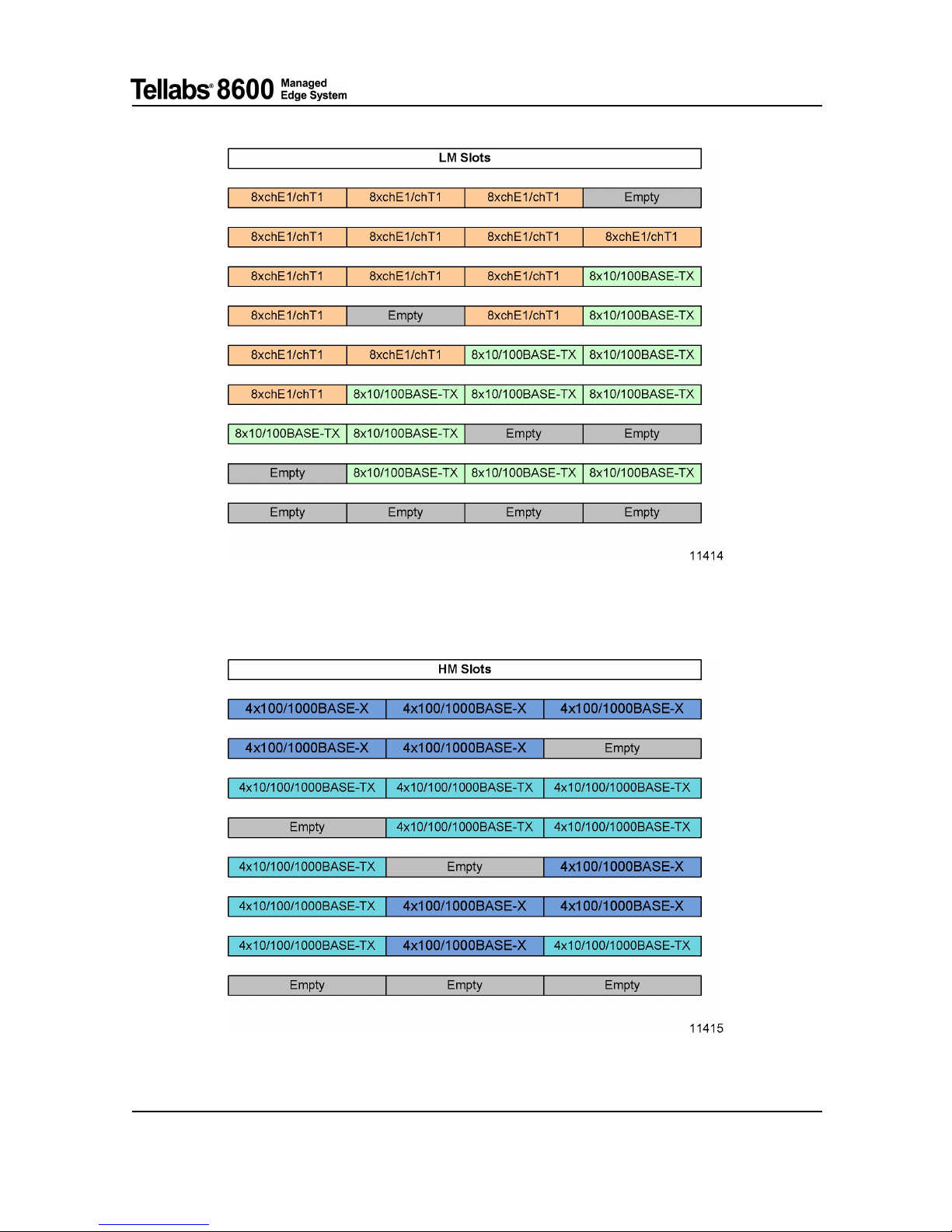
2.2.2 PLM Combination Rules
The Tellabs 8611 access switch provides four PLM slots, numbered M0 through M3 for the LMs
and three PLM slots, numbered M4 through M6, for the HMs. The NE architecture set some rules to
the PLMs equipping as following:
• There can be furnished up to four 8xchE1/chT1 LMs without any i nterference with the HMs.
• The 8x10/100BASE-TX LM, the 4x100/1000BASE-X and the 4x10/100/1000BASE-TX HMs
share r esources in the NE.
• A maxim um of three 8x10/100BASE-TX LMs are supported and they can be in any of the four
LM slots.
• Any combination of 4x100/1000BASE-X HMs and 4x10/100/1000BASE-TX HMs is allowed.
The following two figures illustrate possible combination of PLMs equipping in the Tellabs 8611
access switch:
Tellabs®8600 Managed Edge System 76.8610-50149A
Tellabs
®
8609 Access Switch FP1.0 Tellabs®8611 Access Switch FP1.1 Interface Configuration Guide © 2011 Tellabs.
16
2 Network Element Interfaces
Fig. 1 LM Combination
Fig. 2 HM Combination
76.8610-50149A Tellabs®8600 Managed Edge System
© 2011 Tellabs. Tellabs
®
8609 Access Switch FP1.0 Tellabs®8611 Access Switch FP1.1 Interface Configuration Guide
17

3 Physical Line Modules
3 Physical Line Modules
This section describes PLM types supported by the:
• Tellabs 8609 access s w itch
• Tellabs 8611 access switch
3.1 Line Modules
This section describes different media type of LMs supported by:
• Tellabs 8609 access s w itch
• Tellabs 8611 access switch
3.1.1 8xchE1/chT1 LM
Overview
The 8xchE1/chT1 LM provides 8 physical E1/T1 interfaces with HDB3/B8ZS line coding and
supports numerous layer 2 and 3 protocols needed on the edge of the data network to adapt various
TDM, cell and packet based services to the IP/MPLS.
• E1 mode
• Each interface supports unframed and framed P12s [G.704], [G.706] modes
• G.826 performance monitoring
• T1 mode
• Each interface supports DS1 framed [T1.403] and unframed modes
• Unframed, D4 Super Frame (SF) and Extended Super Frame (ESF) formats
• Remote line loopback
• GR-253/GR-820 performance monitoring
•E1andT1modes
• ATM/IMA payload, (ML)PPP, PPPmux, SAToP PWE3, CESoPSN PWE3, HDLC PWE3,
P12s/DS1 XC
• ATM/IMA group and MLPPP group across configuration LMs
• Non-intrusive P12s/DS1 frame monitoring for SAToP
• L1 line and equ ipm ent loops
• Adaptive timing from SAToP and CESoPS N PWE3 to physical E 1/DS1 interface
Tellabs®8600 Managed Edge System 76.8610-50149A
Tellabs
®
8609 Access Switch FP1.0 Tellabs®8611 Access Switch FP1.1 Interface Configuration Guide © 2011 Tellabs.
18
3 Physical Line Modules
NE and LM Type: Tellabs 8609 Access Switch, Tellabs 8611 Access Switch and 8xchE1/chT1
MS
TLP Type
Unframed Framed Nx64k (for ATM and
MLPPP N is fixed)
Service
IP
Routing
MPLS
Switching
PWE3
IP
Routing
MPLS
Switching
PWE3
cHDLC
—— ——— —
HDLC
——
X
——
X
FR
—— ——— —
(ML)PPP
XX
X (PPP
only)
XX
(PPP only)
ETHo(ML)PPP
—— ———
X
ATM
—— —
X
—
X
2M/1.5M TDM
——
X
—— —
Nx64 TDM
—— ———
X
E1/DS1 Interface
ATM Fe a t u res
The ATM configured tributary enables the NE to be connected via an SDH transport network to
another device using ATM interfaces. The interfaces support simultaneous ATM switching, ATM
PWE3 tunneling [RFC 4717] and IP routing functions on an ATM-circuit basis.
All tributaries and ATM circuits can be configured independently on each layer. The 8 xchE1/chT1
LM supports UNI and NN I interface types. As the NE supports a permanent type o f ATM circuits,
the UNI/NNI configuration parameter has an impact only to the available VPI range. The following
protocol encapsulations are available:
• Switching of VPCs between two ATM capable interface
• Tunneling VPCs using ATM PWE3 encapsulation to MPLS with N-to-1 and 1-to-1 modes
[RFC4717]
• Switching of VCCs between two ATM capable interface
• Tunneling VCCs using ATM PWE 3 encapsulation to MPLS with N-to-1, 1-to-1 and SDU modes
[RFC4717]
• Terminating IP over AAL5 circuits with LLC-S NAP encapsulation for routing
The LM supports native ATM traffic management both for switched circuits and PWE3-tunneled
circuits includ ing the following functions:
• Non-hierarchical VP & VC scheduling according [af-tm-0121.000]
• Non-hierarchical VP & VC shaping [af-tm-0121.000]
• CBR, rt-VBR, nrt-VBR, UBR+ and UBR service categories [af-tm-0121.000]
• Connection and Admission Control (CAC) for provisioned VPCs on ATM interface basis
•Configurable overbooking and equivalent bandwidth calculation
76.8610-50149A Tellabs®8600 Managed Edge System
© 2011 Tellabs. Tellabs
®
8609 Access Switch FP1.0 Tellabs®8611 Access Switch FP1.1 Interface Configuration Guide
19

3 Physical Line Modules
• ATM VP segment and end-to-end loopback testing
• Inverse multiplexing over ATM versions 1.0 and 1.1 with symmetrical mode according to [afphy-0086.000] and [af-phy-00 86.00 1]
HDLC Features
HDLC PWE3 tunneling enables t unn elin g of the PPP in a transparent way [RFC4618].
Unframed E1/T1 SAToP PWE3 Features
The TDM configured PDH interface enables the NE to provide transparent primary rate TD M circuit
emulation services over an M PLS network. The P12s/DS1 signal is encapsulated as unframed to a
TDM PWE3 circuit with SAToP encapsulation according to [RFC4553]. Frame alignment can be
optionally monitored.
Nx64k CESoPSN PWE3 Features
The TDM-configured PDH interface enables the NE to provide Nx64k TDM circuit emulation
services over an MPLS network. The P12s/DS1 signal is terminated an d desired Nx64k signals
(timeslot groups) are encapsulated to a TDM PWE3 circuit with CESoPSN e ncapsulation according
to [RFC5086].
PPP (MLPPP) Features
The PPP and Multilink PPP (MLPPP) interface enables the NE to be connected to another Tellabs
8600 NE or third party equipment using a single logical link having capacity of several P12s/DS1
[RFC1990]. Within MLPPP the following features are supported:
• PPP Mu ltiplex ing (PPPMux) [RFC3153], for more details refer to PPPMux Layer Configuration;
• MC-MLPPP [RFC2686], for more details refer to MC-MLPPP Layer Configuration;
The PPP link i s terminated and may carry IP traffic towards a customer router, or MPLS traffic
towards an M PLS core network. Both framed and unframed E1 and DS1 are supported.
The PPP/MLPPP interface supports also Ethernet over PPP and Ethernet over MLPPP encapsulation.
However only port mode Ethernet PWE3 is supported. For more Ethernet details please refer to
Tellabs
®
8600 Managed Edge System Ethernet Applications Configuration Guide.
P12x/1.5M TDM Cross-Connection Features
The TDM cross-connection support enables the NE to be used as a native P12x (unstructured
E1/DS1) TDM cross-connect device.
E1/DS1 Layer Configuration
The 8xchE1/chT1 LM supports the following configuration options:
Configuration Option
E1 Physical Layer Configuration
Tellabs®8600 Managed Edge System 76.8610-50149A
Tellabs
®
8609 Access Switch FP1.0 Tellabs®8611 Access Switch FP1.1 Interface Configuration Guide © 2011 Tellabs.
20

3 Physical Line Modules
Configuration Option
P12s Layer Configuration
DS1 Physical Layer Configuration
DS1 Layer Confi guration
ATM Interface (Transmission Convergence) Layer Configuration
ATM IMA Interface Configuration
HDLC Interface Layer Configuration
Unframed E1/T1 SAToP TDM PWE3 Layer Configuration
Nx64k CESoPSN TDM PWE3 Layer Configuration
PPP Layer Configuration
MLPPP Layer Configuration
Fault Management
TDM Performance Monitoring
GR-253/GR-820 Performance Monitoring
The 8xchE1 /chT1 LM supports GR-253/GR-820 performance monitoring for DS1 layers as
described in chapter 6.1.2 GR-253/GR-820 Performance Monitorin g .
G.826 Performance Monitoring
The 8xchE1/chT1 LM supports G.826 performance mon ito rin g for E1/P12s layers as described in
chapter 6.1.1 G.826 Performance Monitoring.
3.1.2 8x10/100BASE-TX LM
Overview
The 8-port Fast Ethernet LM supports eight 10/100BASE - TX. The Ethernet interface functionality
is implemented according to [IEEE 802.3]. At ingress, the Ethernet interfaces accept frames with
length or type encoding. The length encapsulated frames support LLC/SNAP according t o [IEEE
802.3]. At egress, the Etherne t interface always generates frames w ith type encapsulation.
The NE supports VLAN tagging on Ethernet interfaces. All interfaces can accept VLAN-tagged,
priority-tagged and untagged frames. Double tagged VLAN frames 802.1q-in-q are also su pported.
The interfaces perform input filtering based on the VLAN identifiers. The Ethernet ports can be
configured to op tionally discard all untagged and priority-tagged frames. A VLAN identifier can be
selected from the full VLAN identifier space (1–4095 are valid values, 0 and 4096 are reserved).
The 8x10/1 00B ASE-TX LM supports:
• 256 VLANs per port
• Port based Ethernet PWE3
• Ethernet tagged mode PWE3 [RFC4448]
76.8610-50149A Tellabs®8600 Managed Edge System
© 2011 Tellabs. Tellabs
®
8609 Access Switch FP1.0 Tellabs®8611 Access Switch FP1.1 Interface Configuration Guide
21

3 Physical Line Modules
• Auto-negotiation function, which can be optionally disabled. In such cases a manually configured
operation mode (speed, half/full duplex) is used
• Ethernet line and equipment loopbacks
• Synchronous Ethernet concept where the received line clock can be used as a reference to timing
block and the Ethern et egress can be synchronized to timing blo ck
• Support of IEEE802.1ag Ethernet OAM Fault Management
• Loopback (ping) function
• Continuity check function
• Linktrace function
• Support of ITU-T Y.1731 Performance Monitoring
• Frame loss ratio
•Framedelay
• Frame delay variation
Layer Configuration
The 8x10/100BASE-TX LM supports the following configuration options:
Configuration Option
Ethernet Physical Layer Configuration
Ethernet Layer Failure Reporting
3.2 High Speed Modules
The Tellabs 8611 access switch provides support for High speed Modules (H M) covered in this
section.
3.2.1 4x100/1000BASE-X HM
Overview
The 4-port (optical) Gigabit Ethernet HM supports 100/1000B A SE-X interfaces.
The Ethernet interface functionality is implemented accord
ing to [IEEE 802.3]. At ingress, the
Ethernet interfaces accept frames with length or type encoding. The length encapsulated frames
support LLC/SNAP according to [IEEE 802.3]. At egress, the Ethernet interface always generates
frames w ith type and length encoding.
The Tellabs 8600 system supports VLAN tagging on Ethernet interfaces. All interfaces can accept
VLAN-tagged, priority-tagged and untagged fram es. Double tagged VLAN frames 802.1q-in-q
are also supported. The interfaces perform input fil
tering based on the VLAN identifiers. The
Ethernet ports can be configu red to opt ion a lly discard all untagged and priority-tagged frames. A
VLAN identifier can be selected from the full VLAN identifier space (1–4095 are valid values, 0
and 4096 are reserved).
Tellabs®8600 Managed Edge System 76.8610-50149A
Tellabs
®
8609 Access Switch FP1.0 Tellabs®8611 Access Switch FP1.1 Interface Configuration Guide © 2011 Tellabs.
22

3 Physical Line Modules
The 4x100/100 0BASE-X HM supports:
• 256 VLANs per port
• Port based Ethernet PWE3
• Ethernet tagged mode PWE3 [RFC4448]
• Jumbo frames with the M TU values of up to 4470 bytes
• 100/1000BASE-X interface support full duplex mo de
• Port shaper, which limits the egress bandwidth of the Ethernet interface. The limit is user-configurable.
• Synchronous Ethernet concept where the Ethernet egress can be synchronized to Timing Module.
See Tellabs
®
8600 Managed Edge System Synchronization Configuration Guid e for more details
• Ethernet line and equipment loopbacks
• IEEE802.1ag Ethernet OAM Fault Management
• Loopback (ping) function
• Continuity check function
• Linktrace function
• ITU-T Y.1731 Performance Monitoring
• Frame loss ratio
•Framedelay
• Frame delay variation
Layer Configuration
The 4x100/1000BASE-X HM supp orts the following configuration options:
Configuration Option
Ethernet Physical Layer Configuration
Ethernet Layer Failure Reporting
Ethernet OAM
3.2.2 4x10/100/1000BASE-TX HM
Overview
The 4-port (electrical) Gigabit Ethernet HM supports 10/100BASE-TX/1000BASE-T interfaces.
The Ethernet interface functionality is implemented according to [IEEE 802.3]. At ingress, the
Ethernet interfaces accept frames with length or type encoding. The length encapsulated frames
support LLC/SNAP according to [IEEE 802.3]. At egress, the Ethernet interface always generates
frames w ith type and length encoding.
76.8610-50149A Tellabs®8600 Managed Edge System
© 2011 Tellabs. Tellabs
®
8609 Access Switch FP1.0 Tellabs®8611 Access Switch FP1.1 Interface Configuration Guide
23

3 Physical Line Modules
The Tellabs 8600 system supports VLAN tagging on Ethernet interfaces. All interfaces can accept
VLAN-tagged, priority-tagged and untagged fram es. Double tagged VLAN frames 802.1q-in-q
are also supported. The interfaces perform input filtering based on the VLAN identifiers. The
Ethernet ports can be configu red to opt ion a lly discard all untagged and priority-tagged frames. A
VLAN identifier can be selected from the full VLAN identifier space (1–4095 are valid values, 0
and 4096 are reserved).
The 4x10/10 0/1 000BASE-TX HM supports:
• 256 VLANs per port
• Port based Ethernet PWE3
• Ethernet tagged mode PWE3 [RFC4448]
• Jumbo frames with the M TU values of up to 4470 bytes
• Auto-negotiation function, which can be optionally disabled. In such cases a manually configured
operation mode (speed, half/full duplex) is used
• Port shaper, which limits the egress bandwidth of the Ethernet interface. The limit is user-configurable.
• Synchronous Ethernet concept where the Ethernet egress can be synchronized to Timing Module.
See Tellabs
®
8600 Managed Edge System Synchronization Configuration Guid e for more details
• Ethernet line and equipment loopbacks
• IEEE802.1ag Ethernet OAM Fault Management
• Loopback (ping) function
• Continuity check function
• Linktrace function
• ITU-T Y.1731 Performance Monitoring
• Frame loss ratio
•Framedelay
• Frame delay variation
Layer Configuration
The 4x10/100/1000BASE-TX HM supports the follo win g configuration option s:
Configuration Option
Ethernet Physical Layer Configuration
Ethernet Layer Failure Reporting
Ethernet OAM
Tellabs®8600 Managed Edge System 76.8610-50149A
Tellabs
®
8609 Access Switch FP1.0 Tellabs®8611 Access Switch FP1.1 Interface Configuration Guide © 2011 Tellabs.
24

4 Management Port (MGMT)
4 Management Port (MGMT)
The Tellabs 8611 access switch provides a 10/100BASE-TX/1000BASE-T port dedicated for
management com munication (CLI or Tellabs 8000 intelligent network manager). There is one
MGMT port on each SCM of the Tellabs 8611 access switch. From configuration and functionality
point of view, the MGMT port is as any other Ethernet port of the Tellabs 8600 system . In addition
to the local management access, the M GMT port provides access to the network for the management
communication traffic.
The Tellabs 8611 access switch can have two SCMs for equipment protection purposes. Each SCM
has its own MGMT port. The MGMT port is automatically protected if the SCM is protected. The
MGMT port protection mechanism of the Tellabs 8600 system resembles the MSP1+1/ APS1+1
protection scheme used for STM-N POS interfaces. The protected MGMT port shares the same
configuration except for the MAC address that is unique in both sides. Status information, fault
reports and counters are gathered separately for both MGMT ports. Depending on the line status and
the equipment status of the SCMs, one of the two MGMT ports is active passing traffic through,
while the other MGMT port is passive. The passive MGMT port drops traffic at ingress direction.
76.8610-50149A Tellabs®8600 Managed Edge System
© 2011 Tellabs. Tellabs
®
8609 Access Switch FP1.0 Tellabs®8611 Access Switch FP1.1 Interface Configuration Guide
25

5 Fault Management Operation and Configuration
5 Fault Management Operation and
Configuration
5.1 TDM Fault Management
5.1.1 Principles
The fault management processing (f1, f2, f3 and f4 filter) of TDM layers is done according to
[G.806] and [ETS 300 417-7-1].
Defect filter f1, consequent action filter f2 and fault cause filter f3 are components of the fault
management process located within atomic functions (e.g. a trail termination point). These filters are
specified per atomic function and the time constants are fixed. Defect filter f1 integrates anom alies
into defects by performing a persistency check.
Consequent action filter f2 controls consequent actions (for instance AIS, RDI or SSF) that are
generated by an atomic function due to a detected defect.
A fault can cause multiple defect detectors to be activated. The activated defects are correlated
by a fault cause filterf3toobtainthefaultcause(correlated defect). The fault cause filter can
also suppress the fault according to management information. The parameters t hat are used for
suppression are atomic function specific (for example, AISreported, RDIreported, LOCreported).
Suppression of a fault has an impact only on the emitting of a particular fault, it do e s not suppress
the fault from th e correlation processes for the upper layer alarms. The f2 and f3 filters are only
applied to TDM layer (layer L1) defects by the Tellabs 8600 NE.
Failure filter f4 integrates fault cause failures (detected faults) b y performing a persistency check on
the fault before it declares the fault cause a failure [ETS 300 417-7-1]. A fault persistency filter is
used in order to red uce failures that are reported to the management system. A TDM transmission
failure is declared if the fault cause continuously persists for approximately 2.5 ± 0.5 seconds. The
failure is cleared if the fault cause is continuously absent for approximately 10 ± 0.5 seconds, the
exception is DS1 AIS which has a 15 seconds clearing time.
Tellabs®8600 Managed Edge System 76.8610-50149A
Tellabs
®
8609 Access Switch FP1.0 Tellabs®8611 Access Switch FP1.1 Interface Configuration Guide © 2011 Tellabs.
26

5 Fault Management Operation and Configuration
Fig. 3 Generic Fa ult Filtering in Tellabs 8600 NE
5.1.2 Fault Suppressio n
In the Tellabs 8600 system AIS, RDI and SSF faults are suppressed by default. This is based on the
principles that in a homogenous Tellabs 8600 NE a network failure is reported only once by the NE
which detects the primary reason of the failure. E.g. in the case of a received AIS signal the fault is
not reported by default because the root cause of the fault is not detected by the particular NE.
Typically the AIS reporting should be activated within the boundaries of the network areas managed
by different management systems or network operators.
76.8610-50149A Tellabs®8600 Managed Edge System
© 2011 Tellabs. Tellabs
®
8609 Access Switch FP1.0 Tellabs®8611 Access Switch FP1.1 Interface Configuration Guide
27

6 Performance M onitoring
6 Performance Monitoring
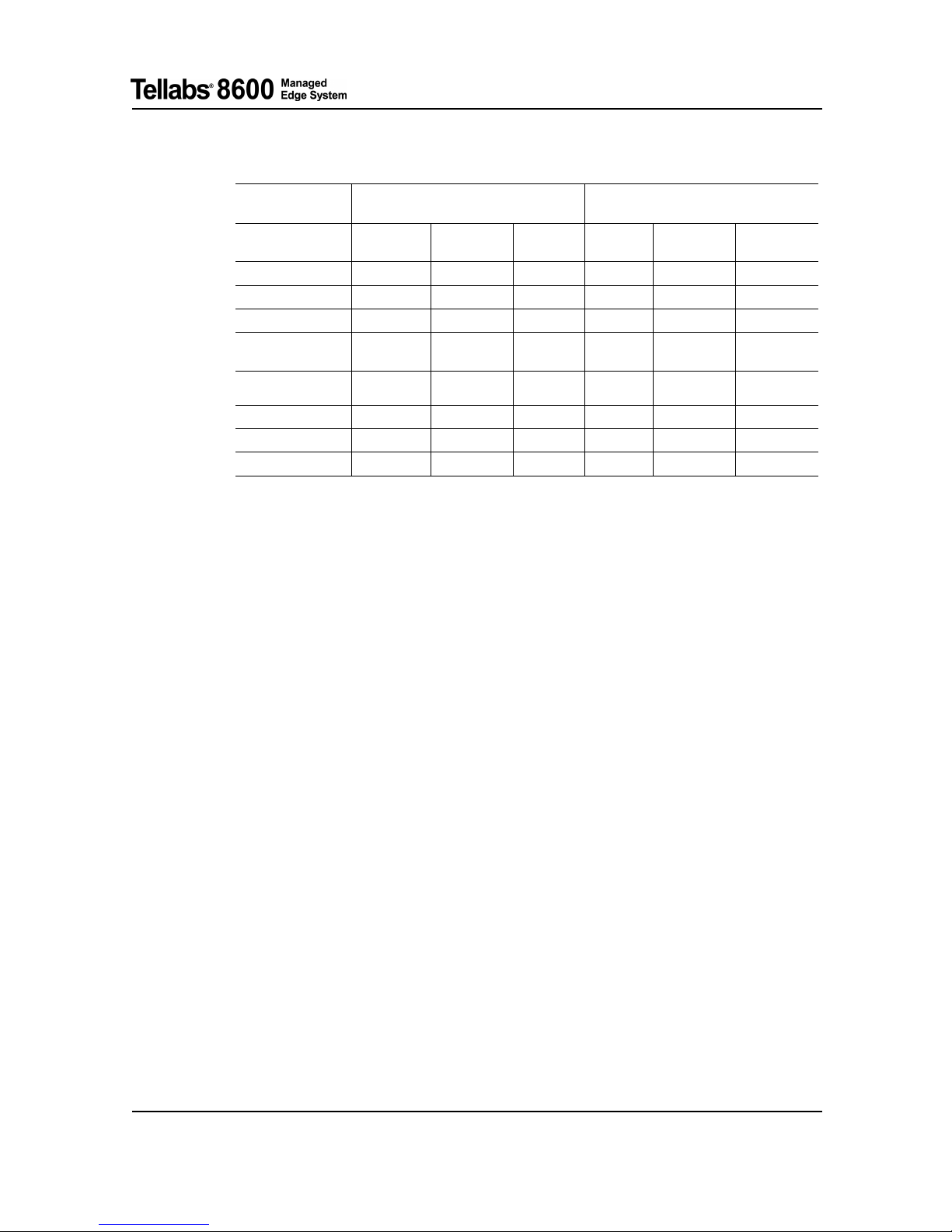
6.1 TDM Performance Monitoring
The following table shows the performance monitoring (G.826 and GR-253/GR-820) supported for
each TDM interface.
NE
Module/Interface
Typ e
ETSI Mode ANSI Mode
Tellabs 8609 access
switch
Tellabs 8611 access
switch
8xchE1/chT1
G.826
GR-253/GR-820
6.1.1 G.826 Performance Monitoring
The TDM interface can report 15-min and 24-hour current statistics and 15-minute and 24-hour
history statistics for the primitives as indicated in the following table. Both near-end and far-end
performance monitoring is supported. The unavailable seconds are counted separately for the
near-end and far-end. The NE stores 1 history 24-hour record and 31 15-minute history records
for each supported primitive. Monitoring is according [G.826].
PDH Near -E nd Performance Primitives
Primitive
Name PDH layers
E1 PHY P12s
neCv
Code Violations
XX
neSefs Severely Errored Framing Seconds
—
X
neEs
Errored Seconds
XX
neSes
Severely Errored Seconds
XX
neBbe Background block error Seconds
—
X
neUas
Unavailable Seconds
—
X
PDH Far-End Performance Primitives
Primitive
Name PDH layer
E1 PHY P12s
Tellabs®8600 Managed Edge System 76.8610-50149A
Tellabs
®
8609 Access Switch FP1.0 Tellabs®8611 Access Switch FP1.1 Interface Configuration Guide © 2011 Tellabs.
28

6 Performance Monitoring
feCv Code Violations
—
X
feEs Errored Seconds
—
X
feSes Severely Errored Seconds
—
X
feBbe Background block error Seconds
—
X
feUas Unavailable Seconds
—
X
6.1.2 GR-253/GR-820 Performance Monitoring
The TDM interface can report 15-min and 24-hour current statistics and 15-minute and 24-hour
history statistics for the primitives as indicated in the following table. Both near-end and far-e
nd
performance monitoring is supported. The unavailable seconds are counted separately for the
near-end and far-end. The NE stores 1 history 24-hour record and 31 15-minute history records
for each supported primitive.
For detailed DS1 performance monitoring fu nctionality [GR-253] refers to [GR-820]. The DS1
far-end information i s supported only in ESF mode which supports far-end defect reporting.
PDH/DS1 Near -E nd Performance Primitives
Primitive
Name PDH layer
DS1 Line DS1 Path
aisS AIS seconds
—
X
neCv
Code Violations
XX
neSefs Severely Errored Framing Seconds
—
X
neEs
Errored Seconds
XX
neSes
Severely Errored Seconds
XX
neUas
Unavailable Seconds
—
X
neFc
Failure Count
——
neLsS
Loss of Seconds
X
—
PDH/DS1 Far-End Performance Primitives
Primitive
Name PDH
DS1 Line Layer DS1 Path Layer
feCv Code Violations
—
X
feSefS Severely Errored Framing Seconds
—
X
feEs Errored Seconds
—
X
feSes Severely Errored Seconds
—
X
feUas Unavailable Seconds
—
X
feFc Failure Count
——
76.8610-50149A Tellabs®8600 Managed Edge System
© 2011 Tellabs. Tellabs
®
8609 Access Switch FP1.0 Tellabs®8611 Access Switch FP1.1 Interface Configuration Guide
29

7 ANSI Loopback Operations
7 ANSI Loopback Operations
The DS1 interface has some additional features compared to E1/P12s loopbacks and therefore the
whole DS1 loopback functionality is described in this section. This section applies to all interfaces
where the DS1 layer is available and the DS1 remote loopback functionality is supported. The
Tellabs 8600 system supports both inband and bit-patterned remote loopback commands according
to [T1.403] and [GR-312]. The remote loopback operation is configurable per DS1 interface and it
is enabled by default.
7.1 DS1 Loopback
7.1.1 Loopback Operation
The line loopback loops the received DS1 signal from DS1 line back to the line. The line loopback
can be controlled by local configuration using CLI or Tellabs 8000 intelligent network manager,
or remotely by responding to a remote loopback request commands received from the line side of
the DS1 interface. Line loopback is supported when the DS1 is terminated and also when the DS1
signal is transparently connected to SAToP PWE3. Both the local line loopback setting and the
remote command received from the DS1 line side control the same physical loop entity and the
latest action is in force. Analogously the loopback activated by both methods is released after the
loop timeout timer expires.
7.1.2 Equipment Loopback Operation
The equipment loopback loops the transmitted DS1 signal from DS1 line back to the equipment.
The equipment loopback is typically controlled by local configuration using CLI or Tellabs 8000
intelligent network manager. Both the local equipment loopback setting and remote comm and
received from the DS1 equipment side controls the same physical equipment loop entity and
the latest action is in force. In the SAToP service the remote loopback request can be received
from the equipment side of the DS1 interface over the SAToP PW E 3. In this case the equipment
loopback is performed. Analogously the l oop activated by both the methods is released after the
loop timeout timer expires.
7.1.3 Invoking a Remote Loopback
The operator can invoke a remote loopback by generating a remote loopback command. In the
Tellabs 8600 system it is possible to generate the commands only to the line direction of the DS1
interface. The remote loopback request does not contain any dedicated information about the
line/equipment loop selection. It is up to the receiver to decide which one of the loops is activated
on the basis of the direction where the request is received.
Tellabs®8600 Managed Edge System 76.8610-50149A
Tellabs
®
8609 Access Switch FP1.0 Tellabs®8611 Access Switch FP1.1 Interface Configuration Guide © 2011 Tellabs.
30

7 ANSI Loopback Operati ons
7.1.4 Remote Loopback Methods
The Tellabs 8600 system supports inband and bit-patterned methods with a wide set of
activation/deactivation codes as shown in the table below.
Method
CLI Activation Codes Deactivation Codes
Inband
csu
fac1
fac2
fac3
1 in 5, 00001 (T1.403)
2 in 4, 0011
2 in 5, 00011 ( GR-312)
1 in 6, 000001
1 in 3, 001, (T1.403)
3in4,0111
3 in 5, 00111, (GR-312)
1in3,001
Bitpatterned
ansi
bellcore
0 000111 0 11111111 (T1.403)
0 001001 0 1111 1111 (GR-312)
0 010010 0 1111 1111 (T1.403)
0 011100 0 111 11111 (T1.403)
0 010010 0 1111 1111 (GR-312)
Inband Method
The inband m ethod is available both in the terminated framed DS1 interface and unframed
(SAToP) DS1 interface. When the remote loopback is invoked, the interface sends the configured
activation/deactivation codes among the user data for a five-second period. If the far-end is capable
of detecting the codes, it performs the loop. The request causes a five-second break to the user
traffic. The Tellabs 8600 system monitors only one activation/deactivation code pair at the time in a
particular DS1 interface and therefore the code pair is configurable. The default code is 1-in-5/1-in-3.
If the interface is in Framed m ode (SF or ESF), it generates framed inband commands and, when
the interface is in Unframed mode (connected to SAToP PWE3), it generates unframed inband
commands. The DS1 interface always monitors both framed and unframed inband commands.
Bit-Patterned Method
The bit-patterned meth od is available only in ESF mode and only in the en d points of the DS1 path.
The commands are carried over th e facility data link and are available only in ESF mode. When the
remote loopback is invoked, the interface sends the activation/deactivation code 10 times t o the
facility data link. If the far-end is capable of detecting the codes, it performs the loop. The Tellabs
8600 system m onitors all the activation/deactivation codes shown in the table above at the time in a
particular DS1 interface without any configuration.
7.1.5 Loopback Example in SAToP Application
• Examples a) and b) in the figure below show CLI or Tellabs 8000 intelligent network manager
activated line and equipment loopback operations.
• Example c) in the figure below shows a remote loopback over the whole DS1 path. The Tellabs
8600 system is transparent for the request. The transparency can be achieved by disabling the
remote loopback function in the Tellabs 8600 system or using bit-patterned com man ds which
are carried over the facility data link or using inband commands when intermediate elements
(Monitor= A/B) and terminating elements (Monitor=C) use different inband codes.
76.8610-50149A Tellabs®8600 Managed Edge System
© 2011 Tellabs. Tellabs
®
8609 Access Switch FP1.0 Tellabs®8611 Access Switch FP1.1 Interface Configuration Guide
31

7 ANSI Loopback Operations
• Example d) in the figure below shows how a line loopback is activated remotely. The DS1 interfaces in the Tellabs 8600 NEs are in unframed modes and therefore only inband commands can
be sent and received. However, both unframed and framed inband commands are available.
• Example e) in th e figure below shows how an equipment loopback is activated remotely. The D S1
interfaces in the Tellabs 8600 NEs are in unframed modes and therefore only inband commands
can be sent and received. However, both unframed and framed inband commands are available.
Fig. 4 DS1 Loops in the Case of DS1 SAToP PWE3 Service
7.1.6 Loopback Example in CESoPSN, and Multiservice Applications
• Examples a) and b) in the figure below show CLI or Tellabs 8000 intelligent network manager
activated line and equipment loopback operations.
• Example c) in the figure below shows how an equipment loopback is activated remotely. Both
inband and bit-oriented commands can be used.
Tellabs®8600 Managed Edge System 76.8610-50149A
Tellabs
®
8609 Access Switch FP1.0 Tellabs®8611 Access Switch FP1.1 Interface Configuration Guide © 2011 Tellabs.
32

7 ANSI Loopback Operati ons
Fig. 5 DS1 Loops in the Case of DS1 Multiservice Interface and DS1 CESoPSN PWE3 Service
76.8610-50149A Tellabs®8600 Managed Edge System
© 2011 Tellabs. Tellabs
®
8609 Access Switch FP1.0 Tellabs®8611 Access Switch FP1.1 Interface Configuration Guide
33

8 References
8 References
[af-arch-0193.000] af-arch-0193.000 (2002-11), ATM User-Network Interwork Interface
(UNI) Specification Version 4.1
[af-phy-0054.000] af-phy-0054.000 (1996-01), DS3 Physical Layer Interface Specification
[af-phy-0086.000] af-phy-0086.000 (1997-07), Inverse multiplexing for ATM (IMA)
specification version 1.0
[af-phy-0086.001] af-phy-0086.001 (1999-09), Inverse multiplexing for ATM (IMA)
specification version 1.1
[af-tm-0121.000] af-tm-0121.000 (1999-03), Traffic management specification version 4.1
[af-uni-0010.002 ] af-uni-0010.002 (1994–09), ATM User-Network Interface Specification
Ver s i on 3. 1
[ETS 300 417-7-1]
ETSI EN 300 417-7-1 V1.1.1 (2000-10); Transmission and Multiplexing
(TM); Generic requirements of transport functionality of equipment;
Part 7-1: Equipment management and auxiliary layer functions
[G.704]
ITU-T Recommendation G.704 (1998-10), Synchronous frame
structures used at 1544, 6312, 2048, 8448 and 44 736 Kbps hierarchical
levels
[G.705]
ITU-T Recommendation G.705 (2000-10), Characteristics of
plesiochronous digital hierarchy (PDH) equipment functional blocks
[G.781]
ITU-T Recommendation G.781 (1999-07), Synchronization layer
functions
[G.806]
ITU-T Recommendation G.806 (2006-03), Characteristics of trans
port
equipment – Description methodology and generic functionality
[G.813]
ITU-T Recommendation G.813 (2003-03), Timing characteristics of
SDH equipment slave clocks (SEC)
[G.826]
ITU-T Recommendation G.826 (2002–12) End-to-end error performance
parameters and objectives for international, constant bit-rate digital paths
and connectionsTypes and characteristics of SDH network protection
architectures
[GR-253]
Telecordia, GR-253 (2005), Issue 4 – Synchronous o
ptical network
transport systems: common generic criteria
[GR-312]
Telecordia, GR-312 (2003-10), Functional Criteria for the DS1 Interface
Connector
[GR-499]
Telecordia, GR-499 (2004-09), Transport Systems Generic Requirements
(TSGR): Common Requirements
[GR-820]
Telecordia, GR-820–CORE (1997), Issue 2 – Ge
neric Digital
Transmission Surveillance
[I.361]
ITU-T Recommendation I.361 (1999-02), B-ISDN ATM layer
specification
[I.371]
ITU-T Recommendation I.371 (2000-03), Traffic control and congestion
control in B -ISD N
[I.432.1]
ITU-T Recommendation I.432.1 (1999-02
), B-ISDN user-network
interface – Physical layer specification: General characteristics
Tellabs®8600 Managed Edge System 76.8610-50149A
Tellabs
®
8609 Access Switch FP1.0 Tellabs®8611 Access Switch FP1.1 Interface Configuration Guide © 2011 Tellabs.
34

8 References
[I.432.2]
B-ISDN user-network interface (1999-02), Physical layer specification:
155 520 Kbps and 622 080 Kbps operation
[I.432.3]
B-ISDN user-network interface (1999-02), Physical layer specification:
1544 Kbps and 2048 Kbps operation
[I.732]
ITU-T Recommendation I.732 (2000-10), Functional characteristics
of ATM equipment
[IEEE 802.3]
IEEE Std 802.3, 2002 Edition – Local and m etropolitan area networks
– Specific Requirements – Part 3: Carrier sense multiple access with
collision detection (CSMA/CD) access method and physical layer
specifications
[Q.922]
ITU-T Recommendation Q.922 (1992), Digital subscriber signalling
system no. 1 (DSS 1) data link layer ISDN data link layer specification
for frame mode bearer services.
[RFC1483]
RFC1483 (1993–07), Multiprotocol Encapsulation over ATM
Adaptation Layer 5
[RFC1547]
RFC1547 (1993-12), Requirements for an Internet Standard
Point-to-Point Protocol
[RFC1661]
RFC1661 (1994-07), The Point-to-Point Protocol (PPP)
[RFC1662]
RFC1662 (1994-07), PPP in HDLC-like Framing
[RFC1990]
RFC1990 (1996-08), The PPP Multilink Protocol (MP)
[RFC2364]
RFC2364 (1998–07), PPP over AAL5
[RFC2507]
RFC2507 (1999–02), IP Header Compression
[RFC2684]
RFC2684 (1999–09), Multiprotocol Encapsulation over ATM
Adaptation Layer 5
[RFC 2686]
RFC2686 (1999–09), The Multi-Class Extension to Multi-Link PPP
[RFC3153]
RFC3153 (2001-08), PPP Multiplexing
[RFC3544]
RFC3544 (2003–06), IP Header Compression over P PP
[RFC4448]
RFC4448 (2006-04), Encapsulation Methods for Transport of Ethernet
Over MPLS Networks
[RFC4553 ]
RFC4553 (2006-06), Structure-Agnostic Time Division Multiplexing
(TDM) over Packet (SAToP)
[RFC4618]
RFC4618 (2006-09), Encapsulation Methods for Transport of
PPP/High-Level Data Link Control (HDLC) over MPLS Networks
[RFC 5086]
IETF, RFC 5086(2007-12), Structure-Aware Time Division Multiplexed
(TDM) Circuit Emulation Service over Packet Switched
Network
(CESoPSN)
[RFC4717]
RFC4717 (2006-12), Encapsulation methods for transport of ATM over
MPLS networks
[T1.102]
T1.102–1993 (R1999) Digital Hierarchy — Electrical Interfaces
[T1.105]
T1.105 (2001), Synchronous optical network – Basic description
including multiplex structures, rates and for
mats.
[T1.105.01]
T1.105.01 (2000), Synchronous optical network – Automatic protection
switching
[T1.107]
T1.107 (2002) Digital Hierarchy — Formats Specifications
[T1.403]
T1.403 (1999), Network and customer Insta
llation interfaces – DS1
electrical interface. It defines the electrical characteristics of the physical
DS1 signal, connectors and additionally t
he DS1 framing format
76.8610-50149A Tellabs®8600 Managed Edge System
© 2011 Tellabs. Tellabs
®
8609 Access Switch FP1.0 Tellabs®8611 Access Switch FP1.1 Interface Configuration Guide
35

9InterfaceConfiguration Examples
9InterfaceConfiguration Examples
This chapter contains interface configuration examples. The given examples cover basic
interface configuration commands that are typically used when taking interfaces into use. For the
application-specificconfiguration examples that may involve confi guring interfaces, refer to the
other configuration guides such as Tellabs
®
8600 Managed Edge System IP Forwarding and Traffic
Management Configuration Guide, Tellabs
®
8600 Ma nag ed Edge System MPLS Applications
Configuration Guide.
For more d etails on ATM related functionality, refer to Te l lab s
®
8600 Managed Edge System ATM
and TDM Configuration Guide. For a full list of interface configuration commands, the exact
notations and the syntax of the commands that are entered in the Interface Configuration mode, see
Tellabs
®
8600 Managed Edge System CLI Commands Ma nua l.
The following table shows the names o f the interfaces. These names are used to specify the interface
when entering the Interface Configuration mode.
Module Type
Interface Name
8xchE1/chT1 LM pdh
8x10/100BASE-TX LM fe
4x1000BASE-X HM
ge
4x10/100/1000BASE-TX HM
ge
Management (MGMT) port mfe
9.1 All Interfaces
This chapter contains configuration examples of transmission layers of the interfaces in the:
• Tellabs 8609 access s w itch
• Tellabs 8611 access switch
The configuration examples given below are applicable to all NE in the Tellabs 8600 system
and use the interface convention naming and syntax of the Tellabs 8630 access switch or
Tellabs 8660 edge switch where the line card slot number is part of the interface name (e.g.
ge 5/1/0). Card slot is not applicable to Tellabs 8609 access switch , therefore the syntax
applied to this NE should follow module#/Interface#. The card slot on theTellabs 8611 access
switch refers to the working side Switching Control Module (SCM) used to control the HMs
and LMs, and must be set to value 2 (e.g. SCM slot#/module#/Interface#). Please take this
into considera t ion when applying the examples to Tellabs 8609 access switch and Tellabs
8611 access switch.
The following tables provides an illustration of interface nam e convention and syntax.
Tellabs®8600 Managed Edge System 76.8610-50149A
Tellabs
®
8609 Access Switch FP1.0 Tellabs®8611 Access Switch FP1.1 Interface Configuration Guide © 2011 Tellabs.
36

9InterfaceConfiguration Examples
CLI Interface Configuration Syntax in Tellabs 8609 Access Switch
Interface Type
Module Slot #
GE
FE PDH
Virtu al M0 ge 0/0 ..3
——
Virtu al M1 ge 1/0 ..3
——
Virtu al M2 ge 2/0 ..3
——
M3
—
fe 3/0..7 pdh 3/0..7
M4
—
fe 4/0..7 pdh 4/0..7
LMsCLIInterfaceConfiguration Syntax in Tellabs 8611 Access Switch
Interface Type
Module Slot #
FE PDH
M0
fe 2/0/0..7 pdh 2/0/0..7
M1
fe 2/1/0..7 pdh 2/1/0..7
M2
fe 2/2/0..7 pdh 2/2/0..7
M3
fe 2/3/0..7 pdh 2/3/0..7
HMs CLI Interface Configuration Syntax in Tellabs 8611 Access Switch
Interface Type
Module Slot #
GE
M4
ge 2/4/0..3
M5
ge 2/5/0..3
M6
ge 2/6/0..3
9.1.1 Basic Configuration
The following step list contains basic configuration commands that are often used when configuring
interfaces in the Tellabs 8600 system. The list is not comprehensive, and there are optional
commands that are not necessarily required in order to get
an interface working. For more
information on how to configure an interface of a certain type, refer to the interface specific sections
that follow. For a full list of interface configuration commands, refer to Tel l a bs
®
8600 Managed
Edge System CLI Commands Manual.
76.8610-50149A Tellabs®8600 Managed Edge System
© 2011 Tellabs. Tellabs
®
8609 Access Switch FP1.0 Tellabs®8611 Access Switch FP1.1 Interface Configuration Guide
37

9InterfaceConfiguration Examples
Command Description
NODE> enable
NODE# config terminal
NODE(config)# interface fe 5/0/2
NODE(cfg-if[fe5/0/2])#
Enter t he Interface Configuration mode. If
the specified interface is valid for use, the
command prompt will indicate that the Interface
Configuration mode is active. All interface
configuration commands applicable for the
interface selected are available now.
NODE(cfg-if[fe5/0/2])# description my
own interface
You are able to give an interface a description (up
to 128 characters in length) to give information
about the interface. It is, however, not mandatory
in order to get an interface up.
NODE(cfg-if[fe5/0/2])# mtu 1518 The Maximum Transfer Unit (MTU) defi nes the
largest amount of data that can be sent or received
on an interface. The MTU does not count in the
header bytes of an L2 frame. Makesurethat
MTU is configured appropriately in both ends of a
network link.
Note that there are upper layer MTU settings
supported in the configuration like IP MTU
and MPLS MTU. For more details please
refer to Tellabs
®
8600 Managed Edge System IP
Forwarding and Traffic Management Configuration
Guide and Tellabs
®
8600 Managed Edge System
MPLS Applications Configuration Guide.
NODE(cfg-if[fe5/0/2])# ip address
10.10.10.1/24
Set the IP address of the interface.
NODE(cfg-if[fe5/0/2])# no shutdown Interfaces are administratively down by default.
AnyL2link(suchasPPP)isdownandL2
fault reporting is disabled on all interfaces
administratively down. This command does not
affect the status of a physical link. For example,
an Ethernet link of a connected and working
Ethernet interface is also up in the shutdown st
ate.
After making sure that the interface is configured
completely, enable the interface by entering the no
shutdown command.
9.1.2 Checking Interface Confi guration Status and Basic Troubleshooting
This section shows commands that
can be used when looking for information on the status of an
interface. See also Tell a b s
®
8600 Managed Edge System Test and Measurement Configuration
Guide for information on tools for testing connections.
Tellabs®8600 Managed Edge System 76.8610-50149A
Tellabs
®
8609 Access Switch FP1.0 Tellabs®8611 Access Switch FP1.1 Interface Configuration Guide © 2011 Tellabs.
38

9InterfaceConfiguration Examples
Command Description
NODE# show hw-inventory Use this command to check the hw-inventory
configuration of your Tellabs 8600 equipment.
You can use this command to check that all
components (IFC, IFM) of the equipment show
up in the hw-inventory configuration as expected.
The IFC status is up and running if the IFC is
part of the hw-inventory and it is running properly.
Check also that the IFM configuration (expected
IFM type vs. existing IFM type) is correct. With
the details option of this command you can
also see information about the SFP transceiver
modules. See Tellabs
®
8600 Managed Edge System
Equipment Management Configuration Guide for
more information on the hw-inventory concept of
the Tellabs 8600 equipment.
NODE# show running-config Use this command to check that the interface is
configured properly. The default values (except
for shutdown) are not shown in the listing of
configuration commands.
NODE# show interface fe 5/0/2 Use the show interface command to check the
status of the interface. This command also shows
information on the state of certain configuration
parameters of the interface in question. The
output of this command includes the values of the
counters. The format and the information content
of the output depend on the interface type.
NODE# show ip interface brief
NODE# show ip interface fe 5/0/2
Use the show ip interface commands to check the
status of the IP interfaces. This command with the
brief option is an effective tool to get a summary
of the status of the interfaces.
NODE# show faults active
NODE# show faults active | block fe
5/0/2
NODE# show faults history
Use the show faults commands to check the
fault status of the interface. A properly operating
interface should not typically have any active faults
reported. Tellabs
®
8600 Managed Edge System
Fault Management Configuration Guide provides
more information on the fault management in the
Tellabs 8600 system.
76.8610-50149A Tellabs®8600 Managed Edge System
© 2011 Tellabs. Tellabs
®
8609 Access Switch FP1.0 Tellabs®8611 Access Switch FP1.1 Interface Configuration Guide
39

9InterfaceConfiguration Examples
NODE(cfg-if[fe5/0/1])# report l2 ssf
NODE(cfg-if[fe5/0/1])# report l2 ssd
Adjust L2 fault reporting behavior. By default, L2
entities do not report any faults. Use the no report
form of the command to turn off L2 fault reporting.
These commands are available for all interface
types, but for Ethernet interfaces, enabling the
L2 fault reporting does not bring any advantage
compared to the link status reporting.
NODE(cfg-if[fe5/0/1])# clear interface
statistics fe 5/0/2
Use this command when you want to clear all
counters of an interface. This command has
optional parameters that can be used to specify
the exact target of the clear command. For
example, use the ether-logical parameter to
clear the counters of the Ethernet interface only.
Refer to Tellabs
®
8600 Managed Edge System
CLI Commands Manual for information on the
parameters available for all types of interfaces.
Tellabs®8600 Managed Edge System 76.8610-50149A
Tellabs
®
8609 Access Switch FP1.0 Tellabs®8611 Access Switch FP1.1 Interface Configuration Guide © 2011 Tellabs.
40

9InterfaceConfiguration Examples
9.2 Ethernet Basic Configuration
This section shows basic configurations of the Ethernet interface in the Tellabs 8600 system.
Basic Configuration Commands for Ethernet Interfaces
Command
Description
connectivity-type Define the connectivity type (routing or tunneling) of the interface.
mac-address Set a MAC address to an interface. The address given with this
command is used instead of the factory-set default MAC address
stored in the IFM hardware. Note that the factory-default address
is not deleted by this command. Use the no form of the c ommand
if you want to restore the default M AC address again.
mtu
Define the largest amount of data without the Ethernet header that
can be sent or received on an interface. Note that there are also
upper layer MTU settings like IP MTU and M PLS MTU.
mode Configure the speed and duplex mode with or without
auto-negotiation. This command obsoletes the mau-default-type
and negotiation commands which are not available any more.
shutdown All interfaces are initially shutdown. The Ethernet link is up and
link status monitoring and reporting is enabled. Use no shutdown
to take the interface to use.
shutdown-if Shutdown of an entire interface. This command is used to take an
interface down. If the interface is in the shutdown-if state, L1 and
L2 fault reporting are disabled and online LED is shut off, but the
physical link is up and the transmitters turned on. By default, all
interfaces are in the no shutdown-if state.
vlan discard-untagged-frames Configure the interface to discard all untagged and priority tagged
frames.
Command Description
NODE> enable
NODE# config terminal
NODE(config)# interface fe 5/0/2
NODE(cfg-if[fe5/0/2])#
Enter the interface Configuration mode.
NODE(cfg-if[fe5/0/2])# mac-address
1234.1bcd.defe
Use this command if you want to use a MAC
address other than the default global MAC address
stored in the IFM hardware.
76.8610-50149A Tellabs®8600 Managed Edge System
© 2011 Tellabs. Tellabs
®
8609 Access Switch FP1.0 Tellabs®8611 Access Switch FP1.1 Interface Configuration Guide
41

9InterfaceConfiguration Examples
9.3 Selecting Operation Mode
Command Description
NODE> enable
NODE# config terminal
NODE(config)# interface fe 5/0/2
Enter the interface configuration mode.
NODE(cfg-if[fe5/0/2])# mode speed 100
duplex half
NODE(cfg-if[fe5/0/2])# interface fe
5/0/3
NODE(cfg-if[fe5/0/3])# mode auto speed
100 duplex full
Configure the Ethernet port fe5/0/2 to half
duplex operation m ode with a speed set to 100
Mbps. The command as given above disables the
Auto-Negotiation function.
The mode command given above to the fe5/0/3
interface enables the Auto-Negotiation function.
The Auto-Negotiation function will try to negotiate
the speed to 100 Mbps and to full-duplex mode.
Tellabs®8600 Managed Edge System 76.8610-50149A
Tellabs
®
8609 Access Switch FP1.0 Tellabs®8611 Access Switch FP1.1 Interface Configuration Guide © 2011 Tellabs.
42

9InterfaceConfiguration Examples
9.4 VLAN Management
9.4.1 Acceptable Frame Filter
Command Description
NODE> enable
NODE# config terminal
NODE(config)# interface fe 5/0/2
Enter the interface configuration mode.
NODE(cfg-if[fe5/0/2])# vlan discarduntagged-frames
An Ethernet port can be configured to discard all
other frames except VLAN tagged frames. All
priority tagged and untagged frames are dropped.
9.4.2 Create VLAN
Command Description
NODE> enable
NODE# config terminal
NODE(config)# interface fe 5/0/2.45
NODE(cfg-if[fe5/0/2.45])#
Create a VLAN by issuing a sub-interface
configuration mode command. The command in
the example above creates a VLAN with the VLAN
identifier value of 45 (assuming a VLAN with
this VLAN tag value does not already exist on the
main interface) and puts the command prompt into
the VLAN sub-interface configuration mode. If a
VLAN with a given VLAN identifier already exists,
the sub-interface configuration mode is entered.
The VLAN sub-interface can be configured now.
9.4.3 Delete VLAN
Command Description
NODE(config)# no interface fe 5/0/2.45 You can delete a VLAN sub-interface by using the
no form of the VLAN sub-interface configuration
mode command.
9.5 8xchE1/chT1 LM
This chapter contains configur
ation examples of transmission layers of the PDH interfaces in the
8xchE1/chT1 LM.
76.8610-50149A Tellabs®8600 Managed Edge System
© 2011 Tellabs. Tellabs
®
8609 Access Switch FP1.0 Tellabs®8611 Access Switch FP1.1 Interface Configuration Guide
43

9InterfaceConfiguration Examples
The configuration ex amples given below are applicable to all NEs in the Tellabs 8600 system
and use the interface convention naming and syntax of the Tellabs 8630 access switch or
Tellabs 8660 edge switch where the line card slot number is part of the interface name (e.g.
pdh 4/1/0). Card slot is not applicable to Tellabs 8609 access switch , therefore t he syntax
applied to this NE should be module#/Interface#. The card slot on theTellabs 8611 access
switch refers to the working side Switching Control Module (SCM) used to control the HMs
and LMs, and must be set to value 2 (e.g. SCM slot#/module#/Interface#). Please take this
into considera t ion when applying the examples to Tellabs 8609 access switch and Tellabs
8611 access switch.
The following tables provides an illustration of interface nam e convention and syntax.
CLI Interface Configuration Syntax in Tellabs 8609 Access Switch
Interface Type
Module Slot #
GE
FE PDH
Virtu al M0 ge 0/0 ..3
——
Virtu al M1 ge 1/0 ..3
——
Virtu al M2 ge 2/0 ..3
——
M3
—
fe 3/0..7 pdh 3/0..7
M4
—
fe 4/0..7 pdh 4/0..7
LMsCLIInterfaceConfiguration Syntax in Tellabs 8611 Access Switch
Interface Type
Module Slot #
FE PDH
M0
fe 2/0/0..7 pdh 2/0/0..7
M1
fe 2/1/0..7 pdh 2/1/0..7
M2
fe 2/2/0..7 pdh 2/2/0..7
M3
fe 2/3/0..7 pdh 2/3/0..7
9.5.1 Starting Configuration
The PDH interface is accessed in the same w ay as any other interface in the Tellabs 8600 NEs.
Command Description
NODE> enable
NODE# config terminal
NODE(config)# interface pdh 4/1/0
Enter the Interface Configuration mode. If the
specified interface is valid to be taken into use, the
command prompt will indicate that the Interface
Configuration mode is active. All interface
configuration commands applicable for the selected
interface are available now.
Tellabs®8600 Managed Edge System 76.8610-50149A
Tellabs
®
8609 Access Switch FP1.0 Tellabs®8611 Access Switch FP1.1 Interface Configuration Guide © 2011 Tellabs.
44

9InterfaceConfiguration Examples
9.5.2 Configuring E1/T1 Physical Layer Interface
This section shows configuration examples of physical layer of the PDH interface. The commands
are independent from each other and need not to be in sequence.
Command Description
NODE(config)# interface pdh 4/1/0
NODE(cfg-if[pdh4/1/0])# loopback
timeout 2
NODE(cfg-if[pdh4/1/0])# loopback
to-line
NODE(cfg-if[pdh4/1/0])# no loopback
to-line
NODE(cfg-if[pdh4/1/0])# loopback
to-equipment
Configure the timeout to be 2 minutes after the
loop is automatically released. Activate the line
loopback first, then deactivate the line loopback
and activate the equipment loopback. If no other
configurations is made the loopback is released
after 2 minutes.
NODE(cfg-if[pdh4/1/0])# pdh timing
loop-timing
Configure the NE to use loop timing for the
interface instead of node clock derived timing.
9.5.3 Configuring P12s Layer for ATM
This chapter shows how the P12s layer is configured. The configuration i s essential to e nable ATM
protocol to be used in the interface. The timeslo t group concept is used to model the individual
Nx64 channels multiplexed to P12s signal. In the current releases only one timeslot group can be
created to P12s and it has a fixed 30 timeslots configuration.
Command Description
NODE(config)# interface pdh 4/1/0
NODE(cfg-if[pdh4/1/0])# pdh framed
NODE(cfg-if[pdh4/1/0])# interface pdh
4/1/0:0
NODE(cfg-if[pdh4/1/0:0])# pdh timeslots
all
NODE(cfg-if[pdh4/1/0:0])# port-protocol
atm
Configure the desired P12s interface on the module.
Configure the framing of the interface to use P12s
(G-704) framing. Configure the timeslot group.
Configure the timeslots 1-15 and 17-31 for E1 to
the assigned timeslot group. Configure the port
protocol to ATM .
NODE(cfg-if[pdh4/1/0:0])# interface pdh
4/1/0
NODE(cfg-if[pdh4/1/0])# pdh report p12s
ais
NODE(cfg-if[pdh4/1/0])# pdh report p12s
rdi
Configure the PDH interface to report AIS and RDI
failures.
76.8610-50149A Tellabs®8600 Managed Edge System
© 2011 Tellabs. Tellabs
®
8609 Access Switch FP1.0 Tellabs®8611 Access Switch FP1.1 Interface Configuration Guide
45

9InterfaceConfiguration Examples
9.5.4 Configuring DS1 Layer for ATM
This chapter shows how the DS1 layer is configured. The configuration is essential to enable ATM
protocol to be used in the interface. The timeslo t group concept is used to model the individual
Nx64 ch annels multiplexed to DS1.
Command Description
NODE(config)# interface pdh 4/1/0
NODE(cfg-if[pdh4/1/0])# pdh framed
NODE(cfg-if[pdh4/1/0])# interface pdh
4/1/0:0
NODE(cfg-if[pdh4/1/0:0])# pdh line-type
esf
NODE(cfg-if[pdh4/1/0:0])# pdh timeslots
all
NODE(cfg-if[pdh4/1/0:0])# port-protocol
atm
Configure the desired physical DS1 interface.
Configure the framing of the interface to use DS1
framing. Configure the line type (super frame
or extended super frame) used in DS1 interface.
Configure the timeslot group to be used (0).
Configure the timeslots 1-24 to assigned to the
timeslot group as a single command. Configure the
portprotocoltoATM.
9.5.5 Configuring P12s/DS1 for HDLC
TheHDLCPWE3orportprotocolHDLCcreates an interface that can be att
ached to pseudowire
only and it cannot terminate. The HDLC PWE3 can carry any kind of trafficthatusesHDLC
protocol, i.e.: PPP. The Tellabs 8600 system implementation of the HDLC PWE3 conforms to
[RFC4618].
The following examp le shows how a P12s/DS1 interface is configured to use the HDLC protocol for
HDLC PWE3.
Command Description
NODE(config)# pwe3 circuit test1 1001
mpls manual
Initialize a PWE3 circuit in the NE with a c ircuit
name and a pseudow ire ID.
NODE(config)# interface pdh 4/1/0
NODE(cfg-if[pdh4/1/0])# pdh framed
NODE(cfg-if[pdh4/1/0])# interface pdh
4/1/0:1
NODE(cfg-if[pdh4/1/0:1])# pdh timeslots
all
NODE(cfg-if[pdh4/1/0:1])# port-protocol
hdlc
NODE(cfg-if[pdh4/1/0:1])# pwe3 circuit
test1
NODE(cfg-if[pdh4/1/0:1])# no shutdown
NODE(cfg-if[pdh4/1/0:1])# exit
Configure the interface to use HDLC port protocol
;
associate it to the PWE3 circuit created in the step
above and activate the interface with no shutdown
command.
Tellabs®8600 Managed Edge System 76.8610-50149A
Tellabs
®
8609 Access Switch FP1.0 Tellabs®8611 Access Switch FP1.1 Interface Configuration Guide © 2011 Tellabs.
46

9InterfaceConfiguration Examples
9.5.6 Configuring P12s/DS1 for PPP and MLPPP
This example shows how a regular PPP interface is created, how a PPP group is created and how
parameters are set to it. Finally, the PPP interfaces are added to the group. The commands are
availableonlyinP12s/DS1mode.
Command Description
NODE(config)# interface mp 4/0
NODE(cfg-if[mp4/0])#
Create an MLPPP group 0 to slot 4. The M LPPP
group is now floating and it is not yet possible to
forward traffic.
NODE(cfg-if[mp4/0])# ppp mp sequencenumber-type short
NODE(cfg-if[mp4/0])# ppp mp fragmentation static 100
NODE(cfg-if[mp4/0])# exit
Set the sequence number type to short. Enable
fragmentation with the maximum frame size of
100 bytes.
NODE(config)# interface pdh 4/1/0
NODE(cfg-if[pdh4/1/0])# pdh framed
NODE(cfg-if[pdh4/1/0])# interface pdh
4/1/0:0
NODE(cfg-if[pdh4/1/0:0)# pdh timeslots
all
NODE(cfg-if[pdh4/1/0:0)# port-protocol
ppp
Configure P PP links first to be regular PPP
interfaces.
NODE(cfg-if[pdh4/1/0:0)# crc 32 Configure the length of the check sum in the PPP
frame.
NODE(config)# interface pdh 4/1/1
NODE(cfg-if[pdh4/1/1])# ...
Repeat the PPP link configuration for the interfaces
pdh4/1/1 and pdh4/1/2 as shown previously.
NODE(config)# interface mp 4/0
NODE(cfg-if[mp4/0])# ppp mp member pdh
4/1/0:0
NODE(cfg-if[mp4/0])# ppp mp member pdh
4/1/1:0
NODE(cfg-if[mp4/0])# ppp mp member pdh
4/1/2:0
Add PPP links to the MLPPP group.
Note that all PPP links associated to the same PPP
group are located in the same IFM.
MLPPP Differential Delay Configuration
In this example three member links are configured to use differential delay monitoring for max im um
one-way differential delay target value of 3
700 µs and restore value of 2500 to allow 1200 µs
variance tolerance. The objective is to detect enduring link one-way differential delay increase of
3700 µs within 5 seconds and take the link out of use. The link w ill be taken back into use within
13 seconds if measured consecutive one-wa
y differential delay is below maximum differential
delay restore val u e limit.
76.8610-50149A Tellabs®8600 Managed Edge System
© 2011 Tellabs. Tellabs
®
8609 Access Switch FP1.0 Tellabs®8611 Access Switch FP1.1 Interface Configuration Guide
47

9InterfaceConfiguration Examples
Consecutive values over 3700 µs will always exceed and drop the link after the drop threshold is
reached. When differential delay value is exceeded, consecutive values below 2500 µs will take
the link back into use after the threshold value has been reached and guarantee that the link is
not taken into use too early.
Command Description
NODE(config)# interface pdh 4/1/0:0
NODE(cfg-if[pdh4/1/0:0])# ppp keepalive
1 3 monitor-delay
NODE(cfg-if[pdh4/1/0:0])# exit
Configure the first PPP interface and the keepalive
timer. Enable delay monitoring on the first PPP
link.
NODE(config)# interface pdh 4/1/1:0
NODE(cfg-if[pdh4/1/1:0])# ppp keepalive
1 3 monitor-delay
NODE(cfg-if[pdh4/1/1:0])# exit
Configure the second PPP interface and the
keepalive timer. Enable delay monitoring on the
second PPP link.
NODE(config)# interface pdh 4/1/2:0
NODE(cfg-if[pdh4/1/2:0])# ppp keepalive
1 3 monitor-delay
NODE(cfg-if[pdh4/1/2:0])# exit
Configure the third PPP interface and the keepalive
timer. Enable delay monitoring on the third PPP
link.
NODE(config)# interface mp 4/0 Create MLPPP group 0 to slot 4.
NODE(cfg-if[mp4/0])# ppp mp diff-delay
3700 restore 2500
Define the maximum value of the differential
delay among the links that will be tolerated on the
MLPPP group. In this example limit restore value
is set to 2500 µs.
NODE(cfg-if[mp4/0])# ppp mp diff-delay
threshold drop 4 back-to-use 12
Set the thresholds for dropping and taking link
back into use on the MLPPP group.
NODE(cfg-if[mp4/0])# ppp mp member pdh
4/1/0:0
NODE(cfg-if[mp4/0])# ppp mp member pdh
4/1/1:0
NODE(cfg-if[mp4/0])# ppp mp member pdh
4/1/2:0
NODE(cfg-if[mp4/0])# exit
Add the PPP links to the MLPPP group.
MLPPP Differential Delay Monitoring
The following is an example showing the performance of MLPPP differential delay monitoring.
Tellabs®8600 Managed Edge System 76.8610-50149A
Tellabs
®
8609 Access Switch FP1.0 Tellabs®8611 Access Switch FP1.1 Interface Configuration Guide © 2011 Tellabs.
48

9InterfaceConfiguration Examples
Fig. 6 MLPPP Differential Delay Performance
76.8610-50149A Tellabs®8600 Managed Edge System
© 2011 Tellabs. Tellabs
®
8609 Access Switch FP1.0 Tellabs®8611 Access Switch FP1.1 Interface Configuration Guide
49

9InterfaceConfiguration Examples
MC-MLPPP Configuration
MC-MLPPP provides a finer granularity of differentiated services scheduling for high and low
priority traffic fl ows. The latency experienced by high priority traffic can be reduced when
MC-MLPPP is used. Please see details in MC-MLPPP Layer Configuration.Toconfigure
MC-MLPPP operation, the following steps are required:
•Configure MLPPP group, see details in 9.5.6 Configuring P12s/DS1 for PPP and MLPPP.
• Enable M C-MLPPP operation on th e MLPPP group.
• Optionally configure QoS mapping to DiffServ traffic classes, otherwise default mapping will be
used.
Node-I Configuration
The following example s h ows how to configure MC-MLPPP operation on MLPPP group. The
example assume three suspension class levels are configured in TX direction.
Command Description
NODE-I(config)# interface mp 4/0
NODE-I(cfg-if[mp4/0])# ppp mp
multiclass classes 3
Enable MC-MLPPP operation. When multiclass
operation is enabled fragments of higher priority
frames may suspend transmission of fragments of
lower priority frames.
In the Tellabs 8600 NEs the default QoS mapping to DiffServ traffic classes is covered in QoS
Mapping Consideration. However in cases where the default QoS mapping needs to be modified
(e.g. interoperability reasons), the following is an illustration of QoS mapping setup (the example
reverses the default mapping order).
When configuring QoS to DiffServ traffic classes mapping the following should be taken
into consideration:
— MLPPP group class equals number of multi link classes used, which depends on
negotiation and it is configurable in range 2..4 (except 1).
— CS7 and EF can be mapped indepe ndently to any suspension level. However AF and BE
must always be mapped to the same suspension class level.
Command Description
NODE-I(cfg-if[mp4/0])# ppp mp
multiclass class-qos-mapping group
3 qos cs7 class 0
NODE-I(cfg-if[mp4/0])# ppp mp
multiclass class-qos-mapping group
3 qos ef class 1
NODE-I(cfg-if[mp4/0])# ppp mp
multiclass class-qos-mapping group
3 qos af-be class 2
Configure desired QoS to suspension level
mappings.
Peer Node-II Configuration
In this exam ple to the peer node we only enable MC-MLPPP and negotiation will be used to agree
on all parameters.
Tellabs®8600 Managed Edge System 76.8610-50149A
Tellabs
®
8609 Access Switch FP1.0 Tellabs®8611 Access Switch FP1.1 Interface Configuration Guide © 2011 Tellabs.
50

9InterfaceConfiguration Examples
Command Description
NODE-II(config)# interface mp 4/0
NODE-II(cfg-if[mp4/0])# ppp mp
multiclass classes 4
Enable MC-MLPPP operation with four classes in
the TX direction.
MC-MLPPP Status
The following is an example showing the status of MC-MLPPP operation.
Fig. 7 MC-MLPPP Status
76.8610-50149A Tellabs®8600 Managed Edge System
© 2011 Tellabs. Tellabs
®
8609 Access Switch FP1.0 Tellabs®8611 Access Switch FP1.1 Interface Configuration Guide
51

9InterfaceConfiguration Examples
9.5.7 Configuring ANSI Remote Lo opbacks
Configuring DS1 Remote Loopback
This chapter shows how the DS1 remote loopback is configured in SF mode and how inb a nd and
outband loopback is invoked. Finally, the local line loop is activated. The rem ote loopback function
is not available in the E1/P12S interface.
Command Description
NODE(config)# interface pdh 4/1/0
NODE(cfg-if[pdh4/1/0])# pdh framed
NODE(cfg-if[pdh4/1/0])# pdh line-type
sf
Configure an DS1 interface to SF mode.
NODE(cfg-if[pdh4/1/0])# loopback
timeout 600
Configure the timeout timer of the loopback in
seconds if the default value is not suitable.
NODE(cfg-if[pdh4/1/0])# loopback remote
monitor codes csu
Configure the loopback monitoring code to be
monitored. By using the csu parameter the
activation code is set to 1in5 and deactivation code
is set to 1in3.
NODE(cfg-if[pdh4/1/0])# loopback remote
monitor enable
Enable remote loopback monitoring.
NODE(cfg-if[pdh4/1/0])# loopback remote
inband fac1
Invoke inband remote loopback using code. By
using the fac2 parameter the activation code is set to
2in5. This command sends a request to the remote
equipment to activate the line loop. The command
is sent as an inband message and therefore the user
traffic i s interrupted for 5 seconds.
NODE(cfg-if[pdh4/1/0])# loopback remote
fdl ansi
Invoke outband remote loopback using ansi code
over Facility Data Link (FDL). By using the ansi
parameter the activation code is set to 0 000111 0
11111111. This command sends a request to the
remote equipment to activate the line loop.
NODE(cfg-if[pdh4/1/0])# loopback
to-line
Invoke the local line loop.
9.5.8 Configuring Fault Monitoring and Reporting
For details of the supported commands and options to adjust PDH fault monitoring and reporting,
please refer to Tellabs
®
8600 Managed Edge
System CLI Commands Manual.
The following samples of commands give an example of adjusting fault monitoring and reporting
for P12s and DS1.
E1/P12
Tellabs®8600 Managed Edge System 76.8610-50149A
Tellabs
®
8609 Access Switch FP1.0 Tellabs®8611 Access Switch FP1.1 Interface Configuration Guide © 2011 Tellabs.
52

9InterfaceConfiguration Examples
Command Description
NODE(pdh4/1/0])# no pdh layer report
e1phy
The commands listed above turn off the fault
reporting on a physical layer of E1 interface.
NODE(pdh4/1/0])# no pdh report p12s ais
NODE(pdh4/1/0])# no pdh report p12s rdi
The commands listed above turn off the fault
reporting of AIS and RDI faults on a P12s layer.
NODE(cfg-if[pdh4/1/0])# pdh signaldegraded seconds 4
NODE(cfg-if[pdh4/1/0])# pdh signaldegraded threshold 10
NODE(cfg-if[pdh4/1/0])# pdh signaldegraded source crc
The commands configure the threshold and sliding
window parameters for signal degraded fault. CRC
error is selected as a source for calculation.
T1/DS1
Command Description
NODE(pdh4/1/0])# no pdh report ds1 ais
NODE(pdh4/1/0])# no pdh report ds1 rai
The commands listed above turn off the fault
reporting of AIS and RAI faults on a DS1 layer.
NODE(cfg-if[pdh4/1/0])# pdh signaldegraded seconds 4
NODE(cfg-if[pdh4/1/0])# pdh signaldegraded threshold 10
The commands configure the threshold and sliding
window parameters for signal degraded fault.
NODE(cfg-if[pdh4/1/0])# pdh excessiveerror—a threshold 4
NODE(cfg-if[pdh4/1/0])# pdh excessiveerror—b threshold 8
The commands configure the threshold for
excessive error faults.
76.8610-50149A Tellabs®8600 Managed Edge System
© 2011 Tellabs. Tellabs
®
8609 Access Switch FP1.0 Tellabs®8611 Access Switch FP1.1 Interface Configuration Guide
53

9InterfaceConfiguration Examples
9.6 Management Port of SCM
The MGMT port on SCM of Tellabs 8611 access switch automatically becomes protected when
another SCM is added to the inventory of the network element and SCM becomes an equipment
protected card. Therefore, the Tellabs 8611 access switch does not have separate commands for
establishing or removing the MGMT protection group.
9.6.1 External Switch Operations
Command Description
NODE# protection manual-switchover
interface mfe slot 2
Use this command to select an active MGMT either
the MGMT port on SCM in slot 1, or the MGMT
port on SCM in slot 2. The command given in this
example activates the MGMT port of the SCM
in slot 2 as indicated by the last parameter of the
command.
9.6.2 Investigating M GMT Protection Status
Command Description
NODE# show protection interface mfe Show information on the status of the MGMT
protection group.
The output is shown below.
Primary
St
Backup
St GrpSt
Name
*mfe2
ok
mfe1
SF
degraded management If
Column
Value Description
Primary
Backup
*mfe2
mfe1
The active interface is indicated by an asterisk (*).
St
ok
SF
UNHWFL
SIHWFL
UNSTFL
INIT
The interface is operating properly.
Link Down.
An equipment fault detected on SCM.
A signal cut due to a HW failure.
The interface in an unknown failure state.
Interface not ready for protection, for example, due to a
problem in the configuration of the interface.
GrpSt
ok
unavailable
degraded
The protection group is working properly.
At least one SCM present, but both MGMT ports failed.
One of the ports for some reason failed. Traffic passed through
the other port.
Tellabs®8600 Managed Edge System 76.8610-50149A
Tellabs
®
8609 Access Switch FP1.0 Tellabs®8611 Access Switch FP1.1 Interface Configuration Guide © 2011 Tellabs.
54

Layer Descriptions
Layer Descriptions
The following layer-related ch a pter s present th e configuration options that are listed in the context
of each PLM chapter earlier in the document. The following chapters are organized according to
themes and the ones relevant to each PLM are offered as links in each PLM chapter which you
can refer to for more details.
PDH Layers
E1 Ph ysical Layer Configuration
E1 Interface Loop
There is a support of line loop configuration independently in each physical E1 interface. When
the line loop is activated, the interface loops the received E1 signal in the input interface after
the clock recovery process back to the output interface. While this loop is on, the ingress data
path operates normally.
Supported is also equipment loop c onfiguration independently in each physical E1 interface.
When the equipment loop is activated, the output interface branches internally the electronically
transmitted E1 signal and replaces the received signal in the input interface with the branched output
signal. While this loop is on, the egress data path operates normally.
When the loop is activated, it can be deactivated by the operator or automatically after the user
configurable timer expires. Only either line or equ ipment loop can be active in the E1 interface
simultaneously.
Interface Timin g
There is support of output interface timing configuration independently in each physical interface.
By default the timing of the output signal is derived from the accurate centralized node clock in the
NE. This mode is referred to as node timing. It is also possible to configure the output interface to
derive the timing from the received side of the same RX/TX interface pair. This mode is know as
loop timing. Loop timing can be used e.g. when the last element in the edge of the network has an
E1/T1 interface but does not have any other reason to use an accurate clock. Refer to Tellabs
®
8600
Managed Edge System Synchronization Guide f or more inform a tion about timing configuration.
Failure Reporting
Physical line layer failure reporting can be enabled or disabled by the operator. Disabling may be
used during the provisioning phase to avoid flooding of temporary failures to the management
system.
Fault Conditions Detected/Reported on the Physical E1 Layer
Detected Fault
Fault Conditions Detected, Default
Reporting
LOS (Loss of Signal) enabled
Line Loop Active enabled
76.8610-50149A Tellabs®8600 Managed Edge System
© 2011 Tellabs. Tellabs
®
8609 Access Switch FP1.0 Tellabs®8611 Access Switch FP1.1 Interface Configuration Guide
55

Layer Descriptions
Detected Fault
Fault Conditions Detected, Default
Reporting
Equipment loop active enabled
AIS
disabled
P12s Layer Configuration
P12s Framing
P12s (G.704) framing is supported w ith optional CRC4 multi-framing. Al
so the g eneration of REI
bit in the P12s frame can be set to be generated dynamically according to the receiving status
or as fixed.
Failure Reporting
P12 layer failure reporting can be enabled/disabled by the operator. Disabling may be used during
the provisioning phase to avoid floodin g of temporary failures to the management system. The faults
can also be enabled individually according to the operator needs.
Fault Conditions Detected/Reported on the P12s Layer
Fault Conditions Detected, Reporting
Enabled by Default
Fault Conditions Detected, Default
Reporting
AIS
disabled
LOF (loss of frame) enabled
DEG (degraded signal) enabled
RDI (Remote Defect Indicator) disabled
Bit Error Monitoring
The P12 layer monitors the BER of the 2M path. Fault detection uses CRC-4 multiframe errors or
an errored frame synchronization word as the source information based on the configuration. The
P12 layer supports the Signal Degraded type of monitoring as described below.
The Signal Degraded fau lt is used to indicate the quality of the particular path for the network
management system. The signal degraded fault uses the concept of Errored Seconds for monitoring
assuming bursty distribution of the errors. When all seconds over the configured observation
window size (N) are classified as errored seconds, the fault is declared. A second is classified as
errored if more errors have been detected than the threshold parameter (M) indicates. The fault is
cleared when during the observation period there are no errored seconds. The default threshold
values are recommended to be u sed. Due to the long integration time the DEG fau lt is gen e rat ed
with a delayed when compared to the actual status of the line signal.
DS1 P hysical Layer Configuration
DS1 Line Loops
See section 7 ANSI Loopback Operations for a detailed explanation of loops in the DS1 interface.
Tellabs®8600 Managed Edge System 76.8610-50149A
Tellabs
®
8609 Access Switch FP1.0 Tellabs®8611 Access Switch FP1.1 Interface Configuration Guide © 2011 Tellabs.
56

Layer Descriptions
Interface Timin g
The output in terface timing configuration is supported independently in each physical interface. By
default the timing of the output signal is derived from the accurate centralized node clock in the NE.
This mode is referred to as node timing. It is also po ssi ble to configure the output interface to derive
the timing from the received side of the same RX/TX interface pair. This mode is known as loop
timing. Loop timing can be used e.g. when the last element in th e edge of the network has an DS1
interface but does not have any other reason to use an accurate clock.
Line Length
The line length can be configured to each DS1 interface for the following distances: 133, 266 , 399,
533 and 655 feet. The line length is used to adjust the output pulse mask measured at the distribution
frame. Line length can be configured o nly when line buildout is disabled (0 dB).
Line Buildout
Line buildout can be configured to each DS1 interface with 0, 7.5, 15, 22.5 dB attenuation. When
attenuation is disabled (0 dB) the line length is automatically set to 133 ft. Line buildout is used
to attenuate the output signal for reducing the crosstalk between long T1 lines or overdriving the
receiver of the connected equipment.
Failure Reporting
Physical line layer failure reporting can be enabled or disabled by the operator. Disabling may be
used during the provisioning phase to avoid flooding of temporary failures to the management
system.
Fault Conditions Detected/Reported on the Physical T1 Layer
Detected Fault
Fault Conditions Detected, Default
Reporting
LOS (Loss of Signal) enabled
AIS
disabled
DS1 Layer Configuration
DS1 Framing
There is supp ort of configurable super frame and extended super frame format options.
Failure Reporting
DS1 layer failure reporting can be enabled or disabled by the operator. Disabling may be u sed
during the provisioning phase to avoid flooding of temporary failures to the management system.
The faults can also be enabled individually according to the operator needs.
Fault Conditions Detected/Reported on the DS1 Layer
Fault Conditions Detected, Reporting
Enabled by Default
Fault Conditions Detected, Default
Reporting
AIS
disabled
LOF (loss of frame) enabled
76.8610-50149A Tellabs®8600 Managed Edge System
© 2011 Tellabs. Tellabs
®
8609 Access Switch FP1.0 Tellabs®8611 Access Switch FP1.1 Interface Configuration Guide
57

Layer Descriptions
Fault Conditions Detected, Reporting
Enabled by Default
Fault Conditions Detected, Default
Reporting
RAI (Remote Alarm Indication) disabled
EXC-A SignalFail (Excessive error rate A) enabled
EXC-B SignalDegrade (Excessive error rate B) enabled
Bit Error Monitoring
The DS1 layer monitors the Bit Error Rate (BER) of the DS1 path. Fault detection uses CRC-6
multiframe errors or an errored frame synchronization w ord as the source information based on the
configuration. The DS1 layer supports The Excessive Error rate type of monitoring as described
below.
The excessive error rate fault is used to indicate that the BER of a particular path has exceeded the
configurable bit error threshold. Excessive error rate detection assumes poison distributed errors.
Excessive error r ate monitoring uses CRC6 multiframe errors or an errored frame synchronization
word as the source information to declare the fault. The source is configurable.
The excessive error rate tries to monitor the actual BER of the line signal each second. The EXC -A
(Excessive Error - Signal Fail fault ) error is used to detect the BER level between 10 EXP-3...10
EXP-5 on the basis of the user con figuration. EXC-A forces the signal to AIS when detected. The
EXC-B (Excessive Error - Signal Degrade fault) error is used to detect the BER level between 10
EXP-5...10 EXP-9 on the basis of the user configuration. EXC-B only generates a fault and does not
insert AIS. The higher the BER is, the shorter the detection time will be.
Ethernet Layers
Optical Layer Configuration
An optical Ethernet interface is equipped with Sma ll Form factor Pluggable (SFP ) optical transceiver
module. Refer to Tellabs
®
8600 Managed Edge System Hardware Installation Guide for more
information about the supported SFP module types. The SFP modules are hot-swapp able devices
that can be replaced without switching the power off or without disabling the interface in any o ther
way. The system monitors the existence of the SFP modules. The Tellabs 8600 NEs generate an
alarm (Missing connector module) if the SFP stick of an interface is not present (or it is broken).
Ethernet Physical Layer Configuration
There is a supp ort of line loop configuration independently in each physical interface. When the line
loop is activated, all frames arrivi ng from the line side are looped back to line without modifying
the head er or payload.
Supported is also equipment loop configuration independently in each physical Ethernet interface.
When the equipm ent loop is activated, all frames arriving from the equipment side are looped back
to the system without modifying the header or payload.
When Ethernet physical layer loops are used operator shall be aware that the traffictobelooped
does not cause routing loops either in the local end when equipment loop is activated or in far-end
when line loop is activated. The loops are typically applicable only when all the Ethernet trafficis
PWE3 tunnelled either usi ng Ethernet raw mode or Ethernet tagged mode PWE3. If the interface
forwards IP traffic unwanted routing loops may occur.
Tellabs®8600 Managed Edge System 76.8610-50149A
Tellabs
®
8609 Access Switch FP1.0 Tellabs®8611 Access Switch FP1.1 Interface Configuration Guide © 2011 Tellabs.
58

Layer Descriptions
When the loop is activated, it can be deactivated by the operator or automatically after the user
configurable timer expires. Only either line or equipment loop can be active in the Ethernet interface
simultaneously. If a loop is enabled remotely, the u ser must be aware of the network top olo gy to
avoid losing the management communication.
Laser On/Off
An optical Ethernet in terface provides support of laser transmitter disabling and enabling
independently in each physical interface. By default the laser is enabled. The feature can be utilized
in network testing or used for security purposes during the maintenance and installation.
Ethernet Layer Failure Reporting
Ethernet layer failure reporting can be enabled or disabled by the operator. Disabling may be used
during the provisioning phase to avoid flooding of temporary failures to the management system.
Fault Conditions Detected/Reported on the Ethernet Layer
Detected Fault
Default Reporting Conditions
genTransLinkDown enabled
ethrAutoNegotiationFailed enabled
ethrDuplicateMacAddressRisk enabled
Ethernet OAM
The Ethernet OAM functionality supported in the Tellabs 8600 system is covered in Tellabs®8600
Managed Edge System Ethernet Configuration Gu ide .
Port Protocols
ATM Interface (Transmission Conve rg ence) Layer Configuration
An ATM interface provides the ATM transmission convergence layer fun c tionality and de-couples
the ATM cell processing from TDM frame processing. The mapping or demapping of cells to
PDH/SDH sig nals operates as defined in [I.432.3]. The following tab le shows the available T DM
channelization and the timeslot configuration, which the ATM port protocol requires.
Refer to Tellabs
®
8600 Managed Edge System ATM and TDM Configuration Guide for a more
detailed description of the ATM layer functionality.
Tellabs 8609 Access Switch and Tellabs 8611 Access Switch
ATM Port Configuration P12s/E1 Mode DS1 Mode
Number of configurable timeslot
groups
11
Available timeslots for user
payload
1...15, 17...31 1...24
Granularity of timeslot group 30x64k 24x64k
76.8610-50149A Tellabs®8600 Managed Edge System
© 2011 Tellabs. Tellabs
®
8609 Access Switch FP1.0 Tellabs®8611 Access Switch FP1.1 Interface Configuration Guide
59

Layer Descriptions
ATM Port Configuration P12s/E1 Mode DS1 Mode
Available bandwidth for user
payload
4528 cells/s 3622 cells/s
Payload scrambling configurable (default=yes) always disabled
PDH interface usage c onfiguration terminated terminated
Timeslot group usage configuration terminated terminated
Port protocol
atm atm
ATM IMA Interface Configuration
An empty IMA group is created first. It is not possible to create connections to an IMA group w hich
does not have any IMA links, nor delete the group which does have configured connections. The
user is able to restart the IMA group any time.
ATM IMA is supported in the P12s/DS1 interfaces and it requires the interfaces to be configured to
ATM port protocol mode as shown in the previous section (interface configuration examples) in
this document.
The capacity of the IMA group depen ds on the number of the configured links and IMA frame
length parameter and is detailed d escribed in Tellabs
®
8600 Managed Edge System
ATM and TDM
Configuration Guide. IMA scalability is shown in the following table.
Tellabs 8609 Access Switch and Tellabs 8611 Access Switch
IMA Scalability P12s/DS1
Maximum number of IMA groups
16
Maximum number of IMA links N/A
Maximum number of IMA links per IMA group
16
Port protocol
atm
HDLC Interfac e Layer Configuration
The framed PDH interface (P12s/DS1) can be configured to HDLC port protocol mode to forward
HDLC traffic. The following table shows the available T DM channelization and the timeslot
configuration, which the HDLC port protocol requires.
HDLC Port Configuration P12s/E1 Mode DS1 Mode
Number of configurable timeslot
groups
31 24
Available timeslots for user payload
1...31 1...24
Granularity of timeslot group Nx64k Nx64k
Available bandwidth for user
payload
64..1984 kbps 64..1536 kbps
Payload scrambling
no no
PDH interface usage c onfiguration terminated terminated
Tellabs®8600 Managed Edge System 76.8610-50149A
Tellabs
®
8609 Access Switch FP1.0 Tellabs®8611 Access Switch FP1.1 Interface Configuration Guide © 2011 Tellabs.
60

Layer Descriptions
HDLC Port Configuration P12s/E1 Mode DS1 Mode
Timeslot group usage configuration connected connected
Port protocol hdlc hdlc
Unframed E1/T1 SAToP TDM PWE3 Layer Configuration
The unframed PDH interface (P12x/DS1) can be configured to TDM/SAToP mode to terminate
SAToP PWE3 encapsulation [RFC455 3] for the TDM payload. The following table shows the
available TDM channelization and the timeslot configuration, which the SAToP p rotocol requires.
SAToP Port Configuration P12s/E1 Mode DS1 Mode
Number of configurable timeslot
groups
11
Available timeslots for user payload N/A (unframed) N/A (unframed)
Granularity of timeslot group N/A (unframed) N/A (unframed)
Available bandwidth for user
payload
2048 kbps 1544 kbps
Payload scrambling
no no
PDH interface usage c onfiguration connected connected
Timeslot group usage configuration N/A N/A
Port protocol N/A N/A
The TDM pseudowire functionality is detailed described in Te l lab s®8600 Managed Edge System
ATMandTDMConfiguration Guide.
Nx64k CESoPSN TDM PWE3 Layer Configuration
The framed PDH interface (P12s/DS1) can be configured to have several timeslot groups. Each
group can be configured to TDM /CESoPSN mode to terminate CESoPSN PWE3 encapsulation
[CESoPSN] for the TDM payload. The following table shows the available T D M channelization
and the timeslot configuration, which the CESoPSN protocol requires.
CESoPSN Port Configuration P12s/E1 Mode DS1 Mode
Number of configurable timeslot
groups
31 24
Available timeslots for user payload
1...31 1..24
Granularity of timeslot group Nx64k Nx64k
Available bandwidth for user
payload
64...1984 kbps 64...1536 kbps
Payload scrambling
no no
PDH interface usage c onfiguration terminated terminated
Timeslot group usage configuration connected connected
Port protocol N/A N/A
76.8610-50149A Tellabs®8600 Managed Edge System
© 2011 Tellabs. Tellabs
®
8609 Access Switch FP1.0 Tellabs®8611 Access Switch FP1.1 Interface Configuration Guide
61

Layer Descriptions
The TDM pseudowire functionality is detailed described in Te l lab s®8600 Managed Edge System
ATMandTDMConfiguration Guide.
PPP Layer Configuration
A Point-to-Point Protocol (PPP) provides a method for transporting multi protocol datagrams by
providing encapsulation for different network layer protocols over the same link. PPP is used for
multiplexing different network layer protocols such as Internet Protocol (IP), Multiprotocol Label
Switching (MPLS) by providing PPP encapsulation over the same link.
Detailed Operation
PPP Negotiations
In order to establish communication over a point–to–point link, each end of the PPP link sends Link
Control Protocol (LCP) frames to configure and test the data link. Before sending any data the
link is set up by running LCP negotiation with the Maximum Receive Unit (MRU) option. The
Maximum Transmission Unit (M T U) value sets the upper limit to the MRU value. The default value
of MTU is 1600 bytes. As part of LCP negotiation, protocol field compression (PFC) and magic
number options are supported as definedin[RFC1661].
The Network Control Protocol (NCP) options such as Inter net Protocol Control Protoco l (IPCP),
Multiplexed Control Protocol (MuxCP), optionally MPLS Control Protocol (MPLSCP), OSI
Network Layer Control Protocol (OSINLCP) (if the IS-IS router is enabled) are negotiated to carry
network protocol on the link. Once each of the chosen network layer protocol has been configured,
datagrams from each network layer protocol are sent over t he link.
Frame Structure and Processing
The frame format of PPP encapsulation is defined in [RFC1661]. The unframed or framed P DH
interface can be configured to PPP port protocol mode to terminate PPP encapsulation [RFC1662]
for frame payload.
Configuration Options
The available TDM channelization and timeslot config uratio n options required for PPP protocol
are presented below.
PPP Port Configuration P12s/E1 Mode DS1 Mode
Number of configurable timeslot
groups
31 24
Available timeslots for user payload
1...31 1...24
Granularity of TDM timeslot group Nx64k Nx64k
Available bandwidth for user
payload
64...1984 kbps (framed)
2048 kbps (unframed)
64...1536 kbps (framed)
1544 kbps (unframed)
Payload scrambling
no no
PDH interface usage c onfiguration terminated (framed)
switched (unframed)
terminated (framed)
switched (unframed)
Timeslot group usage configuration terminated (framed) terminated (framed)
Port protocol
ppp ppp
Tellabs®8600 Managed Edge System 76.8610-50149A
Tellabs
®
8609 Access Switch FP1.0 Tellabs®8611 Access Switch FP1.1 Interface Configuration Guide © 2011 Tellabs.
62

Layer Descriptions
PPPMux Layer Configuration
PPP Multiplexing (PPPMux) is used to increase the bandwidth usage by concatenating multiple
PPP frames arriving on Multilink PPP (MLPPP) group into a single PPP multiplexed frame. This is
achieved by avoiding addition of PPP header in each received PPP frame on MLPPP group.
Network Applications
PPPMuxisusedtoachieveefficient bandwidth by decreasing frame overhead for delay sensitive
real time frames such as Voice over Internet Protocol (VoIP). Each encapsulated PPP frame within
the multiplexed frame is called as PPP subframe. The subframe length is configurable as a PPPMux
parameter. When frames to be multiplexed are larger than the configured subframe length, the
frames are transmitted without multiplexing and hence bandwidth efficiency is not be achieved.
The Tellabs 86 00 system supports:
• Multiplexing/de-multiplexing of CS7 and EF traffic classes
• PPPMux functionality only with MLPPP
Even though bandwidth efficiency is achieved when using PPPMux, latency for PPP m ultiplexed
frames is increased due to an additional delay introduced by multiplexing criteria such as transmit
timer, maximum subframe count and maximum frame size.
Detailed Operation
PPPMuxCP Negotiation
The local and remote nodes provide their ability to receive multiplexed frames through NCP
negotiation PPP multiplexing [RFC3153]. A transmitter may not send a multiplexed frame unless
the peer has provided its ability to receive multiplexed frames. Therefore support of multiplexed
frame reception is negotiated in each direction independently.
Successful negotiation of PPPMuxCP does not obligate a peer to transmit multiplexed frames. As
part of the PPPMuxCP negotiation, a ‘default Protocol ID (PID)’ option is always negotiated. This
enables the transmitter to transmit the first subframe of a PPP multiplexed frame without a PID
(Protocol Field Flag (PFF) =0), thus resulting in a saving of one or two bytes. The receiver will
interpret a received PPPMux frame using the default PID it offered.
Frame Structure and Processing
The format of a complete PPP frame along with multiple subframes for PPP in HDLC is defined
in [RFC3153].
PPPMux Transmitter
During the transmission of a PPP multiplexed frame, the transmitter has a state variable last
PID, which is used to hold the most recent value of protocol fieldinasubframewithPFF=1.At
the start of the multiplexing process, the last PID is set to the default PID value negotiated in
PPPMuxCP. The transmitter starts compiling a multiplexed PPP frame with the protocol field value
corresponding to PPP multiplexed frame (0x59). For each subframe, protocol field value of the
subframe is compared with to last PID value. If they are equal, PFF is set to 0 and the protocol field
is deleted. If not, PFF is set to 1 and the protocol field is included, after PFC, in the subframe and
the last PID is set to the protocol field value of the current subframe.
The transmitter uses the following criteria for transmitting a PPP multiplexed frame:
76.8610-50149A Tellabs®8600 Managed Edge System
© 2011 Tellabs. Tellabs
®
8609 Access Switch FP1.0 Tellabs®8611 Access Switch FP1.1 Interface Configuration Guide
63

Layer Descriptions
1. Expire of transmit timer - timeout value for which the transmitter would wait before sending
the multiplexed frame.
2. Maximum frame length - the accumulated total maximum frame length threshold o f the multiplexed frame.
3. Maximum subframe count - the maximum number of frames that can be multiplexed in a single
frame.
4. Maximum subframe length - is another parameter based on which the decision is made if a
particular PPP frame is allowed to be multiplexed or not.
PPPMux Receiver
If a frame with protocol field value equal to PPP multiplexed frame (0x0059) is received, the frame
is de-multiplexed in the correct order using the following criteria:
• The last received PID (the value of protocol field in the most recently de-multiplexed subframe
with PFF=1) is initialized to the default PID value negotiated
by PPPMuxCP:
• If PFF=0 for a subfram e, the last received PID is appended to the beginning of the subframe
as determined by the length field.
• If PFF=1 for a subframe, the last received PID is set to t
he default PID value.
• Each succeeding subframe is processed similarly. This processing is completed when all subframes have been processed, or w hen the size field of a subframe exceeds the amount of data
remaininginaframe.
Configuration Options
The available configuration parameters required for PPPMux are presented below.
PPPMux Configuratio n
Range
frame-length 64 –1900 bytes
sub-frame-length 32–1900 bytes
sub-frame-count
2–15
tx-timer 100–100000 microseconds
default-protocol
1–65535
MLPPP Layer Configuration
MLPPP groups multiple physical links into a single lo gical bundle with a larger bandwidth called as
MLPPP group. It is possible to add or remove links when required from a group.
Network Applications
In the transmission direction, MLPPP uses a fragmentation algorithm to split large frames into
smaller fragments. These fragments (appended with MLPPP header containing sequence numbers)
are then sent to the member links in a round-robin fashion. The receiving side accepts these
fragments, reorders and reassembles the fragments into a complete frame using the sequence
numbers.
Tellabs®8600 Managed Edge System 76.8610-50149A
Tellabs
®
8609 Access Switch FP1.0 Tellabs®8611 Access Switch FP1.1 Interface Configuration Guide © 2011 Tellabs.
64

Layer Descriptions
Duringthetransmissionofalargedataframe,ifadelay sensitive frame arrives will be queued and
transmitted o nly after the large data frame has been fully transmitted. This process adds to the
delay experienced by delay sensitive frames.
Interleaving allows delay sensitive frames which are not fragm ented by MLPPP (no MLPPP header
and sequence numbers added) to be inserted among the fragments of large data frames without
having t o wait for all the fragments of large frames to be transmitted on the MLPPP group. It
minimizes latency caused by the large frames. Interleaving works properly only when multi link
group consist of one link since interleaved frames are being sent without the sequence numbers. If
multi link group consist of multiple links, then the receiving side forwards the received frames in the
order they arrive and short interleaved packets may pass long interleaved packet, thus reordering
may appear. When i nterleaving is enabled in Tellabs 8600 system packets with CS7 and EF traffic
classes are interleaved while the packets with other traffic classes are fragmented. Interleaving is
also supported with PPPMux to achieve efficient bandwidth and l atency improvement. When
interleaving is enabled (not negotiable o ption) along with PPPMux, the PPP multiplexed frames are
interleaved, i.e. they are sent to the PPP member link with out MLPPP header to reduce the packet
overhead. When “no MP header usage” option is configu red on a single link of the MLPPP group,
frames are sent without any MLPPP header.
When MLPPP fragments are sent over multiple links, the receiver is required to buffer the frames
when they arrive out of sequence. Therefore, the differential delay between the links must be
smaller compared to the tolerable delay of delay sensitive real-time traffic. When the differential
delay between the member links is higher, then chance of getting the frames dropped increases due
to large difference in the de lay of the arriving fragments over different me m ber links.
Detailed Operation
PPP Negotiation
When a link is added to an MLPPP group, LCP negotiations are automatically run with the
Maximum receive reconstructed Unit (MRRU) option over
the link. This procedure activates the
link in the MLPPP group and, if the link is the first link in the group, it also negotiates MTU for
the MLPPP group (su bsequ ent links must use the same MTU value in the MRRU options as the
first link of the MLPPP group). Once multilink h
as been successfully negotiated with peer, then it
sends MLPPP encapsulated packets with or without fragmentation.
If the negotiation s fail, the link is not activated. Additionally, if the user has selected to use the short
sequence number mode to reduce the p rotocol overhead, the short sequence number format option is
included in the LCP negotiations. If both parties agree to use the short sequence number format,
the 12-bit sequence number format is used instead of the default 24-bit format. If a short sequence
number format is rejected by the peer, the default long (24-bit) sequence format is used even when
the user has configured to use the short sequence num ber format.
Frame Structure and Processing
Multiple PPP links may b e grouped to form a single higher capacity logical link by using the
MLPPP [RFC1990]. An empty MLPPP g roup is created first and P12s/DS1 interfaces which
are configured to PPP mode are further added to the MLPPP group. It is not possible to create
connections to an MLPPP group wh ich does not have any PPP links nor delete the group which
does have configured connections.
MLPPP supports frame fragmentation (a large frame is fragmented to multiple pieces, the fragments
are sent over different links of the MLPPP group, and the frame is reassembled by the receiving
end) which reduces transmission delay. There are three selectable fragmentation modes:
76.8610-50149A Tellabs®8600 Managed Edge System
© 2011 Tellabs. Tellabs
®
8609 Access Switch FP1.0 Tellabs®8611 Access Switch FP1.1 Interface Configuration Guide
65

Layer Descriptions
•Dynamic
• Static
• Disabled
In Dynamic mode a fragment size is calculated automatically (fragment size = negotiated
MRRU/number of open links) to the maximum fragment size. The idea is that a frame of 1540
bytes (which is a typical maximum large frame size when potential protocol overhead is added) is
split into fragments that are sent in parallel on the links of the multilink bundle in a round robin
fashion. In Static mode the fragment size is user-configurable.
Configuration Options
The available TDM channelization and timeslot configuration options required for MLPPP are
presented b elow.
MLPPP Port Configuration P12s/E1 Mode DS1 Mode
Number of configurable timeslot
groups
11
Available timeslots for user payload
1...31
0..31 (unframed)
1...24
Granularity of TDM timeslot group 31x64k
32x64k (unframed)
24x64k
Available bandwidth for user
payload
1984 kbps
2048 kbps (unframed)
1536 kbps
1544 kbps (unframed)
Payload scrambling
no no
PDH interface usage c onfiguration terminated (framed)
connected (unframed)
terminated (framed)
connected (unframed)
Timeslot group usage configuration terminated (framed) terminated (framed)
Port protocol
ppp ppp
MLPPP Scalability
Tellabs8609accessswitch
Tellabs 8611 access switch
Maximum number of MLPPP links per LM
8
Maximum number of MLPPP groups per LM
8
Maximum number of PPP links per MLPPP group
16
MLPPP Differential Delay
MLPPP delay difference between the member links leads to additional delay to all frames
transmitted over the MLPPP group. Large enough delay difference causes frame loss as possible
fragments of the frames are eventually timed out and discarded in the receiver side reassembly
buffer. MLPPP differential delay measurement provides a tool for link differential delay monitoring
between the MLPPP group links.
The maximum differential delay (maximum tolerated delay between the fragments of a frame)
configuration can be used to limit the maximum delay of an MLPPP group. A frame can be sent
further only when all fragm ents have been received, therefore the slowest path defines the overall
delay.
Tellabs®8600 Managed Edge System 76.8610-50149A
Tellabs
®
8609 Access Switch FP1.0 Tellabs®8611 Access Switch FP1.1 Interface Configuration Guide © 2011 Tellabs.
66

Layer Descriptions
There are two ways to measure MLPPP differential delay:
• Using explicit test frames
• Statistical analysis of received frame, i.e. arrival time and sequence numbers
The Tellabs 8600 system uses frame based method to measure the MLPPP differential delay.
Explicit test frames are used as PPP Echo Request and Echo Reply [RFC1661] payload. A
one-way differential delay of links is measured using the hardware based tim estam ps included
in Echo-packets. In addition to one-way differential delay timestamps, Round Trip Time (RTT)
is also measured and Network Time Protocol (NTP), Real Time Clock (RTC) timestamps can be
used as an additional information.
There are several adjustable parameters related to MLPPP differential delay measurements:
• Maximum one-way differential delay in microseconds (default 25000 µs), which must be equally
set in both sides
• Thresholds for action when exceeding values are detected
• Execution action, which is based on the transmitter side hardware timestam ps:
• Dropping a link (default) exceeding one-way differential delay
• Raising fault
• Threshold for link back to use, which sets the link back up into use, or sets fau lt off
MLPPP Differential Delay Monitoring
As the measurement of one-way differential delay is based on hardware timestamps, it is quite
accurate. Nevertheless, when additional traffic is sent through an MLPPP group, the transmitter
and receiver queuing m ay add additional delay to the measurement frames. This creates small
variance to the measurement results. However the effect is considered as normal in frame based
measurements and must be taken into account when setting the maximum one-way differential delay
values. In general, configuring 1200 µs restore value below the preferred target value is large
enough tolerance to prevent frames being dropped due to large differential delay and s till being
capable to detect delay variation in one or several links of the M LPPP group.
Full performance monitoring and accurate calculations of one-way differential delay can be achieved
only when both ends of the link support hardware timestamps. Moreover additional performance
information can be monitored if NTP is configured.
When unidirectional protection is used and transmit and receive are on different ports on the NE,
receiver side one-way differential delay performance and hardware RTT information is not available.
MC-MLPPP Layer Configuration
Multiclass MLPPP (MC-MLPPP) is used to decrease the latency observed by delay sensitive high
priority frames goin g through MLPPP g ro up. This can be achieved by allowing high priority frames
to interrupt the low prio rity frame transmission. Without MC-MLPPP, the low priority frames are
always sent as a whole to the line before a high priority frame can be sent.
Network Applications
MC-MLPPP enables fragmentation of data frames of different priorities into multiple classes in
an MLPPP group. It enables a transmission of high priority frames between fragm ents of lower
priority frames.
76.8610-50149A Tellabs®8600 Managed Edge System
© 2011 Tellabs. Tellabs
®
8609 Access Switch FP1.0 Tellabs®8611 Access Switch FP1.1 Interface Configuration Guide
67

Layer Descriptions
MC-MLPPP ensures the delivery of high priority, delay -sensitiv e traffic, such as voice and video
in the proper sequence by creating separate transmit and receive context for every multi link class
in the multilink group. Transmit and receive contexts contain separate sequence numbers and all
other statistics pertaining to each multi link class. The data frames of each multi link class are
encapsulated in an MLPPP header. The sequence num bers of each of the classes are also embedded
within the header before transmission. The receiving peer processes each class independently and
uses the sequence number in the MLPPP header to internally reorder and reassemble frames in
the desired sequence.
MC-MLPPP advantage will not be applicable in cases where all traffic belongs to the same DiffServ
traffic class or when fragmentation is not enabled. Due to the suspension of low priority frames by
high priority frame, MC-MLPPP process increases the latency of low priority traffic. MC-MLPPP
with interleaving is not supported since MC-MLPPP already takes care of suspending lower priority
frames for transmitting higher priority frames. Hence, interleaving with multiclass does not give
any additional advantages.
Detailed Operation
LCP Negotiation
Local and remote peers receive fragments with the format given by the code number, maximum
number of suspendable classes as defined in [RFC2686] for multilink header format LCP option.
Once LCP negotiation is successfully between peers, then p eers transmit all subsequent multilink
frames with negotiated c lass values on all links of the group.
When Address and Control Field Compression (ACFC) is enabled , the PPP header would exclude
the address and control field. When Protocol Field Compression (PFC) is enabled, the leading
zeroes in PID would be excluded. The Tellabs 8600 system by default disables ACFC, while PFC
is enabled.
The number of multi link classes in transmit direction can be configured by the user. The actual
number of used multi link classes is based on the negotiation between local and remote node
like the following table shows. Explicit multi link class numbers o r QoS mappings to multi link
classes are not negotiated.
Local Receiver
Configuration
Event from Peer
Response to Peer
Request for more than 4 classes
Reject requested 4 classes and
inform the supported maximum
number of classes as 4
Request for 4 classes or less than
4 classes
Accept the requested classes
Multiclass is enabled, 4 classes
(suspension levels) configured
Peer rejects multiclass
Negotiation is failed and fault is
raised
Multiclass is disabled Request for 4 classes or less than
4 classes
Reject multiclass
Frame Structure and Processing
MC-MLPPP Frame Structure
MC-MLPPP frame format has two options with 12 and 24 bits sequence number. By default, the
sequence fieldis24bitslong,butcanbenegotiatedtobe12bits.
Tellabs®8600 Managed Edge System 76.8610-50149A
Tellabs
®
8609 Access Switch FP1.0 Tellabs®8611 Access Switch FP1.1 Interface Configuration Guide © 2011 Tellabs.
68

Layer Descriptions
Fig. 8 MC-MLPPP MP Header
QoS Mapping Consideration
The Tellabs 8600 system supports a maximum of 4 multi link transmit classes (suspension levels).
Maximum up to 3 multi link classes can be enabled at the same time. Depending on the networking
conditions 1..7 DiffServ traffic classes can be mapped to 1..3 multi link classes. Because the actual
number of multi link classes is a result of a negotiation with peer node the system allows to use
different mapping depending on the result of the negotiation. This is configured using Group C lass
parameter. Group Class is configured separately for cases where 2, 3 and 4 multi link classes are
used. A user can map CS7 and EF independently to any multi link class, but there is a restriction
that all the AF and BE shall be mapped to the same multi link class.
Group class concept provides a flexibility and interoperability with other vendors which may have
different QoS to multi link class mapping schemes. The mappings is local to the nod e where it is
configured and Class field in the MC-MLPPP frame is just i nform ative for a receiver.
When mappings are not configured explicitly, default mappings are used as shown in the following
table.
Group Class QoS Queue Multilink Class
(Suspension Level)
1 CS7, EF, AF1–4, BE 0
CS7, EF 12
AF1–4, BE 0
CS7 2
EF
1
3
AF1–4, BE 0
CS7 3
EF
2
4
AF1–4, BE 0
76.8610-50149A Tellabs®8600 Managed Edge System
© 2011 Tellabs. Tellabs
®
8609 Access Switch FP1.0 Tellabs®8611 Access Switch FP1.1 Interface Configuration Guide
69

Layer Descriptions
The following figure shows the default mapping when 4 multi link classes are negotiated (G roup
Class = 4) .
Fig. 9 MC-MLPPP QoS to Suspension Levels Mapping
Latency Consideration
The frame size and traffic rates play an important role i
n the latency improvement of the high
priority frame when sent together with the low priority frames. Without MC-MLPPP, high priority
frames have to wait for the whole low priority frame to be transmitted over the link. The latency
improvement with MC-MLPPP is more evident, w
hen low priority frames are interrupted frequently
by the high priority frames.
Tellabs®8600 Managed Edge System 76.8610-50149A
Tellabs
®
8609 Access Switch FP1.0 Tellabs®8611 Access Switch FP1.1 Interface Configuration Guide © 2011 Tellabs.
70

Layer Descriptions
Fig. 10 MLPPP and MC-MLPPP Latency
Fig. 10 depicts two cases of latency scenario. T he example assumes an MLPPP group with an E1
member link of 1920 kbps bandwidth capacity and fragmentation size of 375 bytes.
Case 1: MLPPP with fragmentation enabled:
Without MC-MLPPP, all fragments of the BE frame would be transmitted without considering
high priority CS7 frame. The CS7 frame would have to wait for the whole BE fragments to be
transmitted. Thus the latency experienced by high priority traffic Tla, i.e. the total time taken to
transfer CS7 queue frame can be calculated as following:
Tla = Tbe + Tcs7
Where:
• Tbe is the time taken to transfer the whol e fragmented BE frame. In this exam pl e Tbe = (4*375
*8 bits)/1920 k bps = 6.250 ms
• Tcs 7 is the time taken to transfer CS7 subframe. Tc s 7 = (64*8 bits)/1920 kbps = 0.267 ms
In this case example, high priority traffic would experience a latency of 6.517 ms.
Case 2: MC-MLPPP with fragmentat
ion enabled:
Enabling MC-MLPPP all ows interruption of low priority traffic (BE frame) fragments by high
priority traffic as illustrated in Fig. 10. After CS7 frame is transmitted, then transm ission of BE
fragments is resumed. T he latency experienced by high priority traffic Tla, when using MC-MLPPP
can be calculated as following:
Tla = Tfbe + Tcs7
Where:
• Tfbe is the time taken to transfer one BE fragment. Tfbe = (375*8 bits)/1920 kbps = 1.560 ms
76.8610-50149A Tellabs®8600 Managed Edge System
© 2011 Tellabs. Tellabs
®
8609 Access Switch FP1.0 Tellabs®8611 Access Switch FP1.1 Interface Configuration Guide
71

Layer Descriptions
The latency of high priority traffic when MC-MLPPP is enabled in this example is 1.827 ms.
However, the processing delay (typically less than 1 ms) is also present and thus theoretical delays
will not be achieved exactly.
Configuration Options
The available configuration optio ns required for MC-MLPPP are presented below.
Tellabs 8609 Access Switch and Tellabs 8611 Access Switch
MC-MLPPP Configuration
Range
TX traffic classes
1–4
RX trafficclasses 4(fixed)
Class-QoS-Mapping (Group)
2–4
Class-QoS-Mapping (QoS granularity)
CS7, EF, AF-BE
Class-QoS-Mapping (Class)
0–3
MC-MLPPP and PPPMux Coexistence
In some network applications, there might be a need for simultaneous use of MC-MLPPP an
d
PPPMux where the usages of bandwidth and latency considerations are both important. MC-MLPPP
is generall y used to decrease the latency for high priority frames as it allows interrupting the
transmission of low priority frames for the benefitofhighprioritytraf
fic and PPPMux is used for
efficient bandwidth usage as it decreases the frame header overhead.
Frames arriving first to the m ultiplexing process must wait for other high p rio rity frames adding
to the latency. Selecting PPPMux configuration parameters (PPPMux Tr
ansmitter) appropriately
to reduce the o verhead for higher priority frames) and enabling multiclass with suitab le MLPPP
fragment size ensures that further latency is not introduced due to multiplexing frames. MC-MLPPP
is mainly focused to reduce the latency of high priority fra
mes. The latency of low priority frames is
increased because of high priority frames interruption.
Consider the following configurationwhenPPPMuxisonlyenabledonanMLPPPgroupwith
bandwidth of 1920 kbps (E1 link) and fragmentation size o
f 375 bytes.
• Transmit timer = 4 ms
• Maximum frame-size = 256 bytes
• Subframe count = 4
• Subframe size = 64 bytes
Assuming that CS7 traffic (frame size of 64 bytes) is received at 1 fram e/ms. The configuration
above ensures that every PPP multiplexed frame
will consist of four CS7 subframe. The first CS7
subframe arriving, will have to wait Tw = 3 ms for the next three CS7 subframe. The size of BE
frame in this example is 1500 bytes.
Tellabs®8600 Managed Edge System 76.8610-50149A
Tellabs
®
8609 Access Switch FP1.0 Tellabs®8611 Access Switch FP1.1 Interface Configuration Guide © 2011 Tellabs.
72
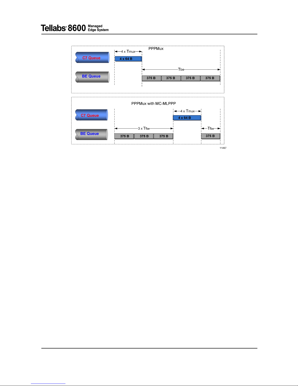
Layer Descriptions
Fig. 11 PPPMux and MC-MLPPP Latency
• Case 1: When PPPMux is enabled with MLPPP
In this case, latency experienced by high priority traffic Tlamux, i.e. the w orst case delay to transmit
a PPP multiplexed frame can be calculated as following:
Tlamux = Tw + Tmux + Tbe
Where:
• Tw is the waiting time for the first CS7 frame before the remaining frames arrived, 3 ms in this
example
• Tmux is the time taken to transmit the PPP multiplexed frame over the link. Tmux = (4*64*8
bits)/1920 kbps = 1.06 ms
• Tbe is the time taken to transmit the whole BE frame. Tbe = (4*375*8 bits)/1920 kbp
s = 6.25 ms
In this case example, a latency of PPP multiplexed frame is 10.31 m s.
• Case 2: When PPPMux is enabled with MC-MLPPP
Tlamux = Tw + Tmux + Tfbe
Where:
• Tfbe is the time taken to transfer one BE fragment. Tfbe = (375*8 bits)/1920 kbps = 1.56 ms
The latency of PPP multiplexed frame when MC -MLPPP is enabled in this example is 5.62 ms.
However, the processing delay (typically less than 1 ms) is also present and thus theoretical delays
will not be achieved exactly.
76.8610-50149A Tellabs®8600 Managed Edge System
© 2011 Tellabs. Tellabs
®
8609 Access Switch FP1.0 Tellabs®8611 Access Switch FP1.1 Interface Configuration Guide
73

Layer Descriptions
Fig. 12 PPPMux and Multi Link Classes
There a re only two multi link classes when MC-MLPPP is en a bled with PPPMux. Although,
multiclass negoti ation can happen with more than 2 classes, the system enforces traffictousetwo
multilink classes; EF and CS7 are placed to the same multilink class because preceding PPPmux
function has already multiplexed CS7 and EF frames to the same PPPmux packet. Rest of the traffic
classes are enforced to another multilink class.
In Fig. 12, when PPPMux i s enabled with multiclass (negotiated with 4 classes), CS7 and EF are
mapped to multi link class 2. Whereas, AF4, AF3, AF2, AF1 and BE are mapped to multi lin k class
0. CS7 and EF are multiplexed to the sam e frame, thus it is not meaningful to allow CS7 suspend
EF and therefore they must be in the same class
Fault Management
The supported TDM fault management function is available as described in chapter 5Fault
Management Operation and Configuration.
Tellabs®8600 Managed Edge System 76.8610-50149A
Tellabs
®
8609 Access Switch FP1.0 Tellabs®8611 Access Switch FP1.1 Interface Configuration Guide © 2011 Tellabs.
74
 Loading...