

Tellabs 7100, 7100N, 7190, 7191, 7194 General Description Manual

®
General Description
76.7144FP51/2
Tellabs® 7100/7100N Optical Transport System
SONET/SDH Systems
®
Tellabs
Tellabs
Tellabs
Revision B, 5/09
Copyright © 2009 Tellabs. All rights reserved.
7190 Element Management System
®
7191 Craft Station
®
7194 Network Management System

FCC Notification
SM
Statement
Federal Communications Commission (FCC) Rules require that you be notified of
the following:
This equipment has been tested and found to comply with the limits for a Class A
digital device, pursuant to part 15 of the FCC Rules. These limits are designed to
provide reasonable protection against harmful interference when the equipment is
operated in a commercial environment. This equipment generates, uses, and can
radiate radio frequency energy and, if not installed and used in accordance with the
instruction manual, may cause harmful interference to radio communications.
Operation of this equipment in a residential area is likely to cause harmful
interference in which case the user will be required to correct the interference at his
own expense.
Changes or modifications not expressly approved by Tellabs Operations, Inc., in
writing can void the user’s authority to operate the equipment.
Industry Canada
Notification Statement
Industry Canada interference-causing equipment regulations require that you be
notified of the following:
This Class A digital apparatus complies with Canadian ICES-003.
Cet appareil numérique de la classe A est conforme à la norme NMB-003 du
Canada.
Copyright Statement This Tellabs manual is owned by Tellabs or its licensors and protected by U.S. and
international copyright laws, conventions, and treaties. Your right to use this manual
is subject to limitations and restrictions imposed by applicable licenses and
copyright laws. Unauthorized reproduction, modification, distribution, display or
other use of this manual may result in criminal and civil penalties.
Trademark Notice The following trademarks and service marks are owned by Tellabs Operations, Inc.,
or its affiliates in the United States and/or other countries: ACCESSMAX
CABLESPAN
EC DUO
INTELLIGENT SERVICE EDGE
NETREACH
®,
®
CEC-128®, DXX®,
, ENHANCED AUDIO PLUS®, EXPRESS/PATH®, FOCUS™,
™
®
, METROCARE , METROVANTAGE™, MetroWatch®,
®
, NETWISE®, SCULPTURED SOUND®, TECHNOLOGY THAT
, MARTIS®,
TRANSFORMS THE WAY THE WORLD COMMUNICATES
®
, TELLABS PROPARTNER™, Tellabs® ServiceAssured™ Upgrade,
®
, DYNAMIC SIGNAL TRANSFER™,
®
, MARTISDXX®,
™
,
TELLABS. THE FUTURE OF YOUR BUSINESS. STARTING NOW
™
THE WORLD COMMUNICATES THROUGH TELLABS
YOUR NETWORKING PARTNER
®
, TITAN®, VERITY®,
®
,
®
, TELLABS®,
™
, TEL/MOR®,
Any other company or product names may be trademarks of their respective
companies.
Contact Information In an effort to improve the quality of this document, please notify Tellabs Technical
Assistance at 1.800.443.5555 in North America or 1.630.798.7070 outside North
America if any anomalous conditions are observed.

General Description Contents
Contents Page
Section 1 Introduction 2-1
Reason for Issue ................................................................................... 2-1
Section 2 Tellabs 7100/7100N Optical Transport Series 2-2
DWDM and the Optical Layer ............................................................................ 2-2
Multiplexing Schemes .................................................................................. 2-2
Layer Management ...................................................................................... 2-3
Tellabs 7100/7100N OTS Operations ................................................................ 2-3
Tellabs 7100/7100N OTS Configurations .................................................... 2-5
Embedded Operations Channel Network .................................................... 2-7
Autodiscovery .............................................................................................. 2-8
Performance Monitoring .............................................................................. 2-8
Control Plane ............................................................................................... 2-8
Ethernet Packet Support.............................................................................. 2-9
SDH Protocol Support ............................................................................... 2-10
Interoperability Features .................................................................................. 2-11
Data Communications Channel (DCC)...................................................... 2-11
IP Over DCC.............................................................................................. 2-11
OSI Traffic Tunnelled Over EON to Remote NEs ...................................... 2-11
Services Between Transponders and External Equipment .............................. 2-11
System Operation and Growth ......................................................................... 2-12
SPM Operation .......................................................................................... 2-12
Auto-Negotiation ........................................................................................ 2-12
Seamless Expansion ................................................................................. 2-12
Network Administration .................................................................................... 2-13
Northbound Interfaces ............................................................................... 2-13
DHCP......................................................................................................... 2-13
Power Balancing ........................................................................................ 2-14
Derived Timing Synchronization ................................................................ 2-14
Section 3 Features Introduced in FP5.1.x 2-15
Control Plane Enhancements .......................................................................... 2-15
Packet Enhancements ..................................................................................... 2-16
Expanded Module Support in Tellabs 7100N OTS .......................................... 2-17
88-Channel Configurations .............................................................................. 2-17
Expanded Shelf Capacity ................................................................................. 2-17
Expanded Y-cable Patch Panel Support .......................................................... 2-17
DCC Enhancements ........................................................................................ 2-17
NorthBound Interface Enhancements .............................................................. 2-18
Management Systems Features ...................................................................... 2-18
FP5.1.x Hardware ............................................................................................ 2-19
71188-IR LIAM-E88 Line Input Amplifier Module - Enhanced 88-Channel 2-19
71188-LR LRAM-E88 Long Reach Amplifier Module - Enhanced
88-Channel ................................................................................... 2-19
71188-ER ELRAM-E88 Extended Long Reach Amplifier Module -
Enhanced 88-Channel .................................................................. 2-19
71123C Line Output Amplifier Module - Enhanced 88 Channel ................ 2-19
71887B 8-Degree Reconfigurable Multiplexer Module - 88 Channel ........ 2-20
New Revision of Tellabs 7100 OTS Shelves ............................................. 2-20
714144 OMD44-1 and 714188 OMD44-45 Mux/Demux Modules............. 2-20
76.7144FP51/2, Rev B 5/09 Page 2-i

Contents General Description
Contents Page
83.71020 Generic Breaker Frame Alarm Panel......................................... 2-20
71125A Network Interfaced Raman........................................................... 2-20
71125B Co-Propagating Raman Amplifier 700 mW .................................. 2-21
82.71114B System Processor Module ...................................................... 2-21
Dispersion Compensation Module............................................................. 2-21
71328O-M Optical Transport Network Multiplexer..................................... 2-21
71423M 40 Gbps, Multi-Port Tunable Transponder Module (FGTM-M) .... 2-21
82.71423 40 Gbps Transponder Module (FGTM) ..................................... 2-22
SONET/SDH Switching Modules (SSMs).................................................. 2-22
Section 4 Management Systems Graphical Interface Software 2-23
Tellabs 7190 EMS and Tellabs 7194 NMS ...................................................... 2-23
Tellabs 7190 Element Management System Features.............................. 2-24
Tellabs 7194 Network Management System Features .............................. 2-24
Tellabs 7190 SNMP Northbound Interface (Per NE) ................................. 2-24
Tellabs 7194 XML Northbound Interface (Per NE) .................................... 2-25
Tellabs 7191 Craft Station................................................................................ 2-25
Tellabs 7196 Optical Subnet Planner............................................................... 2-25
Tellabs Management Systems Architecture..................................................... 2-26
Network Management Features....................................................................... 2-29
One-Step Upgrades ................................................................................... 2-29
NE Status Indicators .................................................................................. 2-29
NE Metering Manages High-Volume Messaging Periods.......................... 2-29
NE Parameters Exported to Tellabs 7196 Planning Tool .......................... 2-29
Primary and Secondary Database Backup................................................ 2-30
Database Restore...................................................................................... 2-30
Software Upgrades .................................................................................... 2-30
Multiple NE Operations .............................................................................. 2-31
User Security Partitioning .......................................................................... 2-31
®
Oracle
Retrieving Network Element TL1 Logs ...................................................... 2-31
Shelf Views with Active LEDs .................................................................... 2-32
Fault and Alarm Management.......................................................................... 2-32
Diagnostics ................................................................................................ 2-32
Alarm Profile Management ........................................................................ 2-32
Alarm Synchronization ............................................................................... 2-32
Alarm Filtering............................................................................................ 2-32
Alarm Sorting Based on Multiple Criteria................................................... 2-33
Alarm/Event Time Zone ............................................................................. 2-33
Automatic Acknowledge of Transient Conditions ...................................... 2-33
Root Cause Analysis ................................................................................. 2-33
Security Management ...................................................................................... 2-34
Configuration Management .............................................................................. 2-34
Provisioning Features ...................................................................................... 2-35
Provisioning Defaults ................................................................................. 2-35
Centralized Configuration for STSn and VCn ............................................ 2-35
Wavelength Manager................................................................................. 2-35
Network Views ........................................................................................... 2-35
TID/CLLI Coordinates Import ..................................................................... 2-36
Circuit Views .............................................................................................. 2-36
Circuit Discovery (Optical Layer) ............................................................... 2-36
End-To-End Provisioning of Circuits on Optical Layer............................... 2-37
Data Guard .................................................................................. 2-31
Page 2-ii 5/09 76.7144FP51/2, Rev B

General Description Contents
Contents Page
End-to-End Sub-Circuit Management........................................................ 2-37
End-to-End RPR Circuit Management....................................................... 2-37
Lightpath Power Levels ............................................................................. 2-37
Performance Monitoring ................................................................................... 2-38
Consolidated Performance Monitoring (PM).............................................. 2-38
Performance Reports................................................................................. 2-38
Section 5 System Applications 2-39
Control Plane Applications ............................................................................... 2-40
Point-to-Point Topology.................................................................................... 2-41
DWDM Ring Networks ..................................................................................... 2-41
Tellabs 7100N OTS.......................................................................................... 2-42
Mesh Network .................................................................................................. 2-43
Direct Connect Overview ................................................................................. 2-44
Spur Applications ............................................................................................. 2-46
Section 6 Physical Configurations 2-48
FP5.1.x Configurations..................................................................................... 2-49
44-Channel Configurations ........................................................................ 2-49
8-Degree Reconfigurable SBOADM (ROADM)................................... 2-49
4-Degree Reconfigurable SBOADM (ROADM)................................... 2-50
Tellabs 7100N SBOADM..................................................................... 2-50
44-Channel OLA ................................................................................. 2-50
88-Channel Configurations ........................................................................ 2-50
8-Degree, 88-Channel Reconfigurable SBOADM (ROADM) .............. 2-50
88-Channel OLA ................................................................................. 2-50
Main Shelf Modules for SBOADM Configurations............................................ 2-51
Tellabs 7100 SBOADM Main Shelf............................................................ 2-52
Tellabs 7100N SBOADM Main Shelf ......................................................... 2-58
Main Shelf Modules for OLA Configurations .................................................... 2-59
Tellabs 7100 OTS OLA.............................................................................. 2-60
Tellabs 7100N OTS OLA ........................................................................... 2-61
Port Shelf Modules for SBOADM Configurations ............................................. 2-63
Tellabs 7100 OTS Port Shelf ..................................................................... 2-63
Packet Subsystem in Tellabs 7100 OTS Port Shelf .................................. 2-64
Tellabs 7100N OTS Port Shelf .................................................................. 2-65
Signal Flow Diagrams ...................................................................................... 2-66
SBOADM/ROADM Configuration in Tellabs 7100N OTS .......................... 2-67
SBOADM/ROADM Configurations with Two RCMM-4D/8D ...................... 2-68
SBOADM/ROADM Configurations with Four RCMM-4D/8D ..................... 2-69
SBOADM/ROADM Configurations with Eight RCMM-4D/8D .................... 2-70
SBOADM/ROADM Configurations with Eight RCMM 8D88s .................... 2-71
SBOADM/ROADM Configurations with One Shelf .................................... 2-72
Signal Flow for a SBOADM/ROADM for Port-Side Protection................... 2-73
Signal Flow for SBOADM/ROADM with Line-Side Protection ................... 2-74
Signal Flow for Spur Application with Port-Side Protection ....................... 2-75
Tellabs 7100 OTS OLA Configurations ..................................................... 2-76
Tellabs 7100N OTS OLA Configurations................................................... 2-77
76.7144FP51/2, Rev B 5/09 Page 2-iii

Contents General Description
Contents Page
Section 7 System Architecture 2-78
Tellabs 7100/7100N OTS Shelves................................................................... 2-79
Tellabs 7100 OTS Modules .............................................................................. 2-79
System Processor Module (SPM).............................................................. 2-79
82.71114B System Processor Module ...................................................... 2-80
Amplified Interface Module (AIM) .............................................................. 2-80
Data Processor Module (DPM) .................................................................. 2-80
Line Input Amplifier Module-Enhanced (LIAM-E) ...................................... 2-80
Long Reach Amplifier Module-Enhanced (LRAM-E) ................................. 2-80
Extended Long Reach Amplifier Module-Enhanced (ELRAM-E)............... 2-81
Line Output Amplifier Module-Enhanced (LOAM-E).................................. 2-81
Line Input Amplifier Module - Enhanced 88-Channel (LIAM-E88) ............. 2-81
Long Reach Amplifier Module - Enhanced 88-Channel (LRAM-E88)........ 2-81
Extended Long Reach Amplifier Module - Enhanced 88-Channel
(ELRAM-E88) ............................................................................... 2-81
Line Output Amplifier Module - Enhanced 88 Channel (LOAM-E88) ........ 2-82
Channel Pass-Through Module (CPM)...................................................... 2-82
Reconfigurable Channel Multiplexer Module (RCMM-xD)......................... 2-82
Reconfigurable Channel Multiplexer Module-Spur (RCMM-S) .................. 2-82
8-Degree Reconfigurable Multiplexer Module - 88 Channel
(RCMM-8D88) .............................................................................. 2-83
Channel Multiplexer Module - 44 Channel (CMM-44) ............................... 2-83
714144 OMD44-1 and 714188 OMD44-45 Mux/Demux Modules............. 2-83
SONET/SDH/Packet Fabric Module (SPFAB)........................................... 2-83
Dispersion Compensation Module (DCM) ................................................. 2-84
71125A Network Interfaced Raman........................................................... 2-84
71125B Co-Propagating Raman Amplifier 700 mW .................................. 2-84
Filler Modules ............................................................................................ 2-85
XFP/SFP Management .............................................................................. 2-85
Optical Protection and Synchronization Module (OPSM) .......................... 2-85
Tellabs 7100N OTS Modules ........................................................................... 2-86
System Processor Module (SPM-N) .......................................................... 2-86
Colorless Core Module (CCM-xR) ............................................................. 2-86
Optical Line Amplifier ................................................................................. 2-87
88-Channel Input Amplifiers ...................................................................... 2-87
Filler Modules ............................................................................................ 2-87
Tellabs 7100/7100N OTS Transponders ......................................................... 2-88
Multirate Transponder Module-Enhanced (MRTM-E)................................ 2-88
Universal 10G Transponder Module-Tunable (TGTM-T)........................... 2-88
81.71323-NX Enhanced 10G Transponder Module (TGTM-E) ................. 2-88
81.71423 40G Transponder Module (FGTM) ............................................ 2-89
82.71423 40 Gbps Transponder Module (FGTM) ..................................... 2-89
Subrate Multiplexer Transponder Module (SMTM-x)................................. 2-89
71328O-M Optical Transport Network Multiplexer (OTNM-D) ................... 2-90
10G Subrate Multiplexer Transponder Module - Packet (SMTM-P) .......... 2-90
10G Transponder - Packet Interface Module (TGIM-P)............................. 2-90
SONET/SDH Switching Modules (SSMs).................................................. 2-91
Tellabs 7100 OTS Common Equipment .......................................................... 2-92
88-Channel Shelves .................................................................................. 2-92
83.71020 Generic Breaker Frame Alarm Panel......................................... 2-92
Breaker Frame Alarm Panel (BFAP) ......................................................... 2-92
Breaker Frame Alarm Module (BFAM) ...................................................... 2-93
Alarm Interface Panel (AIP) ....................................................................... 2-93
Page 2-iv 5/09 76.7144FP51/2, Rev B

General Description Contents
Contents Page
Fan Assembly ............................................................................................ 2-93
Horizontal Distribution Panel Modules....................................................... 2-94
Tellabs 7100N OTS Common Equipment ........................................................ 2-95
Shelf with Fan Tray .................................................................................... 2-95
Telemetry and Timing Module ................................................................... 2-95
Shelf Display Module................................................................................. 2-95
SPM-N ....................................................................................................... 2-95
Facility and System Alarms .............................................................................. 2-96
Alarm Generation....................................................................................... 2-96
Signal Monitoring ....................................................................................... 2-97
System Reliability ............................................................................................. 2-98
System Security......................................................................................... 2-99
IP Security ............................................................................................... 2-100
Network Protection Features.......................................................................... 2-100
Line-Side Protection ................................................................................ 2-100
Port-Side Protection on SMTM-U ............................................................ 2-100
OPSM Hold-Off Timer.............................................................................. 2-101
End-to-End Circuit LOS Propagation....................................................... 2-101
Y-Cable Patch Panel ............................................................................... 2-101
The OSI Data Communication Channel......................................................... 2-102
Section 8 Performance and Maintenance Features 2-104
Facility Alarm Monitoring ................................................................................ 2-104
Alarm Management ........................................................................................ 2-104
Alarm Types............................................................................................. 2-105
TL1 Interface............................................................................................ 2-105
Facility Performance Monitoring..................................................................... 2-106
TL1 Ethernet PM...................................................................................... 2-106
SNMPv3 and RMON Support to Receive Ethernet PM ........................... 2-106
Path Level PM ......................................................................................... 2-107
Transponder BER Test Signal Generation .............................................. 2-107
Accumulation and Storage....................................................................... 2-107
Optical Threshold Crossing Alert (OTCA)................................................ 2-108
End-to-End Circuit LOS Propagation ............................................................. 2-108
Client Laser Shutdown............................................................................. 2-109
Port-Side OPSM Protection ..................................................................... 2-110
Line-Side OPSM Protection ..................................................................... 2-111
Maintenance Loopbacks ................................................................................ 2-112
Signal Protection ............................................................................................ 2-115
Network Protection with OPSM...................................................................... 2-117
Network Protection with OTNM-Ds ................................................................ 2-118
Network Protection with Switch Fabric........................................................... 2-119
Network Protection with Paired Transponders ............................................... 2-120
Network Equipment Protection with Y-Cable Patch Panel ............................. 2-121
Network Equipment Protection with OPSM.................................................... 2-122
Client Protection with Paired Transponders ................................................... 2-123
Unprotected Scenario .................................................................................... 2-124
External Protection ......................................................................................... 2-125
Chromatic Dispersion ..................................................................................... 2-126
How to Calculate ..................................................................................... 2-128
Polarization Mode Dispersion ........................................................................ 2-129
76.7144FP51/2, Rev B 5/09 Page 2-v

Contents General Description
Contents Page
Index 2-131
Page 2-vi 5/09 76.7144FP51/2, Rev B

General Description 1. Introduction
1. Introduction
1.01 This document provides an overview of Tellabs 7100
System (OTS) series of products and network configurations, including the Tellabs
®
7100N
configurations, and applications. It also provides an overview of dense wavelength
division multiplexing (DWDM) technology, including multiplexing schemes and
optical layer management. A detailed description of system architecture and
hardware is provided.
1.02 This document is intended for network planners and engineers. Customers
can use this document to determine the suitability of implementing Tellabs 7100
OTS and Tellabs 7100N OTS technology into their optical networks. Users of this
manual should be familiar with telephone industry technology.
Reason for Issue 1.03 Tellabs reissues this manual from Revision A to Revision B to include the
changes in Table 1.1, page 2-1. Change bars indicate the changes Tellabs made
from the previous to latest revision.
Table 1.1 General Description Revision History
Revision Change History Release Date
A Initial release for Tellabs 7100 Optical Transport System FP5.1.x. 1/09
B Update Features Introduced in FP5.1.x, page 2-15 and support for those features
throughout the document.
Optical Transport System (OTS). It details system features,
®
Optical Transport
5/09
76.7144FP51/2, Rev B 5/09 Page 2-1

2. Tellabs 7100/7100N Optical Transport Series General Description
2. Tellabs 7100/7100N Optical Transport Series
2.01 This section provides an overview of DWDM systems and the Tellabs
7100/7100N OTS operations.
DWDM and the Optical Layer
2.02 Dense wavelength division multiplexing (DWDM) is an optical technology
used to increase the capacity and flexibility of the optical infrastructure. In a DWDM
system, multiple optical signals are transmitted over multiple optical wavelengths
on a single optical fiber. Traditional systems require multiple optical fibers to
transmit multiple optical signals.
2.03 DWDM is a multiplexing hierarchy that leverages the optical layer of the
transmission network. The optical layer interfaces the digital layer at the optical
termination equipment, which can be considered part of both the electrical and the
optical layer. The optical layer provides multiplexing schemes and management
that are not present on the digital layer of the network.This optical infrastructure
supports multiple data rates (for example, 622 Mbps, 2.5 Gbps, 10 Gbps),
synchronous optical network (SONET) signal rates, and synchronous digital
hierarchy (SDH) signal rates.
Multiplexing Schemes
2.04 DWDM systems are divided into integrated and open systems. In
integrated DWDM systems, the DWDM transmitter and receiver functionality is
integrated into the transmitter/receiver of the digital transmission equipment. In
open DWDM systems, special DWDM transmitter/receiver interface units
(transponders) are used to provide the interface between the DWDM multiplexers
and the adjacent digital transmission equipment.
2.05 In DWDM systems, the signals to be multiplexed and demultiplexed are
characterized by different optical wavelengths. The optical wavelengths of the
Tellabs 7100/7100N OTS are chosen in agreement with the International
Telecommunications Union (ITU-T) recommendations specifying up to 44 DWDM
channels with center wavelengths placed in the erbium doped fiber amplifier
(EDFA) gain band with 100 GHz between neighboring channels, and 88 DWDM
channels with center wavelengths placed in the erbium doped fiber amplifier
(EDFA) gain band with 50 GHz between neighboring channels. Wavelengths are
placed from 1529 nm to 1563 nm, where the EDFA gain bands exhibit the most
wavelength uniform gain characteristics.
Page 2-2 5/09 76.7144FP51/2, Rev B

General Description 2. Tellabs 7100/7100N Optical Transport Series
Layer Management
2.06 The optical layer is managed as the digital (SONET/SDH) layer is, except
for the physical transport of remote management data. In the optical layer,
supervisory and management data from remote DWDM equipment cannot be
transmitted over embedded digital channels. Instead, this data is transmitted over
an independent optical supervisory channel (OSC) at 1510 nm. The OSC is
terminated, processed, and retransmitted at the DWDM equipment that interfaces
the optical transmission fiber.
Tellabs 7100/7100N OTS Operations
2.07 The Tellabs 7100 OTS is a metro, dense wavelength division multiplexing
(DWDM) system based on a parallel architecture that provides scalable,
non-service affecting growth to 88 protected wavelengths without network
re-engineering. The Tellabs 7100N OTS is a full-featured system providing eight
protected wavelength for niche applications within a Tellabs 7100 OTS network.
These systems support ITU-T Recommendation G.709 Optical Transport Network
(OTN)-based transport, enabling transparent high-capacity services. Services
such as Carrier Ethernet, video, Storage Area Network, SONET, and SDH are
carried on a shared infrastructure, scaling capacity as needed.
2.08 The Tellabs 7100/7100N OTS is built on unique, multi-patented system
technologies that enable true next generation multiservice delivery. It features an
integrated dynamic optical core combined with an intelligent services interface that
delivers Add/Drop Multiplexer (ADM) capability on a single blade (SMTM-U
module) in client ranges of 100 Mbps to 40 Gbps. The dynamic optical core
enables service providers to meet today’s network needs while supporting the
ability to effortlessly deploy additional nodes for future expansion via a
multi-degree Reconfigurable Optical ADM (ROADM).
2.09 The intelligent services interface can replace a currently installed ADM ring
with a simple pair of modules, eliminating the costly implementation of stacked
ADM rings, back-to-back ADM boxes between rings, and multiple rows of
supporting equipment. Linear add/drop, ring, and mesh optical network topologies
are supported on the same base platform. Service is easily changed by equipping
endpoints with specific interface modules.
2.10 Tellabs 7100/7100N OTS provides the following benefits:
• fiber relief in fiber-constrained networks
• wavelength and capacity-based services
• deployment of new services without re-engineering networks
• efficient aggregate and transport of different types of traffic in
metropolitan (metro) areas
• variable applications such as mesh, ring, and point-to-point
76.7144FP51/2, Rev B 5/09 Page 2-3

2. Tellabs 7100/7100N Optical Transport Series General Description
2.11 The Tellabs 7100/7100N OTS offers a single, flexible platform that can
support current ADM and Wavelength Division Multiplexing (WDM) ring
capabilities and ensure a smooth migration to future packet-based services over
mesh networks. This section provides an overview of the Tellabs 7100 optical
transport series of products. The Tellabs 7100 series includes the following
products.
• Tellabs 7100 Optical Transport System (OTS)
• Tellabs 7100N Optical Transport System (OTS)
• Tellabs 7190
®
Element Management System (EMS)
• Tellabs 7191® Craft Station
• Tellabs 7194
• Tellabs 7196
®
Network Management System (NMS)
®
Optical Subnet Planner
2.12 Hardware elements of the Tellabs 7100/7100N OTS provide support for
higher bandwidth applications and enhanced access. Hardware modules include
2.5G, 10G, and 40G transponders, reconfigurable multiplexers, multiplexers to
support spur applications, packet multiplexers, colorless core multiplexers for
high-density metro applications, optical protection modules, SONET/SDH/Packet
module for digital cross-connects, intermediate- and long-reach amplifiers, system
processors, and data processors. Multirate transponders interface transmission
equipment at client rates between 100 Mbps and 10.7 Gbps, including Fibre
Channel, OC-3/STM-1, OC-12/STM-4, OC-48/STM-16, OC-192/STM-64,
OC-768/STM-256, Gigabit Ethernet (GbE), OTU2, OTU3, and 10 GbE.
Tellabs 7100N OTS 2.13 The Tellabs 7100N OTS is a compact version of the Tellabs 7100 OTS that
can add or drop eight protected wavelengths and pass through up to 88
simultaneous channels. This product provides a 2-degree DWDM system
(populated in 1-degree increments) comprised of up to seven 30-AMP shelves and
a subset of Tellabs 7100 OTS transponder modules. It can be deployed as a
one-shelf optical line amplifier (OLA), six-shelf OLA to support direct connect
applications, or as a 2-degree SBOADM with one main shelf and up to six port
shelves in 19- or 23-inch racks. The following modules are deployed in this
application: SPM-N, CCM-IR, CCM-LR, OLA-IR, OLA-LR, LIAM-E88, LRAM-E88,
ELRAM-E88, BFM, and CFM. This system also supports the following
transponders: SSM-D, SSM-X, OTNM-D, FGTM, FGTM-M, SMTM-P, TGIM-P,
82.SMTM-U, 82.TGTM-E, and 82.MRTM-E. Slots are paired in the shelf backplane
to accommodate interdependent module applications.
Tellabs 7190/7194
Management Systems
2.14 The Tellabs 7190/7194 management systems (Tellabs 7190 EMS and
Tellabs 7194 NMS) provide integrated management of Tellabs 7100/7100N OTS
NEs.The software features listed below provide support for higher bandwidth
applications and enhanced access capabilities:
• performance monitoring of optical, Packet, SONET, SDH, and
Ethernet traffic
• automatic optical power management and equalization
• end-to-end provisioning at one screen
• automatic laser transmit power shutdown upon fiber cut and automatic
turn-up following restoration
• optical supervisory channel at OC-3/STM-1 rate
Page 2-4 5/09 76.7144FP51/2, Rev B

General Description 2. Tellabs 7100/7100N Optical Transport Series
• CLI interface for packet signaling
• TL1 Gateway Network Element (GNE) functionality
• Embedded Operations Network (EON)
• TL1 interface for system management
• XML/TMF/SNMP/CORBA Northbound Interfaces
Tellabs 7100/7100N OTS Configurations
2.15 Tellabs 7100/7100N OTS supports the following 44- and 88-channel
network configurations in FP5.1.x:
2.16 The following network configurations are supported:
__ Tellabs 7100 Single Bay OADM (SBOADM) - The Tellabs 7100 OTS
single bay optical add/drop multiplexer (SBOADM) is a single network
element with multiple DWDM interfaces. A four-degree SBOADM
requires one main shelf, supports up to eight port shelves, and
operates within a 44-channel plan. An eight-degree SBOADM requires
two main shelves and supports up to eight port shelves, and operates
within a 44- or 88-channel plan.
__ Tellabs 7100 Optical Line Amplifier (OLA) - a 44- or 88-channel OLA
can be configured for short, medium, or long spans. The OLA does not
support add/drop functions, but can be upgraded to a 2-degree node
SBOADM without affecting traffic.
__ Tellabs 7100N OTS SBOADM - the main shelf has up two DWDM
interfaces, A-side through B-side and supports eight protected
wavelengths. The Tellabs 7100N OTS SBOADM is supported only in
44-channel systems.
__ Tellabs 7100N OLA - a 44- or 88-channel OLA can be configured for
short, medium, or long spans. The OLA passes through up to 44
channels and does not support add/drop functions. This OLA is
interchangeable with Tellabs 7100 44-channel OLA.
Note: For complete descriptions of Tellabs 7100/7100N system modules and
slot assignments per configuration, refer to Tellabs 7100 System
Engineering and Tellabs 7100N System Engineering.
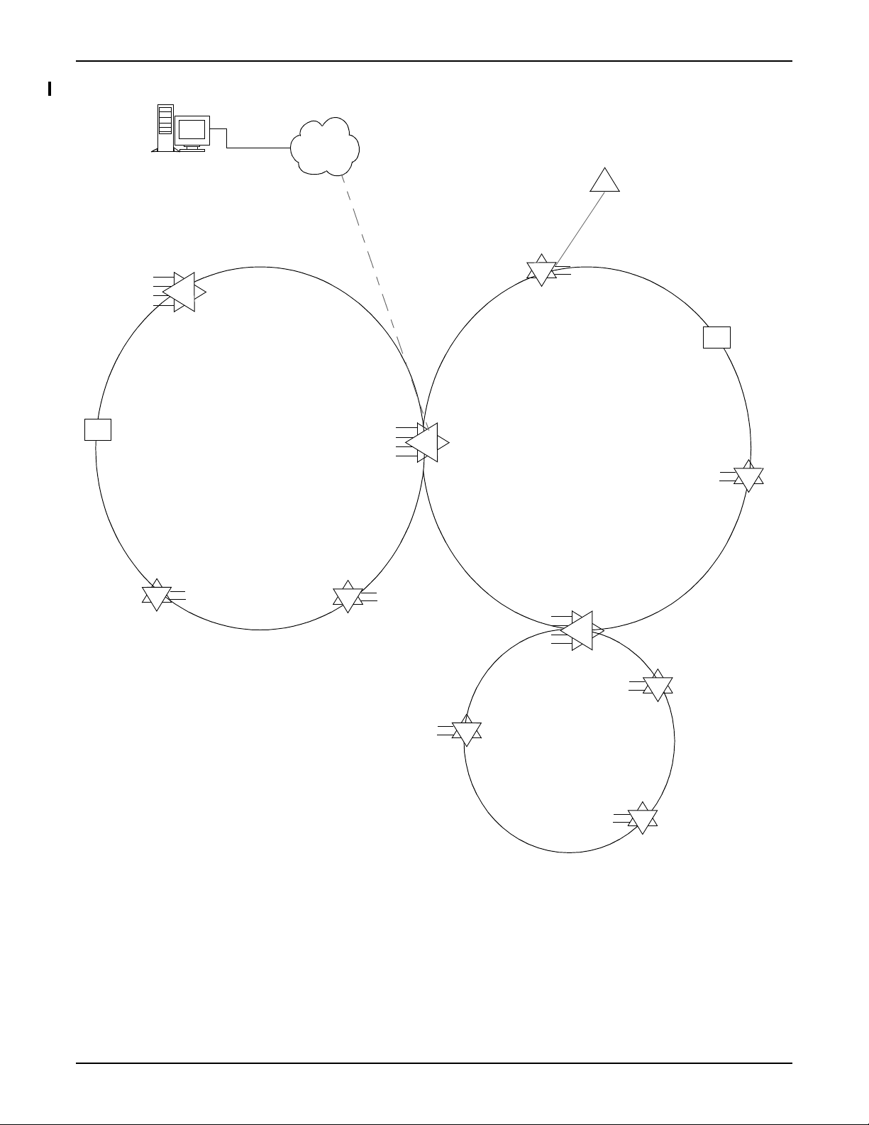
2.17 A sample network of Tellabs 7100 series of products is illustrated in Figure
2.1, page 2-6.
76.7144FP51/2, Rev B 5/09 Page 2-5
2. Tellabs 7100/7100N Optical Transport Series General Description
DCN
Tellabs 7190 EMS
Tellabs 7194 NMS
Spur
2-degree
SBOADM
Tellabs 7100N
2-degree
SBOADM
Tellabs 7100N
2-degree
SBOADM
Tellabs 7100N
4-degree
SBOADM
Tellabs 7100
2-degree
SBOADM
Tellabs 7100
4-degree
SBOADM
Tellabs 7100
4-degree
SBOADM
Tellabs 7100
(also the PGNE)
2-degree
SBOADM
Tellabs 7100
OLA
Tellabs 7100N
2-degree
SBOADM
Tellabs 7100N
OLA
Tellabs 7100N
2-degree
SBOADM
Tellabs 7100N
N
N
N
N
N
N
N
Figure 2.1 FP5.1.x Tellabs 7100/7100N Series Optical Transport Products Network
Page 2-6 5/09 76.7144FP51/2, Rev B
General Description 2. Tellabs 7100/7100N Optical Transport Series
DCN
Ring 1
Ring 2
EMS or OSS
Remote Management (TL1 or Telnet)
PGNE-1-1
PGNE-1-2
PGNE-2-1
PGNE-2-2
EON domain #1
EON domain #2
Link B
Link A
= PGNE
= PRNE
Embedded Operations Channel Network
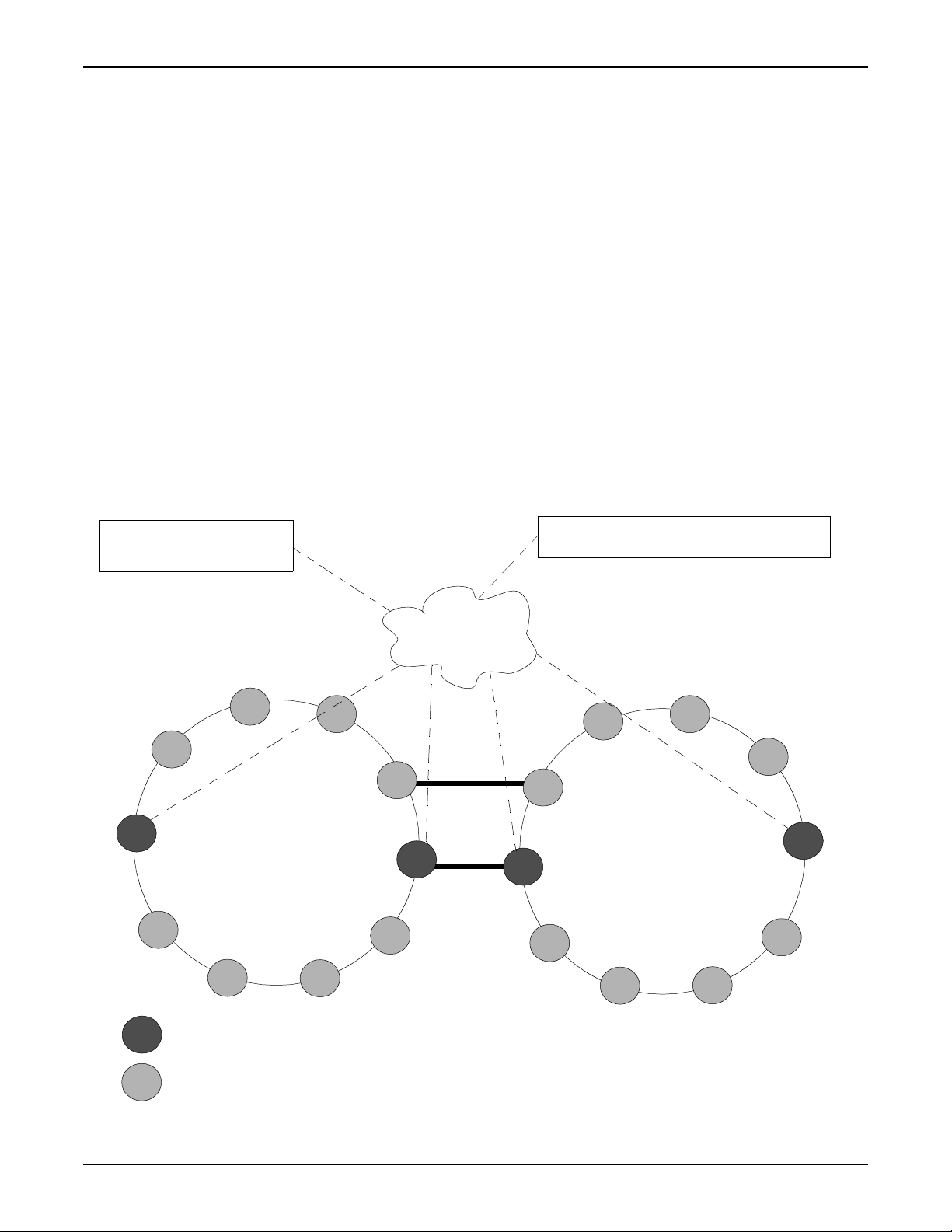
2.18 The Embedded Operations Channel Network (EON) provides Embedded
Operations Channels (EOCs) to route management traffic using Internet Protocol
(IP) through an internal network among the NEs.
2.19 One NE in the EON is provisioned as a gateway NE (PGNE-1) and routes
management traffic between the external DCN and the other NEs (PRNEs) in the
EON. The PGNE-1 manages PRNEs through the Tellabs 7190 EMS and Tellabs
7194 NMS, acting as an entry point from the external DCN and enables packet
routing among the PRNEs after an IP address is configured for each. A secondary
gateway (PGNE-2) provides redundancy so that a single optical link failure does
not cause a communication interruption between the Tellabs 7190/7194
management systems and any NE in the ring.
2.20 Tellabs recommends limiting to 30 the number of PRNEs assigned to a
PGNE. When a network exceeds this limit, the EON can be partioned into two
EONs by provisioning one of the PRNEs as a second PGNE-1 and modifying the
traffic paths around that PRNE. Refer to the Tellabs 7100/7100N Craft Station User
Guide for detailed procedures on partitioning NEs. Figure 2.2, page 2-7 illustrates
the resulting two EONs interconnected via DWDM links after partitioning.
Figure 2.2 Embedded Operations Network
76.7144FP51/2, Rev B 5/09 Page 2-7

2. Tellabs 7100/7100N Optical Transport Series General Description
Autodiscovery
2.21 Autodiscovery is a self-inventory feature that enables the Tellabs
7100/7100N NEs to report their inventory to the Tellabs 7190/7194 management
systems. On system startup, the NE performs a self survey to determine which
hardware components are present. This information is retrieved by the system
manager when it is connected to the NE. If there is a discrepancy between the
configurations stored by the management system and the NE, the NE is assumed
to have the valid configuration.
Performance Monitoring
2.22 Performance monitoring is the continuous, nonintrusive collection of
system performance data and is used to determine the operational status of the
network and the quality of service that the network is providing. PM checks for
specific types of signal information and helps identify the cause of network
transmission problems. PM is detailed in Facility Performance Monitoring,
page 2-106.
Control Plane
2.23 The Tellabs 7100 OTS Control Plane feature provides rapid circuit
provisioning across mesh architectures in transport networks. Control plane
functionality is based on the ITU-T automatically switched optical network (ASON)
architecture and utilizes IETF generalized multi-protocol label switching (GMPLS)
protocols as extended by the OIF. It is embedded in the SPM and applied at STS
or VC termination points on paired SMTM-U module facilities operating in SPFAB
mode.
2.24 NEs are network aware in control plane applications, providing faster
set-up and tear-down of call paths across the network. The call path is established
at the STS or VC layer. The control plane automatically manages a link resource
database in real-time to provide constraint-based routing and traffic engineering.
The Tellabs 7100 OTS control plane application interfaces traditional and
management plane systems to coordinate traffic and network resources.
2.25 Tellabs 7100 OTS Control Plane supports calls across multiple domains
and flexible path protection at the STS/VC level. Re-designed protection schemes
in FP5.1.x streamline provisioning requirements while enhancing reliability to
control plane traffic.
2.26 Control Plane 1+1 (CP 1+1) protection provides two diverse connections
(working and protected) between the ingress node and the egress node of a
protection domain. This protection scheme is supported on the drop-side and the
line-side between Tellabs 7100 OTS NEs within the Tellabs 7100 OTS control
plane network (I-NNI). CP 1+1 protection is not supported on drop-side or line-side
facilities provisioned between a Tellabs 7100 OTS NE and control plane entities
outside of the Tellabs 7100 OTS network where only LAPS is supported over the
E-NNI.
Page 2-8 5/09 76.7144FP51/2, Rev B

General Description 2. Tellabs 7100/7100N Optical Transport Series
2.27 Flexible Path Protection is a protection scheme that removes previous
shelf-slot pairing constraints and enables protection port pairing between any two
ports on the line side, or any two ports on the drop side. It allows any port-side
termination to be protected by any other port-side termination and any line-side
termination to be protected by any other line-side termination within the same shelf.
Protection port pairing with a line-side port and a drop-side port mixed pair is not
supported. A protection port pair constitutes a Path Protection Group (PPG)
supported by STSn/VCn path layer protection. These Path Protection Groups
(PPG) are automatically created when the cross-connect is provisioned. For CP
1+1, two PPGs are created – one at the ingress/source node, and one at the
egress/destination node.
2.28 Dynamic re-route supports multiple repair points for a signal path and
permits automatic recovery from node failures with an efficient use of resources
that are used only during route restoration, unlike Control Plane 1+1 (CP 1+1)
protection where resources are pre-allocated. Dynamic re-route is supported in
single domains and across multiple domains. When dynamic re-route restoration
is provisioned, failure indications are propagated to repair nodes to direct an
alternate route connection to bypass the call path. In the event of resource
contention among multiple dynamic calls or simultaneous failures along the call
path, crankback is used to address these conditions and retry failed calls.
Ethernet Packet Support
2.29 Packet subsystems are created on Tellabs 7100 OTS port shelves when
packet modules (DPM, SPFAB, SMTM-P, and TGIM-P) are present and
provisioned. Packet subsystems are created on Tellabs 7100N OTS port shelves
when SMTM-P or TGIM-P are present and provisioned. The Packet subsystem
can be managed with the Tellabs 7190/7194 management system or a Command
Line Interface (CLI). Packet-based transponder modules, SMTM-P and TGIM-P,
manage the ingress and egress ports for traffic flow. SMTM-P modules are
equipped with small form pluggables (SFPs) designed to support traffic signal rates
that interface the module. Refer to Table 2.1, page 2-9.
Table 2.1 SMTM-P/TGIM-P Specifications
Port Interfaces SMTM-P TGIM-P
Number of Interfaces 10 1
Pluggable Optics SFP-based XFP-based
Data Rates 10 Mbps–1 Gbps 10 Gbps
Protocols 10/100/1000 Mbps
BaseT
GbE (1 G Optical)
100Base-FX
10 G Ethernet LAN
2.30 Supported features include MAC Bridging, VLAN Bridging, an 802.3
compliant MAC client interface, Packet security, Packet fault management, Packet
performance monitoring, multicasting, synchronized Ethernet, and line-side RPR
protection.
76.7144FP51/2, Rev B 5/09 Page 2-9

2. Tellabs 7100/7100N Optical Transport Series General Description
2.31 In Tellabs 7100 OTS applications, the SONET/SDH/Packet Fabric
(SPFAB) module provides a switch matrix for SONET/SDH signaling and Packet
traffic to maximize system integration and bandwidth efficiency. It interfaces
SMTM-U, SMTM-P, and TGIM-P modules to switch Packet and STS/VC-level
cross-connects.
2.32 Packet applications support both SNMPv2 and SNMPv3. Quality of
service certifications include Metro Ethernet Forum (MEF) services certification:
E-Line service, E-LAN service, and Ethernet Private Line (EPL). Performance
monitoring enhancements include Weighted Random Early Detection (WRED)
congestion management, traffic-shaping queues, and continuity checks.
2.33 Improved fault management for 802.3 compliant MAC/PHY interfaces
include Far End Fault Indication (FEFI) for 100FX interface, LOSYNC for NE IEEE
802.3 compliant MAC interface, signal degrade and signal fail conditions detected
on incoming Ethernet traffic based on errored frames, provisionable alarm profiles,
and additional alarms and conditions retrieved via SNMPv2c traps.
2.34 Traffic enhancements include tunneling Layer 2 control frames
transparently (spanning tree bridge protocol data units and GVRP packets) at
Provider Edge Bridge points. Ethernet types are filtered at the module port to
reduce congestion. Link aggregation groups are managed by SNMPv2.
SDH Protocol Support
2.35 A suite of Tellabs 7100 OTS and Tellabs 7100N OTS features are provided
in SDH signaling formats. Transparent STMnT (Synchronous Transfer Mode)
signals are introduced to multiplex SDH-based traffic onto a single fiber to reduce
fiber exhaust. STMnTs transport Virtual Containers (VC-4, VC-4-4C, or VC-4-16C)
through the network untouched.
2.36 This feature also uses VCn grooming to support multiple types of traffic,
including virtual concatenation. This utilizes the capacity provided by DWDM
applications and eliminates the requirement for distinct ADMs. Within the Tellabs
7100 NE, distinct VCs may be individually cross-connected onto different STM-xs,
which are associated to DWDM channels. Cross-connect terminations VC-4,
VC4NV, VC-4-4C, and VC-4-16C are supported. Signals can be concatenated into
groups via VC4NV (Level 4 Virtually Concatenated) facilities for provisioning and
transport.
2.37 CRC4 framing format and E1 signaling are also supported. Signal
protection is provided in both 1+1 protection and SNCPRING protection schemes.
Graphical representations of both world maps and actual operating NEs are
provided for visual provisioning.
Note: In SDH standards, it is possible to support either high order VC-3 or low
order VC-3 (TUG3 mapping). The Tellabs 7100/7100N OTS only supports
high order VC-3 path layer entities per ITU-T G.707. Customer
provisioning and use of VC-3 should carefully consider ITU-T
recommendation for Multiplexing of AU-3s via AUG-1 (refer to ITU-T
G.707/Y.1322 12/2003 Figure 7-4) in order to avoid any interruptions in
traffic.
Page 2-10 5/09 76.7144FP51/2, Rev B

General Description 2. Tellabs 7100/7100N Optical Transport Series
Interoperability Features
2.38 Interoperability features are built in to the Tellabs 7100/7100N OTS for
seamless integration into multiple vendor network.
Data Communications Channel (DCC)
2.39 DCC allows the messaging specific to multi-vendor devices in a Tellabs
7100 network to flow through the Tellabs 7100 NE that is provisioned as the
network Gateway Network Element (GNE). The GNE serves as a conduit for
communication between non-Tellabs management systems and the sub-tending
multi-vendor devices they support, allowing both messaging and software
downloads via an OSI-based Data Communication Network. DCC processing
routes messages between the DCN interface, the SPM, the DPM, and the DCC
interfaces on the SMTM-Us.
IP Over DCC
2.40 IP over DCC allows subtended SONET/SDH platforms to access an
IP-based DCN. On the Tellabs 7100 OTS, it allows access to the signaling
communication network (SCN) in control plane applications. IP traffic presented
over the DCC may be locally processed or forwarded to another PRNE or to the
PGNE.
2.41 Establishing an SCN expedites traffic processing by directing signaling
and management traffic to different physical ports on the NE. The SCN on the
Tellabs 7100 OTS is established via OCn, VCn, and HDP port provisioning.
OSI Traffic Tunnelled Over EON to Remote NEs
2.42 The management functions of GNEs can be extended to SDH/SONET
ADMs that subtend remote Tellabs 7100/7100N NEs by tunneling OSI traffic over
the EON to allow the PRNE to serve as a single GNE in the SDH/SONET ADM
subnetwork. The NE supports up to 64 OSI associations per TCP session and up
to 15 TTD TCP sessions.
Services Between Transponders and External Equipment
2.43 The ROADM/SBOADM DWDM optical network components in a Tellabs
7100/7100N OTS application can be decoupled in Tellabs 7100 OTS networks so
that Ethernet, SONET, and SDH capabilities can be deployed without routing
through mutiplexing functions on the NE. This flexibility simplifies provisioning and
reduces start-up costs for smaller applications while preserving the capability to
upgrade to ROADM/SBOADM DWDM services.
76.7144FP51/2, Rev B 5/09 Page 2-11

2. Tellabs 7100/7100N Optical Transport Series General Description
System Operation and Growth
2.44 This section provides general descriptions of features related to growing
and modifying a Tellabs 7100/7100N OTS.
SPM Operation
2.45 The 71114B System Processor Module (SPM) and 71714 System
Processor Module (SPM-N) automatically validate their NE location at each restart.
This ensures that the supporting NE is not reprovisioned with an incorrect
configuration during an SPM replacement.
2.46 To facilitate module replacement, the SPM/SPM-N stores module
commissioning parameters and configuration data in the NE database located on
the redundant SPM (and redundant SPM-N when present). This functionality
allows the SPM/SPM-N to automatically restore its commissioning and
configuration data when a module is replaced.
Auto-Negotiation
Seamless Expansion
2.47 Auto-negotiation is provided on the SMTM-U to facilitate signal transport
across a network. With auto-negotiation, the SMTM-U can communicate its
transport properties, such as speed and duplex mode, to routers in the network so
the two devices can determine the most efficient transport mode supported by
both. On the SMTM-U, auto-negotiation is managed on the GbE facility.
Performance is monitored through maintenance signaling on the client side.
2.48 Additional degrees can be added to expand current nodes without
reprovisioning wavelengths and 44-channel OLA configurations can be converted
to 44-channel SBOADMs.
2.49 Amplifiers, RCMM-4Ds, and RCMM-8Ds can be replaced with
corresponding modules of increased capacity or features without impacting
currently provisioned wavelengths, facilities, or cross-connects.
Page 2-12 5/09 76.7144FP51/2, Rev B

General Description 2. Tellabs 7100/7100N Optical Transport Series
Network Administration
2.50 This section provides general descriptions of features related to network
administration on the Tellabs 7100/7100N OTS.
Northbound Interfaces
2.51 The Tellabs 7100/7100N OTS supports three northbound interface
protocols:
Tellabs 7194 XML
Northbound Interface
Tellabs 7190 SNMP
Northbound Interface
2.52 The Tellabs 7194 XML Northbound Interface uses open standard
TeleManagement Forum (TMF) 854/XML protocol to facilitate communication
between the Tellabs7194 management systems and other operations support
systems (OSS). This feature provides a layer of uniformity for support of other
network management systems by interfacing TMN-layered OSS architectures for
rapid deployment of new services that meet SLA requirements. It supports
HTTP/HTTPS protocols for inventory retrieval and alarm and notification
forwarding features. HTTP/HTTPS capabilities include session and user IDs,
multiple batch response, and server and key records.
2.53 The TMF MTOSI standard interface in the Tellabs 7194 XML NBI provides
rapid deployment of new services. XML NBI supports single-port (TGTM-E) and
multiple-port (SMTM-U) transponders in the Tellabs 7100/7100N OTS and the
following services: SONET, GBE, TGBE, ESCON, FC, FICON ISC, and DV. It
provides an end-to-end Sub-Network Connection (SNC) at the DWDM layer in
single mesh networks. XML NBI also supports inventory and fault management.
2.54 The Tellabs 7190 SNMP Northbound Interface provides a mediation layer
over the Tellabs 7190 EMS to support SNMP-based network management. This
allows SNMP-based management systems to manage telecommunication
equipment operating the Tellabs 7190 EMS interface via an SNMP communication
link.
2.55 The SNMP mediation layer converts SNMP requests into corresponding
commands that are forwarded to the Tellabs 7190 EMS. Responses from the
Tellabs 7190 EMS are converted to SNMP format and sent to the SNMP Manager.
Alarms and events set on NEs and on the Tellabs 7190 EMS are converted to
SNMP notifications and sent via the EMS to configured northbound managers.
This feature supports SNMP protocol versions v1, v2c, and v3.
2.56 The Tellabs 7190 SNMP Northbound Interface also retrieves Packet
Subsystem messages and alarms.
DHCP
2.57 The DHCP feature provides automatic addressing of Tellabs 7100/7100N
OTSs configured as Remote Network Elements (RNE) on the internal Embedded
Operations Network (EON). Address assignments are managed by the Tellabs
7100 NE that is configured as a Gateway Network Element (GNE).
76.7144FP51/2, Rev B 5/09 Page 2-13

2. Tellabs 7100/7100N Optical Transport Series General Description
Power Balancing
2.58 When a transponder is installed, the power balance feature automatically
adjusts the EVOA setting, reducing the time it takes for the transponder to
converge into the network. If an NE detects a fiber span variation, the automatic
power balancing algorithm adjusts the gain of the input amplifier on that span.
Derived Timing Synchronization
2.59 When system synchronization is provided by derived timing, a pair of
facilities supply redundant timing to all SMTM-x, SSM-D, SSM-X, OTNM-D and
TGIM-P in an NE. The derived timing sources are OCn, STMn or OCH-P facilities
provisioned on two different transponders. Derived timing is used in place of T1/E1
BITS timing.
Page 2-14 5/09 76.7144FP51/2, Rev B

General Description 3. Features Introduced in FP5.1.x
3. Features Introduced in FP5.1.x
3.01 This section describes general system features new in Tellabs
7100/7100N OTS Feature Package 5.1.x (FP5.1.x).
Control Plane Enhancements
3.02 Tellabs 7100 OTS Control Plane now supports calls across multiple
domains, flexible path protection at the STS/VC level, and dynamic re-route
restoration with crankback. Re-designed protection schemes in FP5.1.x streamline
provisioning requirements while enhancing reliability to control plane traffic.
3.03 Control Plane 1+1 (CP 1+1) protection provides two diverse connections
(working and protected) between the ingress node and the egress node of a
protection domain. This protection scheme is supported on the drop-side and the
line-side between Tellabs 7100 OTS NEs within the Tellabs 7100 OTS control
plane network (I-NNI). CP 1+1 protection is not supported on drop-side or line-side
facilities provisioned between a Tellabs 7100 OTS NE and control plane entities
outside of the Tellabs 7100 OTS network where only LAPS is supported over the
E-NNI.
3.04 Flexible Path Protection is a protection scheme that removes previous
shelf-slot pairing constraints and enables protection port pairing between any two
ports on the line side, or any two ports on the drop side. It allows any port-side
termination to be protected by any other port-side termination and any line-side
termination to be protected by any other line-side termination within the same shelf.
Protection port pairing with a line-side port and a drop-side port mixed pair is not
supported. A protection port pair constitutes a Path Protection Group (PPG)
supported by STSn/VCn path layer protection. These Path Protection Groups
(PPG) are automatically created when the cross-connect is provisioned. For CP
1+1, two PPGs are created – one at the ingress/source node, and one at the
egress/destination node.
3.05 Dynamic re-route supports multiple repair points for a signal path and
permits automatic recovery from node failures with an efficient use of resources
that are used only during route restoration, unlike Control Plane 1+1 (CP 1+1)
protection where resources are pre-allocated. Dynamic re-route is supported in
single domains and across multiple domains. When dynamic re-route restoration
is provisioned, failure indications are propagated to repair nodes to direct an
alternate route connection to bypass the call path. In the event of resource
contention among multiple dynamic calls or simultaneous failures along the call
path, crankback is used to address these conditions and retry failed calls.
76.7144FP51/2, Rev B 5/09 Page 2-15

3. Features Introduced in FP5.1.x General Description
Packet Enhancements
3.06 Packet applications support both SNMPv2 and SNMPv3. Quality of
service certifications include Metro Ethernet Forum (MEF) services certification:
E-Line service, E-LAN service, and Ethernet Private Line (EPL). Performance
monitoring enhancements include Weighted Random Early Detection (WRED)
congestion management, traffic-shaping queues, and continuity checks.
3.07 Improved fault management for 802.3 compliant MAC/PHY interfaces
include Far End Fault Indication (FEFI) for 100FX interface, LOSYNC for NE IEEE
802.3 compliant MAC interface, signal degrade and signal fail conditions detected
on incoming Ethernet traffic based on errored frames, provisionable alarm profiles,
and additional alarms and conditions retrieved via SNMPv2c traps.
3.08 Traffic enhancements include tunneling Layer 2 control frames
transparently (spanning tree bridge protocol data units and GVRP packets) at
Provider Edge Bridge points. Ethernet types are filtered at the module port to
reduce congestion. Link aggregation groups are managed by SNMPv2.
3.09 The Tellabs 7100 OTS now supports MPLS based LAG distribution. When
the distribution criterion of a LAG is configured as a MPLS label, the NE distributes
traffic for this LAG according to the following rules:
• If the packet has two labels and 0 or 1 tag, traffic is distributed based
on these two labels.
• If the packet has three or more labels and 0 or 1 tags, traffic is
distributed based on the next two labels following the most outer label.
• Otherwise, traffic is distributed based on the source MAC address and
the destination MAC address.
3.10 The Tellabs 7100 OTS supports IGMP snooping. It allows customers to
efficiently deploy IP multicast services controlled by IGMP messages. Referencing
the TR-101 multicast model, the Tellabs 7100 OTS serves as the Ethernet
Aggregation Node.
• IGMP snooping is the process of inspecting user-initiated IGMP
messages which indicate which multicast groups the subscriber is
joining and leaving. Through IGMP snooping, the Aggregation Node
builds multicast MAC forwarding filters so that it can intelligently
forward IP multicast groups/channels only to the ports connected to
Hosts that request the groups/channels.
• For the IGMP Snooping feature, the NE is responsible for forwarding
each multicast group received on a Multicast VLAN to only those
member ports that have specifically requested that multicast group.
This prevents needlessly flooding a multicast group to all attached
ports. The NE identifies these ports by IGMP snooping. The NE
inspects frames for IGMP messages and maintains Multicast
MAC-address filters indicating which ports have requested specific
multicast groups.
3.11 The Tellabs 7100 OTS supports Ethernet End to End OAM. This allows the
service provider to monitor end to end from the equipment that interfaces with the
customer, as well as end to end within each subnetwork and over each link.
Page 2-16 5/09 76.7144FP51/2, Rev B

General Description 3. Features Introduced in FP5.1.x
Expanded Module Support in Tellabs 7100N OTS
3.12 Module support is expanded in the Tellabs 7100N OTS to include
OTNM-D, SMTM-P, TGIM-P, and SSM-D/X, and supported traffic options now
include Packet.
88-Channel Configurations
3.13 Two 88-channel configurations are introduced for increased capacity in the
Tellabs 7100 OTS. The SBOADM configuration supports add/drop/pass-through of
up to 88 channels. The OLA configuration amplifies and passes through up to 88
channels. Three new 88-channel amplifiers, one new 88-channel multiplexer, two
mux/demux modules, and new main shelves support these configurations.
3.14 An 88-channel configuration is introduced for increased capacity in the
Tellabs 7100N OTS. The Tellabs 7100N OLA configuration amplifies and passes
through up to 88 channels. One of three 88-channel amplifiers can be placed in slot
one and slot four of the Tellabs 7100N OLA main shelf to support this configuration.
Expanded Shelf Capacity
3.15 Network elements (NEs) in the Tellabs 7100 OTS can now support up to
12 port shelves per NE. Configurations 39 and 40 (with single Main Shelf 1) support
12 port shelves, while configuration 42 (with Main Shelves 1 and 15) supports 11
port shelves.
3.16 The Tellabs 7100N OTS can now support up to six port shelves per NE.
Expanded Y-cable Patch Panel Support
3.17 The Y-Cable patch panel now provides signal protection on the Tellabs
7100/7100N OTS through paired FGTMs and FGTM-Ms.
DCC Enhancements
3.18 DCC functionality enhanced to provide the capability to pass IP traffic over
DCC to support routing of non-Tellabs NEs MCN traffic via Tellabs 7100 signaling
communication network (SCN). The existing control plane interfaces and
provisioning are used to support this feature for non-Tellabs NEs that are
connected to the SMTM-U.
76.7144FP51/2, Rev B 5/09 Page 2-17

3. Features Introduced in FP5.1.x General Description
NorthBound Interface Enhancements
3.19 The TMF MTOSI standard interface in the Tellabs 7194 XML NBI is
expanded to provide rapid deployment of new services. XML NBI supports
single-port (TGTM-E) and multiple-port (SMTM-U) transponders in the Tellabs
7100/7100N OTS and the following services: SONET, GBE, TGBE, ESCON, FC,
FICON ISC, and DV. It provides an end-to-end Sub-Network Connection (SNC) at
the DWDM layer in single mesh networks. XML NBI also supports inventory and
fault management.
3.20 The Tellabs 7190 SNMP Northbound Interface now retrieves Packet
Subsystem messages and alarms.
3.21 Tellabs 7194 XML NBI supports using an inner topological link (TL) in
place of an end to end OCH layer SNC to decouple DWDM and SONET/SDH
networks.
3.22 The Tellabs 7194 XML NBI uses a Group Termination Point (GTP) to
model STS1CNV and the STS3CNV in order to simplify VCAT service
provisioning. This allows the user to create VCAT service with only one Web
Services Description Language (WSDL) request.
3.23 The Tellabs 7194 XML NBI reduces the number of steps required to
provision services using SNC provisioning operations to automatically create
required path layer Connection Termination Points (CTPs).
3.24 The Tellabs 7194 XML NBI adds support for provisioning a SNC that
passes through multiple SMTM-U modules on the same SONET ring.
3.25 The Tellabs 7194 XML NBI supports network side protected and port side
unprotected service.
3.26 The Tellabs 7194 XML NBI adds support for provisioning Y-cable signal
protection for the TGTM-E.
3.27 The Tellabs 7194 XML NBI adds support for the SONET path layer CTP
creation on the line side when provisioning SNCs.
3.28 The Tellabs 7194 XML NBI supports alarms for Tellabs 5500 NGX.
Management Systems Features
3.29 Refer to the Tellabs 7190/7194 Management Systems Software Release
Document for descriptions of the new Tellabs 7190/7194 management systems
features.
3.30 Refer to the Tellabs 7191 Craft Station Software Release Document for
descriptions of the new Tellabs 7191 Craft Station features.
Page 2-18 5/09 76.7144FP51/2, Rev B

General Description 3. Features Introduced in FP5.1.x
FP5.1.x Hardware
3.31 This section describes hardware that is new in FP5.1.x.
71188-IR LIAM-E88 Line Input Amplifier Module - Enhanced 88-Channel
3.32 The 81.71188-IR LIAM-E88 Line Input Amplifier Module - Enhanced
88-Channel is a single slot amplifier module that provides input amplification of the
incoming DWDM signal on 44-channel and 88-channel systems. The module
includes a span distance measurement feature via the OSC channel/ FPGA and
in-band OSNR for collection of accurate per channel measurements that are data
rate insensitive. The module is equipped with a redundant 100 BaseT controller
interface and an RJ-45 connector. It connects directly to a discoverable DCM
module.
71188-LR LRAM-E88 Long Reach Amplifier Module - Enhanced 88-Channel
3.33 The 81.71188-LR LRAM-E88 Long Reach Amplifier Module - Enhanced
88-Channel is a single slot amplifier module that provides input amplification of the
incoming DWDM signal on 44-channel and 88-channel systems. The module
includes a span distance measurement feature via the OSC channel/ FPGA and
in-band OSNR for collection of accurate per channel measurements that are data
rate insensitive. The module is equipped with a redundant 100 BaseT controller
interface and an RJ-45 connector. It connects directly to a discoverable DCM
module.
71188-ER ELRAM-E88 Extended Long Reach Amplifier Module - Enhanced 88-Channel
3.34 The 81.71188-ER ELRAM-E88 Extended Long Reach Amplifier Module Enhanced 88-Channel is a single slot amplifier module that provides input
amplification of the incoming DWDM signal on 44-channel and 88-channel
systems. The module includes a span distance measurement feature via the OSC
channel/ FPGA. The discoverable DCM module connects through the RJ45
connector.
71123C Line Output Amplifier Module - Enhanced 88 Channel
3.35 The 81.71123C LOAM-E88 Line Output Amplifier Module - Enhanced
88-Channel is a single slot amplifier module which provides amplification of the
outgoing DWDM signal in 88-channel systems and provides a redundant 100
BaseT controller interface.
76.7144FP51/2, Rev B 5/09 Page 2-19

3. Features Introduced in FP5.1.x General Description
71887B 8-Degree Reconfigurable Multiplexer Module - 88 Channel
3.36 The 81.71887B 8-Degree Reconfigurable Channel Multiplexer Module for
88 Channels (RCMM-8D88) is a two-slot module that provides reconfigurable
multiplexing / demultiplexing of wavelengths and output amplification. The RCMM
dynamically reconfigures up to 88 wavelengths for 50 Gig spacing, reducing
wavelength blocking and enabling mesh restoration techniques. This module
provides both TDM and Ethernet communications and is equipped with dual optical
LC connectors that collect per channel optical power measurement. It can be
cascaded to a maximum of 24 nodes.
New Revision of Tellabs 7100 OTS Shelves
3.37 New versions of the Tellabs 7100 OTS shelves are released that allow
amplifier installation in slot 19:
• 82.07100A-60, Rev H - main shelf, NEBS compliant
• 82.07100C-60, Rev B - main shelf, ETSI compliant
714144 OMD44-1 and 714188 OMD44-45 Mux/Demux Modules
3.38 The 714144 OMD44-1 and 714188 OMD44-45 Mux/Demux modules
connect to the RCMM-8D88 and perform optical multiplexing and demultiplexing of
up to 88 channels. The 714144 OMD44-1 provides 44 dual LC connectors for
adding or dropping channels 1 through 44. The 714188 OMD44-45 provides 44
dual LC connectors for adding or dropping channels 45 through 88. Both modules
support electrical connections to the RCMM-8D88 module for inventory and
communication. The OMD44-1 and OMD44-45 are typically installed in the 6-inch
spacer panel on the rack.
83.71020 Generic Breaker Frame Alarm Panel
3.39 The 83.71020 Generic Breaker Frame Alarm Panel is not equipped with
breaker kits. This generic form allows breakers to be sized according to
configuration and ordered accordingly.
71125A Network Interfaced Raman
3.40 The 71125A Network Interfaced Raman (NIR) is an external amplifier that
provides additional gain to input amplifiers in the Tellabs 7100/7100N OTS. The
additional gain required from the NIR is calculated based on OSNR margin, the
PMD present, fiber type, input amplifier used, wavelength, and the amount of
insertion loss in the path. The NIR can be turned on and off in the software, and is
typically deployed horizontally in the rack.
Page 2-20 5/09 76.7144FP51/2, Rev B

General Description 3. Features Introduced in FP5.1.x
71125B Co-Propagating Raman Amplifier 700 mW
3.41 The 71125B Co-Propagating Raman Amplifier (CRA) is an external
amplifier that allows the Tellabs 7100/7100N OTS to support traffic over larger
optical span losses than would be possible if only using a Tellabs 7100/7100N
amplifier. The CRA also allows a signal to travel through a larger number of total
spans. The CRA provides post-amplification of a signal after the signal exits the
Erbium Doped Fiber Amplifier (EDFA) of a Tellabs 7100/7100N amplifier. In a
co-propagating deployment, the Raman amplification distributes a high pump
power (700 mW) in the fiber in the same the direction of travel as the traffic.
82.71114B System Processor Module
3.42 The 82.71114B System Processor Module (SPM) can be installed in the
main shelf or in the port shelf to replace the Data Processor Module (DPM).
Dispersion Compensation Module
3.43 New Dispersion Compensation Modules (DCMs) are equipped with a
Communication port for connection to an amplifier that allows autodiscovery
through the management system, craft station, and TL1 interfaces. When the DCM
is autodiscovered, the fiber type and distance can be viewed and modified. A
positive DCM is also available for applications using dispersion shifted fiber.
71328O-M Optical Transport Network Multiplexer
3.44 71328O-M Optical Transport Network Multiplexer (OTNM-D) multiplexes
clients into the DWDM network transparently to provide increased capacity and
flexibility for applications. The OTNM-D is designed with eight, low-speed SFP
interfaces that support client rates from 100 Mbps to 4 Gbps. It supports a wide
range of client signals, including SONET/SDH, Ethernet, Storage Area Network
(SAN), OTU1, and video. The OTNM-D has an integrated line-side optical switch
to provide DPRING protection. It can also be installed with the Y-Cable patch panel
for signal protection.
71423M 40 Gbps, Multi-Port Tunable Transponder Module (FGTM-M)
3.45 The 82.71423M 40 Gbps, Multi-Port Tunable Transponder Module
(FGTM-M) is a 40 Gbps, four-port tunable transponder module that multiplexes
four 10 Gb client ports into one 40 Gb DWDM port. The FGTM-M accepts
OC-192/STM64, 10G WAN Phy, 10G LAN Phy, or OTU2 client signals. It increases
traffic-carrying capability four-fold and is easily installed in existing networks during
a service upgrade without extensive network redesign or reconfiguration. It can
also be installed with the Y-Cable patch panel for signal protection.
3.46 The FGTM-M supports the DQPSK modulation scheme on the line side
facility and provides polarization mode dispersion compensation (PMDC) up to
10 ps.
76.7144FP51/2, Rev B 5/09 Page 2-21

3. Features Introduced in FP5.1.x General Description
82.71423 40 Gbps Transponder Module (FGTM)
3.47 The 82.71423 40 Gbps, single-port Tunable Transponder Module (FGTM)
accepts OC-768 or STM-256 client signals. It increases traffic-carrying capability
four-fold and is easily installed in existing networks during a service upgrade
without extensive network redesign or reconfiguration. It can also be installed with
the Y-Cable patch panel for signal protection.
3.48 The 82-issue FGTM supports the DQPSK modulation scheme on the line
side facility and provides polarization mode dispersion compensation (PMDC) up
to 10 ps.
SONET/SDH Switching Modules (SSMs)
3.49 The SONET/SDH Switching Modules (SSM) are available in the following
formats: 71623S-M SONET/SDH Switching Module - 12 SFPs, 1 XFP, 1 MSA
(SSM-D) and the 71623S SONET/SDH Switching Module - 12 SFPs, 2 XFPs
(SSM-X). The SSM-D modules can be tuned to any of the ITU C-band 88
wavelengths (in the 88 channel plan) or 44 wavelengths (in the 44 channel plan)
and support both SONET and SDH facility types.
3.50 The SSMs multiplex up to 12 low-speed clients and one high speed 10G
client on its port-side interfaces into a high-rate OC-192/STM-64 interface and
converts it into a DWDM optical channel on its line-side interface for transport over
the Tellabs 7100/7100N OTS. A single channel of the DWDM interface is able to
carry multiple low-speed signals for SONET, SDH, and Ethernet. The SSMs also
support OC-192 and electrical Ethernet Client facilities. Protection schemes
include OCH DPRING, UPSR, APS 1+1, and LAG port-side protection.
3.51 The SSM-D (XFP slot 1) has a widely tunable 10 Gb/s interface and
supports OCH DPRING on the line-side or unprotected line-side UPSR.
3.52 The SSM-X (XFP slot 1) supports an OC-192, STM-64, or OTU2 line
interface. It performs pass through to another SSM-D for line-side OCH-DPRING
protection or add/drop multiplexing (ADM) functionality and supports unprotected
line-side UPSR and line-side 1+1 APS.
3.53 When the SSM-D or SSM-X modules are deployed in the Tellabs 7100
OTS port shelf, they require at least one 82 version System Processor Module
(SPM) or one Data Processor Module (DPM) in Tellabs 7100 OTS port shelf slot
position 17 or 18.
Page 2-22 5/09 76.7144FP51/2, Rev B
 Loading...