

Page 1
FOR MODULE VERSION V1.0 AND NEWER
Page 2
1
Dear customer!
Thank you for choosing our product. This manual contains important information about installing
and remote controlling the Pager 7 module.
Please read this document carefully before using the product!
The latest version of Pager 7’s remoter software and user manual are
downloadable from the manufacturer’s website:
http://tell.hu/en/products/gprs-communicators/pager-7
Main features:
● 3G communication
● 6/4 configurable NO/NC zone inputs
● 1/2 NO relay output: remote controllable by event
● Configurable event-action pairs
● Configurable active dashboard with active tiles at will
● Configurable Contact IDs for every input and custom event
● E-mail sending, SMS sending and voice call functionality
● Multiplatform application (Windows, Linux, MacOS)
● Cameras can be assigned with zones to display and record their images in case of an
alarm
● Independent alarm function
● Support of TELLMon / SIA IP protocol
Application area:
● Mini alarm system
● Provide surveillance functions with security cameras
● Connection alarm systems with monitoring stations
● Using in building engineering (control based on sensor information)
● Agricultural use (control based on sensor information)
Page 3

2
Table of contents
1. System operation and technical details 4
1.1 The module’s short description 4
1.2 Automatic power disconnection function 4
1.3 Data traffic 4
1.4 Processing of personal data 5
1.5 Technical specification 6
1.6 Contents of the package 6
2. Mounting the module and putting into operation 7
2.1 Module version 7
2.2 Inputs and outputs 7
2.2.1 Connecting inputs 7
2.2.2 Connecting temperature sensor 7
2.2.3 Connecting outputs 7
2.3 Powering the module 8
2.4 Wiring 8
2.4.1 Wiring of Pager 7 Z4 8
2.4.2 Wiring of Pager 7 Z6 9
2.5 SIM card related information 9
2.5.1 Selecting services 9
2.5.2 SIM card holder 10
2.6 Connecting the antenna 10
2.7 Installation environment 10
2.8 Putting into operation 11
2.9 LED signals 11
3. The Pager 7 programming software 11
3.1 User levels 11
3.2 Logging into the programming software through USB connection 12
3.3 Logging into the programming software through internet connection 12
4. Programming the Pager 7 module 13
4.1 The module 13
4.1.1 Module settings 14
4.1.2 Module status 16
Page 4

3
4.2 Zone settings 17
4.3 Cameras 20
4.3.1 Camera settings 20
4.3.1.1 ONVIF camera link extraction 21
4.3.2 View cameras 21
4.3.3 Playing records menu point 22
4.4 Configuring active dashboard 22
4.4.1 Adding widgets 22
4.5 Notification settings 24
4.5.1 Phone numbers menu point 24
4.5.2 Text templates menu point 25
4.5.3 Emails menu point 25
4.5.4 Sounds menu point 25
4.5.5 Push notifications 26
4.6 Alarm settings menu point 26
4.7 Signalling to monitoring station 26
4.7.1 Surveillance settings menu point 27
4.7.2 Surveillance schemas 28
4.8 Event settings 29
4.8.1 Events 30
4.8.2 Actions 33
4.8.3 Presets 35
4.9 Log, configuration and debug 36
4.9.1 Log menu point 36
4.9.2 Configuration menu point 37
4.9.3 Debug information 37
5. Alternative programming options 38
5.1 DTMF commands 38
5.2 SMS commands 39
Page 5

4
1. System operation and technical details
1.1 The module’s short description
The Pager 7 is a versatile 3G-based communicator module, that can be used to perform small
automation tasks, surveillance tasks (with camera management) and it can also be used as a
stand-alone security system. The product’s speciality is the multiplatform application for
programming the Pager 7 device remotely through the internet or via USB.
1.2 Automatic power disconnection function
The Pager 7 is provided with built-in automatic power disconnection function. If the supply
voltage drops below 8.3V, the module turns off automatically and it turns back on when the
supply voltage is at least 11.6V.
Attention! The minimum supply voltage level required to turn the module on is 11.6V!
After turned on with supply voltage higher than 11.6V, the module can operate stably
even at lower supply voltage, but not lower than 8.3V.
If the module is powered from a power supply provided with a backup battery and there is no
other electrical load on the battery when charging fails (e.g. in case of a power cut), while the
battery discharges, the module turns off automatically at 8.3V voltage level.
Thereafter, if the battery is in good condition, it can regenerate and can reach the terminal
voltage of 11.6V where the module turns back on, then the battery may discharge again below
8.3V. This may result a continuous switching on and off cycle that lasts until the battery can no
longer regenerate to the 11.6V voltage level. If this phenomenon occurs, the battery is flat and it
should be replaced.
1.3 Data traffic
The estimated traffic on the SIM card inserted into the Pager 7 module is expected to be
approximate ~20 MB per month by minimum usage. The data traffic rate depends on the
frequency of use, the stability of the cellular network and the services used.
Data traffic generating services:
● Remote programming/controlling
● Reporting to a monitoring station
● Downloading event log and configuration remotely
● Firmware upgrade
● Notification sending (e-mail, voice call, SMS)
● Report sending
Page 6

5
The rate of data traffic depends on the usage frequency and duration of the services listed
above.
Attention! The actual data traffic can be the multiple of the minimum usage depending on
the used services!
1.4 Processing of personal data
For using some of the features the users need to specify certain personal information, just like
their notification email address and phone number, SIM card’s PIN code and the location details
of the device. This personal data is only required if you want to use features like e-mail
notification sending.
Users’ consent to processing their personal data shall be deemed to be given on the basis of
their clear and explicit consent by providing voluntarily the personal data in a direct or indirect
way. The purpose of personal data processing is to ensure access to the system and thus to
provide permission of use for users who wish to use the system. The system stores the
personal data in the device’s memory.
The personal data are not accessible for third party, only for the system operator/installer and
the assigned system administrators. The assigned system administrators are obliged to treat the
personal data confidentially, in line with the legislative provisions, and shall not disclose the data
to third party.
The Manufacturer takes any kind of responsibility for and in connection with the functionality and
use of the system – including proper use of hardware and software – according to the relevant
provisions of law.
Page 7

6
1.5 Technical specification
Supply voltage:
9-30 V DC
Nominal current consumption:
120mA
Maximum current consumption:
500mA @12V DC; 250mA @24V DC
Maximum relay output load:
1A @ 24V AC/DC
GSM phone type:
QUECTEL UG95
GSM band:
900/1800MHz
UMTS band:
900/2100MHz
Dimensions:
84x72x32 mm
Weight:
200 g
Operation temperature:
-20°C; +70°C
1.6 Contents of the package
● Pager 7 + terminal connector
● GSM 900/1800MHz antenna
● User manual
● Warranty card
Page 8

7
2. Mounting the module and putting into operation
2.1 Module version
The Pager 7 has two module version. The first has 4 contact inputs (IN1...IN4) and 2 relay
outputs (OUT1, OUT2) – Pager 7 Z4, while the second one has 6 inputs (IN1...IN6) and 1 output
(OUT1) – Pager 7 Z6.
For connecting the module correctly, wiring diagrams of the corresponding version must be
used!
2.2 Inputs and outputs
Attention! Do NOT connect the module’s terminals directly or indirectly to the protective
ground, because this may damage the module!
2.2.1 Connecting inputs
Both the inputs of Pager 7 and the event-actions for their activation can be customized, so the
NO or NC wiring can be also used in accordance with the selected usage.
The normally closed and normally open contacts are considered between the selected input
(eg.: IN1) and the negative „V”-terminal of the supply voltage and need to be connected
accordingly.
For the proper operation of inputs, it is essential to specify the type of inputs (NO or NC) and
enable them in the programming software. These settings are explained in detail in section 4.2
of this manual.
2.2.2 Connecting temperature sensor
Each input of Pager 7 is capable of handling temperature sensor (easyTemp). Connect the
signal output of the temperature sensor to the selected input of the module and set the input
type to temperature sensor in the programming software. This setting is explained in detail in
section 4.2 of this manual.
2.2.3 Connecting outputs
The outputs of Pager 7 are normally opened (NO) so wire them accordingly to process the given
task. The normally open (N.O.) output provides open contact by default and closed contact upon
control. The maximum relay output load is 1A at 24V AC/DC voltage.
Page 9
8
2.3 Powering the module
For powering Pager 7 module 9-30V DC is required. The module’s nominal current consumption
is 120mA, however, it may occasionally increase to several times (up to 500mA at 12V DC).
The incorrect power supply may cause the module to malfunction!
If the proper power supply cannot be assured otherwise, auxiliary power supply (230V AC/12V
DC; 1A) can be ordered from the manufacturer.
2.4 Wiring
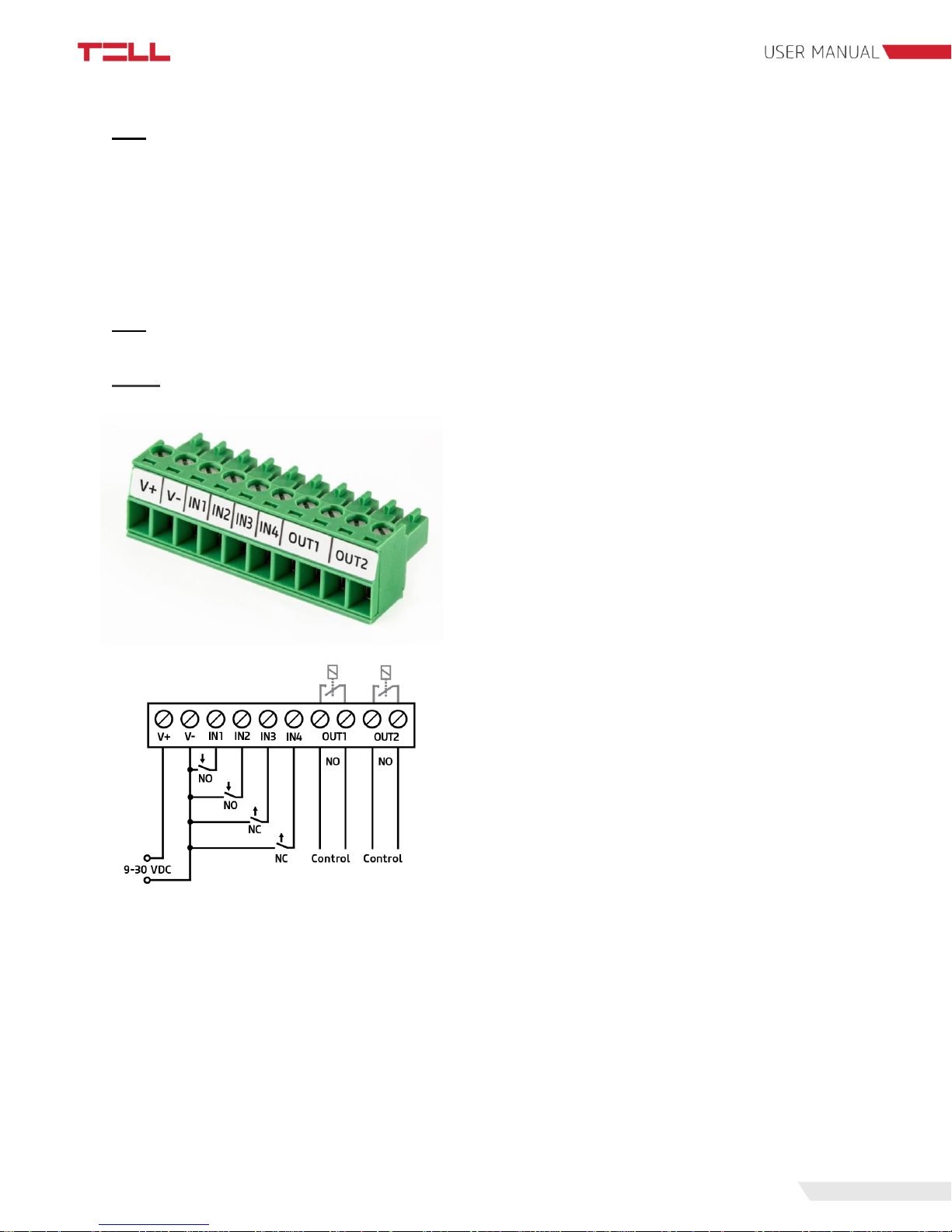
2.4.1 Wiring of Pager 7 Z4
System terminal inputs and outputs:
V+: Supply voltage 9-30V DC (min. 500 mA)
V-: Supply voltage negative polarity
IN1: 1. contact input
IN2: 2. contact input
IN3: 3. contact input
IN4: 4. contact input
OUT1: 1. normally open relay contact
OUT2: 2. normally open relay contact
In our example IN1 and IN2 inputs are normally
open (NO), while IN3 and IN4 are normally closed
(NC) inputs.
Page 10
9
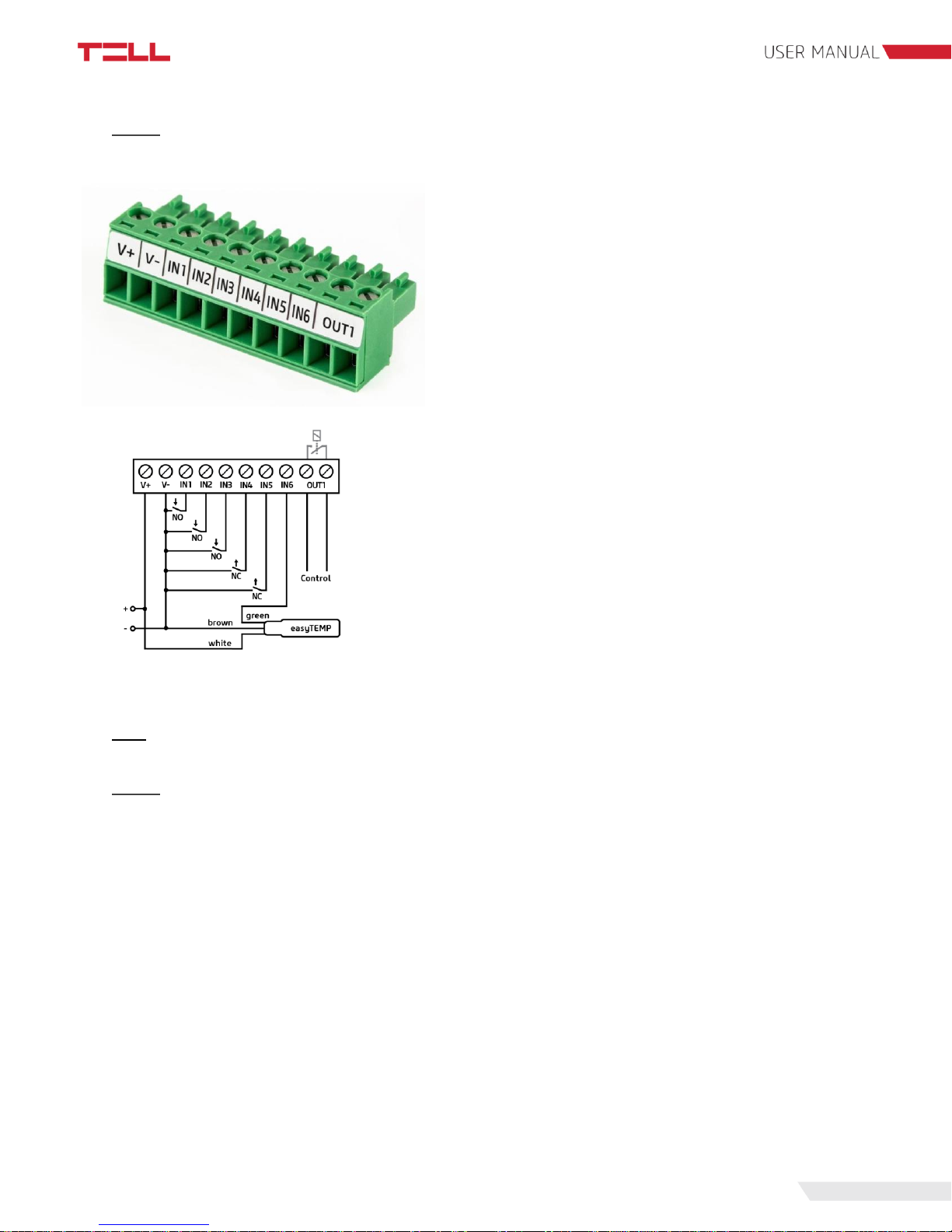
2.4.2 Wiring of Pager 7 Z6
System terminal inputs and outputs:
V+: Supply voltage 9-30V DC (min. 500 mA)
V-: Supply voltage negative polarity
IN1: 1. contact input
IN2: 2. contact input
IN3: 3. contact input
IN4: 4. contact input
IN5: 5. contact input
IN6: 6. contact input
OUT1: 1. normally open relay contact
In our example IN1, IN2 and IN3 inputs are normally open
(NO), IN4 and IN5 inputs are normally closed (NC), while
IN6 input is a temperature sensor (easyTemp).
2.5 SIM card related information
2.5.1 Selecting services
To select which services to activate on the SIM card, you need to know what features of Pager
7 you’d like to use in practice.
Several features of Pager 7 require having a mobile internet connection. A few of these features
are remote programming, remote firmware update, reporting to a monitoring station and certain
notification options like e-mail sending. In case the SIM card has no mobile internet service the
module can be programmed only through USB connection and it can send only SMS or call
notification.
To use the internet service, you need to enter the SIM card’s Access Point Name (APN) in the
programming software. You can obtain the SIM card’s public APN from your GSM provider.
APN settings are explained in detail in section 4.1.1 of this manual.
The functions that use SMS sending need SMS service and the ones that use calls require
GSM voice call service.
Page 11
10
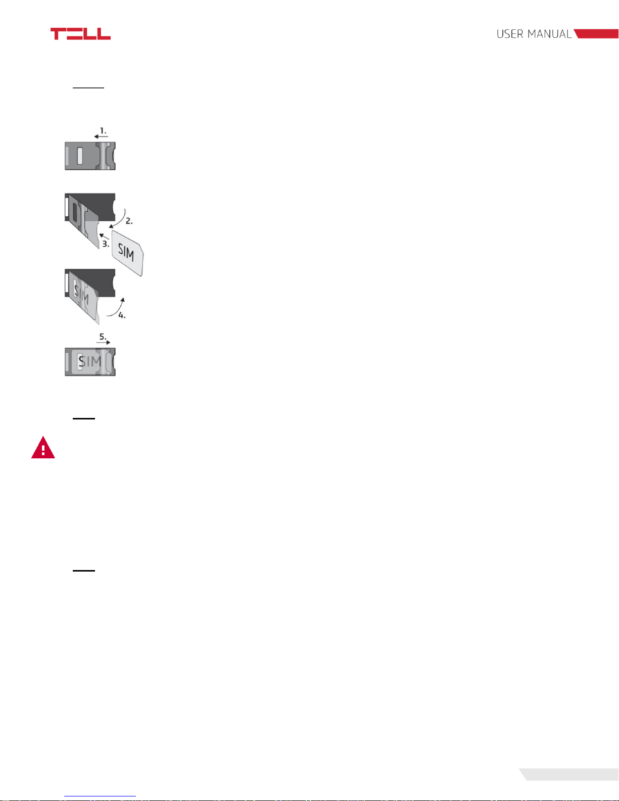
2.5.2 SIM card holder
To insert the SIM card remove the plastic cover of Pager 7 to access the SIM card case.
1. Pull the metal slider on the SIM card case towards the LED status light
until you hear the click.
2. Lift the socket as shown.
3. Insert the SIM card into the socket with its interface down.
4-5. Fold down the socket and pull back the slider to its original position until
you hear the click.
Finally replace the plastic cover.
2.6 Connecting the antenna
Attention! Do NOT connect the metallic parts of the GSM antenna connector directly or
indirectly to the protective ground, because this may damage the module!
Connect the GSM antenna to the FME-M socket. The module comes with an antenna which
provides good transmission under normal reception circumstances. In case of experiencing
signal strength problems or/and wave interference (fading), use another (directed) type of
antenna or find a more suitable mounting place for the antenna.
2.7 Installation environment
Before installing the module, verify the GSM signal strength with your mobile phone. It may
happen that the signal strength is not sufficient in the desired mounting place. In this case the
planned installation place can be changed before mounting the device.
Do not mount the unit:
● in places where it could be affected by strong electromagnetic disturbances (e.g. in the
vicinity of electric motors, high voltage, etc.)
● in wet places or places with high degree of humidity
Page 12
11
2.8 Putting into operation
● check the services provided by the SIM card (section 2.5.1)
● insert the SIM card into the module (section 2.5.2)
● connect the antenna (section 2.6)
● make the connection depending on the module version (section 2.4)
● connect the power supply (section 2.3)
2.9 LED signals
LED signal
Meaning
Yellow blinks
Booting is in progress
Green blinks
Successfully connected to the GSM network
Green blinks fast
Successfully connected to the Internet
Continuous green with rare breaks
Successfully connected to the TELL server,
normal operation
Green and red blink alternately
Alarm is in progress
Red blinks
GSM modem is starting
Continuous red
Firmware update is in progress
3. The Pager 7 programming software
The latest version of the programming software is downloadable from the
manufacturer’s website:
http://tell.hu/en/products/gprs-communicators/pager-7.
Launch the installer and follow the instructions of Setup Wizard until the
installation is complete.
3.1 User levels
Pager 7 has 2 user levels with different rights.
The admin has access to all settings and feature.
Both the admin and the user can freely configure the active desktop, have access to the module
info and camera images. The dashboard settings belong to the device, so users can have
different dashboards on each computer, tablet and mobile phone. They are allowed to record
and review camera images, switch the relays, arm/disarm the partitions and cancel the alarm.
The default admin password is: 1111
The default user password is: 2222
Page 13

12
Attention! After the first login be sure to change both the administrator and user
password.
Both passwords can be modified in the 'Module settings' module which is described in detail in
section 4.1.1 of this manual.
3.2 Logging into the programming software through USB
connection
To program Pager 7 through USB follow these steps:
● launch the Pager 7 programming software
● connect the module to the computer via USB A-B cable
● on the programming software's login screen select the USB option
● enter the password and then click the 'Connect' button
Attention! Powering from USB is not sufficient for the full functionality, however it is
enough for configuring the device!
The GSM network and the Internet access can only be assured if the proper power supply is
connected. The requirements of the power supply are described in detail in section 2.3 of this
manual.
3.3 Logging into the programming software through internet
connection
To remote programming Pager 7, mobile Internet connection is required and the module needs
to be able to access the TELL cloud server. For this, first you need to set the SIM card's access
point (APN), then the TELL server's address.
These settings can be found in section 4.1.1 of this manual.
Attention! Without setting up the access point and/or server data Pager 7 won't be
available through the Internet!
To access the module remotely we need the module's hardware ID. This can be found in the
'Module status' via USB connection.
Page 14

13
To remote programming Pager 7 through the Internet follow these steps:
● launch the Pager 7 programming software
● on the programming software's login screen select the NET CONNECTION option
● enter the hardware ID and password
● click the 'Connect' button
4. Programming the Pager 7 module
4.1 The module
After login the customizable active dashboard is displayed. For more details on editing the
active dashboard see 4.4 section of this manual. In the header, you can find the drop-down
menu icon, the TELL logo, the time and date, the module's actual GSM signal strength, the
supply voltage, the sign out icon and the language selector from the left to the right.
The TELL logo brings back to the dashboard from anywhere.
The time and date are automatically synchronized from the GSM network. If you want to
manually synchronize them from the computer, you can do so in the 'Module settings' menu.
The signal strength in the header shows the module's actual GSM signal strength. Above 60%
the GSM signal strength is sufficient, between 60-40% is low and below 40% is very low. If the
signal strength does not reach 40%, it is recommended that you try to improve the signal
strength as described in section 2.6.
For more information on power supply see section 2.3.
Each menu of Pager 7 has a built-in menu-specific help that can be accessed by clicking on the
question mark next to the title at the top of the page. To get information about the given menu
item click on the question mark icon.
Page 15

14
4.1.1 Module settings
In the 'Global settings' section, you can change the password for both access levels (admin and
user). Password length must be between 4 and 10 characters. To change a password, you
need to enter the current admin password. To confirm the changes, click the 'Save' button.
Notifications on available firmware updates will be sent to the main notification address, which is
usually the installer’s e-mail address If there's an available update, a notification link will appear
in the notification email which link will start the firmware update. The device sends an email
notification about the success of the update.
Here you can specify the exact location of the device by selecting it on the map or entering the
address. The coordinates will be automatically filled and stored during saving.
This helps the installer, so they can tell where the device is located even when they are remote
accessing it.
Page 16

15
In the 'GSM settings' section enters the PIN code to unlock the SIM card. In order to prevent the
module from reaching the PUK code after entering multiple incorrect PIN codes, there’s a builtin protection. The device tries a PIN code only once and as soon as no more PIN1 trial left,
stops trying.
In the same section, you can enter the SIM card's phone number, the daily SMS limit and the
SMS centre number. SIM card providers may require the SMS centre number for their SMS
service.
The device can also forward the incoming SMS messages. To use this feature, enter the
desired phone number on the 'Phone numbers' page and then on the 'Module settings' page,
select which phone numbers you want the incoming SMS messages to be forwarded to. For
more details on setting up the phone numbers, see 4.5.1.
The SIM card's APN can be set in the 'Access point settings' section. You can obtain the SIM
card's APN from your SIM card provider. In case the APN is not public you can also set the
username and password in this section. It is important, that certain closed APNs do not allow to
use the Internet freely, but provide access only to selected IP addresses. These closed APNs
may block the use of Pager 7 features which require Internet access.
Attention! If the access point settings are incorrect, the module's internet based services
won't be available!
The 'TELL server settings' section is for setting up the server access. In default these fields are
filled with the data of manufacturer's server reserved for this purpose, which are the followings:
Url: pager.devicemail.net
Port: 2018
If the name resolution doesn't work with your service provider replace the URL by the following
IP address: 54.75.242.103
Attention! If the server settings are incorrect, certain services of the module won't be
available!
Page 17

16
At the bottom of the 'Module settings' page you can manually refresh the system time, date and
firmware and you can also restart the Pager.
To manually update the Firmware, download the latest firmware from
https://tell.hu/en/products/gprs-communicators/pager-7 page.
Then 'Choose file' and click the 'Upload' button.
If the firmware is not compatible with the Pager 7 programming software a popup notification
appears and if you are connected via USB, the automatic firmware update is also offered.
4.1.2 Module status
The page contains the most important information about the module. The dynamic wiring
diagram is located at the top of the page. With the icons, this provides an overview of the wires
connected to the inputs even when the module is remotely accessed.
The 'Input states' section lists the inputs with their icon, name, type and state. This part is
changing dynamically as soon as the status of any input is changing.
In the 'Relay states' section the relays are listed with their icon, name and state. Like the input
status, the status of the relay is also dynamically indicated by this page.
Page 18

17
The 'Status of the partitions' section shows the name and armed/disarmed status of the
partitions.
This is followed by the supply voltage, the GSM signal strength, the module's date, time and the
time zone.
In the 'Status of the connections' section, you can check whether Pager 7 is currently connected
to the GSM network, the Internet, the TELL server and whether is a USB connection detected.
The status indicators are also dynamically changing.
The 'Pager info' section includes the device name, the device type and the hardware ID for
remote access. Information on the firmware running on the device, information on the SIM card,
the programming software's version and the GSM network related information are also in this
section. You can also find a QR code here that contains the hardware ID to help you log on from
your mobile device.
4.2 Zone settings
Inputs, relays, zones and partitions can be configured in the 'Zone settings' menu.
At the top of the page, the dynamic wiring diagram is located with the input icons set in the
'Input settings' section of this page.
Page 19

18
Input settings:
Enter the name of the input, then select its type and icon. Right after the icon is selected, the
wiring diagram above shows the selected icon.
The input type can be zone, switch, impulse switch or temperature sensor. In case of zone,
switch and impulse switch we can choose whether it is normally open (NO) or normally closed
(NC). If you don’t want to use an input, select the ’Not used’ option from the drop down list.
Attention! Do not leave unused inputs in NO or NC status as it may result false signals.
However, if the type of the unused input remains NC, it is mandatory to close it for
correct operation.
We can also set a global prell delay. This applies to all inputs and serves to filter out the
disturbances on the input. Pager 7 considers only those contacts as events, which are longer,
then the time specified here and the event-actions are executed in this case only.
Output settings:
Here you can customize the 1 or 2 outputs depending on the device version. A relay can be
bistable or monostable.
The output configured as bistable has two stable states: activated and deactivated. The bistable
relay's output status is stable, meaning that it will not change until new control. Therefore, the
delay cannot be set for a bistable relay.
If bistable mode is switched off, the relay will be monostable. The relay is normally open (NO),
so it will be stable only in deactivated state. The monostable output becomes activated if an
activation event occurs and remains activated for the time that is set in the 'Delay' field.
Page 20

19
The output’s name and icon are also customizable. Right after the icon is selected, the wiring
diagram above shows the selected icon.
Changes can be saved with the "Save" button at the bottom of the page. To cancel the
changes, you have made since the last save click the "Reset" button.
Zone settings:
You can customize the inputs defined as zone in the 'Input settings' section and assign them to
partitions (a group of zones). To use a zone, you need to enable it first. A disabled zone doesn't
generate any events, so the signals coming from a zone can be blocked by disabling the zone.
For example, in case of a possible failure, false signals coming from the zone can be eliminated
by this setting.
Attention! Zones need to be enabled in order to let the incoming contacts to generate
event operations!
You can assign zones to partitions in the same field, as well as setting up entry and exit delay
times, and 24h zones.
A 24h zone, irrespectively of arming and disarming the partitions, will always be armed.
Under entry and exit delay times that period of time is meant, in which the system does not sign
zone alarm in case of zone detection. This might be needed during arming (entry delay) and
disarming (exit delay) of the system.
Modifications can be saved with help of the ’Save’ button at the bottom of the page. To reject
the modifications done since the last save click on the ’Reset’ button.
Page 21

20
Partition configurations:
Here you can name partitions and configure whether the partition should be always armed, or
you can prevent a partition from arming as long as it has an active zone.
This can be done by choosing ’Always armed’ or ’Prevent arm on active zone’ options.
4.3 Cameras
One of the new functions of Pager 7 is that it is able to manage IP cameras, and can assign the
cameras to zones. In case of an alarm in the given zone, the images of all the cameras
previously associated with the zone are available in the application with a single click from the
alarm popup window. At this time the zone violation could even be recorded, which provides an
opportunity for later play-back.
4.3.1 Camera settings
New camera can be added by a click on ’Add camera’ button. Here the name and the image
URL of the camera picture planned to be used has to be entered.
The automatic update of the camera pictures on the dashboard and in ’View cameras’ menu
point can be set if you choose ’Automatic refresh’.
The value displayed in ’Refresh delay’ field is the time passed by between the download of the
pictures in seconds. Pager 7 starts to download the second picture following the successful
loading of the first one.
Page 22

21
Attention! Configurations regarding camera picture update will affect the camera pictures
of those cameras, which are placed on the active dashboard and in ’View cameras' menu
point only.
In case you wish to enter the video URL of the IP camera too, it is possible in the Video URL
field. This video stream, unlike snapshots will not be available within the application, but can be
opened with an external player program.
The listed cameras can be sorted by assigning them to zones. A single camera might belong to
more zones, and more cameras can be assigned to one zone. To save the modifications, click
on the ’Save’ button.
Pager 7 is able to store the settings of altogether 16 IP cameras. Deleting existing cameras is
possible by clicking on the dust-bin icon.
4.3.1.1 ONVIF camera link extraction
In case you possess an ONVIF camera and you wish to find out the link of such a camera,
please follow our manual prepared for this aim, which you can find at the bottom of the
https://tell.hu/en/products/gprs-communicators/pager-7 page among downloads.
4.3.2 View cameras
This menu point serves to look through and prepare records from the cameras, added in point
4.3.1. You can filter the cameras based on zones. If you click on the ’Select all’ button, you add
all the cameras to the filtering conditions, while ’Select none’ button clears the selection of each
zone.
Since it is not compulsory to assign a camera to a zone, cameras, not assigned to zones are
shown in the module if ’Cameras without zone’ is selected.
You can start and stop recording by a click on ’Record’ button in the own fields of certain
cameras, or by clicking on the ’Recording all’ button at the top right corner of the menu. In the
Page 23

22
previous case, only the pictures of the given camera will be recorded, while in the latter one, all
camera pictures will be recorded.
By clicking on the ’Playback’ button, you can play previous records, at this time the software
navigates us to page ’Play records’.
4.3.3 Playing records menu point
It is possible to filter among records based on date. To play the records first the date has to be
selected than the ’Play’ button has to be pressed.
4.4 Configuring active dashboard
By clicking on the ’TELL’ icon in the header or selecting the ’Dashboard’ menu point the active
dashboard can be reached anytime. The entire surface is active, which means that events and
modifications are displayed real-time on the compiled dashboard.
Some of the widgets placed on desktop are interactive. It is possible to control relays by clicking
on the widget, or change the armed status of partitions.
4.4.1 Adding widgets
You can customize the desktop with help of the red edit button in the top right corner. By
clicking on any empty square, the widget selector opens, and the top left corner of the chosen
widget will be placed in the previously chosen square. In the widget selector menu, you can
choose from many widgets in four different sizes. The size of the widget indicates how many
squares will be taken on the desktop by that certain widget.
Page 24

23
What we can add of 1x1 widgets:
● Partition: The partition, required to be added as widget has to be selected here. The
added widget is interactive – it can be armed and disarmed by a click, and shows always
the actual status of the partition. In case of an ’Always armed’ partition a lock icon will be
displayed on the widget, instead of a switch, and the system will not allow to disarm the
given partition.
● Relay: The relay, required to be added has to be selected here. The added widget is
interactive – it can be closed/opened by a click.
● Temperature sensor: The temperature sensor, required to be added has to be selected
here.
● Menu point: A frequently used menu point can be selected here and added directly to
the dashboard.
What we can add of 2x2 widgets:
● Place: This shows the place of the module, as given in ‘Module settings’ menu point.
● Zone: The zone, required to be added as widget has to be selected here. The events,
occurring on that zone will be displayed on the widget as well.
● Temperature sensor: The temperature sensor, required to be added has to be selected
here.
Page 25

24
What we can add of 4x2 widgets:
● Place: This shows the place of the module, as given in ‘Module settings’ menu point.
● Zone: The zone, required to be added as widget has to be selected here. The events,
occurring on that zone will be displayed on the widget as well, while on the right side of
the widget, the important information of the zone will be presented.
● Camera picture: The picture of an already added camera has to be selected here. The
update frequency of the camera can be configured in ‘Camera settings’ menu point, as it
is written in point 4.3.1.
What we can add of 4x4 widgets:
● Place: This shows the place of the module, as given in ‘Module settings’ menu point.
● Camera picture: The picture of an already added camera has to be selected here. The
update frequency of the camera can be configured in ‘Camera settings’ menu point, as it
is written in point 4.3.1.
4.5 Notification settings
Pager 7 is able to send notifications in several ways about the events generated on the module.
There is an option for playing voice messages via calls, sending SMS and emails. To register
these notifications channels, the following menu points can be used:
4.5.1 Phone numbers menu point
You can choose from among the here listed phone numbers in ‘Event Settings’ menu point, if
you want to assign SMS sending or phone call operations to events. It is also possible to control
the module via call with DTMF commands – the module accepts DTMF commands only from
those phone numbers, which we have previously recorded.
The module can manage altogether 8 phone numbers.
Page 26

25
Password not required: If you choose this option, calls from that given phone numbers will be
automatically authorized for control, these can control without password, via DTMF commands.
Password: This password will be required in case of incoming calls for DTMF control, if ‘No
password needed’ is not ticked in.
ACK on call success or hang up: If this option is ticked in, the incoming notification calls will
be automatically acknowledged, either the call has been accepted or rejected.
Stop other operations: In case of a call comes in as a notification to this number, the called
party can stop further operations via DTMF command, which normally would be executed. E.g.
if it is set by an event, that the module initiates call for more phone numbers, if you thick this
option in, the first number which receives the call can stop operations, therefore no calls will be
given on the further numbers.
About the applicable DTMF commands and operation of programming via calls we give further
information in point 5.1.
4.5.2 Text templates menu point
In this menu point, you can enter the texts of e-mails, SMS and PUSH notifications, which will
be sent as notifications. These schemes can be applied in ‘Event settings’ menu point by SMS,
PUSH and e-mail sending operations.
E-mail text can be entered by giving the subject and the body of the e-mail. In case of SMS and
PUSH notifications, only the text should by typed in.
16 text templates can be added by type.
4.5.3 Emails menu point
To add a new e-mail address, the e-mail address and the belonging name has to be entered.
You can choose from among the here listed e-mail addresses in the ‘Event settings’ menu point,
if you would like to assign e-mail sending notification to an event.
Altogether 8 e-mail addresses can be entered into the module.
4.5.4 Sounds menu point
You can choose from among the sounds uploaded here in ‘Event settings’ menu point, if you
would like to assign phone call operation to an event.
Attention! Uploading sounds is possible via USB connection, only!
Altogether 8 different sound file can be uploaded to the module. You can find 3, predefined
sound files in the application, if needed these can be used. Each sound file can be named. You
can upload the sounds with ‘Upload’ or ‘Upload All’ buttons from the application to the module.
Page 27

26
In case you wish to upload an own sound file, check if it meets the requirements below:
● 8Khz, Mono,16 Bit PCM
● maximum length 8 seconds
● mp3, wav, flac, qt format
You can save changes by clicking on the ‘Save’ button at the bottom of the table. You can play
the predefined notification tones by clicking on the ‘Play’ buttons at the bottom of the page.
4.5.5 Push notifications
In this menu, you can see the mobile devices which have ever been logged onto the Pager7
module, in case of receiving push notification was enabled by opening the application. You can
edit the name of the listed devices and you can also remove a device from the list. You can
choose from among the devices listed here, in the ’Event settings’ menu point, if you would like
to assign push message sending to an event.
4.6 Alarm settings menu point
You can find the settings of the alarm event in this menu point, which can be assigned to
events, as event-action in ‘Event settings’ menu point.
With the max alarm time, you can set the time period, under which the module stays in
alarmed status from the supervention of alarm. From alarmed status, by the time the
module will stay automatically back to normal status. You can assign arbitrary actions to
the change of armed status.
You can set up a restriction, regarding how many alarm event can be maximally caused in case
of zone violation. The period of restriction can be set in hours and minutes.
Changes can be saved with the ‘Save’ button at the bottom of the page.
4.7 Signalling to monitoring station
Pager 7 is able to signal customizable Contact ID codes due to certain events towards one or
more remote monitoring servers. These signals can be assigned to events in ‘Event settings’
menu point.
Page 28

27
For the transmission towards monitoring station, the remote monitoring servers have to be
configured and ordered into schemes.
4.7.1 Surveillance settings menu point
Pager 7 is able to manage two types of remote monitoring protocol, these are TELLMON and
SIA protocols.
To add a new remote monitoring station, the name of it can be freely chosen, however further
data necessary for configuration can be provided by the remote monitoring station.
Parameters have to be fulfilled in case of TELLMON and SIA protocol as well:
Client ID:
A four-character-long identifier, which is used by the remote monitoring station to identify users.
It can contain numbers and A, B, C, D, E and F letters.
Secondary Client ID:
In case of the remote monitoring station requires, a secondary Client ID needs to be given for
client identification. The minimal length of this identifier is 3, the maximal is 16 characters.
Encryption key:
If the remote monitoring station’s server is using encrypted communication, the required key has
to be entered into this field. The length of the key can be 16, 32 or 64 characters.
Keep alive frequency:
By entering the keep alive frequency, you can configure the frequency of status reports sent
towards the remote monitoring server. This number needs to be synchronized with the receiver
of the remote monitoring station.
URL:
Here you can enter the URL of the remote monitoring server.
Protocol:
Determined by the remote monitoring station, too whether it uses TCP or UDP protocol.
Page 29

28
Port:
The module communicates with the remote monitoring server via this port.
Parameters, which need to be filled in only in case of SIA protocol:
Receiver number:
This is an optional field, which server as receiver identifier at the remote monitoring station. Its
maximal length is 6 characters.
Account prefix:
This field serves for entering the maximum 6 characters long prefix of the client identifier.
Changes can be saved with help of ‘Save’ button at the bottom of the page.
4.7.2 Surveillance schemas
From the remote monitoring servers, entered in point 4.7.1 you have to create schemas in order
to make the module able to execute ‘Report action via net’ action and throughout Contact ID
transmission. Maximum 6 schemas can be created this way.
You can list maximum 6 servers in one schema. These servers are in their basic status primary
servers; you can change their status to backup by ticking in the ‘Server is backup’ option.
When you want to use the server schema for signalling, Pager 7 attempts to transmit the
Contact ID code, entered into ‘Report action via net’ action, to each primary servers. In case of
unsuccessful connection with the primary servers, it goes through the backup servers, but in this
case, stops after the first successful signal, does not attempt to reach the other backup servers.
Page 30

29
If you contracted with two or more remote monitoring companies, it is worth to configure
separate remote monitoring server schemas for each of them, with their own backup servers,
throughout ensuring the arrival of signal.
4.8 Event settings
You can assign actions to be fulfilled to forthcoming events on Pager 7 module in this menu
point. In case of certain type of events, you can add a restore event by ticking in ‘Add a reset
event’ field. Events and restore events form event pairs, which can execute both activation and
deactivation of an operation.
Event-reset event example is zone detection and deleting zone detection. In this case, if a zone
got violated, the actions belonging to that event will prevail, while if a zone got left, according to
the original event actions, but contradictory actions will be executed.
In case of actions, assigned to events have non obvious restore pairs, reset can not be
added automatically. In this case you can manually choose and set up the operations,
belonging to reset event.
Page 31

30
4.8.1 Events
Events can be listed in the following event-types:
System type events:
● Pager on: Actions, assigned to this event will be fulfilled by Pager 7 switch on.
● GSM connect: Actions, assigned to this event will be fulfilled by successful connection
to the GSM network. The restore-event pair of this event is ‘GSM disconnect’.
● GSM disconnect: Actions, assigned to this event will be fulfilled by GSM network
connection break. The restore-event pair of this event is ‘GSM connect’.
● API connect: Actions, assigned to this event will be fulfilled by successful connection to
TELL cloud server. The restore-event pair of this event is ‘API disconnect’.
● API disconnect: Actions, assigned to this event will be fulfilled by TELL cloud server
connection break. The restore-event pair of this event is ‘API connect’.
● Net connect: Actions, assigned to this event will be fulfilled by successful connection to
the internet. The restore-event pair of this event is ‘Net disconnect’.
● Net disconnect: Actions, assigned to this event will be fulfilled by internet connection
break. The restore-event pair of this event is ‘Net connect’.
● USB connect: Actions, assigned to this event will be fulfilled by USB connection to the
module. The restore-event pair of this event is ‘USB disconnect’.
● USB disconnect: Actions, assigned to this event will be fulfilled by USB disconnection.
The restore-event pair of this event is ‘USB connect’.
Page 32

31
● Test action: Actions, assigned to this event will be fulfilled by clicking on ‘Test Action
button in ‘Event settings’ menu. This is a useful tool to test the various event actions.
● Operation mode changed: Pager 7 is able to fulfill operations depending on the status
of the supply voltage on it. By adding the operation, it can be selected whether the
module should fulfil the operations, assigned to events in case of USB-, or normal supply
(9-30 V DC).
● DTMF command: Actions, assigned to this event will be fulfilled in case of incoming
DTMF command. The list of DTMF commands, managed by the module can be found in
point 5.1 of the manual.
● SMS command: Actions, assigned to this event will be fulfilled by incoming SMS
command. The list of SMS commands, managed by the module can be found in point
5.2 of the manual.
● Incoming call from unknown number: Actions, assigned to this event will be fulfilled in
case of incoming call from unknown number.
● Incoming call from trusted number: Actions, belonging to this event will be fulfilled in
case of incoming call from the given phone number. Trusted covers the numbers, added
previously in ‘Phone numbers’ menu point.
● Config segment modified: Actions, assigned to this event will be fulfilled by changing
module settings.
● Scheduled action: Actions, assigned to this event will be fulfilled at a previously defined
date. Date can be entered by choosing the event.
● Time changed: Actions, assigned to this event will be fulfilled by system time change.
● Repeating action: Actions, assigned to this event will be repeated by the here defined
frequency.
● Password change: Actions, assigned to this event will be fulfilled by admin or user
password change.
● SIM card removed: Actions, assigned to this event will be fulfilled in case the SIM card
is removed from the device.
● SIM card ready: Actions, assigned to this event will be fulfilled in case a SIM card is
inserted into the device.
● Modem firmware upgrade success: Actions assigned to this event will be fulfilled by
successfull firmware upgrade.
● Modem firmware upgrade failed: Actions, assigned to this event will be fulfilled in case
the firmware upgrade failed.
Partition type events:
● Partition arm: Actions, assigned to this event will be fulfilled by partition arming. The
partition can be chosen by adding the event. The restore-event pair of this event is
‘Partition disarm’.
● Partition disarm: Actions, assigned to this event will be fulfilled by partition disarming.
The partition can be chosen by adding the event. The restore-event pair of this event is
‘Partition arm’.
Page 33

32
Alarm type events:
● Alarm on: Actions, assigned to this event will be fulfilled by switching the alarm on. The
restore-event pair of this event is ‘Alarm off’.
● Alarm off: Actions, assigned to this event will be fulfilled by switching the alarm off. The
restore-event pair of this event is ‘Alarm switch on’.
Zone type events:
● Zone detect: Actions, assigned to this event will be fulfilled by zone breach. The zone
can be selected by adding the event. The restore-event pair of this event is ‘Zone detect
release’.
● Zone detect release: Actions, assigned to this event will be fulfilled by zone breach
ceasing. The zone can be selected by adding the event. The restore-event pair of this
event is ‘Zone detect’.
Sensor type events:
● Voltage limit over: Actions, assigned to this event will be fulfilled by supply voltage
raising above a certain threshold limit. Threshold limit can be entered by adding the
event. The restore-event pair of this event is ‘Voltage limit under’.
● Voltage limit under: Actions, assigned to this event will be fulfilled by supply voltage
decrease under a certain threshold limit. Threshold limit can be entered by adding the
event. The restore-event pair of this event is ‘Voltage limit over’.
● Temperature sensor limit over: Actions, assigned to this event will be fulfilled by
temperature raising above a certain threshold limit. Temperature sensor and threshold
limit can be chosen by adding the event. The restore-event pair of this event is
‘Temperature sensor limit under’.
● Temperature sensor limit under: Actions, assigned to this event will be fulfilled by
temperature decrease under a certain threshold limit. Temperature sensor and threshold
limit can be chosen by adding the event. The restore-event pair of this event is
‘Temperature sensor limit over’.
● Temperature sensor lost: Actions, assigned to this event will be fulfilled by ceasing
temperature sensor signals. The temperature sensor can be chosen by adding the
event. The restore-event pair of this event is ‘Temperature sensor restored’.
● Temperature sensor restored: Actions, assigned to this event will be fulfilled by
restoring temperature sensor signals. The temperature sensor can be chosen by adding
the event. The restore-event pair of this event is ‘Temperature sensor lost’.
Page 34

33
Switch type events:
● Switch On: Actions, assigned to this event will be fulfilled by switching contact on. From
among the contact type inputs you can choose by adding the event. The restore-event
pair of this event is ‘Switch off’.
● Switch Off: Actions, assigned to this event will be fulfilled by switching contact off. From
among the contact type inputs you can choose by adding the event. The restore-event
pair of this event is ‘Switch on’.
● Switch Impulse: Actions, assigned to this event will be fulfilled by incoming impulse via
impulse type inputs. You can choose from among the impulse switch type inputs by
adding the event.
Relay type events:
● Relay close: Actions, assigned to this event will be fulfilled by relay tightening. The relay
can be chosen by adding the event. The restore-event pair of this event is ‘Relay open’.
● Relay open: Actions, assigned to this event will be fulfilled by relay loosing. The relay
can be chosen by adding the event. The restore-event pair of this event is ‘Relay close’.
4.8.2 Actions
You can assign any number of the following actions to the chosen events in point 4.8. The
system is able to manage altogether 100 event-action pairs:
Page 35

34
Send SMS:
You can send in ‘Text templates’ menu point predefined texts in SMS to one of the phone
numbers, added to ‘Phone numbers’ menu point. You can also add new text or phone number
by operation settings, with a click on the appropriate button. These phone numbers and texts
will be saved automatically, and will be available later in ‘Phone numbers’ and ‘Text templates’
menus.
Send email:
You can send a predefined text in e-mail, as set in ‘Text templates’ menu to one of the e-mail
addresses, entered into ‘Emails’ menu point. You can also add new text or e-mail address by
clicking on the appropriate button. These e-mail addresses and texts will be saved
automatically, and will be available later in ‘Emails’ and ‘Text templates’ menus.
Make call:
You can send a tone file set in ‘Sounds’ menu to one of those phone numbers, entered in
‘Phone numbers’ menu point. In this case phone call plays a tone file. You can add new phone
numbers by clicking on the appropriate button, when setting up the operation. These numbers
will be saved automatically, and will be available later in ‘Phone numbers’ menu.
Report action via net:
The module is able to send Contact ID code to one of the schemes added into ‘Surveillance
schemas’. You can enter the CID code by adding the event.
Relay close:
This action closes the selected relay. By adding the action, you have to choose the relay or
relays, wished to get closed. The opposite of this action is ’Relay open’ action.
Relay open:
This action opens the selected relay. By adding the action, you have to choose the relay or
relays, wished to get opened. The opposite of this action is ’Relay close’ action.
Arm:
The action arms the chosen partition. By adding the operation, you have to choose the partition
or partitions, wished to get armed. The opposite of this action is ‘Disarming’ action.
Disarm:
The action disarms the chosen partition. By adding the action, you have to choose the partition
or partitions, wished to get disarmed. The opposite of this action is ‘Arming’ action.
Page 36

35
Toggle arm:
Depending on the status of the partition or partitions, the module fulfills arming or disarming
action. By adding the action, the partition or partitions have to be chosen, which are requested
to get armed or disarmed.
Alarm:
The action starts the alarm. The opposite of this action is ‘Stopping alarm’.
Clear alarm:
The action stops the alarm. The opposite of this operation is ‘Alarm’.
Push notification:
You can send Push message to one of the mobile devices, listed in ’Push notifications’ menu
point. The message can be selected from the texts added in ’Text templates’ menu or you can
also add new text by clicking on the ’Add’ button.
Attention! If the action has a restore-pair, and ‘Add a reset event’ option is switched on,
the event assigns the opposite action of the original action (e.g. arming-disarming)! In
case the action doesn’t have a restore action, the ’Add a reset event’ option is not
available.
Operation priority:
You can assign more actions to one event, which will be fulfilled as per priority level. The order
of the same priority actions can be changed after the first adding and saving of the event. The
‘Immediate’ priority actions will be fulfilled out of turn, while ‘High’ and ‘Low’ priority actions will
be listed among the actions, waiting for fulfilment, and will be fulfilled according to their priority.
High priority actions are usually the ones which require GSM network, but can be fulfilled
quickly, while the time-consuming actions have lower priority (e.g.: a phone call).
4.8.3 Presets
The predefined event-action schemas help by adding frequently used events and their actions.
This is for instance ‘Report zone detects’ and ‘Alarm on zone detect’ presets.
Page 37

36
4.9 Log, configuration and debug
4.9.1 Log menu point
The events occurred on Pager 7 module are displayed in a tabular form. The module is able to
store 1000 events altogether. In case of the number of events would increase above 1000, the
oldest events will be replaced. In the chart you can find information about the time when the
event occurred, its name, two parameters and the fulfilment status of the actions. In the event
parameters you can find for example the input and relay IDs, sensor data and information
regarding module status.
With help of the arrows, at the top of the chart you can switch among the pages, jump to the
beginning or the end of the log. By typing in the number of the required page into the field
between the arrows, you can jump to the given page. By clicking on the button at the top right
corner of the chart you can reload the list.
Page 38

37
You can get information about the operations, belonging to the events with help of the
downward arrow next to the serial number of the events.
4.9.2 Configuration menu point
You have more options regarding the configuration saving. Every element of the configuration
will be saved by default, however by clicking on the arrow next to ‘Select all’ caption, the
configuration to be saved can be customized by choosing its various elements. You can save
the configuration by clicking on ‘Save’ button after entering a filename.
An already existing configuration can be loaded also from file, this time you have to choose the
appropriate configuration file from computer, then click on ‘Load’ button. As an extra function,
you can modify the chosen configuration before loading, by clicking on the edit icon.
Attention! This function requires competence and high expertise!
4.9.3 Debug information
The chart, containing the time, category and parameters of debug information can be reached in
‘Debug information’ menu point. This menu point is mostly useful by troubleshooting, and with
help of this you can have exact information about the operation of the module. By switching on
and off the criteria above the chart you can filter data. This way filtered data can be saved in
CSV format on computer, by clicking on ‘Export debug information’ button.
Page 39

38
5. Alternative programming options
A small proportion of programing Pager 7 can be done without internet connection or
application, via GSM call, DTMF commands. Besides this, with DTMF commands you have an
option for certain module status query, acknowledgement of outgoing calls, pausing operations
after call notifications.
Attention! These functions are available only, if the SIM card in the module supports
making and answering calls.
5.1 DTMF commands
DTMF commands in case of incoming calls:
*PWD#
Module password entering for authentication. ‘PWD’ has to be replaced with the
password.
*0P#
Partition disarming. ‘P’ has to be replaced with the number of partition wished to be
disarmed (e.g.: *01#).
*1P#
Partition arming. ‘P’ has to be replaced with the number of partition wished to be
armed (e.g.: *12#).
*2P#
Partition status query. ‘P’ has to be replaced with the number of partition (e.g.:
*21#).
*3RS#
Relay status setup. ‘R’ has to be replaced with the number of the relay wished to be
controlled, while ‘S’ has to be replaced with 1 if you want to close, 0 if you want to
open the relay (e.g. *321#).
*3R#
Relay status query. ‘R’ has to be replaced with the number of the relay wanted to
have a query on. (e.g.: *31#).
DTMF command in case of outgoing calls:
*
Phone notification acknowledgement.
#
Stopping further operations. If you stop the operation with this command, the
further phone numbers set up will not be called by the module.
The module gives feedback through the line about the successful fulfilment of the commands,
and answers status query this way, too. The meaning of three short beep after giving out the
command is ‘successful operation’, while in case of status query, ‘switched on status’. The
meaning of a long beep after giving out the command is ‘unsuccessful operation’, in case of
status query, ‘switched off status’.
Page 40

39
5.2 SMS commands
Command in case of incoming SMS:
*PWD=jelszó#
Module password entering for authentication. ‘PWD’ has to be
replaced with the password, added by entering a phone number.
*HWID#
Hardware ID query from module.
*APN=NAME,[USER],
[PASSWORD]#
Setting up the module APN. ‘NAME has to be replaced with access
point name, while ‘USER’ and ‘PASSWORD’ has to be replaced
with the user name and password belonging to that access point
(e.g.: *APN=internet,[installer],[appletree]# ). User and password
are optional, in case of public APN, it is not necessary to be
entered.
*PX=0#
Partition disarming. ‘X’ has to be replaced with the number of
partition, wished to be disarmed (e.g.: *P1=0#).
*PX=1#
Partition arming. ‘X’ has to be replaced with the number of partition,
wished to be armed (e.g.: *P2=1#).
*RX=Y#
Relay status setting in bistabil mode. ‘X’ has to be replaced with the
number of the relay, wished to be controlled, while ‘Y’ has to be
replaced with 1 if you wish to close and 0 if you wish to open the
relay (e.g.: *R1=1#).
*RX=1Z#
Relay status setting in monostabil mode. ‘X’ has to be replaced with
the number of the relay, wished to be controlled, while ‘Z’ has to be
filled up with the time period in seconds, in which the relay wished
to stay closed (e.g.: *R1=130#).
*STATUS#
Status report query from module. You will receive a similar list in a
reply SMS:
STATUS: U=12.21; S=-72dBm (56%); P1: 1; P2: 0; Z1: 1; Z2: 1; T3:
25; I4: N/A; R1: 1; R2: 0; TIME (UTC): 2017-01-01 12:00:00;
Here, U is voltage, S is field strength, P1-P2 are partitions, Z1-Z2
are zone-defined inputs, T3 is a temperature sensor input, I4 is an
undefined input, R1-R2 show relay status. Besides this, the module
time can be read as well.
*REBOOT#
Module reboot.
*XXX, CRQ#
Rely SMS query about the fulfilment of the above command. ‘XXX’
has to be replaced with that command, about which you want to
receive the reply SMS (e.g.: *R1=1#, CRQ#).
You can send more commands in one SMS, these commands have to be written without space
in an SMS after each other, * and # have separating function, framing the command.
Page 41

40
www.tell.hu
Document version: 1.0 – 31.08.2017
 Loading...