

tell Pager4, Pager4 2G.IN4.R2, Pager4 PRO, Pager4 2G.IN6.R1, Pager4 3G.IN4.R2 Installation And User Manual
...Page 1
Pager4
Pager4 PRO
INSTALLATION AND USER MANUAL
for device version v5.00 and newer
Document version: 5.00 10.08.2018
Product models:
Pager4 2G.IN4.R2
Pager4 2G.IN6.R1
Pager4 3G.IN4.R2
Pager4 3G.IN6.R1
Pager4 3GA.IN4.R2
Pager4 3GA.IN6.R1
Pager4 PRO 2G.IN4.R2
Pager4 PRO 2G.IN6.R1
Pager4 PRO 3G.IN4.R2
Pager4 PRO 3G.IN6.R1
Pager4 PRO 3GA.IN4.R2
Pager4 PRO 3GA.IN6.R1
Page 2

2
Table of contents
1 Main functions of the product ........................................................................................................ 3
1.1 Differences between the Pager4 and the Pager4 PRO models ............................................ 3
1.2 Differences between the 2G, 3G and 3GA models ............................................................... 4
1.3 Differences between the IN4.R2 and the IN6.R1 models ...................................................... 4
2 Connecting the terminals and putting into operation ..................................................................... 4
2.1 Under Voltage Lock Out (UVLO) function ............................................................................. 4
2.2 Input wiring ........................................................................................................................... 5
2.3 Output wiring ......................................................................................................................... 5
2.4 Connections and wiring (IN4.R2 model) ............................................................................... 5
2.5 Connections and wiring (IN6.R1 model) ............................................................................... 6
2.6 SIM card socket .................................................................................................................... 6
2.7 Connecting the antenna ........................................................................................................ 7
2.8 LED indicator ........................................................................................................................ 7
2.9 Installation ............................................................................................................................. 7
2.10 Putting into operation ............................................................................................................ 7
2.11 Technical specification ................................................................ .......................................... 8
3 General information on the notification process ............................................................................ 8
4 Configuring the Pager4 ................................................................................................................. 9
4.1 The user interface and configuration options of the software ................................................ 9
4.2 Methods of connecting to the device ..................................................................................... 9
4.2.1 Configuring directly via USB ....................................................................................... 10
4.2.2 Remote connecting to devices via cloud service ........................................................ 11
4.2.3 Remote connecting to devices via peer-to-peer connection ....................................... 14
4.2.4 Remote connecting to devices which are using the TEX-MVP protocol ..................... 15
4.2.5 Remote connecting to devices which are using the TELLMon protocol ..................... 16
5 How to use the Pager4 programming software ........................................................................... 17
5.1 Connection menu ................................................................................................................ 17
5.1.1 Viewing the settings options and configuring offline ................................................... 17
5.1.2 Connection type ......................................................................................................... 18
5.1.3 Device register ........................................................................................................... 19
5.2 Device settings menu .......................................................................................................... 21
5.2.1 General ....................................................................................................................... 21
5.2.2 Mobile devices (Pager4 PRO only)............................................................................. 26
5.2.3 Reporting channels..................................................................................................... 28
5.2.4 Notification templates ................................................................................................. 31
5.2.5 Inputs .......................................................................................................................... 33
5.2.6 Input events ................................ ................................ ................................ ................ 35
5.2.7 Service events ............................................................................................................ 39
5.2.8 IP cameras (Pager4 PRO only) .................................................................................. 44
5.2.9 Voice messages ......................................................................................................... 46
5.2.10 Advanced settings ...................................................................................................... 48
5.3 Device status menu ............................................................................................................ 50
5.3.1 Status monitoring........................................................................................................ 50
5.3.2 Event monitoring......................................................................................................... 53
5.3.3 System logs ................................................................................................................ 55
5.4 Software settings menu ...................................................................................................... 57
5.4.1 Settings ...................................................................................................................... 57
5.4.2 About .......................................................................................................................... 58
6 Controlling the device remotely by DTMF commands and text message .................................... 59
6.1 Remote control and status query by DTMF commands via phone call ............................... 59
6.2 Remote control and status query by SMS ........................................................................... 60
7 Factory reset ............................................................................................................................... 62
8 Contents of the package ............................................................................................................. 62
9 About the manufacturer ............................................................................................................... 62
Page 3

3
1 Main functions of the product
The device can be used as an accessory for alarm control panels, as an individual
GSM transmitter, or as a 4/6 zone standalone alarm control device with arming/disarming option.
Main functions:
Sends SMS, e-mail* and Push notification* with configurable message for each event
Reports events by SMS, e-mail* and Push notification*, by voice call with recordable
message, over IP to remote monitoring stations using different communication protocols
and by voice call using DTMF-based Contact ID protocol.
Reporting options:
SMS with configurable message up to 10 phone numbers
E-mail with configurable message up to 4 addresses*
Push notification with configurable message up to 4 users (mobile applications)*
Voice call up to 10 phone numbers with up to 15 uploadable or recordable
messages of 10 seconds each
Reporting to CMS (Central monitoring station) over IP up to 4 IP addresses using
SIA IP DC-09, TELLMon and TEX protocol
Reporting to CMS by voice call using DTMF-based (DC-05) Contact ID protocol up
to 2 phone numbers
Up to 10 notification templates can be created and assigned to events in order to configure
the priorities of reporting channels used for reporting to CMS
Configurable Contact ID event codes for each event including partition and zone options
Output control can be customized separately for each event using different operation
modes
Available events: input events, service/error events (new and restore as well)
Local arming and disarming using dry contacts on inputs (with optional keyswitch, RF
remote controller or access control keypad with relay output)
Remote arming and disarming, status query and output control by phone call and SMS, as
well as through the Internet using the mobile application*
IP camera support: forwarding the links of up to 4 IP cameras by e-mail and Push
notification along with the alarm messages
* available in the PRO model only
1.1 Differences between the Pager4 and the Pager4 PRO models
There are differences in function between the Pager4 and the Pager4 PRO product models.
The Pager4 PRO includes the following extra functions:
E-mail notification
Push notification
TELL Control Center multiplatform mobile application (iOS and Android)
IP camera support
Page 4
4
1.2 Differences between the 2G, 3G and 3GA models
The only difference between the 2G and 3G models is the type of the modem used.
The 3G (UMTS) communication makes possible higher speed, thereby increasing the speed of
reporting. The 2G and 3G models can be used in Europe, while the 3GA model is equipped with
a pentaband UMTS/HSPA modem that can be used worldwide. There is no difference between
the mentioned models with regard to the available functions or configuration.
For the 2G model, calls made through the GSM network will delay all other communication,
since 2G modems are unable to use multiple communication channels simultaneously.
1.3 Differences between the IN4.R2 and the IN6.R1 models
The IN4.R2 model comes with 4 contact inputs (IN1 to IN4) and 2 relay outputs (OUT1, OUT2),
while the IN6.R1 has 6 contact inputs (IN1 to IN6) and 1 relay output (OUT1).
2 Connecting the terminals and putting into operation
Attention! Do NOT connect the metallic parts of the GSM antenna connector or the
terminals of the device directly or indirectly to the protective ground, because this may
damage the device!
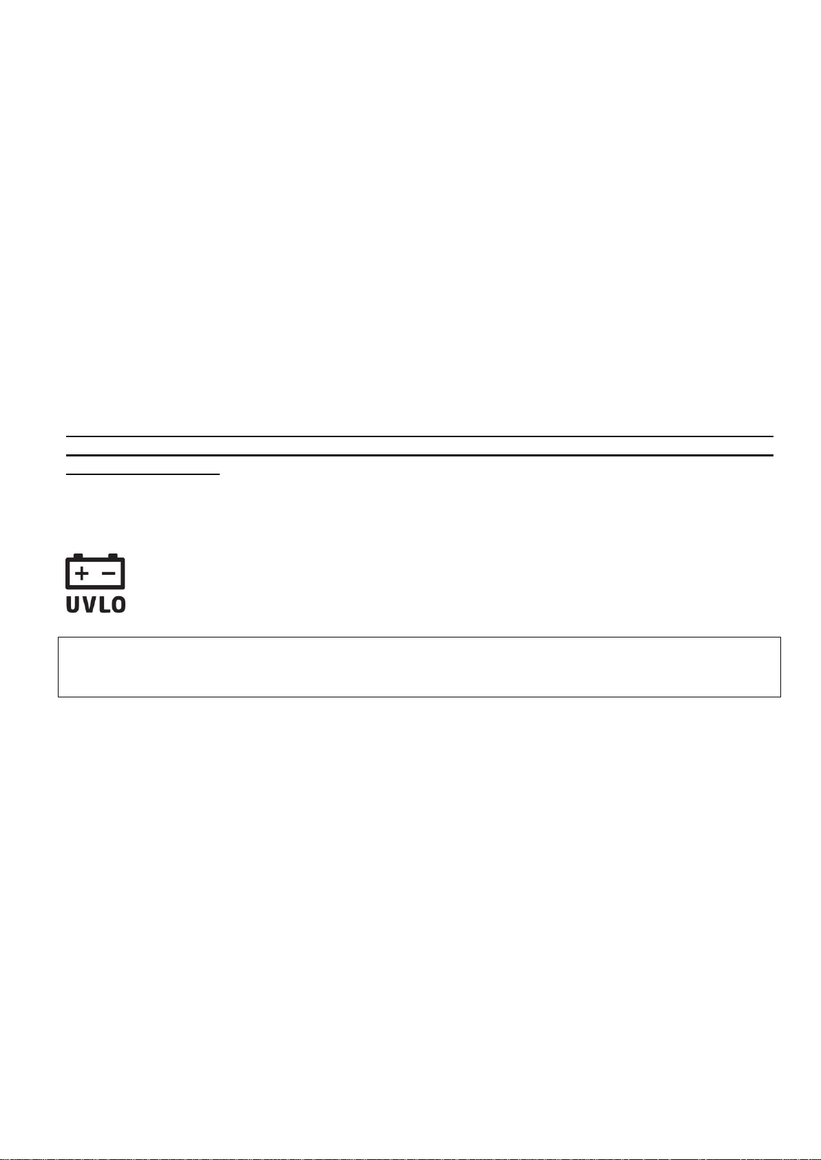
2.1 Under Voltage Lock Out (UVLO) function
The product is provided with built-in automatic power disconnection (Under Voltage
Lock Out) function. Depending on the product type, if the supply voltage drops below
8.4…8.2V, the device turns off automatically and it turns back on when the supply
voltage is at least 11.2…11.4V.
The minimum supply voltage level required to turn the device on is 11.2…11.4V!
After turned on with supply voltage higher than 11.2…11.4V, the device can operate
stably even at lower supply voltage, but not lower than 8.4…8.2V.
If the device is powered from a power supply provided with a backup battery and there is no
other electrical load on the battery when charging fails (e.g. in case of a power cut), while the
battery discharges, the device turns off automatically at 8.4…8.2V voltage level.
Thereafter, if the battery is in good condition, it can regenerate and can reach the terminal
voltage of 11.2…11.4V where the device turns back on, then the battery may discharge again
below 8.4…8.2V. This may result a continuous switching on and off cycle that lasts until the
battery can no longer regenerate to the 11.2…11.4V voltage level. If this phenomenon occurs,
the battery is flat and it should be replaced.
Page 5
5
2.2 Input wiring
For the inputs, the normally closed or normally open dry contact should be connected between
the given input (IN1…IN4/IN6) and the negative of the power input (V-) terminal.
If a normally open dry contact is used to activate the input, choose the NO (normally open)
option at the given input’s settings. In this case the input becomes activated when the given
input (IN1…IN4/IN6) and the V- terminal is shorted.
If a normally closed dry contact is used to activate the input, choose the NC (normally closed)
option at the given input’s settings. In this case the input becomes activated when shorting
between the given input (IN1…IN4/IN6) and the V- terminal is removed.
2.3 Output wiring
The output provides normally open (N.O.) dry (potential free) relay contact by default and closed
contact upon control.
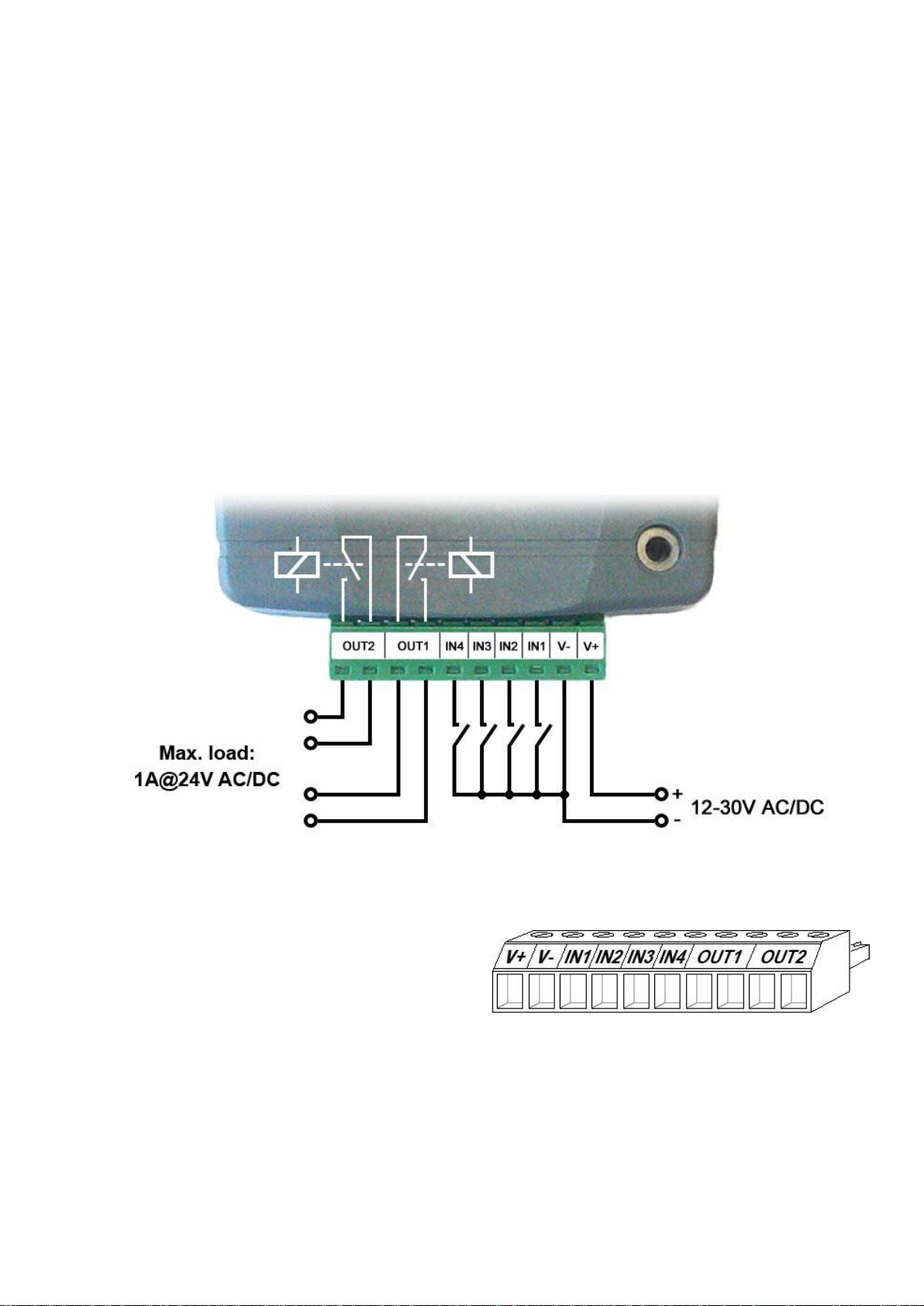
2.4 Connections and wiring (IN4.R2 model)
System terminal inputs and outputs:
V+ Supply voltage ~ / 12…30V AC/DC (min. 500 mA)
V- Supply voltage ~ / negative (if DC)
IN1 Dry contact input 1
IN2 Dry contact input 2
IN3 Dry contact input 3
IN4 Dry contact input 4
OUT1 Relay output 1 (normally open dry contact)
OUT2 Relay output 2 (normally open dry contact)
Page 6
6
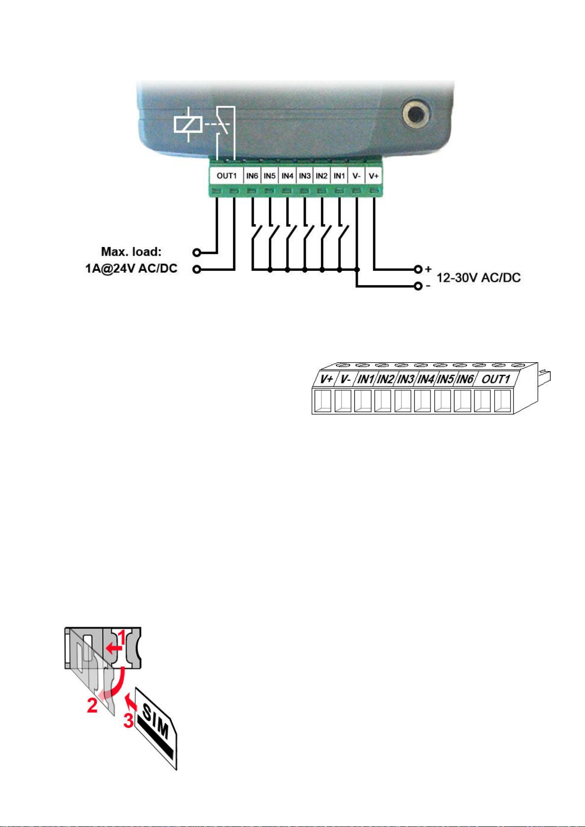
2.5 Connections and wiring (IN6.R1 model)
System terminal inputs and outputs:
V+ Supply voltage ~ / 12…30V AC/DC (min. 500 mA)
V- Supply voltage ~ / negative (for DC)
IN1 Dry contact input 1
IN2 Dry contact input 2
IN3 Dry contact input 3
IN4 Dry contact input 4
IN5 Dry contact input 5
IN6 Dry contact input 6
OUT1 Relay output (normally open dry contact)
2.6 SIM card socket
The SIM card socket can be accessed by removing the cover of the aperture found on the
device enclosure. The cover can be removed by pressing it with your fingernail towards the LED
at the end where the gap is and then pulling it outwards. Insert the SIM card in the socket. The
services to be activated on the SIM card installed into the device should be chosen according to
which services of the device you wish to use. Basically, for communication with receivers and
servers it requires a SIM card with mobile Internet access that may use either public or private
APN. The functions that use SMS sending need SMS service and the ones that use calls require
GSM voice call service.
Installing the SIM card:
1. pull the metal security lock of the SIM socket towards the
LED until it clicks
2. reach under the metallic security lock with your fingernail
and pull it outwards to open the socket
3. slide the SIM card into the opened part with the contacts
facing down, as shown in the figure
Close back the opened part together with the SIM card.
Press down carefully the metallic security lock and pull it
towards the side of the enclosure until it clicks.
Page 7

7
2.7 Connecting the antenna
Connect the GSM antenna to the FME-M socket. The device comes with an antenna which
provides good transmission under normal reception circumstances. In case of experiencing
signal strength problems or/and wave interference (fading), use another (directed) type of
antenna or find a more suitable mounting place for the antenna. In case of installing the unit into
a metal box, the antenna should be mounted outside the box in a place where the measured
GSM signal is the highest available.
2.8 LED indicator
Blinking red
The GSM service is unavailable
or system startup/restart is in progress
Permanent red
SIM card error
Red blinks fast
Green blinks slower
Event reporting is in progress
Green blinks slowly,
Red is not lit
Connected to the GSM network,
device disarmed
Green and red blink alternately
Connected to the GSM network,
device armed
2.9 Installation
Please check the environment before installing:
Verify the GSM signal strength with your mobile phone. It may happen that the signal
strength is not sufficient in the desired mounting place. In this case the planned installation
place can be changed before mounting the device.
Do not mount the unit in places where it could be affected by strong electromagnetic
disturbances (e.g. close to electric motors, high voltage, etc.).
Do not mount the unit in wet places or places with high degree of humidity.
2.10 Putting into operation
Disable voicemail and notification in SMS about missed calls on the SIM card
installed into the device.
The device can handle the SIM card’s PIN code. If you wish to use the
PIN code management, configure the SIM card’s PIN code in the programming
software at the “Settings” section. Otherwise disable PIN code request on the SIM
card.
Enable both caller identification and caller ID presentation (CLIP) service on the SIM
card at the GSM service provider (these services might not be enabled by default, please
check). To enable these services, install the SIM card into a mobile phone and call the
customer service of the card’s GSM service provider and enable the services in the menu,
or visit one of the service provider’s personal customer services and ask to enable these
services on the SIM card.
Check the SIM card to be installed correctly into the device.
Check the GSM antenna to be connected correctly to the device.
Check the wires to be connected as instructed in the wiring diagram.
You can power up the device (12…30V AC/DC). Make sure that the power source satisfy
the consumption of the device. The quiescent current of the device is 120mA, however it
may increase up to 500mA during communication and relay control. If the used power
source is not sufficient for the operation of the device, this may cause malfunctions.
Page 8

8
2.11 Technical specification
Supply voltage range: 12…30V AC/DC
Nominal current consumption: 120mA
Highest current consumption: 500mA @ 12V DC, 250mA @ 24V DC
Operating temperature: -20ºC to +70ºC
Transmission frequency: 2G model: 850/900/1800/1900 MHz
3G model: 900/2100 MHz @UMTS, 900/1800 MHz @GSM
3GA model: 800/850/900/1900/2100 MHz @UMTS
850/900/1800/1900 MHz @GSM
Highest load supported on outputs: 1A @ 24VAC/DC
Modem type: 2G model: Quectel M95
3G model: Quectel UG95
3GA model: Quectel UG96
Dimensions: 84 x 72 x 32mm
Weight: 200g (packed: 300g)
3 General information on the notification process
Notifications are performed based on the events available in the device. Each event can be
configured to send report to CMS over IP or DTMF-based voice call, as well as to send
notifications to users by call or SMS. There are 2 groups of events available in the device: input
events and service events. An input event is generated when an input is activated, but only if the
device is armed or the given input is configured as a 24h zone. Non-24h inputs will not generate
events when the device is disarmed. Service events are generated and can send notifications
also when the device is disarmed. Service events are such as arming, disarming, error events,
periodic test report.
When an event is generated, the device starts sending the configured notifications.
The priority of notification is the following: CMS, SMS, calls.
The number of attempts for reporting to CMS have a separate logic, since reporting to CMS is
based on notification templates. You can read more about this in the “Notification templates”
paragraph. Regarding text message sending and calls, the device makes 3 attempts to send a
message and 3 attempts to make a call to a user phone number. The device will no longer try to
report events for which reporting failed for more than 24 hours.
Page 9
9
4 Configuring the Pager4
The device can be configured the following ways:
By computer via USB, using the programming software.
By computer over the Internet, using the programming software.
The Pager4 programming software is compatible with the following operating systems:
Windows 10 (32/64 bit)
Windows 8.x (32/64 bit)
Windows 7 (32/64 bit)
Installing the programming software: open the software setup application and follow the
instructions of the installation wizard to complete the installation. The latest version of the
programming software can be downloaded from the manufacturer’s website (http://www.tell.hu).
The Pager4 programming software can be used to configure all Pager4 device models.
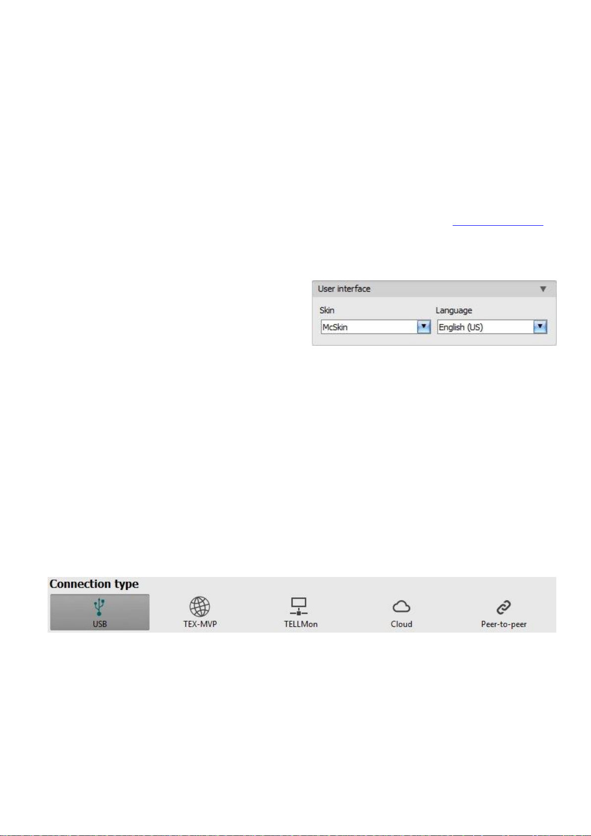
4.1 The user interface and configuration options of the software
The user interface language can be selected
from the “Language” selection drop-down menu
found in the “Software settings” / “Settings”
menu.
The user interface skin can be changed using
the “Skin” dropdown-menu found in the “Software settings” / “Settings” menu, where you can
choose out of multiple appearance themes.
Context-sensitive help:
The “Help” section on the right hand side of the program window opens a context-sensitive help
by dragging the mouse pointer above it. You can pin the help window thus making it always
visible by clicking on the “thumbtack” icon in the top right corner of the window. If you click on
any of the settings fields within the program window, you will get brief information about the
given option or setting in the help window. The content of the help window can be scrolled up
and down using the scrollbar placed on the right hand side of the help window, or using the
mouse wheel after clicking inside the help window. For better readability, the help window can
be resized by dragging the left-side border of the window horizontally using the mouse.
The software saves changes related to appearance upon closing and applies the saved settings
when reopened.
4.2 Methods of connecting to the device
For connecting to the device using the programming software, the following options are
available:
USB: direct connection using a USB A-B cable.
TEX-MVP: remote connection through the Internet via the TEX-MVP server. This option can be
used by central monitoring stations that own a TEX-MVP server.
TELLMon: remote connection through the Internet via the TELLMon receiver. This option can be
used by central monitoring stations that own a TELLMon receiver.
Cloud: remote connection through the Internet via the cloud server operated by the
manufacturer.
Page 10

10
Peer-to-peer: direct remote connection via the Internet. This option can be used if the computer
running the programming software and the SIM card installed into the Pager4 device are in the
same VPN or a private APN.
4.2.1 Configuring directly via USB
To start programming the device, follow the instructions below:
Open the Pager4 programming software.
Select the USB option in the “Connection type” menu, power up the device and connect it
to the computer using a USB A-B cable.
Enter the connection password.
o Super administrator permission: full access to all settings. (Default password: 1234).
o Administrator permission: full access to all settings except device identification settings.
o Connecting without password: only restoring the factory default settings is available, if
the device has not been locked.
Click on the “Connect” button.
If the wrong password is entered, the software connects to the device, but the same
functions will be available as when connecting without a password. To try a different
password, close the connection using the “Disconnect” button, enter the new
password and then connect again using the “Connect” button.
The software connects to the device using standard HID driver which is integrated in
Windows operating systems, thus there is no need to install special USB drivers. When the
device is connected to USB for the very first time, the Windows operating system installs
the drivers automatically.
The connection status is indicated by the USB status icon placed in the upper left corner of
the program window:
USB disconnected (green)
connected via USB (grey)
After connecting using the valid password, you can configure the device, change settings,
download event logs, monitor system status and perform controls.
To close the connection, click on “Disconnect” button.
Page 11
11
4.2.2 Remote connecting to devices via cloud service
This connection type can be used if the Pager4 device you wish to connect remotely to,
can use the cloud service. For this, the APN settings should be configured in the
“General” settings menu and it is also necessary to have installed into the device a SIM
card with available mobile Internet service which uses public APN, or, if using a private
APN, accessing the cloud server IP address should be enabled in the given APN.
If the “Cloud usage” option is enabled and the cloud server availabilities are configured in the
same menu, the device will be continuously online, so it can be accessed at anytime via the
cloud server. Otherwise it will only connect upon request sent by SMS, as mentioned below.
With this connection type, connection between the device and the Pager4 programming
software will be established through the cloud server operated by the manufacturer.
The “System logs” option of the programming software cannot be used in case of remote
connection over the Internet.
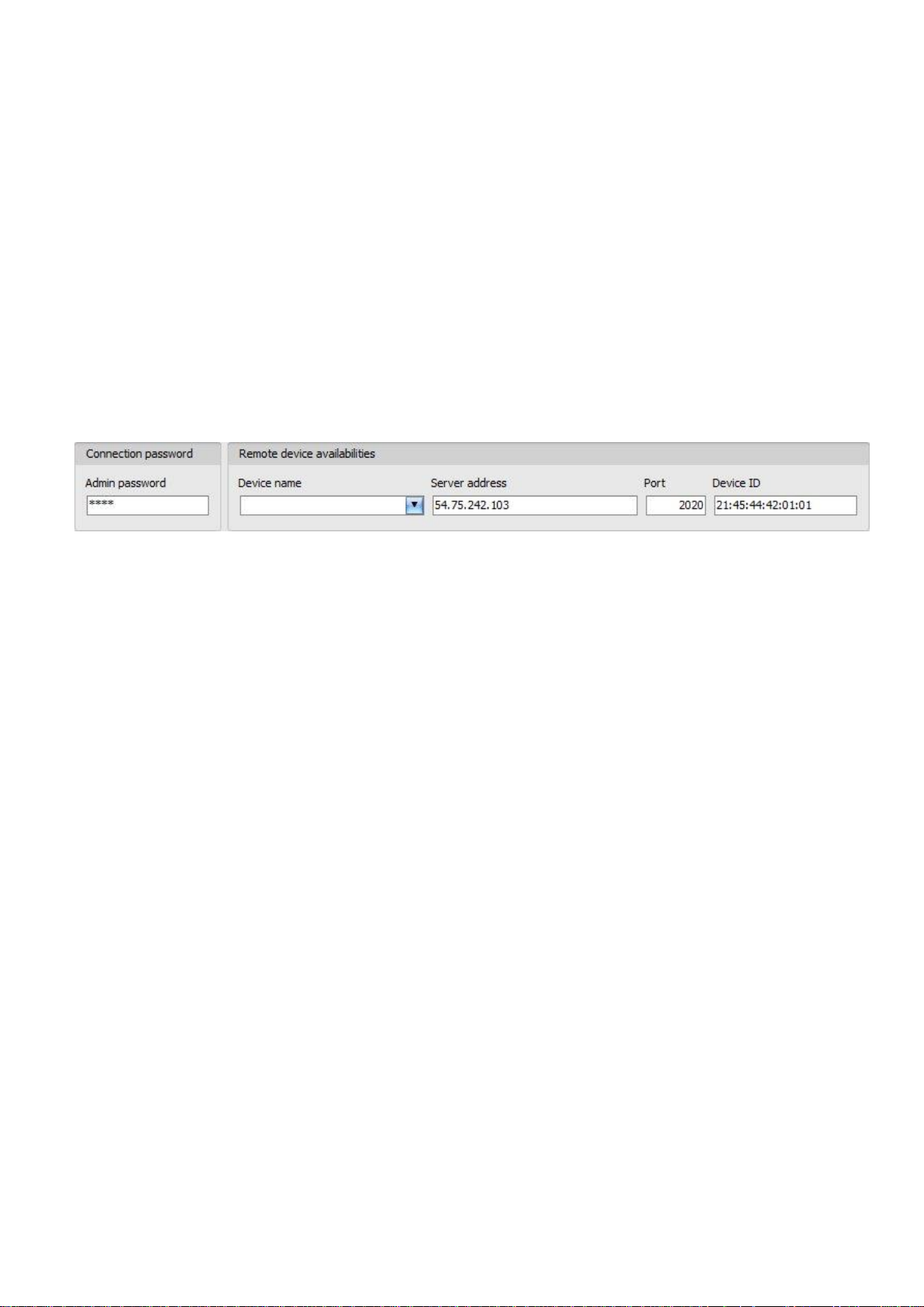
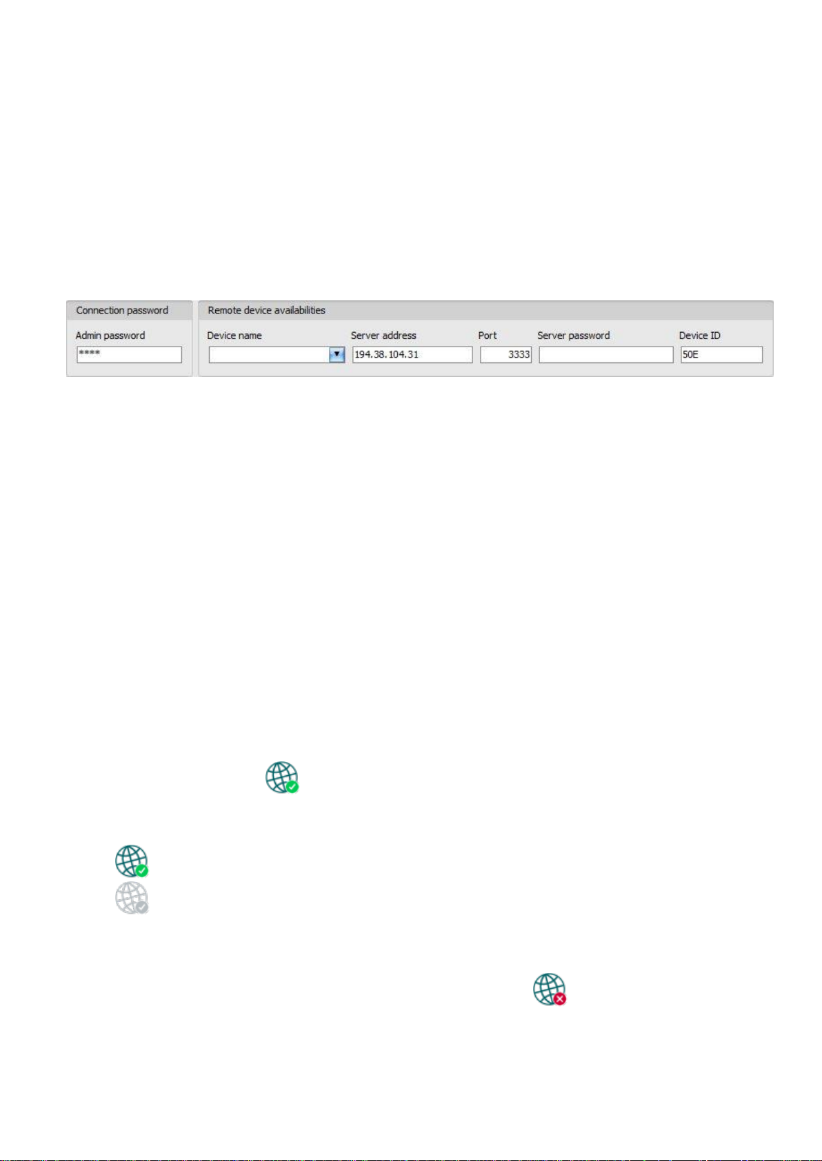
Admin password: the security password of the device (default superadmin password: 1234).
Server address: the IP address of the cloud server (default: 54.75.242.103).
Port: communication port number of the cloud server (default: 2020)
Device ID: the device identifier of the Pager4 device to which you wish to connect.
The format of this unique, burned-in during production and thereby unchangeable device
identifier used for cloud connection is: FF:FF:FF:FF:FF:FF (6x2 hexadecimal characters).
You can read the device ID of the given device in the “Device ID” section of the “Status
monitoring” menu, when connected to the device. The device will also send its device ID as a
reply to your request for connecting to the cloud server, sent by SMS to the device, about which
you can read more below.
Connecting to the device through the cloud server:
Enter the connection password.
o Super administrator permission: full access to all settings. (Default password: 1234).
o Administrator permission: full access to all settings except device identification settings.
o Connecting remotely without a password is not possible.
Select the “Cloud” option in the “Connection type” section.
Fill in the “Server address”, “Port” and “Device ID” fields.
Page 12

12
If cloud usage is enabled in the settings of the given device, the device keeps continuous
connection with the cloud server. In this case skip the SMS sending process mentioned
below. Cloud usage can be enabled in the “General” settings menu. If cloud usage is
disabled, the device will not keep continuous connection with the cloud server, it will only
connect upon request. Therefore, if this is the case, before trying to connect remotely to
the device, the request for connecting to the server should be sent by SMS to the phone
number of the SIM card installed into the device. The device accepts the request for
connecting to the cloud server from the configured and authorized user phone numbers. If
the connecting request is sent from an unauthorized user phone number, or a number
which is not configured in the device, the device password should be added in the
message using the “PWD” parameter, as specified below. In case that the connecting
request command is sent from unauthorized phone numbers without specifying the device
password, or with the wrong password, the device will ignore the request and will not
send any reply to these numbers.
Send the request command for connecting to the server (CONNECT,PWD=device password#)
by SMS to the phone number of the SIM card installed into the device and wait for the device’s
reply. As soon as the device connects to the server, it will send the following reply:
Connected to (IP address:port number)
ID=(device identifier)
Using the “PWD” parameter is optional, according to the following:
PWD: the device password can be specified using this parameter. The superadmin and admin
passwords are both accepted (default superadmin password: 1234). The PWD is an optional
parameter which should be used only when sending commands from phone numbers which are
not configured in the device, or from ones which are configured, but for which other than the
"Accept call and don’t request password" option is assigned in the “Incoming call
management” section – such phone numbers are considered unauthorized, therefore in this
case the password is required).
Example on the usage of the command mentioned above:
When sending from an authorized phone number: CONNECT#
When sending from an unauthorized phone number: CONNECT,PWD=1234#
If cloud usage is disabled in the device settings, the device remains connected to the cloud
server for 10 minutes only and thereafter in case of inactivity it disconnects automatically,
therefore you have 10 minutes to connect to the device after it sends the reply message.
If no reply is received from the device within 1 or 2 minutes, please check if the settings are
correct and if the circumstances of sending the request for connecting satisfy the conditions
mentioned above.
Possible error messages:
Missing APN
the APN is not configured
Network connection error
the device is unable to connect to the Internet due to an
error, faulty settings, or missing Internet service
Page 13
13
If the APN or the cloud server settings are not configured in the device, or are faulty, you can
configure these using the following SMS commands:
SMS command
Specification
APN=APN,PWD=device password#
Configuring the APN
APN=APN,username,password,PWD=device password#
Configuring the APN along
with the username and
password belonging to it
CONNECT=server address:port nr,PWD=device password#
Configuring the cloud server
address and port number, then
connecting to the server
Example on the usage of the commands mentioned above:
APN=internet,PWD=1234#
APN=net,guest,guest,PWD=1234#
CONNECT=54.75.242.103:2020,PWD=1234#
Wait for the device’s reply. After it has confirmed that it has connected to the cloud server,
continue with the next step.
Click on the “Connect” button and wait for the connection to establish. The process
of connecting may take a few seconds.
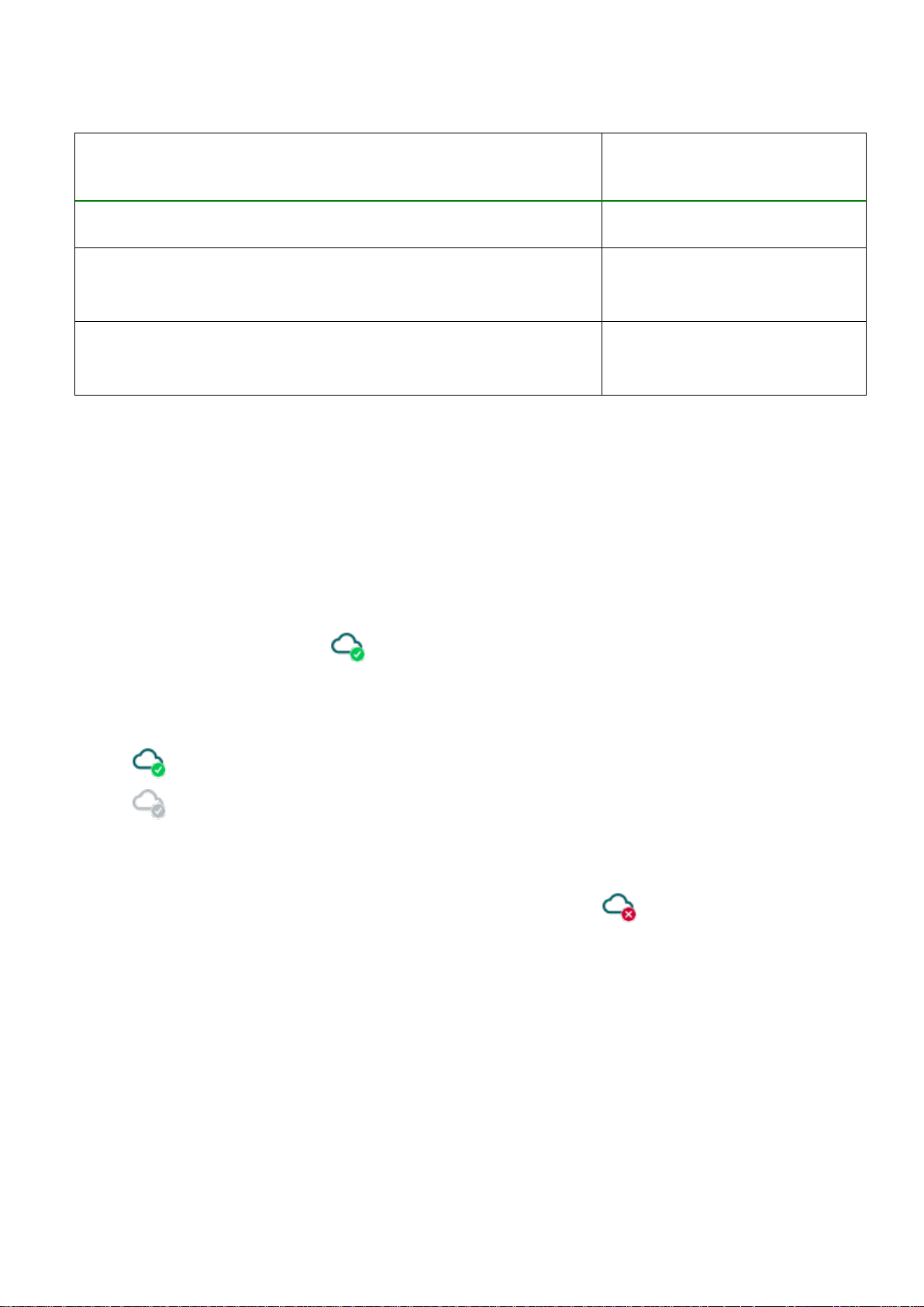
The connection status is indicated by the status icon in the top left corner of the program
window:
disconnected (green)
connected (gray)
After connecting using the valid password, you can configure the device, change settings,
download event logs, monitor system status and perform controls.
To disconnect from the device click on the “Disconnect” button.
Page 14
14
4.2.3 Remote connecting to devices via peer-to-peer connection
This connection type can only be used in a private APN, or through a virtual private
network (VPN) connected to the given private APN. In case of private APN, for the SIM
cards in the given APN, sending and receiving data between each other should be
enabled. The SIM card installed into the Pager4 device you wish to connect remotely to,
should have a static IP address and should be part of the given private APN, respectively
VPN, just like the computer from which you wish to connect to the device. If the computer
is not part of the given private APN through VPN, then you can connect to the device
trough a mobile Internet stick connected to the computer, in which you have to use a SIM
card that is part of the given private APN. Also, the APN settings should be configured in
the device you wish to connect to. These settings are available in the “General” settings
menu.
With this connection type, connection between the device and the Pager4 programming
software will be established directly (peer-to-peer).
The “System logs” option of the programming software cannot be used in case of remote
connection over the Internet.
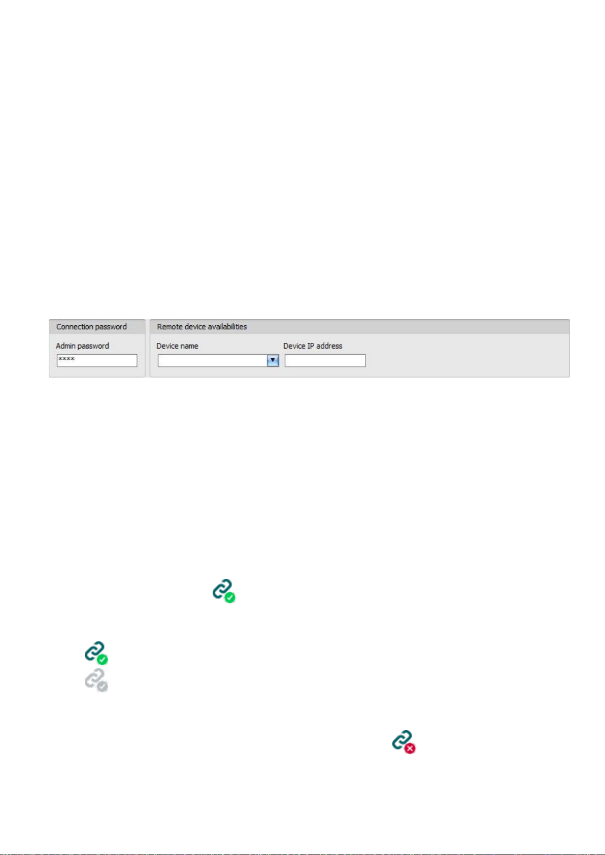
Admin password: the security password of the device (default superadmin password: 1234).
Device IP address: the static IP address of the device you wish to connect to.
Connecting to the device through peer-to-peer connection:
Enter the connection password.
o Super administrator permission: full access to all settings. (Default password: 1234).
o Administrator permission: full access to all settings except device identification settings.
o Connecting remotely without a password is not possible.
Select the “Peer-to-peer” option in the “Connection type” section.
Enter the static IP address of the device you wish to connect to in the “Device IP
address” field.
Click on the “Connect” button.
The connection status is indicated by the status icon in the top left corner of the program
window:
disconnected (green)
connected (gray)
After connecting using the valid password, you can configure the device, change settings,
download event logs, monitor system status and perform controls.
To disconnect from the device click on the “Disconnect” button.
Page 15
15
4.2.4 Remote connecting to devices which are using the TEX-MVP protocol
This connection type can be used if the Pager4 device you wish to connect remotely to, is
connected to a TEX-MVP server. Also use this connection type if the Pager4 device is
connected to a TELLMon receiver and the device is configured to communicate with the
TELLMon receiver using the TEX-MVP protocol.
With this connection type, connection between the device and the Pager4 programming
software can be established through the server/receiver on which the device is online.
The “System logs” option of the programming software cannot be used in case of a remote
connection over the Internet.
Admin password: the security password of the device (default superadmin password: 1234).
Server address: the IP address or domain name of the server on which the device is online.
Port: the communication port number (default TEX communication port: 3333)
Server password: the 20 hexadecimal-character password of the TEX server (5x4 characters
separated by hyphen).
Device ID: the “TEX” identifier of the Pager4 to which you wish to connect to. The format of the
“TEX” device identifier is: FFF (3 hexadecimal characters).
Connecting to the device through a server/receiver which uses the TEX protocol:
Enter the connection password.
o Super administrator permission: full access to all settings. (Default password: 1234).
o Administrator permission: full access to all settings except device identification settings.
o Connecting remotely without a password is not possible.
Select the “TEX-MVP” option in the “Connection type” section.
Fill in the “Server address”, “Port”, “Server password” and “Device ID” fields.
Click the “Connect” button.
The connection status is indicated by the status icon in the top left corner of the program
window:
disconnected (green)
connected (grey)
After connecting using the valid password, you can configure the device, change settings,
download event logs, monitor system status and perform controls.
To disconnect from the device click on the “Disconnect” button.
Page 16
16
4.2.5 Remote connecting to devices which are using the TELLMon protocol
This connection type can be used if the Pager4 device you wish to connect remotely to, is
connected to a TELLMon receiver and the device is configured to communicate with the
TELLMon receiver using the TELLMon protocol.
With this connection type, connection between the device and the Pager4 programming
software can be established through the receiver on which the device is online.
The “System logs” option of the programming software cannot be used in case of remote
connection over the Internet.
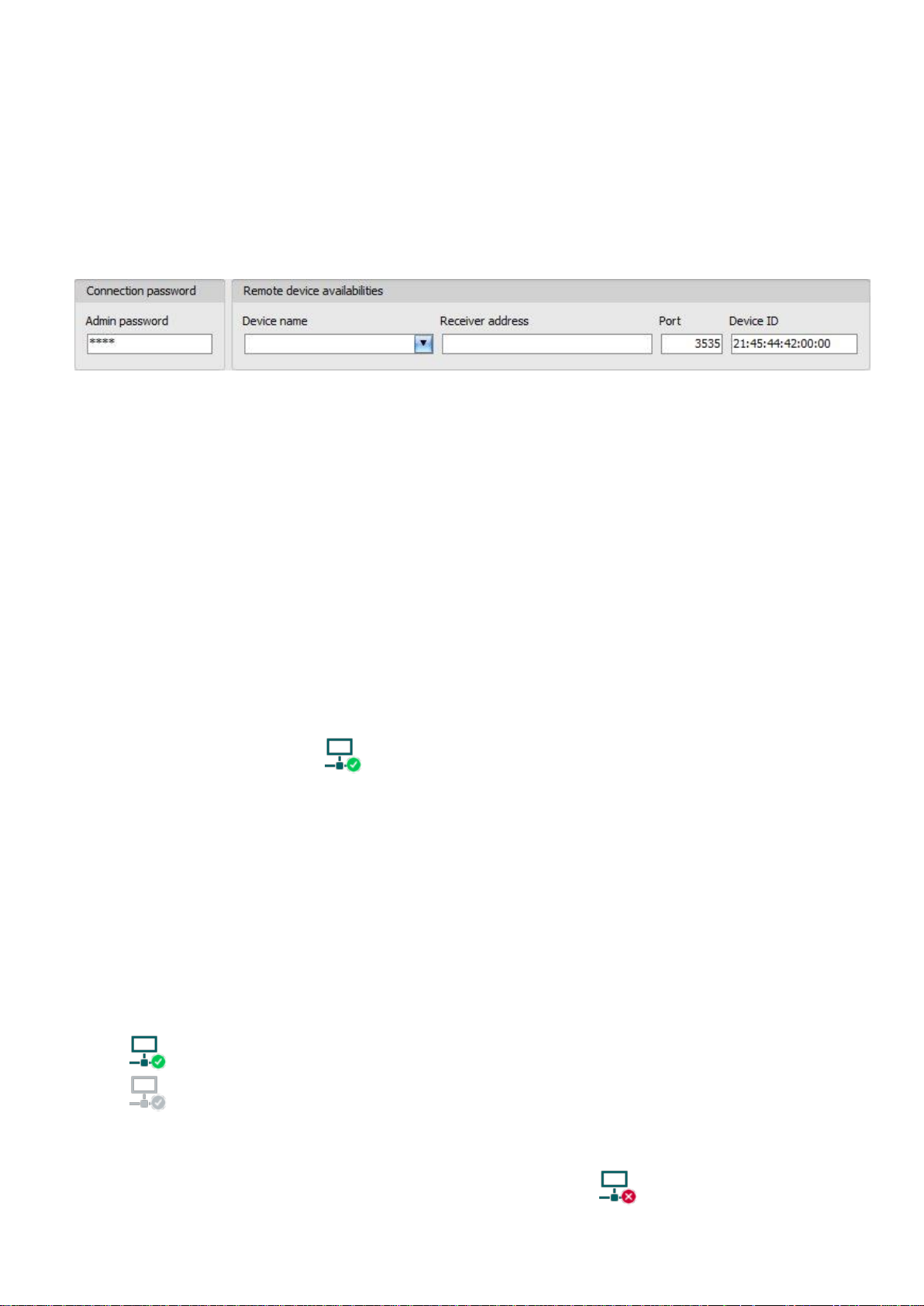
Admin password: the security password of the device (default superadmin password: 1234).
Receiver address: the IP address or domain name of the receiver on which the device is online.
Port: communication port number (the default TELLMon communication port is: 3535)
Device ID: the device identifier of the Pager4 device to which you wish to connect to.
The format of this unique, burned-in during production and thereby unchangeable device
identifier used for the TELLMon protocol is: FF:FF:FF:FF:FF:FF (6x2 hexadecimal characters).
Connecting to the device through a server/receiver which uses the TELLMon protocol:
Enter the connection password.
o Super administrator permission: full access to all settings. (Default password: 1234).
o Administrator permission: full access to all settings except device identification settings.
o Connecting remotely without a password is not possible.
Select the “TELLMon” option in the “Connection type” section.
Fill in the “Receiver address”, “Port” and “Device ID” fields.
Click on the “Connect” button.
The Adapter2 device that communicates using the TELLMon protocol is not online
continuously. The device connects to the receiver only when it sends a supervision
or event message, therefore after clicking the “Connect” button, you have to wait
until the device next connects to the receiver for sending a supervision or event
message. This is when the programming software will have possibility to connect
to the device. Therefore, if the device is configured to rarely send supervision
messages towards the TELLMon receiver, in this case the programming software
will be able to connect to the device after a long time only (depending on the
interval of supervision message sending).
The connection status is indicated by the status icon in the top left corner of the program
window:
disconnected (green)
connected (gray)
After connecting using the valid password, you can configure the device, change settings,
download event logs, monitor system status and perform controls.
To disconnect from the device click on the “Disconnect” button.
Page 17
17
5 How to use the Pager4 programming software
5.1 Connection menu
5.1.1 Viewing the settings options and configuring offline
The Pager4 programming software supports all Pager4 device models, therefore the software
shows the settings and control options available specifically in a given device model, which are
different from the common parameters (e.g. differences between the PRO and non PRO, or
device models with a different number of inputs) only when connecting the given device model,
i.e. a Pager4 device has to be connected in order to show the specific settings options of that
device model.
However, using the “Offline device selector” it is possible to view the settings options of any
Pager4 device model and to configure and save the settings in advance offline, without
connecting the device.
If you wish to view the settings options of a Pager4 device model, or to configure and
save settings without connecting the device, click on the arrow found next to the
“Offline device selector” button, select the desired device model from the drop-down
menu and then click on the “Offline device selector” button to load the settings options of
the selected device model.
Page 18
18
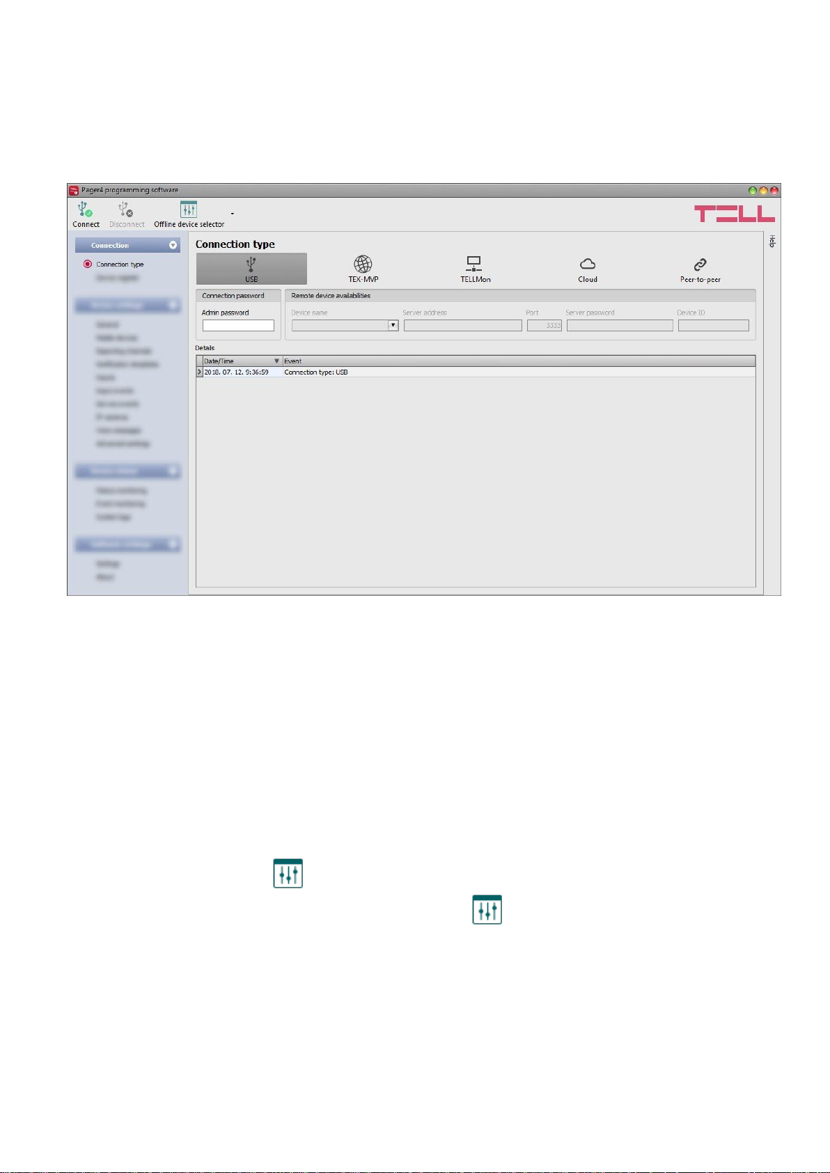
5.1.2 Connection type
In the “Connection type” menu the type of connection can be selected (USB or different options
for connecting over the Internet), information can be seen about the connection process, and the
admin and superadmin password can be changed. The default superadmin password is 1234.
If you wish to use the admin level access as well, for this the password should be configured
separately by clicking on the “Change Admin password” button (for “Actual password” enter
the superadmin password).
Available options:
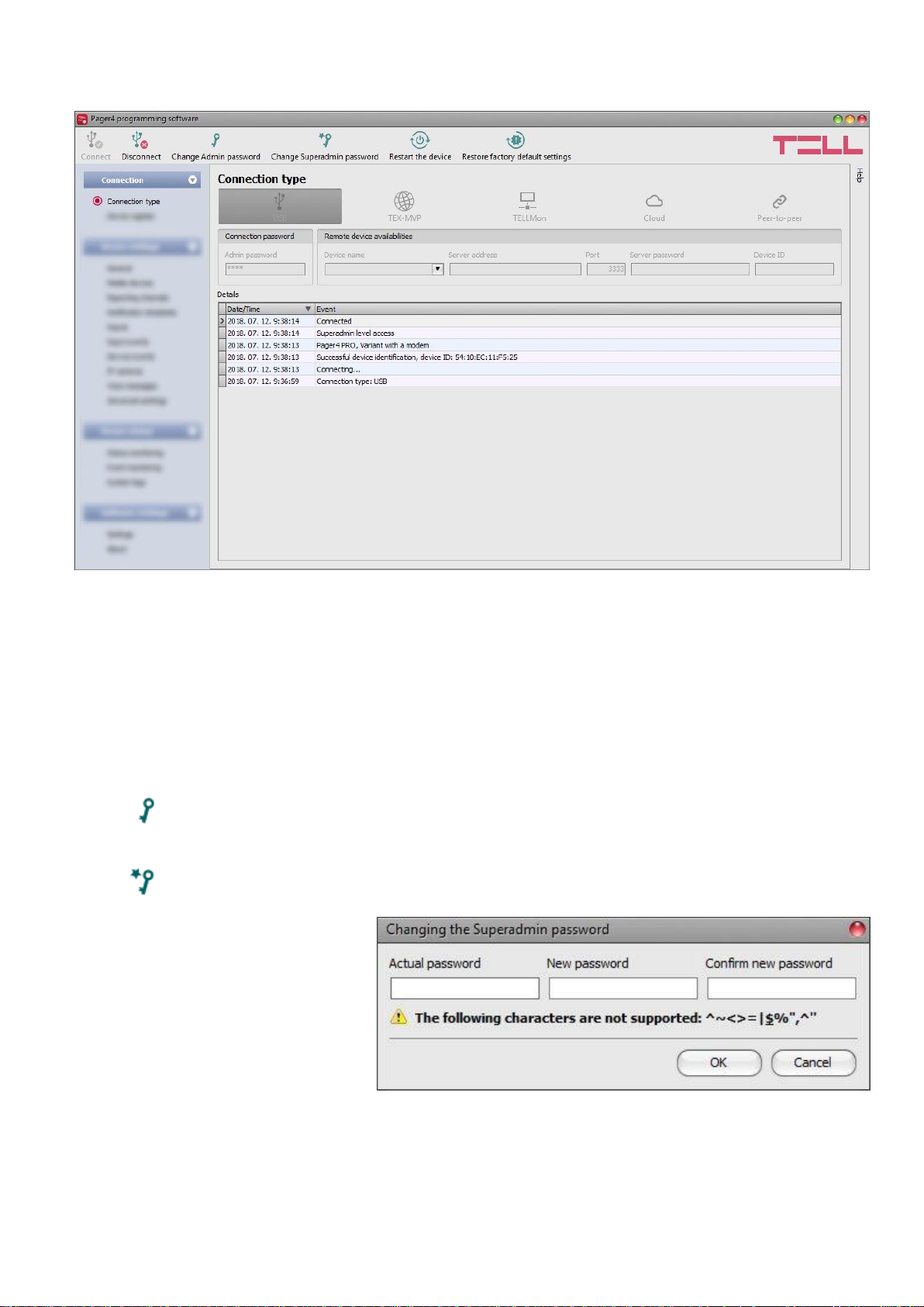
Change Admin password:
The administrator level password can be changed after clicking on this button.
Change Superadmin password:
The superadministrator level password can be changed after clicking on this button.
Enter the actual password, then
the new password and its
confirmation, then click “OK”. The
password should consist of at
least 4, but not more than
8 characters. Accepted characters
are: numbers (0...9), lower case
letters (a...z), and capital letters
(A...Z).
Attention! The following characters should not be used: ^ ~ < > = | $ % " '.
Details: in this window you can follow the connection progress.
Page 19
19
Restart the device:
If needed, you can restart the connected device by clicking on this button.
Restore factory default settings:
By clicking on this button, you can restore the factory default settings in the device.
Restoring the factory default settings will erase the actual settings, therefore please
save your settings if needed. The reset process may take more than 1 minute and
involves a device restart. Wait until the device restarts and the LED indicator starts
working again. The option of restoring the factory default settings is also available without
entering the device password. Factory reset can also be performed using the microswitch
found on the hardware. Further details you can find in chapter “Factory reset”.
The factory default settings cannot be restored if the device has been locked in the
settings. If you have forgotten the device passwords and the device is locked, only the
manufacturer can restore the factory default settings in the service center.
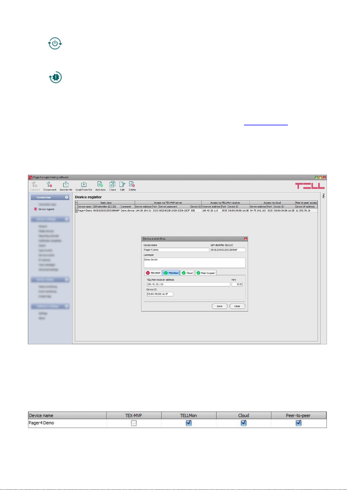
5.1.3 Device register
The device register serves for storing and easy handling of device availabilities used for remote
programming. You can add new device availabilities to the database and also edit, delete and
clone entries for easy adding of devices with similar availabilities.
When connecting remotely, you can easily select by name the device you wish to connect to
from the “Device name” drop-down menu, out of the devices added to the database. In the
drop-down menu the program indicates which types of connection have been configured for the
given device, which helps you select the appropriate connection type.
If you add a new device availability in the connection type section, the program will add it
automatically to the device register database by using the device ID as device name, which you
can then change by editing the given entry. The database is stored locally on the computer.
Page 20

20
Function buttons available in the “Device register” menu:
: save database to file
: load database from file
: add new device
: clone entry (duplicate)
: edit entry
: delete entry
Data stored by the device register:
Device name: custom name
SIM identifier (ICCID): the identifier of the SIM card inserted into the device (if the SIM card is
inserted, the software reads the ID automatically from the device and inserts the data in this field
when you create a new device availability entry)
Comment: in this field you can enter custom comments related to the given device
Connection type: you can configure multiple remote availabilities for the same device
(TEX-MVP, TELLMon, cloud, peer-to-peer), according to what type of server or receiver the
device connects to. The availabilities belonging to given types of connection can be configured
under the tabs labeled with the name of the connection type.
A green icon will be shown on the tabs of connection types for which device availabilities
have already been provided, and a red icon will be shown on the tabs where availabilities
have not been configured or the data are deficient. To make it easier for you, the program will
automatically fill in the data fields for connection types for which the availabilities are available
(e.g. if the device is connected via USB, the program knows the availability of the cloud server,
and the necessary device identifier will be read automatically from the device via USB).
Server/receiver address: the IP address or domain name of the server/receiver
Device IP address: the static IP address of the device (in case of private APN)
Port: the communication port number of the server/receiver
Server password: (for TEX-MVP protocol only) the 20 hexadecimal-character server password
(5x4 characters separated by hyphen)
Device ID: the device identifier. The format of the device identifier is:
- for cloud usage and the TELLMon protocol: FF:FF:FF:FF:FF:FF (6x2 hexadecimal
characters, unique, burned-in during production and thereby unchangeable device
identifier). The device ID (used for cloud connection and the TELLMon protocol) of the
connected device is shown in the “Status monitoring” menu / “Device ID” field.
- for the TEX-MVP protocol: FFF (3 hexadecimal characters)
Page 21

21
5.2 Device settings menu
You can configure the device settings in the submenus available in the “Devise settings” menu.
Changing the device settings: In order to change the device settings, first you have to
read the actual settings from the device by clicking on the “Read” button in any
submenu. Writing the settings into the device using the “Write” button is not possible
until the settings are read.
Overwriting the device settings: If you want to completely overwrite the settings, you can
import and write from a saved file. To create a settings file, configure the desired settings in
the submenus, and then click on the “Save to file” button. You can import the saved
settings file into the program using the “Load from file” button, and then write into the
device by clicking on the “Write” button. This is useful when you want to configure
many devices with the same settings.
5.2.1 General
In this section you can configure the parameters related to general operation of the device.
Page 22

22
Available options:
Read the settings from the device:
To read the settings from the device click on the “Read” button. This will read all
settings in all menus.
Write the settings into the device:
After changing the settings or entering new settings, in order to take effect, it is
necessary to write the new settings into the device by clicking on the “Write”
button. This will write the changes only, but all changes made in any menu.
Save settings to file:
To save all device settings to file click on the “Save to file” button.
Load settings from file:
To load saved settings from file click on the “Load from file” button.
Firmware update:
By clicking on the “Firmware update” button, the firmware of the device can be
updated. Clicking on the button, opens a pop-up window, where you can browse
the firmware file with tf3 extension. When firmware upload is finished, the progress
window closes automatically and 5 seconds later the device restarts with the new
firmware.
Please note that the settings have to be written in the device in order to be applied after a
change is made. For this, click on the “Write” button.
SIM:
PIN code: if you wish to use PIN code management, enter in this section the PIN code of the
SIM card installed into the device. Otherwise disable PIN code request on the SIM card. If the
wrong PIN code has been entered, the device will try the code only once each time the code is
changed in the settings and PIN code error message will be shown in the system logs. If the
wrong code is configured 3 times consecutively, the SIM card will reach the PUK code request
stage. In this case install the SIM card into a cellphone, unlock the card by entering the PUK
code when requested, and configure the valid PIN code in the device settings.
APN: the APN name necessary to connect to the Internet. (ask this from the GSM service
provider of the SIM card installed into the device). If no APN is configured, the device will not try
to connect to the Internet. In this case you can only use the functions which do not require
Internet connection, such as voice calls and SMS sending.
APN user name: necessary only if the GSM service provider provides this and requires its
usage for the given APN.
APN password: necessary only if the GSM service provider provides this and requires its usage
for the given APN.
Page 23

23
Arming / Disarming:
Arming / Disarming options: the device can also be used as a standalone alarm control device
and can be armed/disarmed using dry contacts on inputs or remotely by phone call or SMS, or
by using the arming/disarming controls in the programming software. For arming/disarming by
dry contacts you can use any accessory which has dry contact outputs, e.g. access control
keypad, card reader, RF remote controller, key switch or a simple switch, pushbutton, etc.
In order to make it possible to use the device according to the demands, different
arming/disarming options are available:
Always armed: choose this control mode if you do not wish to arm and disarm the device,
but the inputs should always be armed, events should be generated and notifications
should be sent when activated. In this case arming and disarming will not be available and
all inputs will act as 24h zones.
Bistable contact: choose this control mode if you wish to arm and disarm the device using
a toggle switch or relay output (open or closed). This control mode uses input IN4 (for the
IN4.R2 model) or input IN6 (for the IN6.R1 model), which in this case can be used for
arming/disarming only. When input IN4/IN6 is active, the device will be armed, and when
inactive, the device will be disarmed. Assigning the open/closed state of the dry contact to
the active/inactive state of the input can be done by configuring the input type (normally
open or normally closed) for the given input (IN4/IN6).
For normally open (NO): open=inactive=device disarmed, closed=active=device armed.
For normally closed (NC): open=active=device armed, closed=inactive=device disarmed.
Since the state of the dry contact defines the armed/disarmed status, therefore remote
arming and disarming is not available for this control mode.
Impulse on one input: choose this control mode if you wish to arm and disarm the device
by dry contact impulses (e.g. pushbutton, or monostable relay output) using up one input.
This control mode uses input IN4 (for the IN4.R2 model) or input IN6 (for the IN6.R1
model), which in this case can be used for arming/disarming only. The device will become
armed when input IN4/IN6 is activated shortly (impulse), then it will become disarmed upon
next short activation of the same input. Assigning the open/closed state of the dry contact
to the active/inactive state of the input can be done by configuring the input type (normally
open or normally closed) for the given input (IN4/IN6).
For normally open (NO): open=inactive, closed=active.
For normally closed (NC): open=active, closed=inactive.
Remote arming and disarming is also available for this control mode.
Impulse on two inputs: choose this control mode if you wish to arm and disarm the device
by dry contact impulses (e.g. pushbuttons, or monostable relay outputs) using up two
inputs. This control mode uses inputs IN3 and IN4 (for the IN4.R2 model) or inputs IN5 and
IN6 (for the IN6.R1 model), which in this case can be used for arming/disarming only. The
device will become armed when input IN3/IN5 is activated shortly (impulse), then it will
become disarmed when input IN4/IN6 is activated shortly. Assigning the open/closed state
of the dry contact to the active/inactive state of the inputs can be done by configuring the
input type (normally open or normally closed) for the given inputs (IN3/IN5 and IN4/IN6).
For normally open (NO): open=inactive, closed=active.
For normally closed (NC): open=active, closed=inactive.
Remote arming and disarming is also available for this control mode.
Remote arming/disarming only: choose this control mode if you wish to use all inputs for
custom notifications, In this case the device cannot be armed and disarmed locally through
the inputs. Arming and disarming can only be done remotely by phone call, SMS, or by
using the arming/disarming controls in the programming software.
Page 24

24
Limitation of alarms (auto zone shutdown):
Maximum number of alarms per zone (1 to 100pcs): in this section you can configure the
maximum number of alarms (activation events) to be accepted from one input. This makes it
possible to avoid a faulty detector connected to an input to generate alarms and notifications
continuously. If the number of alarm events generated by an input reaches the value configured
here, the given input will become restricted and the device will ignore further activation events of
the given input.
If the arming/disarming settings are not configured to “Always armed”, disarming and rearming
the device will re-enable the restricted input, then alarm events will be accepted again from the
given input, but again only the number of alarm events configured. If the arming/disarming
settings are configured to “Always armed”, or the “24h zone” option is enabled for the given
input, the restricted input will be re-enabled automatically when the time configured at the
“Duration of limitation” option expires. The restriction only applies to inputs for which the
“Auto shutdown” option is enabled.
Duration of limitation (1 to 24h): in this section you can configure how long the device should
ignore an input which has reached the limitation value entered at "Maximum number of alarms
per zone" option. When this period of time expires, the alarm counter will be reset automatically
and the input will be enabled again. This setting only applies to inputs for which both the
“Auto shutdown” and “24h zone” option is enabled, or to any input for which the
“Auto shutdown” option is enabled, if the arming/disarming settings are configured to
„Always armed”.
Periodic test report:
Interval of sending (1 to 168h): the interval of periodic test report sending.
Time of day (hh:mm): the time of day for periodic test report sending.
Cloud server:
Cloud usage: if this option is enabled, the device will connect to the cloud server operated by
the manufacturer and will stay connected continuously. Using the cloud server, special services
become available, such as remote programming, control and monitoring of your device.
If enabled, the device will always be online and thereby accessible at anytime. If disabled, the
device will connect to the cloud server only upon request sent by SMS to the phone number of
the device. You can read more about this in the “Remote connecting to devices via cloud
service” paragraph.
Server address: the IP address of the cloud server (default: 54.75.242.103)
Server port: the port number of the cloud server (default: 2020)
Identification:
User account ID: the user account ID necessary for Contact ID reporting to CMS. The events
and, if using the TELLMon or TEX protocol, the supervision messages are also sent using the
user account ID configured in this section. The user account ID length is 4 hexadecimal
characters and the following characters can be used: 0..9, A, B, C, D, E, F.
Group ID: the CMS identifier in hexadecimal format. This is only required if the TEX protocol is
used for reporting to CMS. If you do not possess this identifier, please contact your reseller.
Device ID: the device identifier in hexadecimal format. This is only required if the TEX protocol is
used for reporting to CMS. The length is 3 characters and the following characters can be used:
0…9, A, B, C, D, E, F.
Page 25

25
SIA user account ID: in case of using the SIA IP protocol, the supervision messages are sent to
CMS using the user account ID configured in this section. The length of the SIA user account ID
is 1 to 6 hexadecimal characters, and the following characters can be used: 0..9, A, B, C, D, E,
F. Do not fill in the account ID section with zeros!
Note! The user account ID, group ID, device ID and SIA user account ID are only needed if
reporting to CMS is used.
Low supply voltage event:
Low voltage threshold: the device has built-in supply voltage monitoring function. In this
section you can configure the threshold from 10 to 30V, at which the device will generate
the “Low supply voltage” event. The event will be generated if the supply voltage is
continuously at, or below the configured level for at least 30 seconds.
Low voltage restore threshold: In this section you can configure the threshold from 10 to
30V, at which the device will generate the “Low supply voltage” restore event. The event
will be generated if the supply voltage is continuously at, or above the set level for at
least 30 seconds after a “Low supply voltage” event.
System time:
NTP server 1,2: in this section you can select one of the default NTP servers or you can also
configure custom NTP servers which you wish to use for system time synchronization.
The device synchronizes the system time from the GSM network and if this fails, it will use the
NTP servers. If synchronization from the NTP servers also fails, it will synchronize the date and
time using the timestamp received from a CMS server/receiver, if CMS is used.
Time zone: select the time zone according to the location of installation. The device adjusts the
system time according to the time zone setting. If the setting is wrong, there will be difference
between the system time and the local time and therefore the timestamps of the events will also
be wrong and the periodic test report will also be sent at the wrong time of day.
Miscellaneous settings:
Incoming call from unknown phone number: in this section you can configure what the
device should do upon a phone call received from a phone number which is not configured in the
device as a user phone number, or a call received with hidden caller ID. You can configure the
device to accept or reject these calls. Independently of the selected option, receiving a call from
an unknown phone number also generates a service event, which you can configure separately
to control the output(s) or send notifications.
SMS forwarding phone number: the device forwards the messages received by its SIM card to
the phone number configured in this section (e.g. balance information received from the GSM
service provider in case of pre-pay card). The received messages are deleted automatically after
forwarding. If no phone number is configured, the device deletes all incoming messages without
forwarding.
Page 26

26
5.2.2 Mobile devices (Pager4 PRO only)
In this menu you can manage the access of mobile applications. The device supports access of
up to 4 mobile devices, for which you can configure here the registration password requested
upon assigning the mobile application to the device, and it is also possible to delete a mobile
device if needed, i.e. to cancel its assignment/registration. The mobile application can be
assigned to the device with the help of a QR code, which you can generate by clicking on the
“QR code” button.
Available options:
Read the settings from the device:
To read the settings from the device click on the “Read” button. This will read all
settings in all menus.
Write the settings into the device:
After changing the settings or entering new settings, in order to take effect, it is
necessary to write the new settings into the device by clicking on the “Write”
button. This will write the changes only, but all changes made in any menu.
Save settings to file:
To save all device settings to file click on the “Save to file” button.
Load settings from file:
To load saved settings from file click on the “Load from file” button.
Page 27

27
QR code:
The “QR code” button can be used to generate the QR code necessary for
assigning the mobile application to the device. The QR code includes connection
data: device ID, server IP address and port number, and the sequence number of
the mobile device / user (1 to 4).
A different QR code belongs to each mobile device (1 to 4). You can select the desired
mobile device using the “Mobile device” drop-down menu. The QR code selected this
way can be copied to clipboard, saved to file or printed by clicking on the appropriate
buttons.
Please note that the settings have to be written in the device in order to be applied after a
change is made. For this, click on the “Write” button.
Device manager:
In case of assigning a mobile application to the Pager4 device, receiving alerts from the device
will become available through Push notification too. For this, when configuring events, you can
select which of the maximum 4 (PUSH1…PUSH4) assigned mobile devices you wish to receive
a Push notification on when the given event occurs.
Name: the name of mobile device’s user. The name entered in this section will be used to
identify the mobile devices upon selecting the notification channels when configuring events.
Registration password: the registration password has to be provided in the mobile application
when you wish to assign it to the device. This password can be configured in this section
separately for each mobile device to be assigned. The registration password length is 4 to 8
characters and only letters and numbers are accepted. Accented letters are not accepted.
Mobile device: this field shows the name of the given device already assigned, which is read by
the mobile application from the mobile device, therefore this name cannot be changed in the
programming software.
APP ID: this field shows the identifier of the given assigned mobile device. This identifier is used
to identify the mobile device and it is unique for each device.
Delete: the “Delete” button is used to delete the given mobile device, i.e. to cancel its
assignment/registration. In case of deleting a mobile device, the application used on the given
device will no longer have access to the Pager4 device.
Page 28

28
5.2.3 Reporting channels
In this section you can configure all availabilities where reports and notifications should be sent,
such as CMS servers and receivers, user phone numbers for calls and SMS sending, and e-mail
addresses for notification by e-mail in case of using the Pager4 PRO model.
Available options:
Read the settings from the device:
To read the settings from the device click on the “Read” button. This will read all
settings in all menus.
Write the settings into the device:
After changing the settings or entering new settings, in order to take effect, it is
necessary to write the new settings into the device by clicking on the “Write”
button. This will write the changes only, but all changes made in any menu.
Save settings to file:
To save all device settings to file click on the “Save to file” button.
Load settings from file:
To load saved settings from file click on the “Load from file” button.
Please note that the settings have to be written in the device in order to be applied after a
change is made. For this, click on the “Write” button.
Page 29

29
CID reporting to CMS over IP:
You can configure up to 4 IP availabilities of CMS servers or receivers as follows.
Name: CMS server or receiver name. The name entered in this section is used for identification
of the server/receiver within the program, and the program will also use this name when
configuring notification templates.
IP address/domain name: CMS server or receiver IP address or domain name. When a SIM
card with a private APN is used, and the given server or receiver is not in the same APN, it is
necessary to enable access of the server/receiver IP address in the given APN.
Port: CMS server or receiver communication port number.
Protocol: select the appropriate communication protocol for the given server or receiver from
the drop-down menu. Available protocols: TELLMon, TEX, SIA IP (ANSI/SIA DC-09-2007).
Supervision message: enable/disable supervision message sending. Supervision message
sending cannot be disabled in case of using the TEX or the TELLMon communication protocol.
Supervision message interval / Unit of measure: if supervision message sending is enabled,
you can configure the sending interval and unit of measure. The supervision message sending
interval can be configured from 10 seconds to 30 minutes.
Network protocol: according to the chosen communication protocol you can use TCP or UDP
network protocol. The UDP protocol allows for less data traffic. For TEX communication protocol
only TCP network protocol is available.
AES key: the custom AES encryption key can be used for SIA IP protocol only. If an encryption
key is configured, the SIA IP packages will be encrypted with the given key and they have to be
decrypted on the receiver side using the same key. The maximum length of the AES key is up to
16 characters, or up to 32 characters in case of using hexadecimal format.
Send each message in a new session: if required for the given receiver, in case of the
SIA DC-09 protocol it can be enabled to send each message in a new TCP session. In case of
using UDP, if this option is enabled, the device will open a new port for each message.
CID reporting to CMS over DTMF-based voice call:
Please note that in certain cases you may experience issues with reporting to CMS over DTMFbased voice call. Success of communication highly depends on the properties of the given GSM
network, such as line quality, line noise and DTMF handling. Due to network digitalization, DTMF
signal tones might get distorted while being processed by the network in such extent that the
receiver will not be able to interpret the transmitted Contact ID event codes. The risk of this is
even higher if the signal is transmitted through multiple GSM operators (e.g. if using SIM cards
from different operators on the transmission and reception site). The device offers an option to
adjust the signals in order to correct such problems, therefore if necessary, special DTMF
communication parameters can be configured in the “Advanced settings” menu.
You can configure up to 2 DTMF receiver phone numbers (TEL1 DTMF and TEL2 DTMF) as
follows.
Name: CMS DTMF receiver name. The name entered in this section is used for identification of
the receiver within the program, and the program will also use this name when configuring
notification templates.
Phone number: the phone number of the DTMF receiver.
Page 30

30
User phone number settings:
You can configure up to 10 user phone numbers (TEL1 to TEL10) for voice calls, SMS sending
and remote control by SMS and calls.
Name: user name. The name entered in this section will be used upon selecting the notification
channels when configuring events.
Phone number: user phone number.
Event acknowledgement options: when the device sends a notification by call, it requires a
confirmation that the notification has been received, otherwise it will retry to deliver the
notification. In this section you can configure the actions required from each user upon receiving
a notification by voice call. Available options:
Accept call to acknowledge: notifications will be acknowledged automatically upon
accepting the calls. After accepting the call, wait at least 3 seconds before ending the call.
Reject or accept call to acknowledge: notifications will be acknowledged automatically if
the calls are rejected by user, and also if the calls are accepted.
Press to acknowledge: notifications have to be acknowledged by pressing the star ()
key on the phone after accepting the call. The device will confirm that it has received the
command by a short signal tone.
Press to acknowledge or # to stop notification: notifications have to be
acknowledged by pressing the star () key on the phone after accepting the call.
The device will confirm that it has received the command by a short signal tone.
Notification of further users on the given event can be stopped by pressing the hash (#) key
on the phone. The device will confirm that it has received this command by three short
signal tones. By pressing the hash (#) key, this also confirms reception of the notification at
the same time, so it is not necessary to press the star () key too.
By this option it is also possible to cancel all pending notifications for all events by entering
the device password# command (e.g. 1234#) using the phone’s keys. The
superadmin and admin passwords are both accepted.
Incoming call management: in this section you can configure for each user what should the
device do when it receives a call from the given user. Independently of the selected option,
receiving a call from a user phone number also generates a service event, which you can
configure separately to control the output(s) or send notifications. Available options:
Accept call and request password: the device accepts the call which it confirms by a
short signal tone and then the password should be entered in order to accept commands.
The superadmin and admin passwords are both accepted. The user needs to enter the
valid password using the phone’s keys as follows: 9device password# (e.g. 91234#).
If the valid password has been entered, the device confirms this by three short signal
tones, otherwise a long signal tone will be emitted. If the command is wrong (missing or
#), no signal tone will be emitted. After the password has been accepted, the caller can use
commands as specified in the list of DTMF commands. The device will also identify the
user’s phone number by CLIP service, which makes it possible to perform further actions
automatically upon receiving the call. For this, an “incoming call from user” event should
be configured for the given phone number at the service events.
Accept call and don’t request password: the device accepts the call which it confirms by
a short signal tone and then commands can be used as specified in the list of DTMF
commands, without the need of entering the password. The device will also identify the
user’s phone number by CLIP service, which makes it possible to perform further actions
automatically upon receiving the call. For this, an “incoming call from user” event should
be configured for the given phone number at the service events.
Page 31

31
Reject call: the device will reject calls received from the given user phone number, but will
identify the phone number by CLIP service for further actions, which are available by
configuring an “incoming call from user” event for the given phone number at the service
events. By rejecting the calls, the configured actions can be performed free of charge
(except if the given GSM service provider applies a charge for rejected calls as well).
E-mail notification recipients (Pager4 PRO only):
You can configure up to 4 e-mail addresses (MAIL1 to MAIL4) to which the device will send
notification upon event occurrence, according to the event settings.
Name: user/recipient name. The name entered in this section will be used upon selecting the
notification channels when configuring events.
E-mail address: user/recipient e-mail address. You can configure 1 e-mail address per user.
5.2.4 Notification templates
Notification templates should only be configured if reporting to CMS is needed. In this menu you
can configure different templates according to which the device will send reports to CMS servers
and receivers. For quick and easy setup, the device contains 2 built-in templates, named as
“EMPTY” and “DEFAULT”, which cannot be deleted, but their configuration can be changed if
needed. If you wish to add new notification templates, this should be done prior to configuring
events. Any template can be assigned to any event, thus reports can be directed to the desired
servers and receivers using the desired priorities. Servers/receivers are classified into two
groups, primary and backup. When an event occurs, the given report will be sent to all servers
and receivers configured as primary in the notification template assigned to the given event.
In case that none of the primary servers/receivers are available, the device will try to report to
the servers/receivers configured as backup.
The order of reporting to servers and receivers configured as backup in a template corresponds
to the numbering (1 to 6) of the channels in the template. The priority depends on the
classification of the configured servers/receivers (primary or backup). Primary servers/receivers
will be notified first.
Page 32

32
Reports will be sent to all primary servers/receivers, while backup servers/receivers will only be
notified if reporting to all primary ones fail. In this case the device tries to report to the first
highest priority backup server/receiver, then if this fails, to the second and so on.
Additionally, if a reporting channel fails, the devices will keep sending supervision signals to the
given server/receiver by the configured supervision sending interval to check its availability and
will send the report as soon as it becomes available. The device will no longer try to report
events for which reporting failed for more than 1 hour.
Notification templates cannot be deleted while they are assigned to an event. The system allows
for adding at most 10 notification templates, including the built-in ones.
Available options:
Read the settings from the device:
To read the settings from the device click on the “Read” button. This will read all
settings in all menus.
Write the settings into the device:
After changing the settings or entering new settings, in order to take effect, it is
necessary to write the new settings into the device by clicking on the “Write”
button. This will write the changes only, but all changes made in any menu.
Save settings to file:
To save all device settings to file click on the “Save to file” button.
Load settings from file:
To load saved settings from file click on the “Load from file” button.
Add new notification template:
To add a new notification template click on the “New” button.
Create a copy of an existing template:
To create a copy of the selected template click on the “Clone” button. Please note
that the new copy should have a different unique name.
Edit an existing template:
To edit the selected template click on the “Edit” button.
Delete a template:
To delete the selected template click on the “Delete” button.
Please note that the settings have to be written in the device in order to be applied after a
change is made. For this, click on the “Write” button.
Creating a new notification template:
Click on the “New” button.
Enter a name for the new template. The name should not be longer than 20 characters,
and the following characters should not be used: ^ ~ < > = | $ % " '.
Configure the channels and the reporting priority.
Click on the “OK” button.
Click on the “Write” button.
Page 33

33
5.2.5 Inputs
In this menu you can configure the properties and options of the dry contact inputs.
Available options:
Read the settings from the device:
To read the settings from the device click on the “Read” button. This will read all
settings in all menus.
Write the settings into the device:
After changing the settings or entering new settings, in order to take effect, it is
necessary to write the new settings into the device by clicking on the “Write”
button. This will write the changes only, but all changes made in any menu.
Save settings to file:
To save all device settings to file click on the “Save to file” button.
Load settings from file:
To load saved settings from file click on the “Load from file” button.
Edit input settings:
To edit the settings of the selected input click on the “Edit” button.
Please note that the settings have to be written in the device in order to be applied after a
change is made. For this, click on the “Write” button.
Page 34

34
Input properties:
Identifier: the identifiers of the inputs cannot be changed. They are used for identification of the
inputs in the program.
Input type: the input can be normally open (NO), or normally closed (NC). When set to NO,
event is generated when the input circuit is closed, while when set to NC, opening the input
circuit generates an event. The input is closed when the given input IN1…IN4/IN6 is shorted to
„V-” terminal (DC power negative).
Sensitivity / unit of measure: state changes of the input shorter than the value entered in this
section with regard to activation of the input are ignored by the device. The unit of measure can
also be selected (milliseconds, seconds or minutes).
Restore sensitivity / unit of measure: state changes of the input shorter than the value
entered in this section with regard to restoration of the input are ignored by the device. The unit
of measure can also be selected (milliseconds, seconds or minutes).
Delay settings:
Entry delay: in this section you can configure the time available to disarm the device after
violating the given zone. The device ignores state changes of the given input for the time of the
entry delay, so input event will not be generated until the time expires. If the time expires and the
system is still armed, an input event will be generated. The entry delay can be configured in
seconds.
Exit delay: in this section you can configure the time for which state changes of the given input
will be ignored after arming the device. If the given zone is violated during the exit delay, input
event will not be generated. The exit delay can be configured in seconds.
Zone options:
24h zone: if this option is enabled, the given input becomes armed continuously and does not
disarm when the device is disarmed. State changes of the given input will generate input events
even if the device is disarmed.
Auto shutdown: if this option is enabled, generating events by the given input will be limited
according to the “Limitation of alarms” settings in the “General” settings menu. The device will
ignore state changes of the given input after the number of events generated by it reaches the
configured limit. For further details please read the specification of the mentioned settings.
If disabled, the given input can generate unlimited number of events.
Force: if this option is enabled the device will ignore the state of the given input upon arming.
If the given input is activated upon arming the device, it will become armed after it restores.
If this option is disabled, arming will be forbidden if the given input is activated.
Follow: if this option is enabled, the given input will take over the properties (entry delay, instant)
of the first violated zone (input) after arming. If entry delay is configured for the first violated
zone, the follow zone will use the same entry delay, or if the first violated zone is instant
(no entry delay is configured for the given zone), the follow zone will be instant too.
Click “OK” to accept the changes or “Cancel” to quit without saving.
Page 35

35
5.2.6 Input events
In this menu you can configure the input events generated by the contact inputs. Input events
should be added and configured for the inputs you wish to use. If no input event is configured for
an input, the given input will not generate any events or notifications. For each input you can add
one new and one restore event.
Available options:
Read the settings from the device:
To read the settings from the device click on the “Read” button. This will read all
settings in all menus.
Write the settings into the device:
After changing the settings or entering new settings, in order to take effect, it is
necessary to write the new settings into the device by clicking on the “Write”
button. This will write the changes only, but all changes made in any menu.
Save settings to file:
To save all device settings to file click on the “Save to file” button.
Load settings from file:
To load saved settings from file click on the “Load from file” button.
Page 36

36
Add new input event:
To add a new input event click on the “New” button.
Create a copy of an existing input event:
To create a copy of the selected input event click on the “Clone” button. Please
note that the new copy should have a different unique name.
Edit input event settings:
To edit the settings of the selected input event click on the “Edit” button.
Delete an input event:
To delete the selected input event click on the “Delete” button.
Please note that the settings have to be written in the device in order to be applied after a
change is made. For this, click on the “Write” button.
Event:
Name: custom name of the event. The name entered in this section is used for identification of
the given event within the program and in the event logs. The name should not be longer than
20 characters, and the following characters cannot be used: ^ ~ < > = | $ % " '.
Input: the contact input which will generate the given event.
Type: the type of the event which can be new or restore. New event will be generated when an
input is activated and restore event will be generated it reverts to its normal state. In the
Contact ID protocol new event is indicated with 1 (or E), while restore is indicated with 3 (or R).
Remote monitoring:
In this section you can configure the Contact ID event code for reporting to CMS and can select
one of the preconfigured notification templates for the given event. The Contact ID event code
should only be configured if reporting to CMS is used, otherwise select the notification template
named “EMPTY”.
Event code: in this section you can configure the 3-digit Contact ID event code, consisting of
characters 0..9,A,B,C,D,E,F, which you wish to assign to the given event. The default
configuration for input event codes is 130, which means burglar alarm.
Partition: in this section you can configure the partition number you wish to assign to the given
event. The default configuration for partition is 01.
Zone: in this section you can configure the zone number you wish to assign to the given event.
The default configuration for zones is in accordance with the number of the inputs (001 to 006).
Notification template: in this section you can select a preconfigured notification template which
you wish to use for the given event. If you wish to use additional notification templates, these
should be added prior to configuring the events. If you do not wish to send a report to CMS on
the given event, select the template named “EMPTY”.
Page 37

37
Output:
In this section you can configure the output(s) to be controlled upon occurrence of a given input
event.
Output control mode: in this section you can configure the control mode of the output (or the
selected output 1 or 2 in case of the IN4.R2 model). Available options:
None: the output will not be used.
Monostable: the output will be activated for the time configured in the “Duration” section
of the output parameter settings, then it will revert to normal state automatically.
The duration can be configured from 5 milliseconds to 60 minutes.
Bistable ON: the output will be activated permanently and will change state only upon
receiving a different command or upon power loss.
Bistable OFF: the output will become deactivated.
State change: the output will change state (if deactivated, it will become activated and if
activated, it will become deactivated).
Pulse series: the output can be controlled by pulse series as well. The number of pulse
series can be configured from 1 up to 3. For each pulse it can be configured how long the
output should be activated, how long should be deactivated, the number of repetitions and
the pause between repetitions. The active periods can be configured from 5 milliseconds to
60 minutes and the number of repetitions can be configured from 1 to 10.
Output parameter settings: this option becomes available if an output control mode is selected
which has further settings. In this section you can configure the additional settings of specific
output control modes, such as timings for monostable control and pulse series. Click on the
“Edit” button to open the parameter configuration window.
Voice call notification:
In this section you can configure phone calls to be made when the given input event occurs.
The device will call the selected phone numbers and play the selected voice messages.
Voice messages can be uploaded in the “Voice messages” menu, or recorded as per the
instructions in the list of DTMF commands found in chapter “Remote control and status query
by DTMF commands via phone call”.
Voice call: in this section you can select the user phone numbers to which calls should be
made. The phone numbers should be configured in advance in the “Reporting channels” menu.
Calls will be made to the numbers enabled with the help of the checkboxes in the drop-down list.
Voice message: in this section you can select the voice message which should be played in the
calls when the given event occurs. When receiving a call from the device, a built-in siren tone
will be played before each voice message. If a voice message has been configured for which no
message has been recorded, the siren tone will be played continuously throughout the call.
Page 38

38
Text-based notifications:
In this section you can configure text-based messages to be sent when the given input event
occurs.
SMS notification: in this section you can select the user phone numbers to which SMS
message should be sent when the given event occurs. The phone numbers should be
configured in advance in the “Reporting channels” menu. The text message will be sent to the
numbers enabled with the help of the checkboxes in the drop-down list.
Push notification (Pager4 PRO only): in this section you can select the mobile devices to which
Push notification should be sent when the given event occurs. The mobile devices should be
configured in advance in the “Mobile devices” menu. Push notification will be sent to the mobile
devices enabled with the help of the checkboxes in the drop-down list.
E-mail notification (Pager4 PRO only): in this section you can select the addressees to whom
e-mail should be sent when the given event occurs. The e-mail addresses should be configured
in advance in the “Reporting channels” menu. E-mail will be sent to the addressees enabled
with the help of the checkboxes in the drop-down list.
Message: in this field you can enter a custom message of maximum 45 characters, which you
wish to send to the selected phone numbers, mobile devices or e-mail addresses when the
given input event occurs. The device will send the same message for each notification channel
(SMS, Push, e-mail).
The device is capable to insert various dynamic data in the text of the message using variables.
The device will automatically replace the variable written in the message with the data related to
the given variable, when it sends the message.
Available variables:
$name: the event name configured in the device for the given event
$in1…in4/in6: the actual state of the given contact input (0=idle, 1=activated)
$rel1…rel2: the actual state of the given relay output (0=idle, 1=activated)
$ps: the momentarily measured value of the supply voltage
Camera (Pager4 PRO only): in this section you can select the IP camera which you wish to
assign to the given event. IP cameras should be configured in advance in the “IP cameras”
menu. If you have configured an e-mail notification for the given event, the URL of the IP camera
assigned to the event will be sent along with the message in the given e-mail.
Click “OK” to accept the changes or “Cancel” to quit without saving.
Page 39

39
5.2.7 Service events
In this menu you can configure the internal service events generated by the device. Service
events you wish to use should be added and configured. If a service event is not added, the
given event will not be generated and the device will not send notifications related to that event.
For each service event you can add one new and one restore event, except for arming and
disarming, periodic test report, incoming call from user and incoming call from unknown phone
number events, since the type of these events is fixed.
Available options:
Read the settings from the device:
To read the settings from the device click on the “Read” button. This will read all
settings in all menus.
Write the settings into the device:
After changing the settings or entering new settings, in order to take effect, it is
necessary to write the new settings into the device by clicking on the “Write”
button. This will write the changes only, but all changes made in any menu.
Save settings to file:
To save all device settings to file click on the “Save to file” button.
Load settings from file:
To load saved settings from file click on the “Load from file” button.
Add new service event:
To add a new service event click on the “New” button.
Page 40

40
Create a copy of an existing service event:
To create a copy of the selected service event click on the “Clone” button. Please
note that the new copy should have a different unique name.
Edit service event settings:
To edit the settings of the selected service event click on the “Edit” button.
Delete a service event:
To delete the selected service event click on the “Delete” button.
Please note that the settings have to be written in the device in order to be applied after a
change is made. For this, click on the “Write” button.
Event:
Name: custom name of the event. The name entered in this section is used for identification of
the given event within the program and in the event logs. The name should not be longer than
20 characters, and the following characters cannot be used: ^ ~ < > = | $ % " '.
Event: select an event out of the available service events in the drop-down menu.
Available service events:
- GSM error: this type of event is generated if the device loses the connection with the GSM
network or it is unable to register on the GSM network for at least 60 seconds. Restore
event is generated upon successful registration on the GSM network. Most common
reasons for this type of error are the following: there is no SIM card installed into the device
or the card is not installed properly, the card is damaged or the service is not available on
the SIM card, low GSM signal, the GSM antenna is not connected, insufficient supply
voltage/current.
- GPRS/3G error: this type of event is generated if the device is unable to establish the
Internet connection for at least 60 seconds. Restore event is generated if the Internet
connection restores. Most common reasons for this type of error are the following: wrong
APN configured or the service is not enabled on the SIM card.
- Low supply voltage: the device has built-in supply voltage monitoring function.
Low supply voltage event is generated if the supply voltage drops below the configured low
supply voltage threshold for at least 30 seconds. Low supply voltage restore event is
generated when the supply voltage returns above the configured low supply voltage restore
threshold for at least 30 seconds. The threshold values can be configured in the “General”
settings menu.
- Local arming: this type of event is generated upon arming the device locally via the
contact inputs.
- Remote arming: this type of event is generated upon arming the device remotely by phone
call, text message, or by the programming software.
- Local disarming: this type of event is generated upon disarming the device locally via the
contact inputs.
- Remote disarming: this type of event is generated upon disarming the device remotely by
phone call, text message, or by the programming software.
Page 41

41
- Local arming failed: this type of event is generated when local arming fails. This basically
occurs when attempting to arm the device locally while an input is activated for which the
“Force” option is not enabled.
- Remote arming failed: this type of event is generated when remote arming fails. This
basically occurs when attempting to arm the device remotely while an input is activated for
which the “Force” option is not enabled.
- Periodic test report: this type of event is generated according to the periodic test report
settings configured in the “General” settings menu.
- Incoming call from user: this type of event is generated when the device receives a call
from a user phone number configured in the device. The caller ID (phone number) should
be presented in the call in order to be identified by the device via CLIP service.
- Incoming call from unknown number: this type of event is generated when the device
receives a call from a phone number which is not configured in the device as a user phone
number, or a call received with hidden caller ID.
- Output control by APP ID (1…4): this type of event is generated when the output of the
device is controlled from one of the mobile devices (1 to 4) through the mobile application.
Activating the output will generate a new event, while deactivating will generate a restore.
- Entry delay started: this type of event is generated when a delayed input is activated
while the system is armed and entry delay starts.
- Exit delay started: this type of event is generated upon arming the system, when exit
delay starts.
Type: the type of the event which can be new or restore. New event will be generated when a
service event occurs, and restore event will be generated when it restores. In the Contact ID
protocol new event is indicated with 1 (or E), while restore is indicated with 3 (or R).
Remote monitoring:
In this section you can configure the Contact ID event code for reporting to CMS and can select
the preconfigured notification template for the given event. The Contact ID event code should
only be configured if reporting to CMS is used, otherwise select the notification template named
“EMPTY”.
Event code: in this section you can configure the 3-digit Contact ID event code, consisting of
characters 0..9,A,B,C,D,E,F, which you wish to assign to the given event. The default event
codes are configured according to the standard list of Contact ID event codes.
Partition: in this section you can configure the partition number you wish to assign to the given
event. The default configuration for partition is 01, except for error events.
Zone: in this section you can configure the zone number you wish to assign to the given event.
Notification template: in this section you can select a preconfigured notification template which
you wish to use for the given event. If you wish to use additional notification templates, these
should be added prior to configuring the events. If you do not wish to send a report to CMS on
the given event, select the template named “EMPTY”.
Page 42

42
Incoming call management:
This option is only available for the “incoming call from user” event. In this section you can
select user phone numbers for incoming call management and assign an action to them.
Phone numbers: in this section you can select the user phone numbers from which incoming
calls will generate an “incoming call from user” event, and to which you wish to assign an
action.
Action: in this section you can configure the action to be performed upon receiving a call from
the selected user phone numbers. Available options:
None: no action will be performed.
Arm only: the device will change its state to armed.
Disarm only: the device will change its state to disarmed.
Arm/Disarm: the device will change its state call by call from armed to disarmed,
respectively from disarmed to armed.
Note! Remote arming and disarming is only available at specific arming/disarming
settings! Please check the arming and disarming options in the “General” settings
menu.
Output:
In this section you can configure the output(s) to be controlled upon occurrence of the given
service event.
Output control mode: in this section you can configure the control mode of the output (or the
selected output 1 or 2 in case of the IN4.R2 model). Available options:
None: the output will not be used.
Monostable: the output will be activated for the time configured in the “Duration” section
of the output parameter settings, then it will revert to normal state automatically.
The duration can be configured from 5 milliseconds to 60 minutes.
Bistable ON: the output will be activated permanently and will change state only upon
receiving a different command or upon power loss.
Bistable OFF: the output will become deactivated.
State change: the output will change state (if deactivated, it will become activated and if
activated, it will become deactivated).
Pulse series: the output can be controlled by pulse series as well. The number of pulse
series can be configured from 1 up to 3. For each pulse it can be configured how long the
output should be activated, how long should be deactivated, the number of repetitions and
the pause between repetitions. The active periods can be configured from 5 milliseconds to
60 minutes and the number of repetitions can be configured from 1 to 10.
Output parameter settings: this option becomes available if an output control mode is selected
which has further settings. In this section you can configure the additional settings of specific
output control modes, such as timings for monostable control and pulse series. Click on the
“Edit” button to open the parameter configuration window.
Page 43

43
Voice call notification:
In this section you can configure phone calls to be made when the given service event occurs.
The device will call the selected phone numbers and play the selected voice messages.
Voice messages can be uploaded in the “Voice messages” menu, or recorded as per the
instructions in the list of DTMF commands found in chapter “Remote control and status query
by DTMF commands via phone call”.
Voice call: in this section you can select the user phone numbers to which calls should be
made. The phone numbers should be configured in advance in the “Reporting channels” menu.
Calls will be made to the numbers enabled with the help of the checkboxes in the drop-down list.
Voice message: in this section you can select the voice message which should be played in the
calls when the given event occurs. When receiving a call from the device, a built-in siren tone
will be played before each voice message. If a voice message has been configured for which no
message has been recorded, the siren tone will be played continuously throughout the call.
Text-based notifications:
In this section you can configure text-based messages to be sent when the service input event
occurs.
SMS notification: in this section you can select the user phone numbers to which SMS
message should be sent when the given event occurs. The phone numbers should be
configured in advance in the “Reporting channels” menu. The text message will be sent to the
numbers enabled with the help of the checkboxes in the drop-down list.
Push notification (Pager4 PRO only): in this section you can select the mobile devices to which
Push notification should be sent when the given event occurs. The mobile devices should be
configured in advance in the “Mobile devices” menu. Push notification will be sent to the mobile
devices enabled with the help of the checkboxes in the drop-down list.
E-mail notification (Pager4 PRO only): in this section you can select the addressees to whom
e-mail should be sent when the given event occurs. The e-mail addresses should be configured
in advance in the “Reporting channels” menu. E-mail will be sent to the addressees enabled
with the help of the checkboxes in the drop-down list.
Message: in this field you can enter a custom message of maximum 45 characters, which you
wish to send to the selected phone numbers, mobile devices or e-mail addresses when the
given service event occurs. The device will send the same message for each notification
channel (SMS, Push, e-mail).
The device is capable to insert various dynamic data in the text of the message using variables.
The device will automatically replace the variable written in the message with the data related to
the given variable, when it sends the message.
Available variables:
$name: the event name configured in the device for the given event
$in1…in4/in6: the actual state of the given contact input (0=idle, 1=activated)
$rel1…rel2: the actual state of the given relay output (0=idle, 1=activated)
$ps: the momentarily measured value of the supply voltage
Camera (Pager4 PRO only): in this section you can select the IP camera which you wish to
assign to the given event. IP cameras should be configured in advance in the “IP cameras”
menu. If you have configured an e-mail notification for the given event, the URL of the IP camera
assigned to the event will be sent along with the message in the given e-mail.
Click “OK” to accept the changes or “Cancel” to quit without saving.
Page 44

44
5.2.8 IP cameras (Pager4 PRO only)
In this menu you can configure the availabilities of up to 4 IP cameras with ONVIF support,
which then can be assigned to events in the event settings. If e-mail notifications are configured
for events, the URL of the IP camera assigned to the given events will be sent along with the
messages in the given e-mails when the events occur. If Push notification is configured for an
event, the picture of the IP camera assigned to the given event can be viewed in the mobile
application upon receiving the Push notification.
Available options:
Read the settings from the device:
To read the settings from the device click on the “Read” button. This will read all
settings in all menus.
Write the settings into the device:
After changing the settings or entering new settings, in order to take effect, it is
necessary to write the new settings into the device by clicking on the “Write”
button. This will write the changes only, but all changes made in any menu.
Save settings to file:
To save all device settings to file click on the “Save to file” button.
Load settings from file:
To load saved settings from file click on the “Load from file” button.
Please note that the settings have to be written in the device in order to be applied after a
change is made. For this, click on the “Write” button.
Page 45

45
Camera settings:
Name: in this section you can enter a custom name for your camera. The name entered in this
section will be used for identifying the cameras upon assigning them to events when configuring
events.
Type: the image transfer mode supported by the IP camera:
- Stream: video, continuous content
- Picture: still picture
URL: the path (link) of the given IP camera.
There are multiple methods to obtain the camera URLs. You can use the “IP Camera
Detector” software developed by the manufacturer (available on the manufacturer’s website:
www.tell.hu), the “ONVIF Device Manager” software (http://sourceforge.net/projects/onvifdm),
or the camera’s own software or technical manual.
In order to access the camera pictures from outside your local network it is necessary
to replace the local IP address and port in the URL obtained using the ONVIF URL
detector program, with the external (WAN) IP address of your router and the external
port, and after this enter the modified URL in the Pager4 programming software.
Example for modification of the stream URL, if using only one camera:
Original URL:
rtsp://192.168.1.240:554/cam/realmonitor?channel=1&subtype=0&unicast=true&proto=Onvif
Modified URL in case of using static IP address:
rtsp://WAN IP:554/cam/realmonitor?channel=1&subtype=0&unicast=true&proto=Onvif
Modified URL in case of using static IP address and username/password:
rtsp://username:password@WAN IP:554/cam/realmonitor?channel=1&subtype….
Modified URL in case of using domain name:
rtsp://domain name:554/cam/realmonitor?channel=1&subtype=0&unicast=true&proto=Onvif
Modified URL in case of using domain name and username/password:
rtsp://username:password@domain name:554/cam/realmonitor?channel=1&subtype….
Further details and information on router configuration, port forwarding and dyndns
configuration you can find in the “Reference guide to the ONVIF camera support function”
document.
Page 46

46
5.2.9 Voice messages
In this menu you can upload audio files used for notifications via voice calls, and you can also
configure a custom name for each voice message. The audio files can be uploaded in mp3 or
wav format. Uploaded audio files are automatically converted by the software into the format
appropriate for the device. Voice messages of up to 10 seconds length are supported, therefore
a longer audio file will be cut automatically.
Available options:
Read the settings from the device:
To read the settings from the device click on the “Read” button. This will read all
settings in all menus.
Write the settings into the device:
After changing the settings or entering new settings, in order to take effect, it is
necessary to write the new settings into the device by clicking on the “Write”
button. This will write the changes only, but all changes made in any menu.
Save settings to file:
To save all device settings to file click on the “Save to file” button.
Load settings from file:
To load saved settings from file click on the “Load from file” button.
Page 47

47
Edit audio file name:
To edit the name of the selected audio file, click on the “Edit” button.
Audio file upload:
To upload an audio file to the selected voice message, click on the “Audio file
upload” button. This will open a dialog box where you can browse the audio file.
Voice message number: after clicking on the “Audio file upload” button, the voice
message number selected in the table will be selected automatically in the dialog box as
well, but you can also select a different voice message number using the drop-down
menu. The audio file will be uploaded into the voice message slot selected in the dropdown menu.
Audio file: click on the browse button found at the end of this field, and then browse the
audio file you wish to upload. Click on the “OK” button to start uploading the selected file.
Page 48

48
5.2.10 Advanced settings
In this menu you can configure advanced settings which affect communication to CMS over
DTMF-based voice call, as well as the in-call volume (siren tone, voice messages, DTMF
commands). Special DTMF communication parameters can be configured in order to adjust
signals in case of experiencing problems with reporting to CMS over DTMF-based voice call.
The default mobile network to be used by the modem and device lock settings can also be
configured here.
Recommended for experts only! Do not change the default settings unless necessary!
Available options:
Read the settings from the device:
To read the settings from the device click on the “Read” button. This will read all
settings in all menus.
Write the settings into the device:
After changing the settings or entering new settings, in order to take effect, it is
necessary to write the new settings into the device by clicking on the “Write”
button. This will write the changes only, but all changes made in any menu.
Save settings to file:
To save all device settings to file click on the “Save to file” button.
Load settings from file:
To load saved settings from file click on the “Load from file” button.
Please note that the settings have to be written in the device in order to be applied after a
change is made. For this, click on the “Write” button.
Page 49

49
Volume:
Microphone (outgoing CID): adjusts the microphone volume, which makes outgoing tones
(Contact ID, siren tone, voice message) louder or softer in voice calls. The value can be set from
1 to 15.
Speaker (incoming HSK): adjusts the speaker volume, which makes incoming tones (HSK and
ACK, DTMF commands) louder or softer in voice calls. The value can be set from 1 to 100.
Note! Even minor changes of the values result significant tone volume changes!
DTMF tone length:
TEL1 (DTMF): adjusts the length of the DTMF tones which affects calls made to the DTMF
receiver configured in section “TEL1” in the “Reporting channels” menu. The setting also
affects the spacing between tones accordingly. The value can be set from 50ms to 1000ms.
TEL2 (DTMF): adjusts the length of the DTMF tones which affects calls made to the DTMF
receiver configured in section “TEL2” in the “Reporting channels” menu. The setting also
affects the spacing between tones accordingly. The value can be set from 50ms to 1000ms.
Network management:
Network selection: the mobile network management in the device is automatic by default. If you
experience problems with the stability of the mobile network in the given location, that is the
module switches frequently between networks, you can select the network you wish to use
manually.
Available options:
Automatic: the device will select the network automatically.
2G only: use 2G (GPRS) network only.
3G only: use 3G (UMTS) network only
3G network usage is supported by the 3G(A).IN4.R2 and the 3G(A).IN6.R1 models of the
Adapter2!
Use automatic selection upon network errors: if this option is enabled, the device will select
an available network when service error occurs, even if the use of a specific network is selected
in the settings (2G or 3G).
Locking the device:
Status: you can lock your device with this setting, so that the factory default settings cannot be
restored without knowing the device password.
Unlocked: when unlocked, the factory default settings can be restored at anytime, also
without knowing the device password.
Locked: when locked, restoring the factory default settings is disabled. You can restore
the factory default settings only after logging in with the device password and changing
the setting to unlocked. If you forget the device password, only the manufacturer can
restore the factory default settings in the service center.
Page 50

50
5.3 Device status menu
5.3.1 Status monitoring
The “Status monitoring” menu provides information on actual system status. Please note that
for faster communication, in case of remote connection some of the options are not available.
Status information loads and refreshes automatically only when connected through USB. In case
of remote connection, status information can be loaded or updated by clicking on the “Query”
button. The states of the control buttons are also updated based on the status information.
Device:
Firmware version: the firmware version of the device.
SIM identifier: the identifier (ICCID) of the SIM card installed into the device.
Model: the device type/model.
Device ID: the unique identifier of the device (6x2 hexadecimal characters). This identifier
is burned-in during production and thereby it is unchangeable.
Supply voltage: value of measured supply voltage.
System status: armed or disarmed.
Counters:
System time: the system date and time.
IP uptime: elapsed time since the device has last connected to the Internet.
Device uptime: elapsed time since the device has been powered up.
GSM uptime: elapsed time since the device has last connected to the GSM network.
Data traffic: data traffic since the device has last connected to the Internet.
Page 51

51
Network:
GSM operator: the name of the GSM operator used actually.
Data connection type: type of actual data connection.
GSM signal: actual GSM signal level (None/Very low, Weak, Medium, Good, Excellent).
IP address: the actual IP address of the device.
Number of connections: the number of active connections with servers/receivers.
Modem status: the actual status of the GSM modem.
Cloud connection: the cloud server connection status.
Inputs / Outputs:
IN1…IN4/IN6: the actual state of the contact inputs.
Output1/Output2: the actual state of the output(s) (OUT1/OUT2)
Reporting channels:
IP1…IP4: connection status of the configured servers and IP receivers
When connected to the device locally or remotely, the following options will be available:
Query:
This button appears in case of remote connection only. By clicking on it, status
information will be downloaded from the device. This is not needed for USB
connection, since in that case the data is downloaded automatically.
Arm:
The device can be armed by clicking on this button. This option is not available if
the “Always armed” or “Bistable contact” option is selected at the “Arming /
Disarming options” in the “General” settings menu.
Disarm:
The device can be disarmed by clicking on this button. This option is not available if
the “Always armed” or “Bistable contact” option is selected at the “Arming /
Disarming options” in the “General” settings menu.
Send test report:
A periodic test report event can be generated by clicking on this button.
Activate output 1 (IN4.R2 model only):
Output OUT1 can be activated by clicking on this button. The output remains
activated until deactivated manually or by an event which has been configured to
control the given output in a way that deactivates it, or a power loss occurs.
Activate output 2 (IN4.R2 model only):
Output OUT2 can be activated by clicking on this button. The output remains
activated until deactivated manually or by an event which has been configured to
control the given output in a way that deactivates it, or a power loss occurs.
Page 52

52
Activate output (IN6.R1 model only):
The output (OUT1) can be activated by clicking on this button. The output remains
activated until deactivated manually or by an event which has been configured to
control the given output in a way that deactivates it, or a power loss occurs.
Deactivate output 1 (IN4.R2 model only):
Output OUT1 can be deactivated by clicking on this button.
Deactivate output 2 (IN4.R2 model only):
Output OUT2 can be deactivated by clicking on this button.
Deactivate output (IN6.R1 model only):
The output (OUT1) can be deactivated by clicking on this button.
Time synchronization:
This button is used to synchronize the device system time with the PC system time,
or set custom time, according to your choice.
Page 53

53
5.3.2 Event monitoring
In this menu the device’s event log can be viewed and also enables you to monitor events and
reporting progress online. The device stores last 1000 events in its event log.
Available options:
Start monitoring:
By clicking on this button the program will download the stored and will display
new events as well. By clicking on the arrow next to this button, you can choose
from the drop-down menu, how many events to be displayed in the list:
last 10, 20 or all.
Stop monitoring:
Suspends listing of new events. New events will not be listed until event monitoring
is restarted.
Stop pending notifications:
By clicking on this button, a command will be sent to the device to cancel pending
notifications, which have not been delivered yet. Notifications already in progress
will not be terminated.
Save to file:
By clicking on this button, the listed event log can be saved to file in semicolonseparated CSV format.
When connected to the device remotely, the event log can be downloaded only, online
monitoring is not available.
Page 54

54
Elements of the event log:
Date/time: event occurrence date and time.
Name: event name, according to the event names configured for input and service
events.
Source: source of events (input or service).
User ID: the user ID configured for sending reports to CMS.
Event code: the event’s Contact ID event code.
Partition: partition number.
Zone: zone number.
IP1…IP4: reporting to IP1…IP4 server/receiver IP addresses.
DTMF1…DTMF2: reporting to DTMF receivers by call.
TEL1…TEL10 (SMS): notifications to phone numbers TEL1…TEL10 by SMS.
TEL1…TEL10 (Call): notifications to phone numbers TEL1…TEL10 by voice call.
PUSH1…PUSH4: notifications to mobile devices 1…4 by Push notification.
EMAIL1…EMAIL4: notifications to addressees 1…4 by e-mail.
Legend of notification status shown in the IP1…IP4, DTMF1…DTMF2, TEL1…TEL10 (SMS).
TEL1…TEL10 (Call), PUSH1…PUSH4 and EMAIL1…EMAIL4 columns:
?
New event reporting is in progress.
R
No need to report because reporting to an alternative reporting channel was
successful.
*
Reported successfully.
E
Reporting failed, the configured recipient is not available. In case of reporting to
CMS, this status occurs after all attempts for sending the report fail.
In case of sending notifications by text message or call, this status occurs after
3 failed attempts per message and per call.
-
No server/receiver IP address or user phone number configured.
T
Timeout, the notification could not be delivered in time.
Page 55

55
5.3.3 System logs
This section shows information about the internal processes of the device and communication.
These details help troubleshooting if a malfunction occurs. This option is only available when
connected thtough USB!
Based on their nature, information are splitted into channels. You can monitor one or multiple
channels simultaneously. Available channels:
Debug: provides details on the general operation of the device
MSG: provides information on the SMS messages sent by the device
GSMA: provides information on the operation and status of the GSM modem
Available options:
Open a new log window:
To open a new log window click on the “New window” button.
Close opened log windows:
To close all opened log windows click on the “Close windows” button.
Save log window layout:
To save the log window layout click on the “Save layout” button.
Load log window layout:
To load a saved log window layout click on the “Load layout” button, then select
the layout to be loaded.
Start logging to file:
To start logging to file click on the “Start logging” button.
Page 56

56
Logging in the background:
To start logging to in the background click on the “Logging in the background”
button. During the process the other functions of the system log cannot be used.
Stop logging to file:
To stop logging to file click on the “Stop logging” button.
Load saved log:
To load a saved log file click on the „Load storage” button. This option is only
available when disconnected from the module.
Clear log storage:
To clear the logs stored in the programming software click on the “Clear log
storage” button.
Pause logging:
To pause logging click on the “Pause” button. The entries accumulated while
logging is paused will be added to the logs when you continue logging.
Continue logging:
To continue logging click on the “Continue” button.
Stop logging:
To stop logging click on the “Stop” button. The entries accumulated while stopping
logging will not be added to the logs.
Elements of the system logs window:
Date/time: date and time of entry.
Identifier: entry identification number.
Type: information channel type.
Event: event details.
Searching in the system logs is also available. The arrow buttons can be used to switch between
results. Using the “Hide old data” button it is possible to hide old data in the logs.
Page 57

57
5.4 Software settings menu
5.4.1 Settings
In the “Settings” menu you can change the user interface skin, language, and configure certain
parameters of the system logs window.
Available options:
Restore default layout:
To restore the user interface default layout click on the “Restore default layout”
button.
User interface:
Skin: the user interface skin can be changed using the dropdown-menu. You can choose out of
multiple appearance themes.
Language: the user interface language can be selected from the available languages in the
drop-down menu.
System logs:
Storage capacity: in this section you can configure the number of events to be shown at the
same time in the “System logs” menu. The value can be configured from 50 to 5000 entries.
Time format: in this section you can change the date and time format for the entries shown in
the system logs and event logs menu.
Page 58

58
5.4.2 About
The “About” menu shows the availabilities of the manufacturer, the version of the programming
software and the path of the data folder where the software stores the logs. By double-clicking
on the path, the data folder will be opened in the file manager.
Page 59

59
6 Controlling the device remotely by DTMF commands and text message
6.1 Remote control and status query by DTMF commands via phone call
The device can be controlled and status query can be performed after calling the number of the
SIM card installed into the device. In order to gain access to controls, the device password will
be requested or not, according to the setting configured in the “Incoming call management”
section for the given user phone number. When calling from a phone number which is not
configured in the device, the password will always be requested. The superadmin and admin
passwords are both accepted. Thereafter, the following commands can be used by pressing the
phone’s keys:
List of DTMF commands
Command
Specification
Module response
9password#
Entering the device password
Password accepted: 3 beeps
Wrong password: 4 low-tone beeps
0#
Disarm
3 beeps
1#
Arm
6 beeps
2#
Armed/disarmed status query
Disarmed: 3 beeps
Armed: 6 beeps
4#
GSM signal level query
The signal level will be indicated by
a number of beeps from 1 to 5
3RS#
Control the output(s)
R: output (relay) number: 1 for the IN6.R1
model, 1 to 2 for the IN4.R2 model
S: output state: 0 = open, 1 = closed
Becomes open: 3 beeps
Becomes closed: 6 beeps
3R9#
Output state query
R: output number: 1 for the IN6.R1
model, 1 to 2 for the IN4.R2 model
Open: 3 beeps
Closed: 6 beeps
80MM#
Listen to voice messages
MM: voice message number: 01 to 15
Playing voice message
89MM#
Record voice messages
MM: voice message number: 01 to 15
Long beep, then recording for 10
seconds, then long beep again
85MM#
Delete voice messages
MM: voice message number: 01 to 15
Successful operation: 3 beeps
Example:
1. Incoming call management setting: case of option “Accept call and request password”
and superadmin or admin password: 1234:
a. Activating output OUT1:
Enter the device password: 91234# (accepted: 3 beeps)
Activate output OUT1: 311# (output OUT1 activated/closed: 6 beeps)
b. State query on output OUT1:
Enter the device password: 91234# (accepted: 3 beeps)
State query on output OUT1: 319# (if output OUT1 is activated/closed: 6 beeps)
c. Voice message recording to memory slot No. 03:
Enter the device password: 91234# (accepted: 3 beeps)
Record message: 8903# (long beep) recording for 10 seconds (long beep)
2. Incoming call management setting: case of option “Accept call and don’t request
password“:
Deactivating output OUT1: (3 beeps: password accepted) 310# (output OUT1
deactivated/open: 3 beeps)
Page 60

60
6.2 Remote control and status query by SMS
Controls and status query can be performed by sending commands in SMS to the phone
number of the SIM card installed into the device. The following commands can be used:
SMS Command
Specification
ARM,PWD=yyyy,CRQ#
Arming the device (*please read the note below)
If needed, use the CRQ and PWD parameter and substitute
“yyyy” with the device password (see specifications below).
DISARM,PWD=yyyy,CRQ#
Disarming the device (*please read the note below)
If needed, use the CRQ and PWD parameter and substitute
“yyyy” with the device password (see specifications below).
R1=ON, PWD=yyyy, CRQ#
Activating output OUT1 (bistable mode)
If needed, use the CRQ and PWD parameter and substitute
“yyyy” with the device password (see specifications below).
R1=OFF, PWD=yyyy, CRQ#
Deactivating output OUT1
If needed, use the CRQ and PWD parameter and substitute
“yyyy” with the device password (see specifications below).
R1=ONx, PWD=yyyy, CRQ#
Activating output OUT1 for “x” (1 to 3600) seconds
(monostable mode)
Substitute parameter “x” with the desired value.
If needed, use the CRQ and PWD parameter and substitute
“yyyy” with the device password (see specifications below).
R2=ON, PWD=yyyy, CRQ#
Activating output OUT2 (bistable mode) - IN4.R2 model only
If needed, use the CRQ and PWD parameter and substitute
“yyyy” with the device password (see specifications below).
R2=OFF, PWD=yyyy, CRQ#
Deactivating output OUT2 - IN4.R2 model only
If needed, use the CRQ and PWD parameter and substitute
“yyyy” with the device password (see specifications below).
R2=ONx, PWD=yyyy, CRQ#
Activating output OUT2 for “x” (1 to 3600) seconds
(monostable mode) - IN4.R2 model only
Substitute parameter “x” with the desired value.
If needed, use the CRQ and PWD parameter and substitute
“yyyy” with the device password (see specifications below).
STATUS, PWD=yyyy#
Requesting status information (the device will send the states
of inputs and outputs, armed/disarmed status and GSM
signal level in response SMS). If needed, substitute “yyyy”
with the device password (see specification below).
*Arming and disarming will be refused if the “Always armed” or “Bistable contact” option is
selected at the “Arming / Disarming options” in the “General” settings menu. In these cases
the device cannot be armed and disarmed remotely.
Page 61

61
PWD: the device password can be specified using this parameter. The superadmin and admin
passwords are both accepted (default superadmin password: 1234). The PWD is an optional
parameter which should be used only when sending commands from phone numbers which are
not configured in the device, or from ones which are configured, but for which other than the
"Accept call and don’t request password" option is assigned in the “Incoming call
management” section – such phone numbers are considered unauthorized, therefore in this
case the password is required). If the device password is not specified in the control command
sent from unauthorized phone numbers, the command will not be executed by the device.
CRQ = request confirmation in response SMS (optional parameter, to be used if confirmation is
requested). If this parameter is added to the control command, the device will respond to the
sender by SMS with information regarding the execution of the command.
Commands should always begin with star "" and end with hash "#" character. It is also
possible to send multiple commands in one message, but the message should not exceed 60
characters. If the response message to be received from the device would exceed 60
characters, only the first 60 characters will be sent. In case of making mistakes in the command,
the following response will be received: "SYNTAX ERROR!" and the command(s) will not be
executed.
Responses messages sent by the device (when using the CRQ parameter):
Armed = the device has been armed
Disarmed = the device has been disarmed
Arming failed = the device could not be armed*
Disarming failed = the device could not be disarmed*
Relay1 activated: 54 sec. = output OUT1 activated for 54 seconds
Relay1 activated: Permanent. = output OUT1 activated permanently (bistable mode)
Relay1 deactivated. = output OUT1 deactivated
Unauthorized User! = Wrong or missing password
Examples for command usage:
To activate output OUT1 permanently (bistable mode):
If the command is sent from a phone number for which the "Accept call and don’t
request password" option is selected at incoming call management options and no
confirmation is requested, then the command will be: R1=ON#
If the command is sent from a phone number for which the "Accept call and request
password" or the “Reject call” option is selected at incoming call management options,
then device password will also be required, therefore the command will be:
R1=ON, PWD=1234# (if the superadmin or admin password is 1234)
If the command is sent from a phone number which is not configured in the device and
confirmation is requested, then the command will be: R1=ON, PWD=1111, CRQ#
Example for module status information sent by the device:
Status information refers to states and values measured in the moment when the device sends
the message!
Z1=R shows the state of inputs IN1…IN4/IN6 (R=Ready/idle, A=Activated)
Z2=A
…
Z6=R
Armed shows the armed/disarmed status
R1=ON, 37 sec shows the state of the output OUT1 (ON or OFF), the remaining time till
deactivation, or “Permanent” if it has been activated permanently
RF: 23 shows the GSM signal level from 1 to 31
Page 62

62
7 Factory reset
The factory reset process will clear all settings and event logs in the device and will restore the
factory default values including the device password! The factory default settings cannot be
restored if the device has been locked in the settings. If you have forgotten the device
passwords and the device is locked, only the manufacturer can restore the factory default
settings in the service center.
You can perform a factory reset using the programming software, according to the instructions
found in the “Connection type” chapter, or using the reset button found on the device, as
follows:
power up the device
keep the reset microswitch pressed for at least
8 seconds, then release. The reset microswitch is
placed in horizontal position on the PCB, near the
corner of the SIM card socket, closed to the LED
indicator (see the picture on the right hand side).
the device will restart after it clears the memory,
which takes about 10-20 seconds
wait at least 1 minute after releasing the
microswitch to let the device create the clean
configuration.
8 Contents of the package
Pager4 + terminal connector
GSM 900/1800 MHz antenna
User manual, warranty card
9 About the manufacturer
Company: T.E.L.L. Software Hungária Kft
Address: 4034 Debrecen, Vágóhíd u. 2., Hungary
Website: www.tell.hu
 Loading...