

Page 1
IP Bridge Pro / Pro 3G
Remote monitoring IP interface and transmission module
USER MANUAL
for module version V1.46 and newer
Document version: 1.2 15.06.2018
Page 2

T. E. L. L. SOFTWARE HUNGÁRIA KFT
2
Table of contents
1 Main function of IP Bridge .................................................................................................. 3
2 System operation ............................................................................................................. 4
3 Wiring ............................................................................................................................ 5
4 Setup the alarm control panel .............................................................................................. 7
5 Installation, setup ............................................................................................................. 8
5.1 Service ports .................................................................................................................................. 9
5.2 Router settings ............................................................................................................................... 9
5.3 Network configuration .................................................................................................................... 9
6 Web based interface of IP Bridge ....................................................................................... 11
6.1 Module status .............................................................................................................................. 12
6.2 General settings ........................................................................................................................... 17
6.3 Servers ........................................................................................................................................ 20
6.4 Cameras ...................................................................................................................................... 22
6.5 VOIP ............................................................................................................................................ 25
6.6 Mobile application ........................................................................................................................ 27
6.7 Event settings .............................................................................................................................. 28
6.8 Remote modules .......................................................................................................................... 39
6.9 Outputs ........................................................................................................................................ 41
6.10 Router control: ............................................................................................................................. 43
6.11 Report .......................................................................................................................................... 45
7 Stopping the module properly ............................................................................................ 46
8 Restoring factory default settings ....................................................................................... 46
9 General LED signals ....................................................................................................... 46
10 Technical specification .................................................................................................... 46
10.1 Generated telephone line specification ........................................................................................ 46
11 Appendix ...................................................................................................................... 47
11.1 Remote programming of alarm control panels ............................................................................. 47
11.1.1 Paradox control panel ..................................................................................... 47
11.1.2 DSC alarm control panel ................................................................................. 51
11.1.3 Premier and Premier Elit alarm control panel ....................................................... 54
11.2 Camera image and video URL settings ....................................................................................... 57
Page 3

T. E. L. L. SOFTWARE HUNGÁRIA KFT
3
1 Main function of IP Bridge
The basic function of IP Bridge is to transmit the signals generated on the connected alarm system and its
contact inputs towards a monitoring station via wired internet or in case it has an extension panel via mobile
internet (GPRS, 3G). For signal transmission, the alarm system must be set to use Contact ID based
communication.
Features:
• event sending through IP channel using TEX, TELLMon or SIA IP protocol
• phone line emulation
• 6 configurable server/receiver IP addresses
• built-in web server for configuration and control
Characteristics:
• 1 emulated phone line
• 6 NO/NC (configurable) contact inputs
• 6 NO (normally open) relay outputs
• 1 RS232 input
• 1 Ethernet connector
• 1 USB host
Information on the SD card used in this product
The IP Bridge is an operating system-based device that uses an SD card to store data. Depending on the use
the device can execute hundreds of write operations per minute to the SD card (e.g. recording IP camera
images). The number of write operations is closely related to the expected lifetime of the SD card.
Considering that the SD card’s lifetime may be different depending on the use, the manufacturer gives 1 year
warranty for the SD card delivered with the device.
Since the SD card is required for the device to work properly, it is recommended to make a backup of the SD
card after the device is set. Ask TELL Technical Support for help to make a backup.
Third party services
Certain features of the IP Bridge are based on third-party services and devices. The flawless operation of third
party service is required for the proper functioning of these features. These features and devices are as follows:
VOIP service, NTP server, mobile service, FTP / SFTP server, router, alarm center and IP camera.
Since the correct functioning of these IP Bridge features depends on the faultless operation of the third-party
service, the manufacturer can not guarantee any defects resulting from failure or malfunction of the third party
service.
Page 4
T. E. L. L. SOFTWARE HUNGÁRIA KFT
4
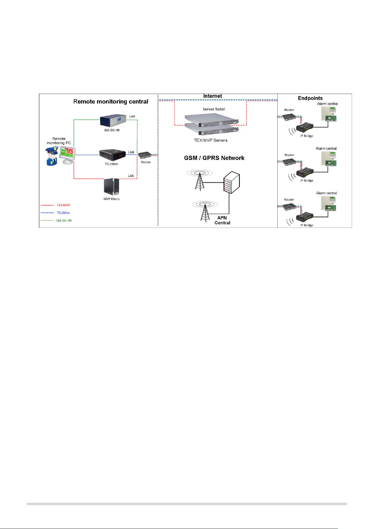
2 System operation
The IP Bridge transmits the signals of the alarm system connected to its simulated phone output and signals
generated on its inputs towards a TEX-MVP remote monitoring server, TELLMon or SIA DC-09 receivers via
wired internet. The route of the signals is illustrated in the following overview of the system. (Figure 1.)
Figure 1. Route of the signals
• Connection with servers/receivers
The module keeps alive the connection with the servers/receivers by sending periodic signals to their IP
addresses. If the connection with any of the IP addresses is lost the device attempts to reconnect at least once
per minute.
• Event sending/Acknowledgement
Events are sent to all preset IP addresses at the same time. The module acknowledges the event towards the
monitoring station if it receives at least one ACK from any of the preset IP addresses. The same rule is applied
to the module’s internal events. Regardless the acknowledgement it continues to report the event to the rest of
the IP addresses. If it doesn’t receive an ACK from an IP address it attempts to report the event in every 10
seconds via LAN or in every 20 seconds via mobile internet for up to 10 minutes. If the event couldn’t be
reported for 10 minutes for all the preset IP addresses, the module stops trying. This event won’t be reported
again, but it will be in the module’s event log. If any of the inputs is activated when a power failure occurs, an
event will be generated again when the power comes back.
Page 5
T. E. L. L. SOFTWARE HUNGÁRIA KFT
5
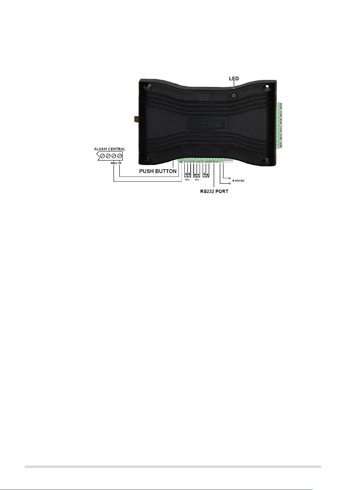
3 Wiring
Figure 2. Wiring diagram
• Wiring alarm central
Connect the alarm central’s telephone line input to the module’s „LINE” terminals.
• Wiring contact inputs
Connect the inputs accordingly to the configured control mode, normally open (N.O.) or normally closed (N.C.).
• Wiring outputs
The outputs provide potential free, normally open (N. O.) contacts, please use them accordingly. Pay attention
to the maximum loads supported by the outputs, which is 1A @ 12V DC by output! In case of higher load or
higher voltage please use an external relay!
Page 6
T. E. L. L. SOFTWARE HUNGÁRIA KFT
6
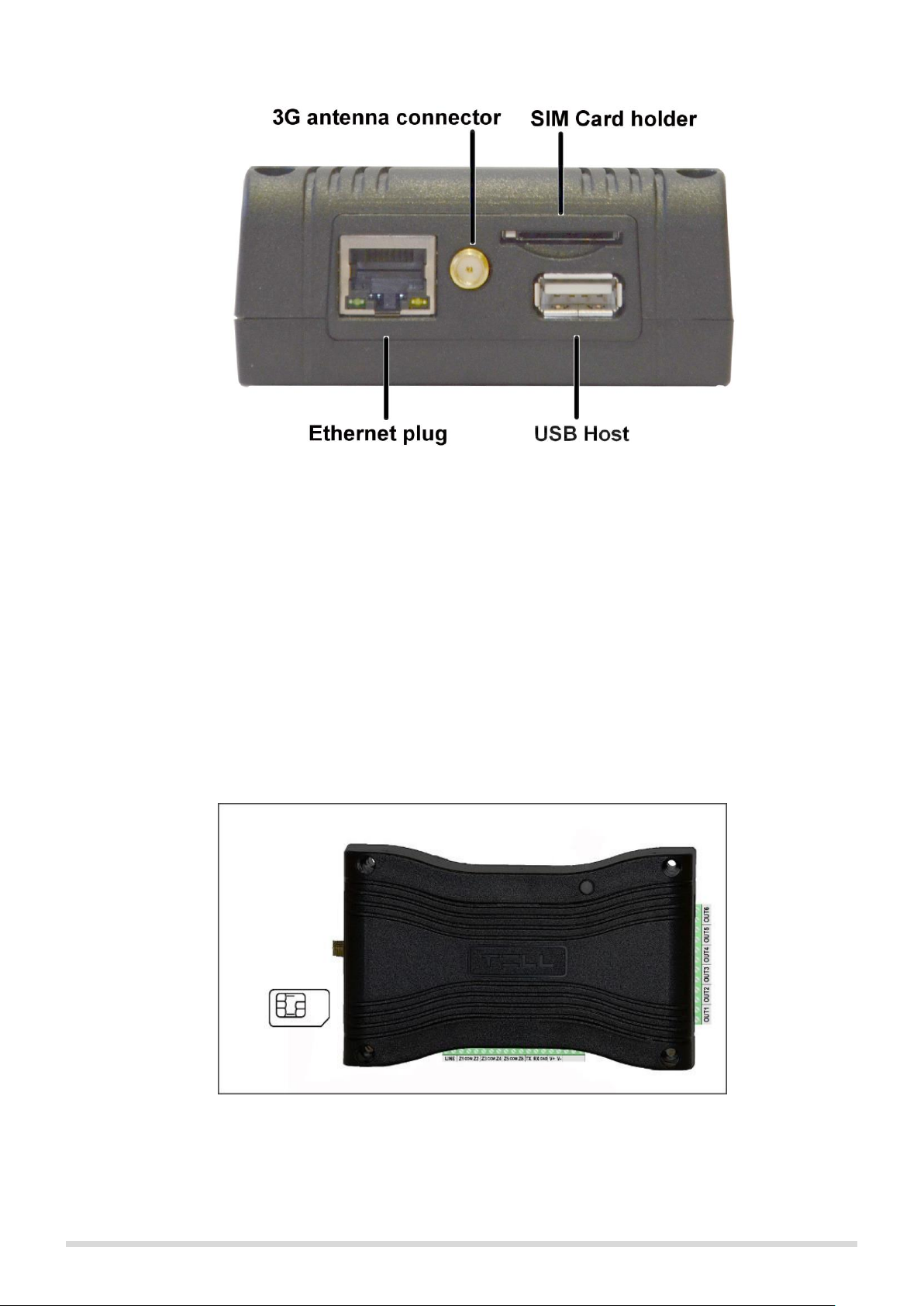
• Connecting Internet
Connect the local internet network cable (LAN) coming from the router to the Ethernet connector of the IP
Bridge.
• Wiring antenna
If the module has a 3G modem, use the 3G antenna connector to wire the antenna.
• SIM card holder
If the module has 3G modem, insert the SIM card into the card holder according to Figure 3. below and push it
until it clicks. If you want to remove the SIM card, just push the card again.
Figure 3. Inserting SIM card
• Network configuration
The module’s network is configurable through the USB Host with a pendrive.
Page 7

T. E. L. L. SOFTWARE HUNGÁRIA KFT
7
The connectors on IP Bridge panel
LINE
Simulated telephone line for connecting alarm panel
Z1
1. contact input (considered between Z1 and COM)
COM
Common terminal between Z1 and Z2 contact inputs
Z2
2. contact input (considered between Z2 and COM)
Z3
3. contact input (considered between Z3 and COM)
COM
Common terminal between Z3 and Z4 contact inputs
Z4
4. contact input (considered between Z4 and COM)
Z5
5. contact input (considered between Z5 and COM)
COM
Common terminal between Z5 and Z6 contact inputs
Z6
6. contact input (considered between Z6 and COM)
TX
RS232 serial port TX
RX
RS232 serial port RX
GND
RS232 serial port GND
V+
Supply voltage 9-30V DC
V-
Supply voltage negative polarity (GND)
Outputs
OUT1
1. relay contact output, normally open (N. O.)
OUT2
2. relay contact output, normally open (N. O.)
OUT3
3. relay contact output, normally open (N. O.)
OUT4
4. relay contact output, normally open (N. O.)
OUT5
5. relay contact output, normally open (N. O.)
OUT6
6. relay contact output, normally open (N. O.)
4 Setup the alarm control panel
Check the followings on the alarm control panel you connected the IP Bridge module to:
• Contact-ID communication format has to be set in the alarm control panel.
• The alarm control panel must be configured for communication to monitoring station as it were using a
wired phone line.
• Set the dialing to TONE mode.
• Regardless the dialed phone number the IP Bridge emits the handshake signal and receives the Contact
ID events.
Page 8

T. E. L. L. SOFTWARE HUNGÁRIA KFT
8
5 Installation, setup
Attention! Do not mount the device in places where it can be affected by strong electromagnetic interference!
Do not mount the device in wet places or places with high degree of humidity!
After mounting and connecting the local internet the device can be powered up. Setting up the module can be
done through an internet browser from any computer that is connected to the same local network as the device
is. By default, the module is set to use DHCP, so IP address will be assigned to it by the local router.
Use the IP Bridge Virtual Client program, which can be downloaded from www.tell.hu website, to find the
modules' IP Addresses. In this case you need to enter into your browser the IP address of the device you'd like
to manage (e.g. pl.: 192.168.1.198). The web based interface uses port 80.
Using IP Bridge Virtual Client program
Figure 4. IP Bridge Virtual Client
• Launch the program on a computer that is connected to the local network
• select the adapter from the Discovered network adapters list (It is important to select an adapter that
is located on the same network as the IP Bridge.)
• click the Search button
• the program detects the IP Bridge devices connected to the network and lists them (see Figure 4.)
• enter the found IP address into your browser
The displayed device list contains the following details:
IP: the module’s IP address
MAC: the module’s MAC address
TEX: the module’s TEX group code and also the device’s ID (this can be modified later in the settings)
If the IP Bridge Virtual Client is unable to detect the module on the network, the UDP Broadcast service is
disabled on the router. Since the IP Bridge uses DHCP by default, in this case, you can find the module's IP
address in the DHCP list of the router.
Page 9

T. E. L. L. SOFTWARE HUNGÁRIA KFT
9
Getting the module's network address using a pendrive:
Insert a pendrive into the module’s USB Host connector. The module creates the export folder and adds the
macaddress.cfg file (e.g.: "export/A2225C7D806B.cfg") that contains the network settings. Once the file has
been copied, the LED turns red and the pendrive can be removed.
The USB drive can be 2.0 or 3.0 and the file system can be NTFS, FAT32, ext2 or ext4.
The file content has the following details:
PLUGGED=1 // the module is connected to the network
TYPE=dhcp // the network type is DHCP
MAC=A2:22:60:E0:ED:79 // MAC address of the module
IP=192.168.1.91 // IP address of the module
GATEWAY=192.168.1.1
NETWORK=192.168.1.0
SUBNETMASK=255.255.255.0
DNS1=tellsofthun.local
DNS2=192.168.1.2
DNS3=8.8.8.8
5.1 Service ports
The following ports are used by IP Bridge module:
80 http web based interface
443 https web based interface
22 SSH – technical support
5.2 Router settings
If you’d also like to use the module’s web interface through the internet, set up on your router the port
forwarding of port no. 80 and port no. 443 at the module’s IP address. If it is enabled in the module settings,
then loading the web interface through port no. 80 (http://192.168.1.110) redirects to port no. 443
(https://192.168.1.110). In case the port no. 443 is already taken or forwarding of this port is not possible, you
can also use a different one, but in this case open the page directly through https protocol (e.g.:
https://192.168.1.110:8443). If you need the technical support’s help to solve any issue, you’ll need to open
and forward port no. 22.
5.3 Network configuration
Some of the module parameters can be set and modified with a text file on a pendrive. You can use USB 2.0 or
USB 3.0 pendrives with NTFS, FAT32, ext2 or ext4 file system on it. To modify the network settings create the
import/macaddress folder (pl.: import/A2225C7D806B) on the pendrive. Within this folder create the
ipbridge.dnr file, that contains the settings.
The following settings can be added to the config textfile (the values and IP addresses below are only
samples!):
ADDRESS="192.168.1.198" : to set the static IP address
NETMASK="255.255.255.0" : to set the netmask for the IP address
NETWORK="192.168.1.0" : to set the default subnet
GATEWAY="192.168.1.1" : to set the gateway for the static IP address
DNS1="8.8.8.8" : to set DNS1 for the static IP address
DNS2="208.67.220.220" : to set DNS2 for the static IP address
ADDRESS="dhcp" : to restore DHCP mode
Page 10

T. E. L. L. SOFTWARE HUNGÁRIA KFT
10
You can leave the unused settings in the configuration file, in this case mark them with a # character at the
beginning of the line, so that the module ignores them (e.g.: #ADDRESS="dhcp").
Important! In the created file add an ENTER at the end of each line and make sure that it doesn’t
contain any further whitespaces (tab, space, etc.).
Configuration sample:
If the A2225C7D806B MAC address was read from the module the path is the following:
import/A2225C7D806B/ipbridge.dnr
If you want the module to use 192.168.1.115 static IP, the 255.255.255.0 netmask, the 192.168.1.0 subnet,
the 192.168.1.1 gateway, the 8.8.8.8 DNS1, the 208.67.220.220 DNS2, the content of the textfile must be
as follows:
ADDRESS="192.168.1.115"
NETMASK="255.255.255.0"
NETWORK="192.168.1.0"
GATEWAY="192.168.1.1"
DNS1="8.8.8.8"
DNS2="208.67.220.220"
To apply the settings in the configuration file insert the pendrive into the module’s USB Host connector. The
module reads the settings from the file. The pendrive can be removed, when LED1 turns red. After removal
LED1 turns green, the module applies the new settings then reboots. After restarting the LED1 is green.
Page 11
T. E. L. L. SOFTWARE HUNGÁRIA KFT
11
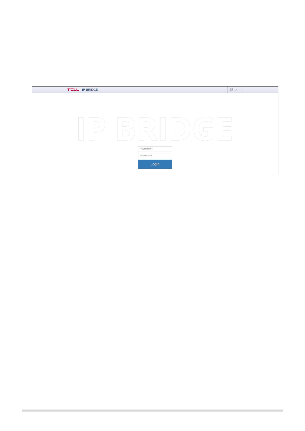
6 Web based interface of IP Bridge
Enter the module’s IP address into your browser to open the web intarface (e.g.: 192.168.1.198) and enter the
username and password for login (see Figure 5.). To access the interface via Internet, enter into your browser
the router’s external IP address followed by the port number you’ve forwarded (e.g.: 93.189.143.72:8181). In
case the https redirect is enabled in the module, after connecting through http (port no. 80) automatically
redirects to https (port no. 443).
Figure 5. Login
The default login credentials are:
Username: admin
Password admin
After the first login change the default passwords.
To add and manage additional users, the module has RADIUS server support that can be set in the „RADIUS
server” section of the „Settings” menu.
If you enter incorrect username or password several times, the module will block the login from your IP address
for the duration that is set in the settings. The default setting blocks the login for an hour after 5 incorrect login
attempts.
After signing in, when you modify any module setting a red bar at the top of the page warns you to save the
changes. There is no functional difference between the Save and Cancel buttons at the bottom of the page and
on the warning bar.
Page 12
T. E. L. L. SOFTWARE HUNGÁRIA KFT
12
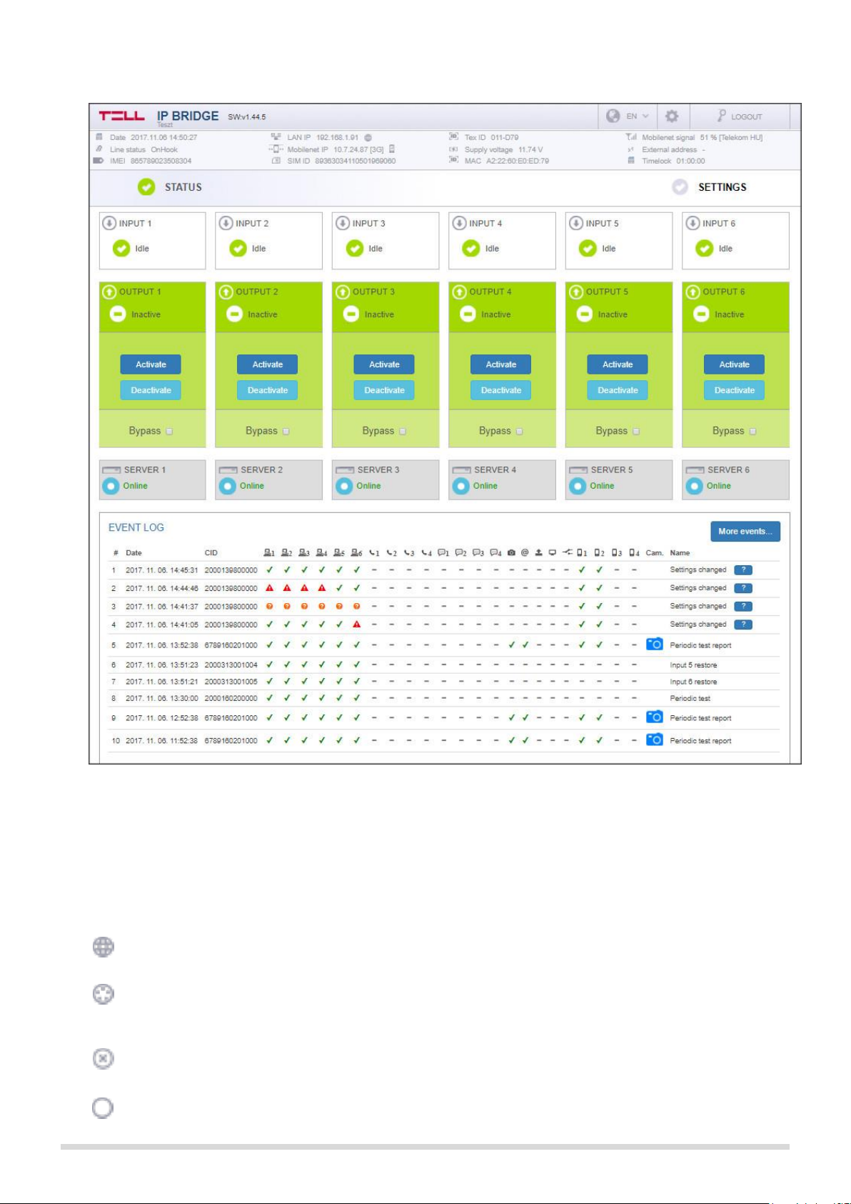
6.1 Module status
Figure 6. Module status
The module displays the module status page after login (see Figure 6.). In the header the basic status
information is displayed: the module’s date/time, current LAN IP address, supply voltage, the module’s remote
monitoring group ID and device ID and the simulated phone line status. In addition, if the IP Bridge has an
extension panel, the mobile internet’s IP address and signal strength in percentage are also here.
The icon next to the IP address indicates the status of the connection:
Internet connection is OK. There’s a Ping server set in the Settings to verify the internet connection and
the module reaches it.
Intranet connection is OK. There’s a Ping server set in the Settings to verify the intranet and it can be
reached by the module. (This icon is displayed, even if there’s also set a ping server to verify the internet,
but that one can’t be reached by the module.)
There’s no Internet connection. There’s a Ping server set in the Settings to verify the internet
connection, but the module can’t reach it.
Network connected. LAN cable is connected to the module, there is an IP address, but there’s no ping
server set.
Page 13
T. E. L. L. SOFTWARE HUNGÁRIA KFT
13
Unknown network. LAN cable is connected, there’s ping server set (internet, intranet or both), but none
of them can be reached.
No connection. This icon indicates that the module is starting or there’s no LAN cable connected.
If the device has an extension module, the following icons can be displayed next to the Mobileinternet IP
Address:
Internet connection is OK. This icon is displayed if the module has a mobile internet IP but no Ping
server is set or if there’s a Ping server set in the Settings to verify the internet connection and the module
can reach it.
There’s no mobile internet connection: Also this icon will be displayed, if the module can’t connect to
the mobile network, or if a Ping server is set in the Settings, but it can’t be reached by the module.
The language of IP Bridge’s web interface can be set with the language icon on the right side of the
header.
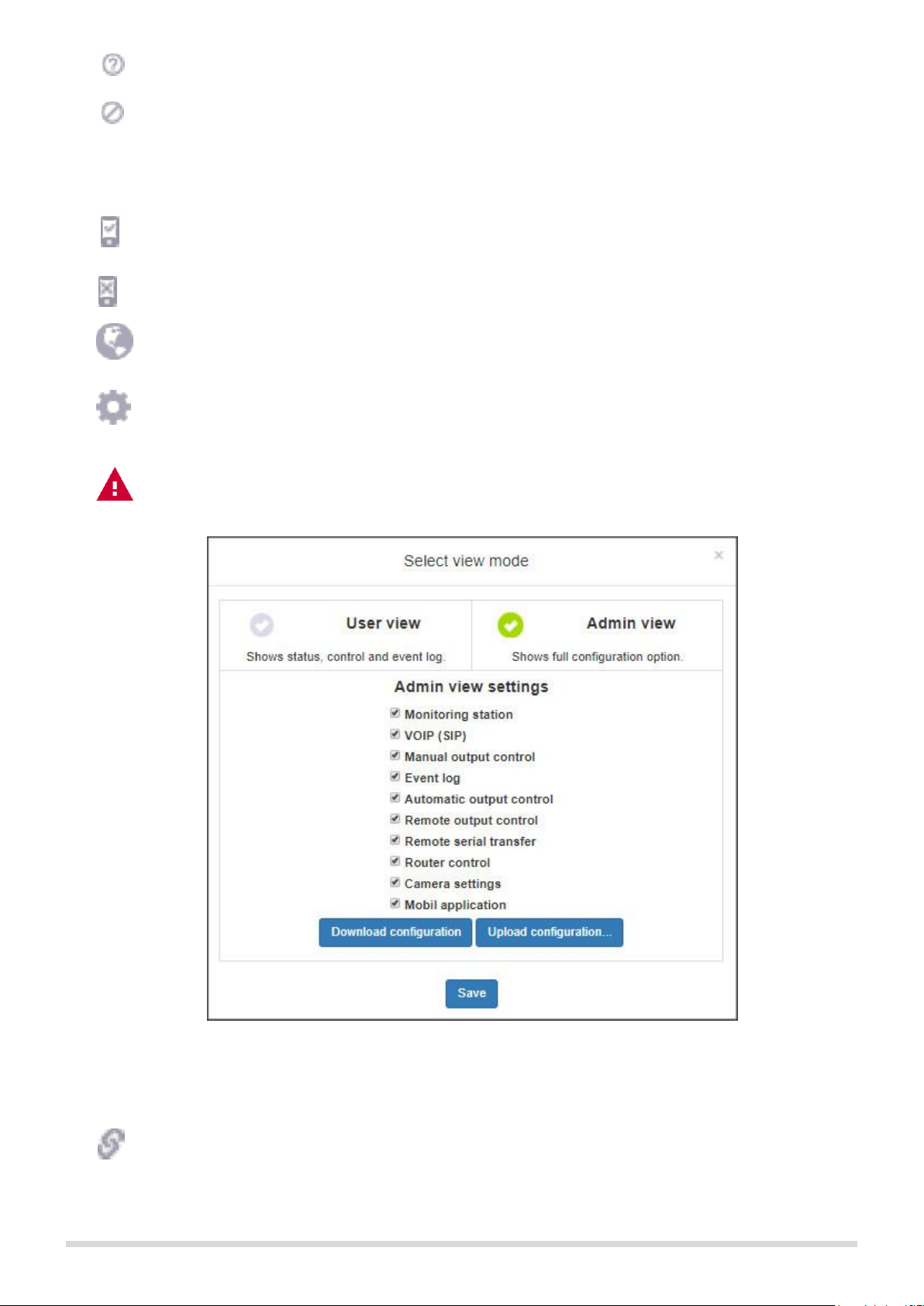
The „gear” icon opens the view mode selector window (Figure 7.) where you can also customize the
selected view, to display only those menu items that are needed. Here you can also download the
configuration to make a backup of your settings, or you can also upload a previously saved one.
Attention! The saved configuration file contains sensitive data. Please store it accordingly.
Figure 7. Select view mode
Line log: By clicking the icon next to the „Line status” opens the Line log window (Figure 8.), which
allows you to monitor the alarm control panel’s communication. Here you can export the incoming data
into a csv file or copy them to the clipboard.
Page 14

T. E. L. L. SOFTWARE HUNGÁRIA KFT
14
Figure 8. Line log
Input section: you can check the current state of the module’s zone inputs:
Idle / Active / Sabotage
Output section: you can check the current state of the outputs and also remote control them
Output status: Inactive/Active
Output control: outputs can be remote controlled with the Activate/Deactivate
buttons.
Control with events: the automatic control of an output can be enabled or
disabled with the bypass checkbox (e.g.: because of a malfunctioning sensor the
output can be disabled.)
Servers section: you can check the connection with servers/receivers here. The connection status
can be:
Not configured: the IP address and/or port is not set
Checking…: booting, checking in progress
Connecting…: connection is in progress
Authenticating…: authentication is in progress
Online: successful connection
Offline: the server/receiver is unavailable.
If the module is continuously trying to authenticate, it is likely that bad but existing
IP address/port is set or the receiver on the IP address is incompatible with the IP
Bridge module.
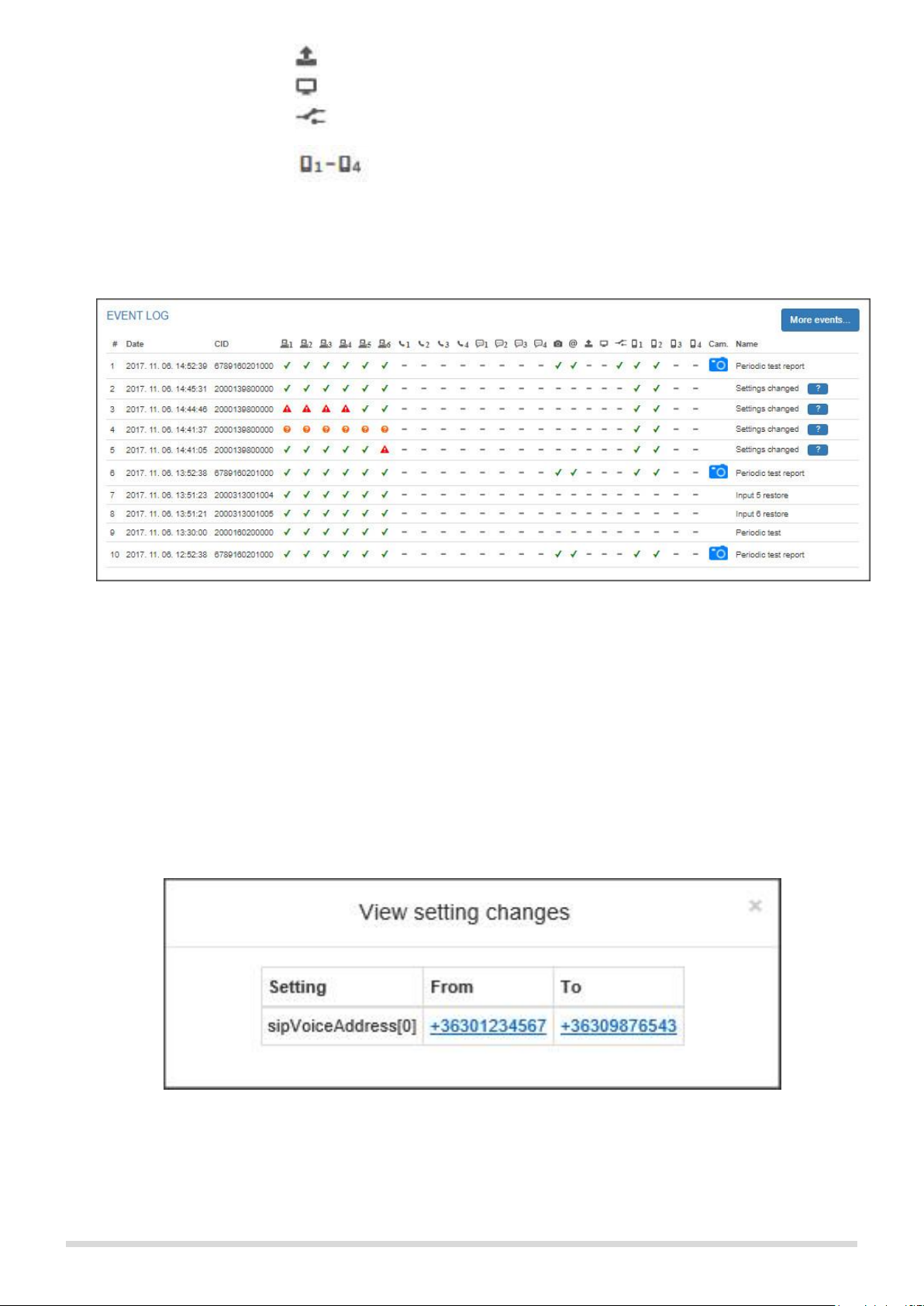
Event log: The Event Log (Figure 9.) shows the events received from the alarm control panel
through the simulated telephone line and also the internal events of the module.
The module stores the past 500 events. The list always contains the last 10
events.
Date/time: date and time of the event
CID: the event’s Contact ID code
: indicates whether there was notification sent to the IP address of
S1…S6 server/receiver
: indicates whether there was V1-V4 phone number notified via VOIP
voice call
: indicates whether there was M1-M4 phone number notified via SMS
: the status of saving the camera images associated with the event
: the status of sending emails associated with the event
Page 15
T. E. L. L. SOFTWARE HUNGÁRIA KFT
15
: the status of uploading camera images to an FTP server
: the status of displaying event in TMS
: the status of relay control associated with the event
: indicates whether push message was sent to A1-A4 smart device
Cam.: If a camera image is associated with the event a camera icon appears in
this column. By clicking on the icon the camera images can be viewed in a popup
window.
Figure 9. Short event log
Name: This is the name of internal events or events received on telephone line.
There’s a „?” icon next to the „Settings changed” events, which are generated
when any of the settings are updated. Clicking on this icon you can check which
setting was changed and what were the old and new values. (see Figure 10.). If
any sensitive information (e.g. password) has changed, it will not appear in the list
of changes. If only sensitive data has been changed, the question mark icon will
not be displayed.
Figure 10. Setting changes
Page 16
T. E. L. L. SOFTWARE HUNGÁRIA KFT
16
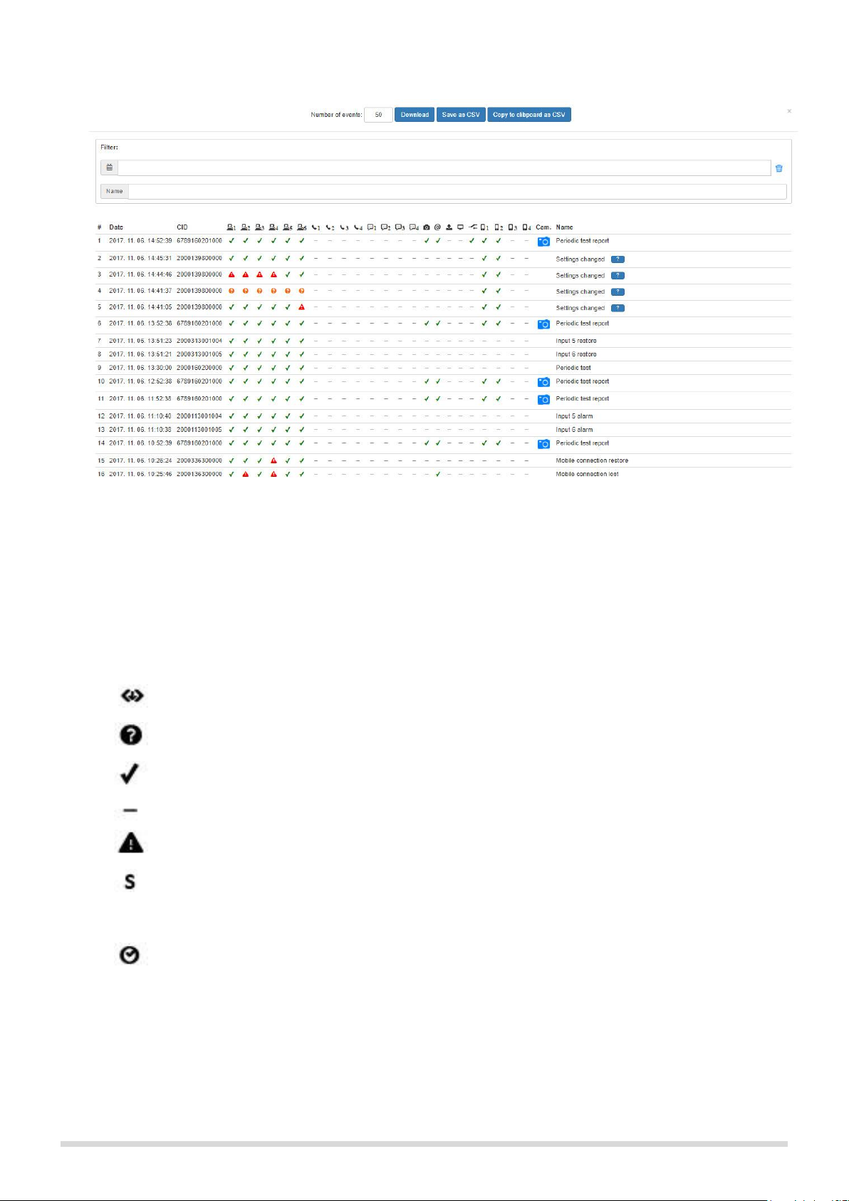
More events: The button opens a popup window where you can filter the events
stored on the module (Figure 11.).
Figure 11. More events
Download: Downloads the set number of events stored in the module.
Save as CSV: The downloaded list can be saved in CSV format.
Copy to clipboard as CSV: The downloaded list can be copied to clipboard in
CSV format.
Filter: Events can be filtered by date range and event name.
The meaning of signs in the columns:
: new event was created and added to the notification queue
: event sending in progress
: successful event sending
: server/receiver IP address is not set
: the signal couldn’t be sent (e.g.: server is not available)
: server connection ok, but no receipt was received
(serial port or connection failure at the monitoring station)
: Time out, event couldn’t be sent within 10 minutes.
In the „More events...” window camera images and details of setting changes associated with the events are
available just like in the short event list:
Page 17

T. E. L. L. SOFTWARE HUNGÁRIA KFT
17
6.2 General settings
Figure 12. General settings
Page 18
T. E. L. L. SOFTWARE HUNGÁRIA KFT
18
You can configure the communication and operation settings on the „General” tab within „Settings” (Figure 12.).
Device name: This is the unique name of the device that is displayed in the website’s header.
Account ID: The client identifier used for remote monitoring. This ID is used only for transmitting the module’s
internal events. The external module events are forwarded with the ID that is received from the alarm system.
TEX ID:
Group ID: This is the monitoring station's ID in hexa format. If you don't have a Group ID, please contact
your reseller.
Device ID: This is the module's 3 characters long ID in hexa format. The valid characters are 0...9, A, B,
C, D, E, F.
Input event limit: This setting limits the number of events being taken into consideration in the selected period
of time. The limitation will be applied by input, but will affect all the inputs. After the limitation period has
elapsed, the event becomes again enabled and can generate an alarm. The limitation period can be set
between 1 and 99 hours. With this setting the repeating alarm caused by malfunctioning sensor can be
avoided. In this case the output controlled by the event won’t work either.
Users: In default there’s one user with administrator level rights and one user with user level rights. Their
username and password can be modified.
RADIUS server: Server access settings for adding and managing additional users.
Server: The IP address of the radius server.
Port: The port of the server. The default port is 1812.
Secret key: Encryption key for authentication.
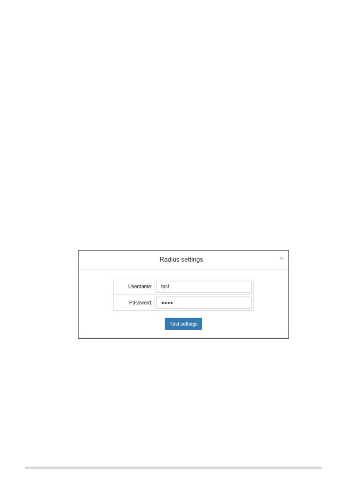
Modify radius settings: In the popup window (see Figure 13.) you can update the settings for Radius
server connection. The connection data can be saved only after a successful test, so you can’t lock
yourself out of the module.
Figure 13. Radius settings
Show admin and user password: Passwords will appear but will be hidden again after saving your
changes.
Device language: Language of report sending.
Device time:
Device timezone: The proper time zone setting is necessary for the scheduled report sending via email
and for creating periodic test reports.
Synchronization:
NTP server: In the popup window you can enter and test 2 NTP servers.
Mobile application server: Time can also be synchronized through the TELL server. If you chose
this option, you must enable the server connection. If it is not yet enabled, press the Advanced
Settings button to be redirected to the appropriate settings.
Page 19

T. E. L. L. SOFTWARE HUNGÁRIA KFT
19
Manual: If you do not have access to the Internet or you can not access the NTP or the TELL
server through the network, you can manually enter the date and time.
The first day of the week: Setting up the first weekday is needed for the scheduled email sending.
Allow access through HTTPS: It can be enabled that the module redirect the requests to a secure HTTPS
connection.
Enable UPnP: The module can be enabled to use UPnP protocol. The UPnP service must be enabled in the
network’s router to work properly.
Default network: You can select default network for the services of the module, e.g. reporting towards
monitoring station, email sending, remote serial data transfer or VOIP calls. If the selected option includes the
mobile network communication, you can enable with the checkbox the image uploading via mobile internet as
well. If the module doesn’t have an extension panel LAN will be the default network.
Ping servers: Ping servers can be set for checking internet and intranet. If the module has an extension panel,
monitoring the mobile internet connection is also possible. Two IP addresses can be set for each network type.
Server selector: You can select predefined servers from the drop-down list, or you can also specify
„Custom„ servers, in which case IP address 1 and 2 fields become editable.
Ping interval: sending frequency in seconds
Retry interval for failed ping: ping attempt frequency if ping failed
Number of failed ping attempts for generating connection lost event: After the specified number of
failed ping and external event is generated about the failure.
Logoff timeout: If there’s no activity for the time set here in minutes, the website will automatically log off.
Ban time: The user won’t be able to login from an IP address for the time set here, if there was specified
amount of failed login from the same IP address within the specified period of time. If 0 minute is set, the user
won’t be banned for failed login.
SIM PIN: If the module has an extension panel you can enter the SIM PIN here. If the SIM PIN is switched off,
the module ignores the content of this field. The module tries a PIN code once if there are still 3 attempts. If
there was a failed attempt before, a „Wrong SIM PIN” event is generated and you need to remove the SIM card
from the module and unlock it by inserting it into a mobile phone and entering the correct PIN code.
Battery: If the supply voltage falls below the alarm threshold and remains there for at least 30 seconds a
„Battery fault” internal event is generated. If the supply voltage returns above the alarm threshold and remains
there for at least 30 seconds a „Battery restore” internal event is generated.
APN: If the module has an extension panel, enter the Internet access point name (belongs to the SIM card, it is
provided by the mobile service provider).
FTP/SFTP: The module is able to upload the camera images captured during an alarm to an FTP server.
Select the protocol type from the dropdown list (FTP/SFTP)
Enter the IP address of the FTP Server and also the port number if necessary separated by a colon
(e.g.: 192.168.1.1:8181)
The path of the image folder can be also set.
The last 2 fields are for the username and password required for the connection.
TMS server: The module is able to send not only the Contact ID code to the TMS user monitoring station but
also the captured camera images and the live stream URL of the cameras. To set this enter the server’s IP
address, the port number and select your network preferences. If there are IP cameras set in the module and
these cameras are associated with an event, the necessary details will be automatically sent towards the TMS
server in case of an alarm.
Update server: If the Firmware update server is not set, in default the module downloads the firmware update
from the server provided by the manufacturer.
Firmware update: To get a notification about the updates, enter your email address. You can select from the
dropdown, whether you only want to get the notification about the update, or you also want the update to be
Page 20

T. E. L. L. SOFTWARE HUNGÁRIA KFT
20
automatically downloaded. And if so, you can also decide to allow downloading on mobile internet as well, or
only on LAN. The time of update checking also can be edited. Select from the available updates and then you
can get info about it with „Release notes” button or start the firmware update with „Update now” button.
6.3 Servers
Figure 14. Servers
In the Servers menu item (Figure 14.) you can configure the data needed for the connection to remote
monitoring servers. The module can send signals to 6 different servers simultaneously.
#: the index of the server
Server name: You can name the receiver
Server IP: The receiver’s IP address or domain name
Port: Port number for the IP address
Network: Use the dropdown menu to set the communication channel for the device to access the remote
monitoring receiver, and also select the backup communication channel. (If the module doesn’t have an
extension panel, only the LAN can be selected.)
Receiver: The receiver’s type can be selected from the dropdown which also fills the port number with the
default value. (If not the default port is used by the receiver, it can be manually updated). The selectable
receiver types are: TEX/MVP (TCP), TELLMon (TCP), TELLMon (UDP), SIA IP (TCP), SIA IP (UDP)
Enable test: Test report sending towards the given server can be enabled or disabled.
Test interval: Test report sending frequency in seconds. The module sends test report with the frequency set
here to check the connection with the receiver at the given IP address.
Page 21

T. E. L. L. SOFTWARE HUNGÁRIA KFT
21
Attention! Make sure you do not specify the same server with external and local IP as well, because in
this case the transmission will not work properly.
Configuration example
From the servers up to 6 server groups can be created, which can be assigned with events later. By
creating groups, you can separate alarm events from technical events for example. In each server group
you can set which servers are primary and which are backup.
Figure 15. Server groups
Servergroup name: You can give a name to each server group. (e.g..: Alarm, Technical issues)
#: Index number within the group
Server: You can assign a server to a group by selecting it from the dropdown menu.
Primary server: Set with the checkbox which server is primary and which is backup. There can be more than
one primary server. The signal will be sent simultaneously to each of them. The signal will be sent to the
backup servers only if none of the primary servers were available. If there are multiple backup servers, the
module sends the signal to them in order.
Add server: You can add server to a group by selecting the servergroup and
pressing the „ADD MORE” button at the bottom of Servers page.
Delete server: Use the dust bin icon next to the server to delete it from the group.
Page 22

T. E. L. L. SOFTWARE HUNGÁRIA KFT
22
6.4 Cameras
Figure 16. Cameras
By clicking the Cameras menu, IP Bridge automatically finds and lists IP cameras that support the ONVIF
recommendation and are connected to the same network (Figure 16.).
Figure 17. IP Camera settings
Clicking the „Profile dependent parameters” IP Bridge lists the profiles that are set in the camera (Figure 17.).
Usually, the difference between these profiles is the resolution.
The links of the found profiles (both the Snapshot URL and Stream URL) can be copied and tested.
Pressing this button displays in a popup window a snapshot of the camera using the profile settings.
This makes easier to identify and select the profile.
Page 23

T. E. L. L. SOFTWARE HUNGÁRIA KFT
23
If the IP camera doesn’t have the password-free connection enabled, IP Bridge can’t automatically sign in to
get the configured profiles. In this case, the „Profile dependent parameters” button allows you to enter the
username, password and the ONVIF port on which the IP Bridge can communicate with the camera.
The „Add to list” button adds the given camera to the camera list of the IP Bridge and fills the required
parameters (Figure 18.). When you are auto-filling, you can enter a unique name for the camera which will be
displayed in the Events menu item.
Figure 18. ONVIF IP camera URL
To edit the URL click the “View/Edit” button. In the pop-up window (Figure 19) you can edit the URL you’ve
previously set, manually add a new camera URL or display the image of a previously set camera.
Figure 19. Edit Camera URLs
Local Snapshot and Stream URL:
The module saves snapshots of configured IP cameras, so if an event occurs, it sends these saved images as
attachments by email, uploads it to an FTP server, or sends it to the TMS system.
External Snapshot and Stream URL:
The module is able not only to store the images, but also to send the camera links in a Push message for the
smartphone application. So in case of an event, even the live image can be viewed in the application. In this
case, you need add your camera with its external link.
Attention! Depending on the camera resolution, the SD card may be full after 5-10 thousand events for
which camera recording is required. In this case, the device can not store additional camera images
until the previously recorded images are deleted. You can do this in the Cameras menu.
Page 24

T. E. L. L. SOFTWARE HUNGÁRIA KFT
24
Managed saved snapshots:
The module stores the camera images recorded during the events on the SD card. This menu item provides
information about the total size of the saved images (Figure 20.) The images can be archived, downloaded or
permanently deleted from the module.
Figure 20. Saved camera images
Capacity: Size of the SD card inserted into the module
Saved snapshots’ size: The size of the saved images in MB and the percentage of the used space.
Free space: The free space on the SD card in MB and in percent.
Manage saved snapshots: The images can be deleted, archived or downloaded here. These buttons open a
popup window.
Figure 21. Manage saved snapshots
Page 25

T. E. L. L. SOFTWARE HUNGÁRIA KFT
25
6.5 VOIP
Figure 22. Setting VOIP phone numbers
The module provides voice call service via VoIP through the internet. For voice call notification enter the SIP
server’s IP address, username and password.
The magnifier icon opens a popup window (see Figure 23.), where you can select your VoIP
provider.
Figure 23. VoIP providers
Page 26

T. E. L. L. SOFTWARE HUNGÁRIA KFT
26
By selecting the service provider, the device automatically fills out all necessary information, you just need to
add the username, password and SMS sender phonenumber.
If you can’t find your provider in the list, select the ’Custom’ option. In this case you need to add manually all
the details.
SIP server: The SIP server’s IP address.
SIP user: The username that belongs to your VoIP subscription.
SIP password: The password that belongs to your VoIP subscription.
SMS sender: This phone number will be displayed as SMS sender.
SMS URL: The provider’s SMS URL
Voice call V1-V4: 4 phone numbers can be added, which (according to the event settings) can be reached via
voice call if an event occurs.
Phone number or SIP address: In this field, you can set the phone number or SIP address for internet call. If
the SIP server is set up and the account has credit, so it is topped up with money, the module can call phone
numbers as well, else it can start only internet call and in this case only the SIP address is needed.
SMS 1-4: 4 phone numbers can be added. The preset SMS messages can be sent to these numbers if an
event occurs (according to the event settings).
Test voice call now: If a SIP account is set, you can start a test voice call to the given number.
Send Test SMS now: If a SIP account is set, you can send test SMS to the given number.
Note:
Voice over Internet Protocol – commonly known as VoIP, Voice over IP or IP telephony – is a methodology and group of technologies
for the delivery of voice communications over Internet Protocol (IP) networks, such as the Internet. Since the IP network doesn’t
guarantee that data packets are not lost, are delivered in sequential order or any other Quality of Service (QoS) criteria, VoIP
implementations may face problems like the data packets’ basic delay and the delay resultant from packet reordering and also data
loss. The basic data delay depends on the distance of the partners within the network, the route of packets and the load on the
network. The reordering of data packets depends on the VoIP service provider too. If you are experiencing bad voice quality during
the call, it is advisable to try a voice call with a different VoIP service provider.
Page 27

T. E. L. L. SOFTWARE HUNGÁRIA KFT
27
6.6 Mobile application
Figure 24. Mobile application settings
In the „Mobile application” menu item you can set the server data required for Push message sending and also the
devices that can be assigned with the module.
Enable: this service can be enabled/disabled here.
In default the server setting fields are filled with the data of manufacturer's server reserved for this purpose, which are the
followings:
Server IP: 54.75.242.103
Port: 2020
Network: The drop-down menu allows you to set the communication channel for the device to access the
server and whether it has a backup communication channel. (If the module doesn’t have an extension panel,
only LAN can be selected.)
When adding an application, clicking the update button displays application data.
4 mobile devices can be registered for the module. Each slot has a uniqe identifier that can be displayed by
clicking the QR code button at the end of the line. In the mobile application you can register a device into the
module by scanning the QR code of the given slot. After the registration the mobile application’s ID and the
mobile device’s name are listed here.
Page 28

T. E. L. L. SOFTWARE HUNGÁRIA KFT
28
6.7 Event settings
Figure 25. Event settings
The module internal and external events can be configured on the Events tab of Settings menu item.
Event name:
IN1… IN6 alarm: new alarm events generated by external contact on input IN1… IN6 according to the (NO/NC)
input settings (alarms)
Sabotage alarm/ Sabotage restore: The sabotage (tamper) setting is applied to each input specified with EOL
option. The module will automatically enter the number of the violated zone (001...006) into the zone section of
Contact ID code. The module does not send tamper signals from non-EOL inputs.
Battery fault/ Battery restore: The module has a power monitoring function. A battery fault event is generated
if the supply voltage drops below 11.5V (or 23.0V) for at least 30 seconds. A battery restore event is generated
if the module’s supply voltage restores above 12.4V (or 24.4V) for at least 30 seconds. The thresholds are
configurable in the settings.
The following two internal events are generated depending on the settings. If there’s no Ping server set under
the Settings tab, regarding both the internet and intranet the connection lost and connection restore events are
generated when the IP Bridge gets an IP address on the network it is connected to. In this case the connection
lost or connection restore events are generated simultaneously for both the intranet and internet. If Ping
servers are configured to monitor the internet and intranet, the events are generated according to whether or
not the module has accessed server.
Internet connection lost / Internet connection restore: The connection lost event is generated when the
module is unable to connect to the network or if a Ping server is set up to monitor the internet but it can’t be
accessed. The restore event is generated when the module successfully connects to the network or it is able to
access the Ping server. If the connection error takes more than 10 minutes the notification time of the error
event expires, and only the restore event will be transmitted, but the module’s event log will list the error event
as well.
Page 29

T. E. L. L. SOFTWARE HUNGÁRIA KFT
29
Intranet connection lost / Intranet connection restore: The connection lost event is generated when the
module is unable to connect to the network or if a Ping server is set up to monitor the intranet, but it can’t be
accessed. The restore event is generated when the module successfully connects to the network or it is able to
access the Ping server. If the connection error takes more than 10 minutes the notification time of the error
event expires, and only the restore event will be transmitted, but the module’s event log will list the error event
as well.
Router warm restart: The module is able to warm restart certain type of routers on the same network the IP
Bridge is connected to (see Router control menu item). This event is generated when there’s no response to
the ping set on the Router control tab and the module restarts the router.
Router cold restart: The module is able to warm and cold restart certain type of routers on the same network
the IP Bridge is connected to (see Router control menu item). This event is generated if the warm restart set on
the Router control tab wasn’t successful and the module cold restarts the router.
Periodic test: The module is able to send periodic test reports towards the monitoring station.
The pencil icon next to the name opens a popup window (see Figure 26.) where you can set the time of
sending periodic test report.
Figure 26. Periodic test report
FTP backup failed: The module can upload the images from the cameras assigned with it to an FTP server,
which can be set on the General tab of Settings (FTP/SFTP section). This event is generated when the module
was unable to upload the images.
Not enough space: This event is generated when only 200 MB free space remains to store the images. If the
size of the images has reached the maximum, the module will not delete images and will not record new
images if an event occurs.
Settings changed: This internal event is generated when the settings are changed.
Mobil connection lost / Mobil connection restore: The connection lost event is generated when the module
has 2G / 3G extenstion module, but it is unable to connect the mobile internet or if a Ping server is set to
monitor the mobile network, but it can’t be accessed. The restore event is generated when the module
successfully connects to the network or it is able to access the Ping server. If the connection error takes more
than 10 minutes the notification time of the error event expires, and only the restore event will be transmitted,
but the module’s event log will list the error event as well.
Only 2G network available: This event is generated when the device has a 3G module, but 3G network is
unavailable at the location, so it can only connect to the 2G network. In this case the camera snapshot sending
won’t work, even if this option is enabled on the General tab.
3G network available: This event is generated when the device has a 3G module and the 3G mobile network
is available at the location.
SIM card removed: This event is generated when the device has a 3G module and the SIM card is removed
from the module.
SIM card changed: This event is generated when the device has a 3G module and the SIM card is replaced
with another one. The module stores the last SIM ID and when a new card is inserted it compares its SIM ID
with the stored value and if those are different this internal event is generated.
Page 30

T. E. L. L. SOFTWARE HUNGÁRIA KFT
30
Wrong SIM PIN: This event is generated if the device has a 3G module and PIN code is required to unlock the
SIM card, but the PIN code set on the General tab is wrong. The module tries a PIN code once if there are still
3 attempts. If there was a failed attempt before a „Wrong SIM PIN” event is generated and you need to remove
the SIM card from the module and unlock it by inserting in mobile phone and entering the correct PIN code.
External event: You can also set up to 20 external events in the module, which are Contact ID events received
on the simulated phone line. The event codes expected from the alarm center can be added to the event list
and for each code you can set the notification scheme based on which the module needs to report to a
monitoring station, send email, send SMS, etc.
You can add external events with the „Add more” button at the bottom of the
Events page. The button opens a popup window (see Figure 27.).
Figure 27. External event
When entering the event code, partition and zone, it is also possible to define an event group by using the „*”
character. If any hexadecimal digit is received from the alarm center instead of „*”, but the rest of the code is
the same as the one you entered, the given event will be reported. The module compares the event received
from the alarm center with the external events recorded in the table, and if there’s a match, reports the received
event according to the settings of the event found. The module checks the event by type, then by event code
and finally by partition and zone number. When adding an external event, it is possible to add all the Contact ID
codes, which is the default setting. In this case * must be left in each field and all the CID codes received on
the simulated phone line will be transmitted according to the settings.
Page 31

T. E. L. L. SOFTWARE HUNGÁRIA KFT
31
When adding an event you can select the event code from the predefined list. There are several options to filter
event codes (Figure 28.):
Figure 28. Filtering external events
Type: From the dropdown you can select New event (1), Restore (3) or Any (*).
Code: When you enter the 3 digits long CID code the result list is displayed. The „*” character can be used also
here.
Event name: The event list can be filtered also by the event name. You don’t need to add the full name, the list
is automatically filtered when you type.
You can delete an external event you have added by clicking the edit button next to the event. The pop-up
window appears (see Figure 29) and you can find the delete button next to the save button.
Figure 29. Delete/edit external event
Event custom name: Both the internal and external events can have a custom name, which is displayed in the
event log, email report and also on the Status page. The default name will be used if the event doesn’t have a
custom name. The module automatically uses the default meaning of their CID codes.
Page 32

T. E. L. L. SOFTWARE HUNGÁRIA KFT
32
There are several setting options for events, that can be found on the Events tab. All settings are grouped, and
you can switch between them by arrows. The settings are the followings:
Input properties:
Figure 30. Input properties
Input type: select the default state of the input
- NO: normally open (To generate an alarm event the „Z1… Z6” input has to be shorted to the „COM”
common terminal. The restore event is generated when opening this contact.)
- NC: normally closed (The „Z1… Z6” input has to be shorted to „COM” common terminal by default. Alarm
event is generated when opening this contact. Alarm event is generated when the input is shorted to
„COM” again.)
EOL: if enabled, tamper protection function is automatically activated for the given input. In this case the given
input must be provided with a 1kΩ end-of-line resistor at the end of the loop, directly at the controlling contact
Sensitivity: The status change of the given zone input is ignored if it is shorter than the value set here. Unit of
measure: millisecond (10… 99999)
Bypass: Both the internal and external events can be eliminated one by one if it is not needed or a failure has
occured.
Notifiy next: If the CID codes of multiple external events are overlapping each other but you want to send
notification about all of them independently, by selecting this checkbox the next event will be generated even if
the CID code corresponds to this event.
Configuration example:
We’d like to receive notification about open, close and bulglary events while we want all signals to be
sent to the monitoring station (see Figure 31.) as well. If we check bypass option and an open or close
event is coming from the alarm system, the module communicates the first event (e.g: email notification
with camera image and SMS sending) and also checks the next event code. If it doesn’t fit, the module
checks the next one. If it fits, the module executes the necessary actions. The module continues this as
long as there’s another external event or the „notify next” option is not checked.
Figure 31. Adding multiple external events
Use the arrows to modify the sort order of CID codes. The module always begins to evaluate the CID
code filtering in the given order.
Page 33

T. E. L. L. SOFTWARE HUNGÁRIA KFT
33
Event codes:
Figure 32. Event codes
Each internal event can be associated with a Contact ID code. Each one of them has a default Contact ID
code, but it can be modified (see Figure 32.).
CID code: 3 characters (0…9, A, B, C, D, E, F) long event code used for reporting to a monitoring station. (e.g.
130 = burglary; the restore event is reported with the same code)
Partition: the event’s partition number (00… 99)
Zone: the event’s zone number (000… 999)
Monitoring station settings:
Figure 33. Monitoring station settings
Server groups configured on the Servers tab can be associated with the events. It is also possible to assign
different server groups to the alarm and restore events.
Check the ENABLE REPORTING option to start reporting to a monitoring station.
Page 34

T. E. L. L. SOFTWARE HUNGÁRIA KFT
34
Email settings:
Figure 34. Email settings
The module is able to send email notifications about events. Just like the monitoring station settings, the email
settings also can be set up by events.
The edit icon opens a popup window (see Figure 35.) where you can set the email address, subject and
email body.
Figure 35. Edit email message
Enter the addresses into the Email addresses field. To add multiple addresses separate them by comma.
The Subject field is for the email subject.
Enter the email body into the Text field.
By pressing the Test button it is possible to send a test message to the entered addresses to verify that they
are correct.
The Save button saves the email settings then the fields next to the event will be refreshed.
The delete button deletes all the email settings of the given event.
Page 35

T. E. L. L. SOFTWARE HUNGÁRIA KFT
35
Camera settings:
Figure 36. Camera settings
The cameras configured on the Cameras tab can be assigned to the events. If the event occurs, the module
sends the last 5 images of the assigned camera to the corresponding e-mail address or uploads it to an FTP /
SFTP server or sends it to the TMS server.
Enable: the camera assignment can be enabled with a checkbox.
Camera: You can assign camera to the event by selecting it from a dropdown list which lists the camera names
you’ve set in the Camera name field of the Cameras tab.
Next to the camera dropdown menu, the email address is displayed that was assigned to the event in the E-
mail settings. Image uploading to FTP / SFTP or TMS does not need to be enabled, it is sufficient if they are
configured in General settings.
VOIP (SIP) settings:
Figure 37. VOIP SIP settings
You can also set up a voice call notification for the events. The phone numbers can be specified in the VOIP
menu.
V1-V4 select the phone number you want to be notified about the event occurance.
Acknowledgement: Select from the dropdown (see Figure 38.):
Page 36

T. E. L. L. SOFTWARE HUNGÁRIA KFT
36
No ack, #=stop: accepting the call confirms the alarm
event automatically; by pressing the # key on the phone
stops reporting to the further phone numbers.
*= ack, #=stop: the user must confirm the event by
pressing the * key on the phone, otherwise the module
recalls the number until the user confirms the alarm
event. Pressing the # key on the phone stops reporting
to the further phone numbers and confirms the event at
the same time.
Ack. upon call reject: the alarm event can be
confirmed by rejecting the call. In case of accepting the
call, this also confirms the event automatically and
reporting to the further phone numbers can be stopped
by pressing the # key on the phone.
Audio file: Select the audio file you want to be played during the voice call.
To configure press the edit button in the event’s row, which opens a popup window (see Figure 39.).
Figure 39. Edit audio list
Upload a new audio: It is possible to upload audio files with mp3 extension which are not longer than
1 minute. Pressing the button opens a file browser window so you can select the file you want to
upload.
Delete selected audio: To remove a previously uploaded audio select it and press the „Delete
selected audio” button.
Save: Select the audio file to be played during the voice call then save it.
Network: You can set the communication channel of VoIP calls for each event. It is possible to set for each
kind of events a different network than the default network selected on the General tab.
Setting up the first event you can choose to fill all the other rows with the same settings.
Figure 38. Acknowledgement
Page 37

T. E. L. L. SOFTWARE HUNGÁRIA KFT
37
SMS settings:
Figure 40. SMS settings
It is possible to add SMS notification to the events. The phone numbers can be edited on the VoIP tab.
SMS1-SMS4: Select which phone numbers you want to be notified about the event.
The pencil icon opens a popup window (Figure 41.) in which you can edit the SMS message. The maximal
length of the SMS can be 70 characters.
Figure 41. Edit SMS text
Save button saves the text for the event.
The delete button removes all the notifications set for the event.
Setting up the first event you can choose to fill all the other rows with the same settings.
Push notification settings:
Figure 42. Push notification settings
Page 38

T. E. L. L. SOFTWARE HUNGÁRIA KFT
38
You can set Push message sending for the events. The devices can be added in the Mobile application
menu.
MOBIL1 – MOBIL4: Select which devices you want to be notified via Push message about the event.
The pencil icon opens a popup window (Figure 43.) in which you can edit the Push message. The
maximal length of the message can be 70 characters.
Figure 43. Edit push message
Save button saves the text for the event.
The delete button removes all the notifications set for the event.
Setting up the first event you can choose to fill all the other rows with the same settings.
Page 39

T. E. L. L. SOFTWARE HUNGÁRIA KFT
39
6.8 Remote modules
Figure 44. Remote module settings
You can add up to 6 remote IP Bridge modules to your device. You can use them for transparent serial data
transfer or for controlling the remote devices' output as an effect of a local event. The settings are the
followings (Figure 44.):
#: The module’s index number
Name: Unique name can be set for each module.
IP: the module’s IP address (If the remote module is not on the same network enter the router’s IP address and
the external port. It is also possible to add DNS instead of IP address. You need to configure the port forward in
the router!)
Port: The device’s https port
Username: The username of device administrator.
Password: The password of device administrator.
Test: You can check your settings by clicking the test button.
Remote serial data transfer:
The following settings are required for the transparent serial data transfer.
Remote module: Use the dropdown to select the remote module you’d like to associate with the device to use
it for serial data transfer. Besides the six modules, you can also select the „Receive only” option. In this case
the device only forwards data received from remote modules to its serial port. This can work with any number
of remote modules and they don’t even need to be among the associated remote modules. Also, this option
must be selected if you use the module to program an alarm system through the IP Bridge Client program. If
you select from the six associated remote modules the device indicates the connection status.
Page 40

T. E. L. L. SOFTWARE HUNGÁRIA KFT
40
Connection type: You can select from the following two connection types:
Continuous IP connection: The devices are continuously connected to each other.
Connect, if necessary: The modules connect each other only for sending data. After the data is sent
they close the connection.
Timeout: In case of temporary connection this is the time the module waits after the last data was sent
or received before closing the connection.
Network: Use the dropdown menu to set the communication channel for the device to access the remote
module, and also select the backup communication channel. (If the module doesn’t have an extension panel
LAN is the only option to choose.)
Maximum data delay: The module collects the data received on its serial port. If there's no delay in receiving
data, after the amount of time set in this field the module sends the previously collected data to the remote
module.
With these values the response times can be adjusted according to the established serial connection. If the
maximum data delay is smaller, the device waits for fewer data and sends the packet to the remote module
sooner, so the device on the remote module’s serial port receives a quicker response.
Serial port settings: You can configure the serial port’s settings to meet the requirements of the selected
connection type.
For more detailed information on the remote programming of alarm systems, please see the Appendix.
Page 41

T. E. L. L. SOFTWARE HUNGÁRIA KFT
41
6.9 Outputs
Figure 45. Output configuration
On the Outputs tab you can configure the outputs (Figure 45.) and assign automatic control to them. The
options are:
#: Index of the output
Output name: Unique name of the output which is displayed in the Status menu next to the index number.
Default state: Select the output’s default state from the dropdown list. The module has 2 terminals for each
output. If you configure the output to NC the relay status changes to closed and it remains closed.
Adding control modules by internal event:
Use the „Add more” button to add new control module. In the new row you can
configure the output.
Event: The event can be selected from a dropdown, that lists all the internal and
external events configured on the Events page.
Target (Figure 46.): You can select which module’s output to activate due to the
specific event. By selecting the „Local” option, you can control the module’s local
outputs. The Remote 1-6 options referring to the modules added on Remote
modules page.
Figure 46. Target
Page 42

T. E. L. L. SOFTWARE HUNGÁRIA KFT
42
Output: The target module’s output. In case it has a unique name, it is also displayed in the dropdown, else it
is listed by its sequence number.
Delay (sec): The delay of activating the output can be defined in seconds.
Output mode (Figure 47.):
State change: the event will cause a relay status change.
ON - Timed: the event activates the relay output for the time set in Time
field in seconds. When the time is up the output becomes inactive again.
ON - Permanent: the event activates the relay output permanently (the
relay output remains active until switching off or receiving status change
command).
OFF: the event deactivates the relay output.
Time: If the selected output mode is ON-Timed you need to add how long
the relay needs to stay switched ON.
Delete control module:
To delete a contol module use the dust-bin icon at the end of the row.
Control modules by external event:
Adding and configuring is the same as described above, but here only the external events added on Events
page can be selected to control an output.
Stop: You can add multiple overlapping external events in the Events menu to control an output. If you select
the „Stop” option for an event, the external events that is specified below will not be evaluated.
Figure 47. Output mode
Page 43

T. E. L. L. SOFTWARE HUNGÁRIA KFT
43
6.10 Router control:
The module is capable of router monitoring, so it can warm and cold restart routers on the same network the IP
Bridge is connected to, if it doesn’t receive answer from a configured Ping server. It is possible to enable only
warm restart, only cold restart or both of them (Figure 48.).
Figure 48. Router monitoring options
Page 44

T. E. L. L. SOFTWARE HUNGÁRIA KFT
44
Server selector: You can select predefined servers from the drop-down list, or you can also specify „Custom”
servers, in which case Pingable server 1 and 2 fields become editable.
Pingable server 1-2: Add the IP address of a server which can be accessed only through the router. These
fields are editable only if you select “Custom” option from the dropdown. The field’s background color indicates
whether the IP address is reachable. It turns green if the IP was available, otherwise red.
Ping interval: The ping attempts' frequency can be set in seconds.
Retry interval for failed ping: The ping frequency can be increased if no response was received.
Router’s warm restart:
Autodetect router IP: The module automatically detects the router on the same network and fills the “Router
IP address” field.
Router IP address: If the automatic router detection is not enabled, you can manually enter the router's IP
address.
Connection mode: the module can use two kinds of protocol to restart the router
HTTP: Restarts the router with an http request
SSH: Certain routers support commands received via SSH. After selecting SSH connection mode you
can select from the predefined restart commands or you can also add a „Custom” one.
Port: This is the router's authentication port. Also the IP Bridge can log into the router through this port
Username: Add the username for logging into the router.
Password: Enter the password for logging into the router.
Number of failed ping attempts for warm restart: You can set the number of attempts before the module
restarts the router.
Suspend monitoring after restart: This is the time the module waits before the next ping attempt after the
router was restarted. This value can be modified depending on the time the router restart takes.
Router’s cold restart:
Remote module: You can select which module output you want to be activated when the given event occurs.
By selecting the Local option you can control the outputs of the given device. The Remote 1-6 options allow
you to select from the modules specified in the Remote Modules menu.
Output for router restart: The router restart event will trigger the status change of the selected output. The
selected output will be displayed in the Outputs menu. It can't be deleted and you can't use it for automatic
output control.
Output activation time: In this field you can set how long the output status change should take.
Number of warm restart attempts before cold restart: If the router’s warm restart is also set, in this field you
can add how many times to try to warm restart the router before cold restarting it.
Number of failed ping attempts for router restart: If the warm restart is not enabled, you can add the
maximum number of failed ping attempts before power off and on the router. For cold restart option, you also
need to fill the fields in warm restart section. Cold restart without attempting warm restart is enabled only if the
module doesn’t support the router’s warm restart.
Suspend monitoring after restart: This is the time the module waits before the next ping attempt after the
router was restarted. This value can be modified depending on the time the router restart takes.
Page 45

T. E. L. L. SOFTWARE HUNGÁRIA KFT
45
6.11 Report
Figure 49. Edit report sending
In the system, it is possible to send regular reports about the events. The reports can be configured as follows
(Figure 49):
Report frequency: The frequency can be selected from the dropdown list.
Daily: The module sends a report every day. You can set the time of sending.
Weekly: The module sends a report every week. You can set the day and time of sending.
Monthly: The module sends a report every month. You can set the day and time of sending.
If the number of events reaches 250, the module sends the event report regardless the frequency.
Email addresses: Set the email address you want the report to be sent to. To add multiple addresses separate
them with comma.
Events: You can select which kind of events you want to be listed in the report.
Test email address(es): This button is for testing the report settings. It sends a report according to the settings
to the specified email address(es) if there’s any.
Page 46

T. E. L. L. SOFTWARE HUNGÁRIA KFT
46
7 Stopping the module properly
If you’d like to normally switch off the IP Bridge module, keep the microswitch on the module pressed for 2-5
seconds, until LED1 turns orange, then release it. LED1 turns red then goes out. When LED1 doesn’t lit
anymore, you can disconnect the power supply.
8 Restoring factory default settings
To reset the factory default settings, press and hold the button on the module for 8 seconds. The LED is lit
orange first then turns red. The module restores the factory default settings then restarts automatically.
Attention! During restore, also the network setting will be reset to the default DHCP.
9 General LED signals
Color
LED1
Red
Booting / shutdown in progress
Green
The system is ready
Orange
An error occured / On/Off is in progress
10 Technical specification
Supply voltage: 9-30V DC
Nominal current consumption: 200mA @ 12V DC
Maximum current consumption: 400mA @ 12V DC
Operation temperature: -20ºC - +70ºC
Maximum relay output load: 1A @ 12V DC
Dimensions: 130 x 69 x 19 mm
Weight: 200g (packed: 300g)
10.1 Generated telephone line specification
Line voltage: 48 V
Line current: 20 mA
Line impedance: 600 Ohm
Ringing voltage: ±50V (20 Hz)
Dial tone: 425 Hz
Page 47

T. E. L. L. SOFTWARE HUNGÁRIA KFT
47
11 Appendix
11.1 Remote programming of alarm control panels
In this case, the module performs transparent serial data communication over IP connection. The connection
between the programming software and the alarm control panel is provided by the module and an IP Bridge
Virtual Client program. The module’s serial port is connecting to the alarm control panel while the programming
software is connecting to the virtual serial port created by the client program.
Important! If you want to access the module via mobile internet, you need to make sure that the APN used by
the computer running the programming software and the APN used by the module are accessible to each
other. If it is possible, the devices have to be connected to the same APN or the mobile network's APN have to
be the part of the computer's network.
11.1.1 Paradox control panel
Installation settings:
Figure 50.
Connect a logic level converter (Paradox 307,306) to the alarm control panel, then connect its serial port output
with the module (see Figure 50. above). Only RX, TX and GND wires will be used, please connect these to the
module in the order shown in Figure 50. above.
Page 48

T. E. L. L. SOFTWARE HUNGÁRIA KFT
48
Software settings:
Open the module's web interface, set the data for the serial port operation in the Remote Modules menu as
shown below:
Figure 51.
Remote module: Select the „Receive only” option from the dropdown list.
Connection type: Select the „Continuous IP connection” option from the dropdown list. By this setting, the
connection between the programming software and the alarm control panel will be continuous.
Network: In case the module has a 3G extension panel, the communication channel for transmitting serial data
also can be selected here.
Attention! Serial data transfer may result high data traffic, so please consider this before selecting 3G
network as communication channel.
Maximum data delay: Recommended setting is 500 ms.
Serial port settings: Recommended settings: Baud rate: 9600, Data bits: 8, Parity: None, Stop bits: 1.
For connecting the alarm control panel and programming software install the IP Bridge Virtual Client software.
This software connects the computer and the module and establishes a virtual serial data port that you need to
select in the programming software.
After starting the program, the following setting options are available:
Figure 52.
Page 49

T. E. L. L. SOFTWARE HUNGÁRIA KFT
49
Selected Device IP address: The module’s IP address. If it is not in the same network with the module, it is
also possible to add the DNS name with the necessary parameters. If you want to connect through mobile
internet, enter the mobile internet IP address that you can find on the module’s web-based interface.
Username: The username of the module administrator.
Password: The password of the user.
Check connection: Checks the module’s address you set.
Serial Port: Set the virtual serial port’s address that you need to select in the alarm system’s programming
software.
Create port: Creates the virtual port according to the settings.
Log data: It provides information on the operation of the program, and displays data received on the serial port.
In the Babyware programming software, select the virtual serial port (Figure 53), then connect it to the control
panel (Figure 54).
Figure 53.
Figure 54.
The programming software opens the serial port and establishes the connection with the alarm control panel
(Figure 55.).
Page 50

T. E. L. L. SOFTWARE HUNGÁRIA KFT
50
Figure 55.
When you finished with programming, press the Delete port button to close the connection and the virtual
serial port.
Page 51

T. E. L. L. SOFTWARE HUNGÁRIA KFT
51
11.1.2 DSC alarm control panel
Installation settings:
Figure 56.
Connect a programming cable to the alarm control panel, then connect its serial port output with the module
(see Figure 56. above). Only RX, TX and GND wires will be used, please connect these to the module in the
order shown in Figure 56. above.
Software settings:
Open the module's web interface, set the data for the serial port operation in the Remote Modules menu as
shown below:
Figure 57.
Remote module: Select the „Receive only” option from the dropdown list.
Page 52

T. E. L. L. SOFTWARE HUNGÁRIA KFT
52
Connection type: Select the „Continuous IP connection” option from the dropdown list. By this setting, the
connection between the programming software and the alarm control panel will be continuous.
Network: In case the module has a 3G extension panel, the communication channel for transmitting serial data
also can be selected here.
Attention! Serial data transfer may result high data traffic, so please consider this before selecting 3G
network as communication channel.
Maximum data delay: Recommended setting is 500 ms.
Serial port settings: Recommended settings: Baud rate: 9600, Data bits: 8, Parity: None, Stop bits: 1.
For connecting the alarm control panel and programming software install the IP Bridge Virtual Client software.
This software connects the computer and the module and establishes a virtual serial data port that you need to
select in the programming software.
After starting the program, the following setting options are available:
Figure 58.
Selected Device IP address: The module’s IP address. If it is not in the same network with the module, it is
also possible to add the DNS name with the necessary parameters. If you want to connect through mobile
internet, enter the mobile internet IP address that you can find on the module’s web-based interface.
Username: The username of the module administrator.
Password: The password of the user.
Check connection: Checks the module’s address you set.
Serial Port: Set the virtual serial port’s address that you need to select in the alarm system’s programming
software.
Create port: Creates the virtual port according to the settings.
Log data: It provides information on the operation of the program, and displays data received on the serial port.
In the DLS 5 programming software, select the virtual serial port (Figure 59.), then connect to the control panel
(Figure 60.).
Page 53

T. E. L. L. SOFTWARE HUNGÁRIA KFT
53
Figure 59.
Figure 60.
The programming software opens the serial port and establishes the connection with the alarm control panel
(Figrue 61.).
Figure 61.
When you finished with programming, press the Delete port button to close the connection and the virtual
serial port.
Page 54

T. E. L. L. SOFTWARE HUNGÁRIA KFT
54
11.1.3 Premier and Premier Elit alarm control panel
Installation settings:
Figure 62.
Connect a programming cable to the alarm control panel, then connect its serial port output with the module
(see Figure 62. above). Only RX, TX and GND wires will be used, please connect these to the module in the
order shown in Figure 62. above.
Software settings:
Open the module's web interface, set the data for the serial port operation in the Remote Modules menu as
shown below:
Figure 63.
Remote module: Select the „Receive only” option from the dropdown list.
Connection type: Select the „Continuous IP connection” option from the dropdown list. By this setting, the
connection between the programming software and the alarm control panel will be continuous.
Network: In case the module has a 3G extension panel, the communication channel for transmitting serial data
also can be selected here.
Page 55

T. E. L. L. SOFTWARE HUNGÁRIA KFT
55
Attention! Serial data transfer may result high data traffic, so please consider this before selecting 3G
network as communication channel.
Maximum data delay: Recommended setting is 500 ms.
Serial port settings: Recommended settings: Baud rate: 19200, Data bits: 8, Parity: None, Stop bits: 2.
For connecting the alarm control panel and programming software install the IP Bridge Virtual Client software.
This software connects the computer and the module and establishes a virtual serial data port that you need to
select in the programming software.
After starting the program, the following setting options are available:
Figure 64.
Selected Device IP address: The module’s IP address. If it is not in the same network with the module, it is
also possible to add the DNS name with the necessary parameters. If you want to connect through mobile
internet, enter the mobile internet IP address that you can find on the module’s web-based interface.
Username: The username of the module administrator.
Password: The password of the user.
Check connection: Checks the module’s address you set.
Serial Port: Set the virtual serial port’s address that you need to select in the alarm system’s programming
software.
Create port: Creates the virtual port according to the settings.
Log data: It provides information on the operation of the program, and displays data received on the serial port.
Page 56

T. E. L. L. SOFTWARE HUNGÁRIA KFT
56
In the Wintex programming software, select the virtual serial port (Figure 65.), then connect to the control
panel.
Figure 65.
The programming software opens the serial port and establishes the connection with the alarm control panel
(Figrue 66).
Figure 66.
When you finished with programming, press the Delete port button to close the connection and the virtual
serial port.
Page 57

T. E. L. L. SOFTWARE HUNGÁRIA KFT
57
11.2 Camera image and video URL settings
If the camera doesn’t support ONVIF standard or the search tool can’t find it, the image and video URLs need
to be set manually. If you do not find this information in the camera description, the following page may help
you find the required URLs.
https://www.ispyconnect.com/sources.aspx
Configuration example:
Selecting the manufacturer on the website (Figure 67) gives you a list (Figure 68) of camera types. The type is
located next to the image and if there’s a stream (rtsp) the sample link is also there.
Figure 67.
Figure 68.
Page 58

T. E. L. L. SOFTWARE HUNGÁRIA KFT
58
You can substitute the following parameters in the sample link found on this page:
JPEG: http://IPADDRESS/cgi-bin/snapshot.cgi?loginuse=[USERNAME]&loginpas=[PASSWORD]
IPADDRESS: The device’s IP address or the DNS name with the necessary parameters
[USERNAME]: The username for login
[PASSWORD]: The password of the user
It's important to note that the module supports Basic authentication, so you can only sign in to those
devices that allow this.
Example:
http://192.168.1.240/cgi-bin/snapshot.cgi?loginuse=admin&loginpas=admin
Video: rtsp://IPADDRESS:554//cam/realmonitor
IPADDRESS: The device’s IP address or the DNS name with the necessary parameters
Example:
rtsp://192.168.1.240:554//cam/realmonitor
In case of video recorders, it is possible to set in the URL which camera’s snapshot or video URL you need.
JPEG: http://IPADDRESS/cgi-bin/snapshot.cgi?chn=[CHANNEL]&u=[USERNAME]&p=[PASSWORD]
IPADDRESS: The device’s IP address or the DNS name with the necessary parameters
[CHANNEL]: The index number of the camera
[USERNAME]: The username for login
[PASSWORD]: The password of the user
Example:
http://192.168.1.240/cgi-bin/snapshot.cgi?chn=5&loginuse=admin&loginpas=admin
 Loading...