

tell GSM Gate Control Pro 20, GSM Gate Control Pro 1000 Installation And Application Manual
Page 1
► Features:
Control of outputs over the internet
using smartphone application
Control of outputs by free phone calls
using caller identification
5 different control modes
4 NO/NC inputs, 2 NO relay outputs
50 configurable access templates
Configurable holidays
Automatic timed controls
20 and 1000 user variant
Reports the status of the 4 contact
inputs by e-mail, SMS or GSM call
Stores the latest 1200 events in log
memory
Programmable via USB, internet
and smartphone application
► Application area:
Control of garage doors, gates,
barriers, electric devices
Reporting the state of error outputs
or switches
GSM Gate Control Pro 20
GSM Gate Control Pro 1000
INSTALLATION AND APPLICATION MANUAL
for module version v2.00.2532 and newer
Document version: 1.21 24.08.2017
Page 2

2
Table of contents
1 General operation of the GSM Gate Control Pro ................................................................... 3
1.1 Data traffic ..................................................................................................................... 3
1.2 Operation of the contact inputs...................................................................................... 4
2 Processing of personal data .................................................................................................. 4
2.1 Responsibility of Manufacturer ...................................................................................... 5
3 Connecting the terminals and putting into operation .............................................................. 5
3.1 Under Voltage Lock Out (UVLO) function ..................................................................... 5
3.2 Input wiring .................................................................................................................... 6
3.3 Output wiring ................................................................................................................. 6
3.4 Connections ................................ ................................ ................................ .................. 6
3.4.1 Wiring diagram ...................................................................................................... 7
3.5 SIM card socket ............................................................................................................. 8
3.6 Connecting the antenna ................................................................................................ 8
3.7 Installation ................................ ................................ ..................................................... 8
3.8 Putting into operation .................................................................................................... 9
3.9 LED signals ................................................................................................................... 9
3.10 Technical specification .................................................................................................. 9
4 Configuring the Gate Control Pro module ............................................................................ 10
4.1 The user interface and configuration options of the software: ................................ ..... 10
4.2 Configuring by computer via USB ............................................................................... 11
4.3 Configuring by computer over the Internet .................................................................. 11
4.3.1 Adding a client identifier for the programming software ...................................... 12
4.3.2 Managing SIM identifiers .................................................................................... 13
4.3.3 Steps of remote programming ............................................................................ 14
4.3.4 QR code .............................................................................................................. 14
5 How to use the Gate Control Pro programming software .................................................... 15
5.1 Module status .............................................................................................................. 15
5.2 Event log ..................................................................................................................... 16
5.3 Settings ....................................................................................................................... 17
5.3.1 Identification ........................................................................................................ 18
5.3.2 Internet access.................................................................................................... 18
5.3.3 Call durations ...................................................................................................... 19
5.3.4 Servers ............................................................................................................... 19
5.3.5 Test report .......................................................................................................... 19
5.3.6 Outgoing e-mail account ..................................................................................... 20
5.3.7 Cameras ............................................................................................................. 20
5.3.8 E-mail report ................................................................................................ ....... 21
5.3.9 Miscellaneous settings ........................................................................................ 22
5.4 Inputs and outputs ....................................................................................................... 23
5.4.1 Inputs / Events .................................................................................................... 23
5.4.2 Control modes..................................................................................................... 25
5.5 Customization.............................................................................................................. 28
5.6 Admin functions ................................ ................................ ........................................... 29
5.6.1 Global rule .......................................................................................................... 30
5.7 Automatic timed control ............................................................................................... 31
5.8 Access templates ........................................................................................................ 33
5.9 Users ........................................................................................................................... 34
5.10 Holidays ...................................................................................................................... 39
6 Replacing the SIM card ....................................................................................................... 40
7 Contents of the package ...................................................................................................... 40
Page 3

3
Dear Customer,
Thank you for purchasing this product. This manual includes important information and
instructions regarding the product. Please read this manual before using the product.
The latest version of the product’s programming software and manuals are available
on the manufacturer’s website at
https://tell.hu/en/products/gsm-automation/gsm-gate-control-pro
1 General operation of the GSM Gate Control Pro
The GSM Gate Control Pro module was basically designed for control of electric gates and
barriers, however it can be used to control other devices as well. Controlling can be
performed according to the configured control mode by making a phone call to the SIM card
installed into the module and/or over the internet, using the smartphone application. During
the installation you can choose out of 5 control modes the one which is appropriate for your
application. In case of controlling by call, the system uses caller identification to identify the
caller/user. Since to identify the caller and perform the control is enough to identify the caller
ID, the system rejects the call, thereby the call will be free of charge. However, it is possible
that the GSM service provider applies call set-up fee top rejected calls (this is operatordependent, please ask your GSM service provider). When calling from an authorized phone
number, the module rejects the call and activates the appropriate output(s), and stores the
event in the event log. When controlling by smartphone application, the system identifies the
user by the identifier of the smart device, which can be read from the Gate Control
smartphone application.
Depending on the variant, the system supports up to 20 or 1000 users to which different
permissions and access periods, as well as custom access rules can be assigned.
The access periods can be configured by access templates which can be assigned to users.
The system will accept control commands from the given user within the access period and
will reject them when out of the period.
The services to be activated on the SIM card installed into the Gate Control Pro device
should be chosen according to which services of the device you wish to use. For usage with
the smartphone application and for the functions that use e-mail sending mobile internet
service is necessary. The functions that use SMS sending need SMS service and the ones
that use calls require GSM voice call service. For accessing the Internet the SIM card
should use a public APN.
Attention! If you do not connect the gate’s position limit switch to the Gate Control Pro
device, the system will not have information about the open/closed state of the gate. In this
case the alternative control options (remote controller, pushbutton, etc.) used parallel with
the module may cause malfunctions, since the module will not be notified about opening and
closing the gate with e.g. a remote controller.
1.1 Data traffic
The expected data traffic of the SIM card installed into the Gate Control Pro device at
minimal usage may reach even up to ~20 MB per month. The data traffic rate depends on
the frequency of use, the stability of the mobile network and the used services. The services
using data traffic, such as control by smartphone application, remote programming, remote
download of event logs, remote firmware update, sending of emails and reports, all
contribute to the increase of the SIM card’s data traffic. The extent of the data traffic
increase depends on how frequent and for how long the mentioned services are used.
Depending on the usage, the data traffic may reach the multiple of the amount mentioned
for minimal usage.
Page 4

4
1.2 Operation of the contact inputs
The module has 4 configurable NO/NC contact inputs. By activating the inputs, notifications
can be sent by SMS or call up to 4 phone numbers, or by e-mail, according to the settings.
This function can be used for e.g. sending notification by SMS or email about the state of
tamper or other switches, control panel error or other outputs. Notification by call is not
available if the “Online mode” is enabled, that is if you wish to control the system over the
internet as well or use the services that require continuous internet connection.
Input IN1 is assigned by factory default to doorbell function, which means that if the system
is used with smartphone application and input IN1 is activated, a ringing notification will be
sent to the users’ smart devices for which this option (permission) is enabled. Permissions
can be configured at user setting. This function uses Push notification service.
Input IN2 is assigned by factory default to failure notification function, which means that if
the system is used with smartphone application and input IN2 is activated, the system sends
“Technical or device failure” notification to the users’ smart devices by Push notification
service.
The properties of the functions assigned to the inputs mentioned above (e.g. message,
assigning to other input) cannot be changed.
Inputs IN3 and IN4 are assigned by factory default to gate position limit failure notification
function. In case of using control mode 1 or 2, the position limit switch of gate “A” should be
connected to input IN3, while the position limit switch of gate “B” should be connected to
input IN4. In case of control modes 3, 4 and 5 the gate’s position limit switch should be
connected to input IN3. If the position limit switch is connected, the device can send
notifications via Push and/or SMS when the gate fails to open or close.
2 Processing of personal data
The users can control the system with the help of their usernames, phone numbers and/or
smartphone application identifiers, therefore, in order to operate the system it is necessary
that the users who wish to use the system to provide their names (usernames) and phone
numbers (hereinafter referred to as personal data) to the system administrators defined in
the device, who will introduce these personal data into the system. The users can provide
the personal data directly, or indirectly with the help of a registration request sent using the
smartphone application used to control the system. When sending a registration request, the
smartphone application identifier is automatically forwarded.
Users’ consent to processing their personal data shall be deemed to be given on the basis
of their clear and explicit consent by providing voluntarily the personal data in a direct or
indirect way. The purpose of personal data processing is to ensure access to the system
and thus to provide permission of use for users who wish to use the system. The system
stores the personal data in the device’s memory. The personal data are not accessible for
third party, only for the system operator/installer and the assigned system administrators.
The assigned system administrators are obliged to treat the personal data confidentially,
in line with the legislative provisions, and shall not disclose the data to third party.
Page 5
5
2.1 Responsibility of Manufacturer
The Manufacturer takes any kind of responsibility for and in connection with the functionality
and use of the system – including proper use of hardware and software – according to the
relevant provisions of law. The Manufacturer takes no responsibility for damage resulting
from:
- the user having lost the device for controlling the system, or this device or his personal
data mentioned above having been stolen, thus enabling an unauthorized person to
have access to the system;
- the user having intentionally, in good faith, directly or indirectly given his personal data or
the device suitable for controlling the system to a third person.
3 Connecting the terminals and putting into operation
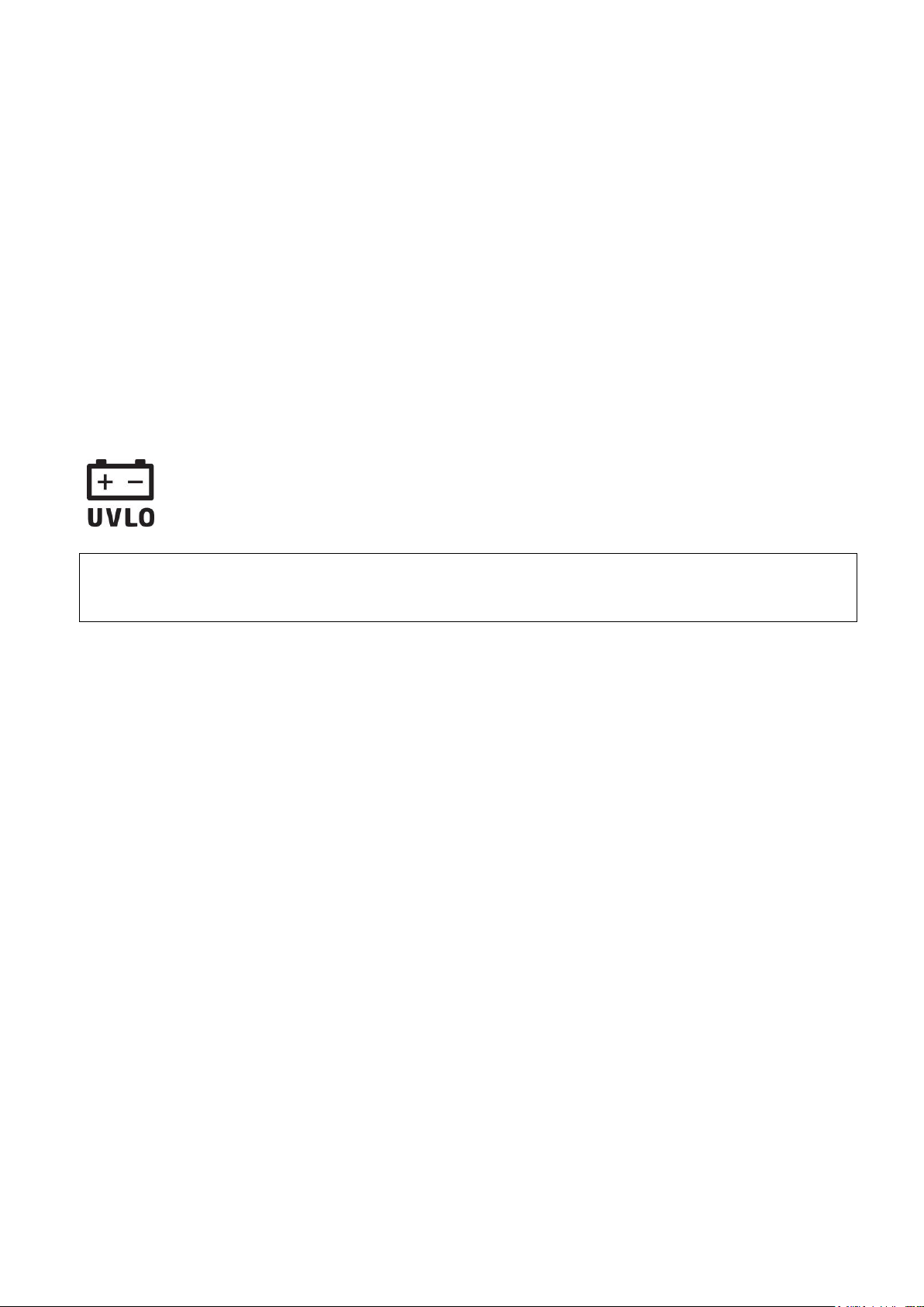
3.1 Under Voltage Lock Out (UVLO) function
The product is provided with built-in automatic power disconnection (Under
Voltage Lock Out) function. Depending on the product type, if the supply voltage
drops below 8.4…8.2V, the module turns off automatically and it turns back on
when the supply voltage is at least 11.2…11.4V.
The minimum supply voltage level required to turn the module on is 11.2…11.4V!
After turned on with supply voltage higher than 11.2…11.4V, the module can operate
stably even at lower supply voltage, but not lower than 8.4…8.2V.
If the module is powered from a power supply provided with a backup battery and there is
no other electrical load on the battery when charging fails (e.g. in case of a power cut), while
the battery discharges, the module turns off automatically at 8.4…8.2V voltage level.
Thereafter, if the battery is in good condition, it can regenerate and can reach the terminal
voltage of 11.2…11.4V where the module turns back on, then the battery may discharge
again below 8.4…8.2V. This may result a continuous switching on and off cycle that lasts
until the battery can no longer regenerate to the 11.2…11.4V voltage level. If this
phenomenon occurs, the battery is flat and it should be replaced.
Page 6

6
3.2 Input wiring
For the inputs, the normally closed or normally open dry contact should be connected
between the given input (IN1…IN4) and the negative of the power input (V-).
If a normally open activating dry contact is used, choose the NO (normally open) option at
the given input’s settings. In this case the input becomes activated and notification sending
by SMS, e-mail or call is initiated when the given input (IN1…IN4) and the V- terminal is
shorted.
If a normally closed activating dry contact is used, choose the NC (normally closed) option
at the given input’s settings. In this case the input becomes activated and notification
sending by SMS, e-mail or call is initiated when shorting between the given input (IN1…IN4)
and the V- terminal is removed.
Connecting the gate position limit switch:
When using control mode 1 or 2 with a single gate, the position limit switch of the gate
controlled by output OUT1 should be connected to input IN3. If two gates are controlled, the
position limit switch of the gate controlled by output OUT2 should be connected to input IN4.
For control modes 3, 4 and 5 the position limit switch of the gate should be connected to
input IN3.
3.3 Output wiring
Connecting the outputs should be done according to the configured control mode.
The default state of the outputs for given control modes is the following:
For control modes 1, 2, 4, 5:
OUT1: normally open dry relay contact (N.O.)
OUT2: normally open dry relay contact (N.O.)
For control mode 3:
OUT1: normally open dry relay contact (N.O.)
OUT2: normally closed dry relay contact (N.C.)
The normally open (N.O.) output provides open contact by default and closed contact upon
control. The normally closed (N.C.) output provides closed contact by default and open
contact upon control. The outputs provide dry (potential free) relay contacts.
3.4 Connections
Attention! Do NOT connect the metallic parts of the GSM antenna connector or the
module’s terminals directly or indirectly to the protective ground, because this may
damage the module!
Page 7
7
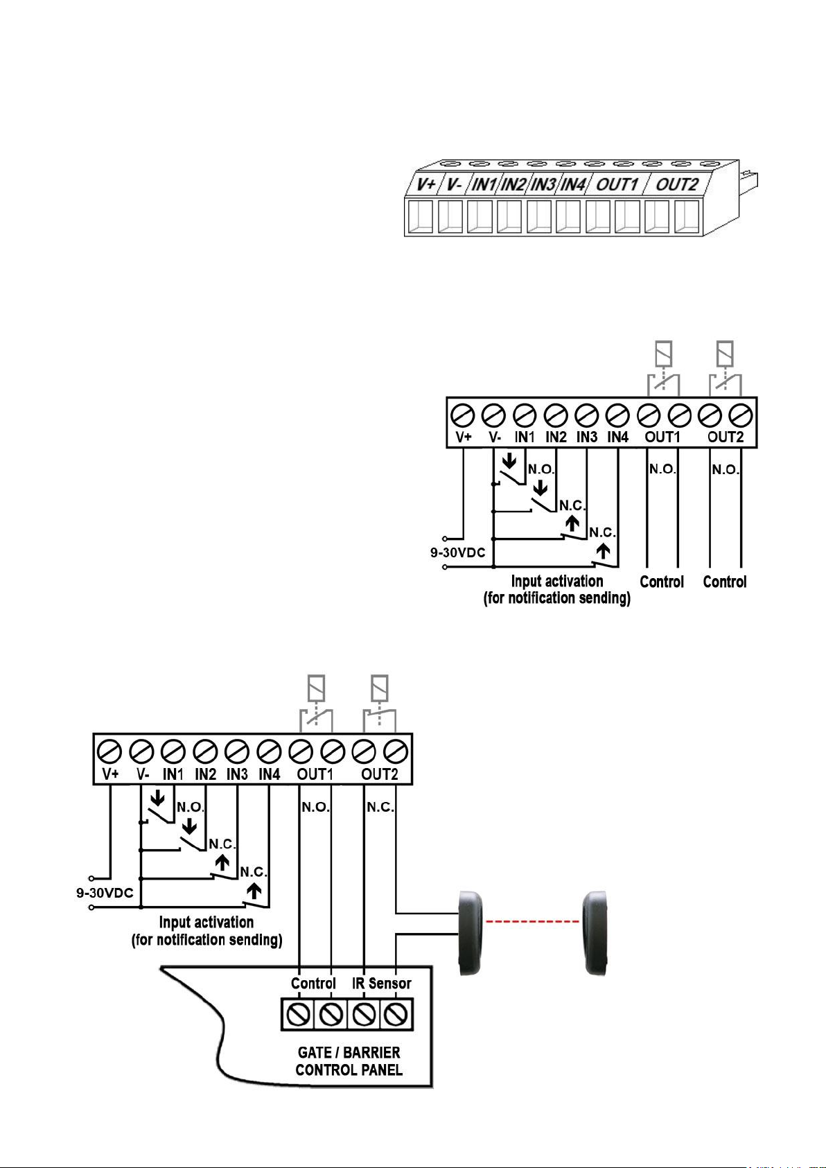
3.4.1 Wiring diagram
The example shows wiring of inputs
IN1 and IN2 when configured to
normally open, and when inputs IN3
and IN4 are configured to normally
closed.
The example shows wiring of inputs
IN1 and IN2 when configured to
normally open, and when inputs IN3
and IN4 are configured to normally
closed.
When using control mode 3, output
OUT1 is used for control while OUT2 is
used with normally closed state to
interrupt the photocell detection circuit,
thus making it possible to keep the
gate/barrier open for the configured
period of time.
System terminal inputs and outputs:
V+ Supply voltage 9-30 VAC/DC (min. 500mA)
V- Supply voltage negative (if DC)
IN1 Dry contact input 1
IN2 Dry contact input 2
IN3 Dry contact input 3
IN4 Dry contact input 4
OUT1 Relay output 1 (normally open dry contact)
OUT2 Relay output 2 (normally open dry contact)
Wiring example for control modes 1, 2, 4, and 5:
Wiring example for control mode 3:
Page 8
8
3.5 SIM card socket
The SIM card socket can be accessed by removing the cover of the aperture found on the
module enclosure. The cover can be removed by pressing it with your fingernail towards the
LED at the end where the gap is and then pulling it outwards. Insert the SIM card in the
socket. The services to be activated on the SIM card installed into the Gate Control Pro
device should be chosen according to which services of the device you wish to use. For
usage with the smartphone application and for the functions that use e-mail sending mobile
internet service is necessary. The functions that use SMS sending need SMS service and
the ones that use calls require GSM voice call service. For accessing the Internet the SIM
card should use a public APN.
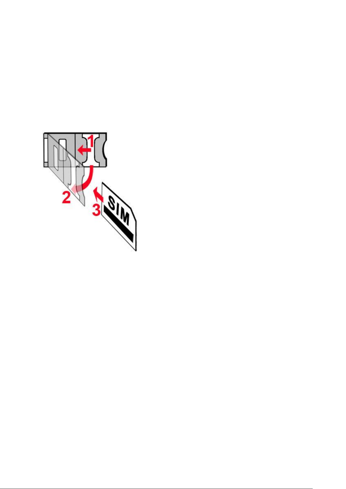
Installing the SIM card:
1. pull the metal security lock of the SIM socket
towards the LED until it clicks
2. reach under the metallic security lock with your
fingernail and pull it outwards to open the socket
3. slide the SIM card into the opened part with the
contacts facing down, as shown in the figure
Close back the opened part together with the SIM
card
Press down carefully the metallic security lock
and pull it towards the side of the enclosure until it
clicks.
3.6 Connecting the antenna
Connect the GSM antenna to the FME-M socket. The module comes with an antenna
which provides good transmission under normal reception circumstances. In case of
experiencing signal strength problems or/and wave interference (fading), use another
(directed) type of antenna or find a more suitable mounting place for the antenna.
3.7 Installation
Please check the environment before installing:
Verify the GSM signal strength with your mobile phone. It may happen that the
signal strength is not sufficient in the desired mounting place. In this case the
planned installation place can be changed before mounting the device.
Do not mount the unit in places where it could be affected by strong
electromagnetic disturbances (e.g. in the vicinity of electric motors, high voltage,
etc.).
Do not mount the unit in wet places or places with high degree of humidity.
Page 9
9
3.8 Putting into operation
Slowly flashing green
Normal operation,
connected to GSM network
Flashing red
GSM service unavailable
or system startup/restart in progress
Permanent red
SIM card error
Disable voicemail and notification in SMS about missed calls on the SIM card
installed into the module.
The module can handle the SIM card’s PIN code. If you wish to use the
PIN code management, configure the SIM card’s PIN code in the programming
software at the “Settings” section. Otherwise disable PIN code request on the
SIM card.
Enable caller identification service on the SIM card at the GSM service
provider (this service might not be enabled by default, please check). To enable this
service, install the SIM card into a mobile phone and call the customer service of the
card’s GSM service provider and enable the service in the menu, or visit one of the
service provider’s personal customer services and ask to enable this service on the
SIM card.
Check the SIM card to be installed correctly into the module.
Check the GSM antenna to be connected correctly to the module.
Check the wires to be connected as instructed in the wiring diagram.
You can power up the device (9-30 VAC/DC). Make sure that the power source is
sufficient for the operation of the Gate Control Pro module. The quiescent
current of the Gate Control Pro module is 120mA, however it may increase up to
500mA during communication and relay control. If the used power source is not
sufficient for the operation of the module, this may cause malfunctions. For such cases
230VAC/12VDC-1A power adapter can be ordered separately from the manufacturer.
3.9 LED signals
3.10 Technical specification
Supply voltage range: 9-30 VAC/DC
Nominal current consumption: 120mA
Highest current consumption: 500mA @ 12VDC, 250mA @ 24VDC
Operating temperature: -20ºC - +70ºC
Transmission frequency: GSM 900/1800 MHz
Highest load supported on outputs: 1A @ 24VAC/DC
GSM phone model: Simcom SIM800F
Dimensions: 84 x 72 x 32mm
Weight: 200g (packed: 300g)
Page 10
10
4 Configuring the Gate Control Pro module
The Gate Control Pro module can be configured in the following ways:
by computer via USB, using the programming software
by computer over the Internet, using the programming software*
by the smartphone application over the Internet (only settings regarding the user
management are available)*
You can read more about configuring by the smartphone application in the user’s
manual of the application.
*The function marked with * character are only available when a SIM card with mobile
internet access is installed in the Gate Control Pro device and the server access is
configured correctly so that the device has online connection with the server. If you wish to
use the system’s Internet-based services, it is necessary to configure in advance the
settings needed for accessing the Internet. You can learn more about these settings in the
“Internet access” and “Servers” paragraphs.
The Gate Control Pro programming software is compatible with Windows operating
systems only.
Compatibility: Windows 8.x 32/64bit, Windows 7 32/64bit, Windows XP 32/64bit.
Installing the programming software: open the software setup application and follow the
instructions of the installation wizard to complete the installation.
The latest version of the programming software can be downloaded from the manufacturer’s
website (https://tell.hu/en/products/gsm-automation/gsm-gate-control-pro).
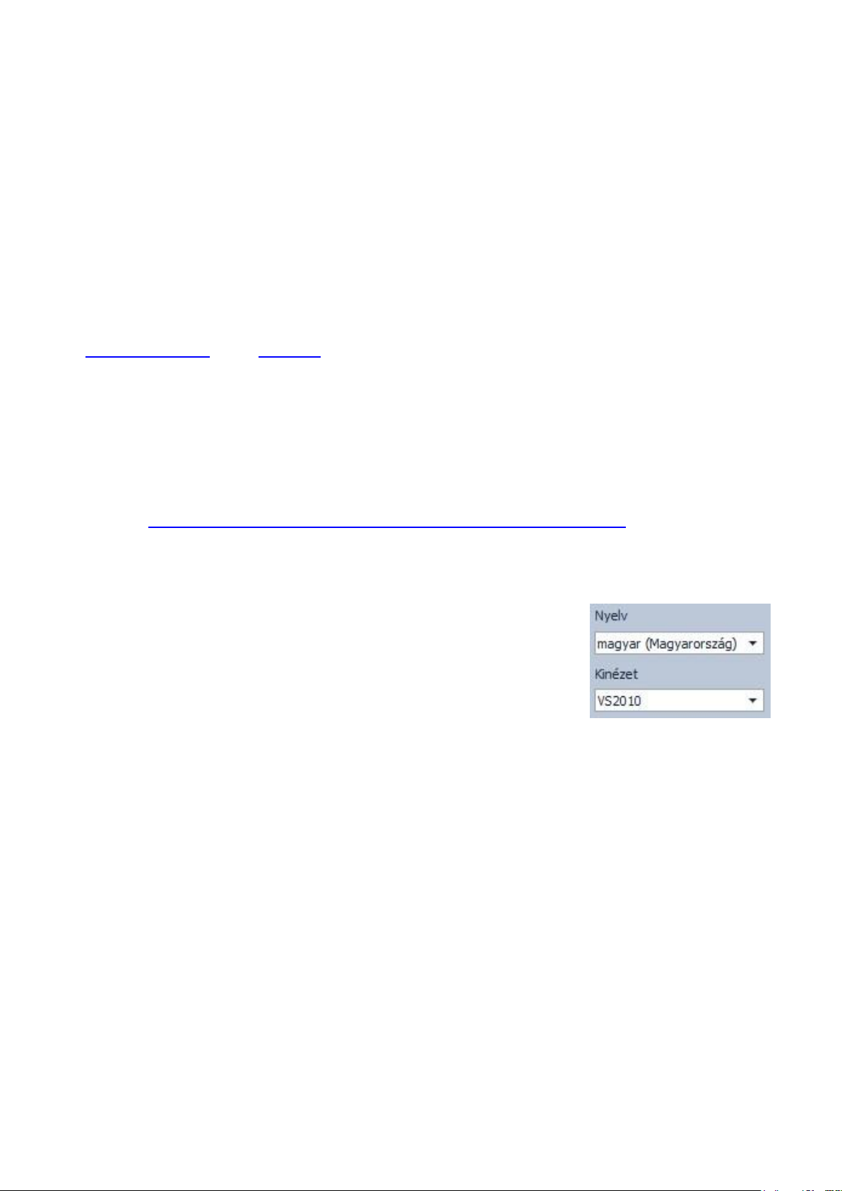
4.1 The user interface and configuration options of the software:
The user interface language can be selected from the language
selection drop-down menu placed at the bottom left part of the
program window.
The user interface skin can be changed using the “Skin”
dropdown-menu placed at the bottom left part of the program
window, where you can choose out of multiple appearance
themes.
Context-sensitive help:
On the right side of the program window a context-sensitive help can be found. If you click
on any of the settings fields within the program window, you will get brief information about
the given option or setting in the help window. The content of the help window can be
scrolled up and down using scrollbar placed on the right side of the help window. When
clicking on the “Detailed help” button, a new help window opens with more details. The size
and position of the help window can be changed as desired.
You can hide and recall the help window by clicking on the thin vertical reddish button
placed at the middle on the left side of the help window.
The software saves the changes related to appearance upon closing and applies the saved
settings when reopened.
Page 11

11
4.2 Configuring by computer via USB
To start programming the Gate Control Pro module, follow the instructions below:
Open the Gate Control Pro programming software.
Power up the Gate Control Pro module and connect it to the computer using a USB
A-B cable.
The software connects to the Gate Control Pro module using standard HID driver
which is integrated in Windows operating systems, thus there is no need to install
special USB drivers. When the Gate Control Pro module is connected to USB for the
very first time, the Windows operating system installs the drivers automatically.
The system does not use a security password for connecting via USB. After
connecting the USB cable, the software connects automatically to the Gate Control
Pro module.
Connection status is indicated by the USB status icon placed on the “Connection” tab:
: USB disconnected (grey)
: connected via USB (green)
After the connection is established, the settings can be read and changed, the event
log can be downloaded and status information is also available.
4.3 Configuring by computer over the Internet
For connecting via the Internet, the SIM card installed into the Gate Control Pro
module should have Internet service and should also use public APN.
To connect to the module via the Internet, an intermediary server is also necessary, where
both the programming software and the module connects, through which this way the
connection can be established between the programming software and the module. The
manufacturer of the product provides a server for this purpose available 24 hours a day,
which can be used free of charge.
Remote programming by computer can be done using the Gate Control Pro programming
software (desktop application). In case of remote access, the programming software
connects to the Gate Control Pro module as a client application using user name and
password, therefore it is necessary to add beforehand a new client identifier via USB
connection and assign this identifier to the user whom you wish to give remote access.
Thereby practically any user may get remote access according to its permission level.
Page 12
12
4.3.1 Adding a client identifier for the programming software
Open the Gate Control Pro programming software.
Power up the Gate Control Pro module and connect it to the computer via USB.
If you wish to assign the client identifier to a new user, add the new user in the “Users”
menu, write the changes to the module, then edit the given user’s settings again. If you
wish to add the client identifier to a user which already exists in the system, read the
user list from the module in the “Users” menu, then edit the user to which you wish to
add the client identifier.
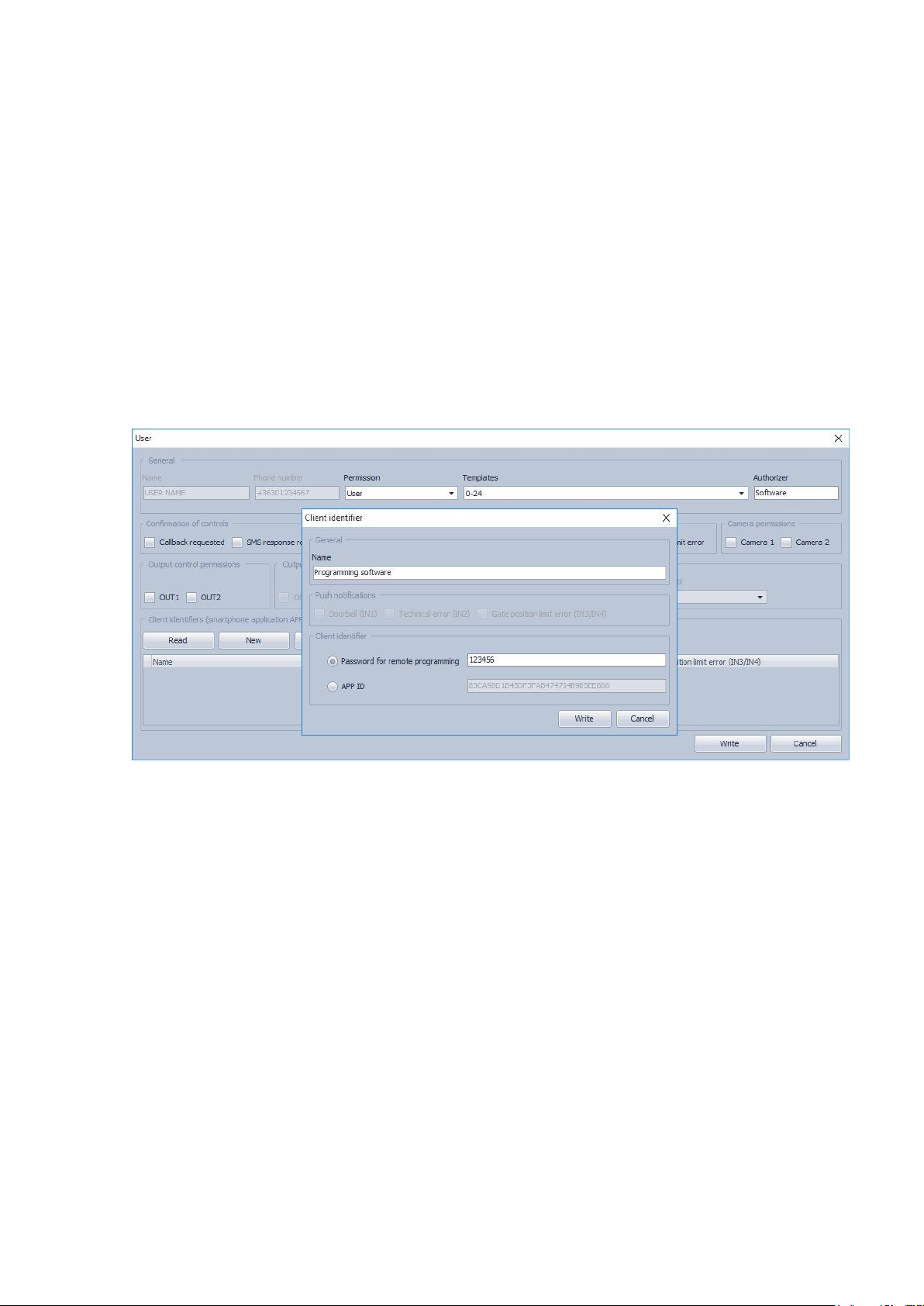
To add the new client identifier click on the “New” button in the “Client identifiers”
section of the user’s editing window. In Enter a name for the programming software in
the “Name” field of the client identifier window, then select the “Password for remote
programming” option in the “Client identifier” section and enter the new password
here. The software will ask for this password (and the user name of the given user)
when the given user wants to connect to the Gate Control Pro module for remote
programming. Click on the “Write” button to save the changes.
Thereby a client identifier and password can be assigned to any of the users, thus
providing remote access with the programming software. The user signing in remotely
via the programming software can only access the settings and options according to its
permission level.
Remote access levels:
With Super admin permission: full access, can access all settings
With Admin permission: can access everything except “Settings” and
“Customization” menus
With User permission: has no remote access permission, cannot access
anything.
The permission level can be selected in the “Permission” drop-down menu in the user
editing window.
Page 13

13
4.3.2 Managing SIM identifiers
For remote programming over the Internet it is necessary to provide the identifier (ICCID) of
the SIM card installed into the Gate Control Pro module you wish to configure. To make
remote programming of multiple Gate Control Pro devices easier, the software stores all
entered SIM identifiers and makes it possible to select a formerly used identifier from the
drop-down menu.
You can name the stored SIM identifiers at will in the SIM identifier editor window, which you
can open by clicking on the “SIM identifiers” button.
In the SIM identifier editor window you can add new SIM identifiers, delete existing ones and
change the name and identifier number of existing ones.
Adding a new SIM identifier
To add a new SIM identifier click on the “New” button, enter the desired name for the new
identifier in the “Name” field and the identifier itself in the “SIM identifier” field, then click
“OK” to store.
Changing a SIM identifier
To change an existing SIM identifier, click in the list on the identifier to be changed, then
click on the “Edit” button. Change the desired data, then click “OK” to save the changes.
Deleting a SIM identifier
To delete an existing SIM identifier, click in the list on the identifier to be deleted, then click
on the “Delete” button.
Page 14

14
4.3.3 Steps of remote programming
To start remote programming of the Gate Control Pro module, follow the instructions below:
To establish the connection, go to the programming software’s “Connection” menu,
select the Gate Control Pro module you wish to configure from the “SIM identifier”
drop-down menu, or enter the identifier of the SIM card installed into the module, enter
the server IP address (54.75.242.103), the port number (2016), your user name
registered in the Gate Control Pro module and the remote programming (client)
password assigned to your user name, then click on the “Connect” button. You
can find the SIM identifier printed onto the SIM card or you can read it from the “SIM
identifier” field of the “Module status” menu when the Gate Control Pro module is
connected via USB.
Connection status is indicated by the Internet status icon placed on the “Connection”
tab:
: disconnected (grey)
: connected via the Internet (green)
After connecting successfully, the settings can be read and changed, the event log can
be downloaded and the status information can be viewed just like when connected via
USB. Of course, data downloading and uploading takes longer over the Internet
connection than via USB.
To close the connection click on the “Disconnect” button.
4.3.4 QR code
The QR code found in the “Connection” menu is used to transfer the connection data easily
to the smart phone application. To generate a QR code, connect the Gate Control Pro
module to the computer via USB. The software reads the identifier of the SIM card installed
into the connected module automatically and prepares the QR code that includes the three
connection data (server IP address, port number and SIM identifier).
You can read the QR code with your smart device directly from the screen, or from a printed
sheet if it has been printed. To print the QR code click on the QR code using the right
mouse button, save to file or copy to clipboard, then paste into a new document (e.g. Word)
where you can also add usage information, and print from there.
Page 15

15
5 How to use the Gate Control Pro programming software
5.1 Module status
The module status menu provides information on the actual system status.
SIM identifier: the identifier of the SIM card inserted into the Gate Control Pro module
Name: the module’s type
Hardware version: the module’s hardware version
Firmware version: a module’s firmware version
System time: the system date and time
Uptime: the uptime since powered up
GSM uptime: the uptime since the last GSM network connection
IP uptime: the uptime since the last internet connection
GSM operator: the name of the GSM operator used actually
GSM signal: actual GSM signal level
Lowest GSM signal: the lowest GSM signal measured since the last GSM connection
IP address: the module’s actual IP address
Supply voltage: value of measured supply voltage in Volts
Lowest supply voltage: the lowest supply voltage value measured since powered up
Inputs (IN1…IN4): the actual status of the four contact inputs
Outputs (OUT1, OUT2): the actual status of the two relay outputs
Status messages: system status messages displayed during operation
Page 16

16
5.2 Event log
The event log includes control events and input events recorded during operation.
Available options:
: read event log from the module
: export the read event log to file in CSV format
Reading the event log from the module:
When reading the event log, you can specify by filtering options the period and event type
you wish to download. It is also possible to filter by user name, but for this first it is
necessary to download the user’s list. If no filtering option is specified, the software
downloads the entire event log.
Page 17

17
5.3 Settings
In the “Settings” menu you can configure the parameters related to the general operation of
the Gate Control Pro module.
Settings management:
The settings can be saved to file and loaded from file using the appropriate
function buttons.
Read settings from the module:
In order to apply the settings after changing, the settings should be written to the
module using the “Write” button.
Write settings to the module:
In order to apply the settings after changing, the settings should be written to the
module using the “Write” button.
Create full system backup:
You can create a full system backup after clicking on this button. The full system
backup includes all the settings, as well as users’ database, client identifiers,
templates and holidays. To create a full system backup click on the button, browse
the target folder, enter a filename and click on the “Start” button.
Restore system from backup:
To restore the system from backup, click on this button, select the backup file and
click on the “Start” button. This option is only available when connected via USB.
In case of connecting through the Internet, the connection would fail since all existing
users are erased when uploading the new data, thus the connected user too, so the user
would lock himself out of the system.
Page 18

18
System time synchronization:
The system time should be synchronized only if connecting to the server is disabled,
else the time is synchronized automatically from the server. To synchronize the time,
click on the “Time synchronization” button. The software synchronizes the time to
the PC system time, therefore please check before proceeding if the PC system time is
correct.
Send test e-mail:
This button can be used to check if the e-mail sending function works. To send a test
e-mail, click on the button, enter the e-mail address or select one from the drop-down
menu and click on the “Send” button. If the test e-mail is not received, check the
“Internet access” and “Outgoing e-mail account” settings.
5.3.1 Identification
Device name: here you can give a name to your Gate Control Pro module, which name
will also be used in the reports.
Attention! The following characters should not be used: ~ ^ < > = ’ ” , | $ &
Phone number: enter the phone number of the SIM card inserted in the Gate Control Pro
module. This is used in the smartphone application for backup GSM calls and for SMS
sending during the smart device registration process.
PIN code: if you wish to use PIN code management, enter here the PIN code of the
SIM card installed into the module. Otherwise disable PIN code request on the SIM card.
If you have configured the wrong PIN code and therefore the module is unable to connect to
the GSM network, it might happen that the SIM card reaches the PUK code request stage.
In this case install the SIM card into a cellphone, unlock it by entering the PUK code and
correct the PIN code at the module’s settings.
5.3.2 Internet access
If you wish to use the Internet-based services of the system, it is necessary to configure the
settings needed for accessing the Internet, and it is also necessary to use a SIM card with
available mobile internet service in the Gate Control Pro module.
APN: the APN name necessary to connect to the internet. (ask for this at the GSM service
provider of the SIM card inserted in the Gate Control Pro module).
User name: necessary only if the GSM service provider provides this and requires its usage
for the given APN.
Password: necessary only if the GSM service provider provides this and requires its usage
for the given APN.
Page 19

19
Online mode: The system can be configured to connect to the internet online
(continuously), or to connect only occasionally, when needed. For online connection
continuous mobile internet connection is needed, which results in larger data traffic.
If online mode is enabled, the following services will be available:
- smartphone application
- remote programming
- remote firmware update,
In turn, if online mode is enabled, the system is unable to initiate outgoing calls,
therefore the following call-based functions will be unavailable:
- notification by call upon activating an input
- callback option
If online mode is disabled, the following e-mail functions will still be available, because
they do not require continuous internet connection:
- e-mail sending upon activating an input
- e-mail reports
- test report by e-mail
5.3.3 Call durations
Incoming call duration: the time after which the system rejects the incoming calls can be
configured here in seconds. In case of entering value “0”, the system rejects the incoming
calls immediately after they are received.
Callback duration: the system is able to confirm an incoming control call by calling back the
given number. Callback option can be enabled separately for each user. With this setting it
can be configured how long the system should ring the user’s phone when calling back.
When this time expires, the system ends the call automatically. This option is not available
id “Online mode” is enabled!
5.3.4 Servers
If you wish to use the Internet-based services of the system (e-mail sending, remote
programming, remote firmware update, smartphone application), then it is necessary to
configure the availabilities of the Gate Control server(s).
The availabilities of the server provided free of charge by the manufacturer for this purpose
is the following:
Server address: 54.75.242.103
Server port: 2016
5.3.5 Test report
The system can send periodic test report by SMS and e-mail by the configured interval.
Phone number: enter the phone number to which you wish to receive test report by SMS.
E-mail address: enter the e-mail address to which you wish to receive test report. You can
enter multiple e-mail addresses separated by comma. If you wish to use the e-mailing
services of the system, it is necessary to configure the internet access and the outgoing email account settings.
Interval: the interval of test report sending specified in days.
Time of day: the time of day for test report sending.
Page 20

20
5.3.6 Outgoing e-mail account
If you wish to use the e-mailing services of the system, it is necessary to configure the
outgoing e-mail account.
SMTP service - available options:
- Default: for sending e-mails, the system uses the Gmail account provided by the
manufacturer. In this case the system sends the notification e-mails and reports from the
following e-mail address:
noreply.gatecontrol@devicemail.net
- Gmail account: here you can configure a custom Gmail account to be used by the
system to send e-mails. In this case the system sends the notification e-mails and
reports from the e-mail address of the configured Gmail account.
When you finished configuring this option, use the “Send test e-mail” button to send a
test e-mail and check if the function works.
5.3.7 Cameras
You can add to the Gate Control Pro system the availabilities of at most 2 IP cameras
which support the ONVIF standard. The system makes available the images of the
configured IP cameras in the smartphone application. Permission for viewing the images
can be configured in the editing window of the users, for each user separately and per
camera.
Camera URL: the image link of the IP camera
Camera type: the image transfer mode supported by the IP camera:
- Stream: video, continuous content
- Picture: still picture
This function works only with cameras that support the ONVIF standard!
The manufacturer does not guarantee that the Gate Control Pro can be used with any
IP camera, therefore, still before purchasing the Gate Control Pro device, the
Gate Control smartphone application assures possibility to test the camera in advance and
make sure that your camera works properly with the Gate Control smartphone application
(further details are available in the user’s guide of the smartphone application).
The list of ONVIF cameras tested by the manufacturer is available at www.tell.hu at the
Gate Control Pro product’s downloads.
There are multiple methods to obtain the camera URLs. You can use the “ONVIF Detector”
software made by the manufacturer (available on the manufacturer’s website: www.tell.hu),
the “ONVIF Device Manager” software (http://sourceforge.net/projects/onvifdm), or the
camera’s technical manual.
In order to access the camera pictures from outside your local network it is
necessary to replace the local IP address and port in the URL obtained using the
ONVIF URL detector program with the external (WAN) IP address of your router and
the external port, and after this enter the modified URL in the Gate Control Pro
programming software and write this into the module settings.
Page 21

21
Example for modification of the stream URL, if using only one camera:
Original URL:
rtsp://192.168.1.240:554/cam/realmonitor?channel=1&subtype=0&unicast=true&proto=Onvif
Modified URL in case of using static IP address:
rtsp://WAN IP:554/cam/realmonitor?channel=1&subtype=0&unicast=true&proto=Onvif
Modified URL in case of using static IP address and username/password:
rtsp://username:password@WAN IP:554/cam/realmonitor?channel=1&subtype….
Modified URL in case of using domain name:
rtsp://domain name:554/cam/realmonitor?channel=1&subtype=0&unicast=true&proto=Onvif
Modified URL in case of using domain name and username/password:
rtsp://username:password@domain name:554/cam/realmonitor?channel=1&subtype….
Further details and information on router configuration, port forwarding and dyndns
configuration you can find in the “Reference guide to the ONVIF camera support
function” document.
5.3.8 E-mail report
The system is able to send the event log and monitored events by e-mail. If you wish to use
the system’s e-mail services, it is necessary to configure the internet access and the
outgoing e-mail account settings.
Type: open the drop-down menu and select the report types which you wish to receive by email.
- Event log: a full event log can be sent daily or weekly.
- Administration: instant e-mail sending upon changing settings.
- Unauthorized opening attempt: instant e-mail sending when a user attempts
unauthorized control (out of entry period, in a restricted period, with hidden caller ID for
control modes 2…5, or if the user is unknown)
- Open-Close: instant e-mail sending upon user-initiated open-close control.
E-mail address: enter the e-mail address to where you wish to receive the reports. You can
enter multiple addresses separated by comma.
Event log sending: select the event log sending interval. The system will send the event
entries not sent yet but accumulated in the meantime, by the configured interval. There is an
exceptional case when the system does not send the event log by the configured interval.
This happens when the event storage is full. In this case the log is sent immediately when
the storage gets full. Thereafter it reverts to the normal sending interval.
Day: if you have selected weekly sending, select which day the event log should be sent.
Time of day: enter the time of day for event log sending.
Page 22

22
5.3.9 Miscellaneous settings
Installer’s e-mail address: the system sends notifications about version updates to the e-
mail address specified here. If you wish to use the e-mailing services of the system, it is
necessary to configure the internet access and the outgoing e-mail account settings.
SMS forwarding phone number: the system forwards the messages received by its SIM
card to the phone number entered here (e.g. balance information received from the GSM
service provider in case of pre-pay card). The system deletes the received message
automatically after forwarding.
SMS sending limit per day: with this setting you can limit the number of SMS messages to
be sent upon activating the inputs. The system does not allow sending more messages
within 24 hours than the number entered here. After 24 hours the counter resets
automatically, thus thereafter messages can be sent again upon activating the inputs, up to
the configured limit number. In case of entering “0” value, SMS sending will be disabled.
SMS forwarding limit per day: with this setting you can limit the number of SMS messages
to be forwarded. The system does not allow forwarding more messages within 24 hours
than the number entered here. After 24 hours the counter resets automatically, thus
thereafter incoming messages will be forwarded, up to the configured limit number. In case
of entering “0” value, SMS forwarding will be disabled, thus incoming SMS messages will
not be forwarded, but deleted.
Attention! After reaching the configured limit, but still before resetting the counter the system
deletes all incoming messages without forwarding!
Time zone: select the time zone according to the installation location. The system adjusts
the system time according to the time zone setting. If the setting is incorrect and therefore
the system times is different than the local time, this affects the operation since the access
templates, the rules and the automatic timed controls are all based on the system time.
Automated daylight saving: the system includes automatic daylight saving management
based on the configured time zone.
Push notification language: in the drop-down menu you can select the language to be
used on the assigned smart devices to display Push notification messages sent by the
system.
Date format: you can select out of two date formats:
- Hungarian format: YYYY.MM.DD hh:mm:ss
- International format: DD/MM/YYYY hh:mm:ss
First day of the week: to support international usage, the day the week starts on can be
selected.
Page 23

23
5.4 Inputs and outputs
Available options:
: read the settings from the module
: write the settings into the module
: save the settings to file
: load the settings from file
5.4.1 Inputs / Events
By activating the inputs IN1…IN4 the system can send notifications by SMS or e-mail to the
specified phone numbers or email addresses.
Input type: the input can be normally open (NO), or normally closed (NC). When set to NO,
event is generated when the input is closed, while when set to NC, opening the input
generates an event. The input is closed when the given input IN1…IN4 is shorted to „V-”
terminal (DC power negative).
Special input functions available when using the system with the smartphone application:
IN1: doorbell notification function (via Push notification)
IN2: technical error notification function (via Push notification)
IN3: gate position limit error notification (via Push notification) on the gate controlled by
output OUT1
IN4: gate position limit error notification (via Push notification) on the gate controlled by
output OUT2
You can read more about these functions in the „General operation of the GSM Gate
Control Pro / Operation of the contact inputs” chapter.
Sensitivity: input sensitivity specified in seconds. State changes of the input shorter than
the entered value are ignored by the system.
Page 24

24
Phone number: the number to which the system sends SMS and/or initiates a call upon
activating the given input. It is recommended to enter the phone number in international
format (like: +3630…).
Notification type: the way of notifying the given phone number when the input is activated.
This option is not available if “Online mode” is enabled at the internet access settings. In
this case the system can only send SMS, all call options are unavailable!
- SMS: if you choose this option, the system will send SMS only to the given phone
number, using the entered message.
- Call: if you choose this option, the system will make a call only to the given phone
number. The system does not play any sound or voice message in the call. This function
only serves to ring a phone number upon activating an input, thus the notification is free
of charge if the called party does not accept or rejects the call.
- SMS + Call: if you choose this option, the system will send SMS and will initiate a call
too to the given phone number.
Call duration: for notification by call it can be configured how long the called phone device
should ring. When the configured period of time expires, the system terminates the call
automatically, or the called party may also reject the call earlier. The notification is free of
charge if the called party does not accept or rejects the call (please also check this with your
GSM service provider because at some providers there might be differences in this service).
This option is not available if “Online mode” is enabled at the internet access settings.
E-mail address: the address to which the system sends e-mail upon activating the given
input. You can enter multiple e-mail addresses separated by comma. If you wish to use the
emailing services of the system, it is necessary to configure the internet access and the
outgoing e-mail account settings.
Message: the message to be sent by SMS and/or e-mail upon activating the given input.
Attention! The following characters should not be used: ~ ^ < > = ’ ” , | $ &
Position limit switch OUT1: enabling on input IN3 the gate position limit switch installed on
the gate controlled by output OUT1. If the gate position limit switch is connected, the module
monitors if the gate opens within the time interval configured in the “Opening timeout”
section, and if it closes within the time interval configured in the “Closing timeout” section.
If the gate fails to open or close within the configured intervals, the module sends
notifications by Push notification and/or SMS, according to the settings. The messages of
the notifications can be changed in the “Customization” menu. The system considers the
idle state of the position limit switch as the closed state of the gate. In case of NO (normally
open) wiring, the open state, while for NC (normally closed) wiring the closed state of the
position limit switch is considered as idle state.
- None: there is no position limit switch connected to input IN3
- Connected: the position limit switch is connected to input IN3
Position limit switch OUT2: enabling on input IN4 the gate position limit switch installed on
the gate controlled by output OUT2. This option is only available for control modes 1 and 2,
for connecting the second gate’s position limit switch. If the gate position limit switch is
connected, the module monitors if the gate opens within the time interval configured in the
“Opening timeout” section, and if it closes within the time interval configured in the
“Closing timeout” section. If the gate fails to open or close within the configured intervals,
the module sends notifications by Push notification and/or SMS, according to the settings.
The messages of the notifications can be changed in the “Customization” menu. In case of
NO (normally open) wiring, the open state, while for NC (normally closed) wiring the closed
state of the position limit switch is considered as idle state.
- None: there is no position limit switch connected to input IN4
- Connected: the position limit switch is connected to input IN4
Page 25

25
Opening timeout: enter the time interval in seconds, within which the gate should open,
starting from the beginning of the opening control. If the gate fails to open within the
specified interval (the position limit switch does not change state), the module sends
opening error notification by Push notification and/or SMS, according to the settings. For all
control modes, the opening timeout is counted from the beginning of the opening control
(impulses A, B, X).
Closing timeout: enter the time interval in seconds, within which the gate should close,
starting from the beginning of the opening control (or from the closing control in case of
control mode 5). If the gate fails to close within the specified interval (the position limit switch
does not change state), the module sends closing error notification by Push notification
and/or SMS, according to the settings. For control modes 1, 2, 3 and 4,
the closing timeout is counted from the beginning of the opening control (impulses A, B, X),
while for control mode 5 this is counted from the beginning of the closing control (impulse Z).
5.4.2 Control modes
The operation mode of the outputs can be configured by selecting a control mode. You can
choose out of five control modes the one which is appropriate for your application.
Control mode 1
OUT1=N.O. (normally open)
OUT2=N.O. (normally open)
A = OUT1 impulse length (seconds) => opening gate A
B = OUT2 impulse length (seconds) => opening gate B
Selective control of outputs OUT1 and OUT2, by using caller identification and by blocking
caller ID sending.
If the caller sends the caller ID, output OUT1 will be activated. If the caller blocks caller ID
sending, output OUT2 will be activated, which also allows for controlling two different gates
by call, by using this control mode.
Controlling with hidden out caller ID can be used by unlimited users (registered users
too), since this does not require user registration. You can hide the caller ID by
dialing the #31# blocking code in front of the module’s phone number (e.g.
#31#+3630….). If you wish to control both outputs, for easier handling you can add
the module’s phone number to your cellphone’s phonebook in both formats (e.g.
+3630…. and #31#+3630…).
With this control mode the two outputs can be controlled independently using the
smartphone application too.
The outputs provide opened contact by default and they become closed upon activation.
The control impulse length of output OUT1 can be configured by parameter ”A”, while the
control impulse length of output OUT2 can be configured by parameter ”B”. The values are
considered in seconds.
The gate controller panel must close the gates automatically.
Attention! With hidden caller ID anyone can control output OUT2, not only the
registered users! This option should be used for low-security applications only, since an
incoming call (with hidden caller ID) to the wrong number may also activate the output!
To increase security, do not publish the module’s phone number.
Page 26

26
Control mode 2
OUT1=N.O. (normally open)
OUT2=N.O. (normally open)
A = OUT1 impulse length (seconds) => opening gate A
B = OUT2 impulse length (seconds) => opening gate B
Selective or simultaneous control of outputs OUT1 and OUT2 using caller identification and
predefined user permissions. Permissions can be configured for each user, to control output
OUT1 only, output OUT2 only, or both outputs at the same time when calling, which also
allows for controlling two different gates by using this control mode. With this control mode
the two outputs can be controlled independently using the smartphone application
too. The outputs provide opened contact by default and they become closed upon
activation. The control impulse length of output OUT1 can be configured by parameter ”A”,
while the control impulse length of output OUT2 can be configured by parameter ”B”.
The values are considered in seconds.
The gate controller panel must close the gates automatically.
Control mode 3
OUT1=N.O. (normally open)
OUT2=N.C. (normally closed)
X = OUT1 impulse length (seconds) => gate opening
W = infrared photocell loop braking delay (seconds)
Y = OUT2 impulse length (seconds) => keeping the gate open
Z = OUT1 impulse length (seconds) => gate closing
Starting a control process using caller identification. Output OUT1 provides opened contact,
while output OUT2 provides closed contact by default. When calling, output OUT1 gives
closed contact for X seconds, then after W seconds output OUT2 gives open contact for Y
seconds, then after 1 second output OUT1 gives again closed contact for Z seconds. This
control mode can be used if the gate controller panel requires the opening and closing
control impulses on the same input (the first impulse opens the gate, the second one closes
it). The opening and closing control impulses are provided by OUT1, while inserting the
OUT2 contact in the loop of the infrared photocell, it keeps the gate open for Y seconds
(breaks the photocell loop, just like when an obstacle shows up within the photocell’s ray,
thus the gate remains open).
If the gate controller panel closes the gate automatically, there is no need for control
impulse Z. In this case 0 value should be entered for parameter Z, thus there will not be a
gate closing impulse. For some gate controller panels, if the photocell loop breaks during
gate opening, the gate stops immediately. To avoid this, a delay can be configured by
parameter W, which can be used to delay the photocell loop breaking. In such case for
parameter W enter the gate opening duration plus 2-3 seconds (e.g. if it takes 12 seconds
for the gate to open, enter 14-15 seconds for parameter W).
Keep the gate open permanently upon quick recall: if enabled, the gate remains open
permanently (Y=infinite) after receiving a second call from the same user during opening
process or opened period (during X+W+Y period). The gate will close when a third call is
received from the same user or a new call from a different user. This function cannot be
used with hidden caller ID.
Page 27

27
Control mode 4
OUT1=N.O. (normally open)
OUT2=N.O. (normally open)
X = OUT1 impulse length (seconds) => gate opening
Y = keeping the gate open (seconds)
Z = OUT2 impulse length (seconds) => gate closing
Starting a control process using caller identification. Outputs OUT1 and OUT2 provide
opened contact by default. When calling, output OUT1 gives closed contact for X seconds,
then after Y seconds output OUT2 gives closed contact for Z seconds. This control mode
can be used when the gate controller panel expects the opening and closing control
impulses on two different inputs (impulse on an input opens the gate, impulse on another
input closes the gate).
Keep the gate open permanently upon quick recall: if enabled, the gate remains open
permanently (Y=infinite) after receiving a second call from the same user during opening
process or opened period (during X+Y period). The gate will close when a third call is
received from the same user or a new call from a different user. This function cannot be
used with hidden caller ID.
Control mode 5
OUT1=N.O. (normally open)
OUT2=N.O. (normally open)
X = OUT1 impulse length (seconds) => gate opening
Z = OUT2 impulse length (seconds) => gate closing
Opening and closing by separate calls. Outputs OUT1 and OUT2 provide opened contact by
default. Output OUT1 gives closed contact for X seconds upon the first call, then upon the
second call from the same user output OUT2 gives closed contact for Z seconds. This
control mode can be used when the gate controller panel expects the opening and closing
control impulses on the same input or on two different inputs. If opening and closing control
is done on the same input, outputs OUT1 and OUT2 should be connected in parallel to the
input to be controlled. This control mode cannot be used with hidden caller ID.
Page 28

28
5.5 Customization
You can change the default name of the event log and email message elements, and some
of the available Push and SMS messages in the “Custom name” column of the
spreadsheet. If you change the names, the given elements will be shown with the custom
names in the e-mail reports and event log.
Attention! The following characters should not be used: ~ ^ < > = ’ ” , | $ &
To change the name of an element, first read the settings from the module using the
“Read” button, then double click on the element to be changed, or select it by clicking
on the element and then click on the “Edit” button. Enter the element’s custom name
in the dialog window, then click on the “Write” button.
Other options:
: export custom names to CSV format file
: import custom names from CSV format file
The manufacturer provides the default English, German and Hungarian word stock for the
customization function, which you can find in the “Localization” folder of the program
installation directory under the following filenames: “GC_Customization_EN.csv”,
“GC_Personalisierung_DE.csv” and “GC_szemelyre_szabas_HU.csv”. If you wish to
replace the actual word stock used by the module, click on the “Import” button and select
one of the mentioned language files.
Page 29

29
5.6 Admin functions
The admin functions can be used to fully erase the access templates, automatic timed
control templates, client identifiers, users and holidays, as well as to configure the global
rules.
: reading the settings from the module. To read the actual settings from the module,
click on the “Read” button.
: writing the settings into the module. After changing the settings, in order to apply the
new settings it is necessary to write them into the module using the “Write” button.
: erasing the automatic timed control templates (deletes all existing automatic timed
control templates from the system)
: erasing the access templates (deletes all existing access templates from the system)
Warning! Erasing the access templates is prohibited if there are users recorded in the
system. In this case the users should be erased first.
: erasing the users (deletes all registered users from the system)
: erasing the holidays (deletes all configured holidays from the system)
: erasing the client identifiers (deletes all existing client identifiers from the system)
Page 30

30
5.6.1 Global rule
The global rule can be used to override the entry periods defined by configured access
templates.
Type:
None: the entry permissions are considered according to the configured access templates,
holidays and user custom rules.
Allow users: access granting for control expressly for the registered users only, by ignoring
the configured access templates, holidays and user custom rules. When this option is
selected, users may control the system both by sending or blocking the caller ID (in case of
control mode 1).
Allow everyone with caller identification: global access granting for control for anyone
(unregistered users as well) by ignoring the configured access templates, holidays and user
custom rules. When this option is selected, anyone who sends the caller ID may control the
system. If the user blocks the caller ID, the request for control will be rejected, except when
controlling output OUT2 in control mode 1.
Allow everyone: global access granting for control for anyone (unregistered users as well)
by ignoring the configured access templates, holidays and user custom rules, even if caller
ID is sent or hidden, for any of the control modes.
Deny: global access restriction for control by ignoring the configured access templates,
holidays and user custom rules.
From: enter the beginning of the global rule’s validity period. You can select the date and
enter the time in the calendar after opening the drop-down menu.
Until: enter the end of the global rule’s validity period. You can select the date and enter the
time in the calendar after opening the drop-down menu.
Page 31

31
5.7 Automatic timed control
The automatic timed control function is used to control the outputs automatically at
configurable time of day. The time of control can be configured in timing templates similarly
to the access templates. This function is useful when it is needed to open the gate
automatically at certain times of day and keep it open for given periods due to e.g. higher
traffic, saving thereby the mechanics and avoiding the users to have to open the gate every
few seconds (e.g. in the morning, when a large number of people arrive at their workplace
practically at the same time). It is also possible to configure multiple automatic opening
periods for the same day by adding multiple templates.
With regard to the duration of opening and closing impulses, the automatic timed
control function always takes into consideration the time intervals configured at the
given control mode, but the operation is different at certain control modes:
in case of using control mode 1 or 2, output OUT1 and output OUT2 give permanent
closed contact during the interval between the time configured at “Open” and “Close”
options.
The automatic timed control can be used with these control modes for example with
gate controllers which keep the gate open permanently while the controlling signal
(closed contact) is present on their control input. In the “Output control” section it can
be configured which output to be controlled by the automatic timed control function
(output OUT1, OUT2 or both at the same time).
in case of using control mode 3, output OUT1 gives closed contact for X seconds at the
time configured at the “Open” option, then after W seconds (gate opening interval)
output OUT2 gives permanent open contact, thus breaking the photocell loop and
keeping the gate open till the time configured at the “Close” option, when output OUT1
gives closed contact again for Z seconds.
for control modes 4 and 5, output OUT1 gives closed contact for X seconds at the time
configured at “Open” option, then output OUT2 gives closed contact for Z seconds at the
time configured at “Close” option.
Page 32

32
If the gate’s position limit switch is connected to the module, it monitors if the gate opens
and closes at the configured times of day. If opening or closing fails, the module sends
notification about the position limit error by Push notification and/or SMS, according to the
settings, and at control modes 3, 4 and 5 it repeats the opening or closing impulse
by 1 minute, i.e. it keeps trying to open or close the gate. The opening impulse is repeated
by 1 minute until the gate opens according to the position limit switch, but up to the closing
time configured at the given timed control. The closing impulse is repeated by 1 minute until
the gate closes according to the position limit switch, but up to the next daily module restart
or power loss. The module sends the position limit error notification by SMS only once, while
if the error still persists, by Push notification it is resent upon each opening or closing
attempt, i.e. by 1 minute, but up to 3 messages only.
Available options:
: read timed control templates from the module
: add new timed control template
: edit the selected timed control template
: delete the selected timed control template
: export the timed control templates to CSV file
: import timed control templates from CSV file
Creating an automatic timed control template:
- click on the ”New” button
- enter the template’s name. The template name should not exceed 15 characters.
Attention! The following characters should not be used: ~ ^ < > = ’ ” , | $ &
- in case of using control mode 1 or 2, select which output to be controlled by the timed
control function (output OUT1, OUT2 or both at the same time)
- configure the control periods for each day of the week and holiday
- click on the “Write” button
The system allows for adding maximum 20 timed control templates.
If you wish to disable the automatic timed control of the outputs for a certain day, then enter
value 00:00 into both time fields of the given day. In the “Holiday” section you can configure
the timed control period for holidays. The holidays can be configured in the “Holidays”
menu, even for several years in advance.
Page 33

33
5.8 Access templates
The entry period can be configured by access templates. Any of the created access
templates, even more of them can be assigned separately to any user, thus the periods
(even more periods a day) can be defined for each user when they can access and control
the system. Out of the configured entry periods the system rejects the given user’s request
for control, except if this is not overridden by global rule or custom rule.
Available options:
: read access templates from the module
: add new access template
: edit the selected access template
: delete the selected access template
: export the access templates to CSV file
: import access templates from CSV file
Page 34

34
Creating an access template:
- click on the “New” button
- enter the template name. The template name should not exceed 15 characters.
Attention! The following characters should not be used: ~ ^ < > = ’ ” , | $ &
- configure the control periods for each day of the week and holiday
- click on the “Write” button
The system allows for adding maximum 50 access templates.
Control of the system is allowed within the configured entry periods, and is denied out of the
periods. If you wish to prohibit entry for a certain day, then enter value 00:00 into both time
fields of the given day. In the “Holiday” section you can configure the entry period for
holidays. The holidays can be configured in the “Holidays” menu, even for several years in
advance.
5.9 Users
Control of the system can be done from the registered user phone numbers and smartphone
applications, unless the global rule is configured otherwise. Depending on the variant of your
device, you can register up to 20 or 1000 users.
Page 35

35
Available options:
: read users from the module
: add new user
: edit the selected user
: delete the selected user
: export the users to CSV file
: import users from CSV file
To add a user click on the “New” button, enter the required data and configure the
settings, then click on the “Write” button.
User settings:
Name: the user name should not exceed 40 characters. The user name is case sensitive.
Attention! The following characters should not be used: ~ ^ < > = ’ ” , | $ &
Phone number: it is recommended to enter the phone number in international format (e.g.
+3630….). The system accepts maximum 20 digits. Accepted characters are “+”, “0…9”
only.
Permission: you can choose out of three permission levels:
- User: can only control the system
- Admin: can control the system and manage users (add/modify/delete)
- Super admin: full permission, can control the system and manage users, settings,
templates and holidays
Access templates: any of the added access templates, even multiple templates can be
assigned to a user. If there is no access template assigned to the user, then a 0-24 hour
template will be assigned automatically, which means that the given user can control the
system at anytime, 24 hours a day. To assign access templates, enable the checkboxes of
the given templates in the drop-down menu.
Page 36

36
Authorizer: here the identifier of the admin or super admin is shown, who has registered the
new user. This is filled in automatically by the system. If the new user has been added using
the programming software, then “Software” will be shown here.
Callback requested: the system is able to confirm a successful control call by callback.
Callback request can be enabled for each user separately. This function is not available
when “Online mode” is enabled at the internet access settings.
SMS response requested: the system is able to confirm a successful control by SMS.
Confirmation of controls in SMS can be enabled for each user separately.
Push notification permissions:
Doorbell: enables or disables the doorbell function assigned by factory default to input
IN1, globally for all smart devices of the given user. If this option is enabled, then those
smart devices for which the “Doorbell (IN1)” option is also enabled in the “Client
identifier” window, will receive ringing notifications by Push notification when input IN1
is activated. If this option is disabled, then the smart devices of the given user will not
receive ringing notifications.
Technical error: enables or disables the error notification function assigned by factory
default to input IN2, globally for all smart devices of the given user. If this option is
enabled, then those smart devices for which the “Technical error (IN1)” option is also
enabled in the “Client identifier” window, will receive “Technical or device error”
messages by Push notification when input IN2 is activated. If this option is disabled,
then the smart devices of the given user will not receive technical error notifications.
Gate position limit error: enables or disables the position limit error notification
function assigned by factory default to inputs IN3 and IN4, globally for all smart devices
of the given user. If this option is enabled, then those smart devices for which the
“Gate position limit error (IN3/IN4)” option is also enabled in the “Client identifier”
window, will receive messages by Push notification if the gate fails to open or close
within the configured time intervals. If this option is disabled, then the smart devices of
the given user will not receive gate position limit error notifications. If a gate position limit
error occurs, the module sends the error notification by Push notification to all users for
which this option is enabled.
SMS notifications:
Gate position limit error: enables or disables position limit error notification sending by
SMS to the given user’s phone number, function assigned by factory default to inputs
IN3 and IN4. If this option is enabled, the module sends notification by SMS if the gate
fails to open or close within the configured time intervals. If a gate position limit error
occurs, the module sends the error notification by SMS to all users for which this option
is enabled.
Camera 1, Camera 2: enables access to the IP cameras. If this option is enabled, access to
the pictures of the cameras will be available in the smartphone applications of the given
user, according to the settings.
Page 37

37
Output control permissions:
OUT1, OUT2: enable/disable permission for selective control of outputs in the
smartphone applications of the given user. It can be configured for each user
separately, which output to be controllable from the smartphone applications (output
OUT1, OUT2 or both). This option is only available in control modes 1 and 2.
Output control by call:
OUT1, OUT2: enable/disable selective control of outputs by call. It can be configured for
each user separately, which output to be controlled by call, using caller identification:
output OUT1, OUT2 or both at the same time. This setting also refers to controls
initiated using the smartphone application by backup phone call, when controlling over
the Internet fails due to a connection error. Unfortunately from a call it cannot be
determined which output the user would like to control, therefore it should be configured
at this option in advance, which output (or both at the same time) to be controlled by call
in such case. This option is only available in control modes 1 and 2.
Custom rule: the access templates assigned to the user can be overridden by the custom
rule. This function is useful when the entry permission of the given user has to be different in
some manner from the access templates (e.g. at a company any user may control the
system on a certain day except this user, because of being on holiday, etc., or even on a
weekend day, entry is prohibited for all users, except this user who has to work).
Custom rules are only overridden by the global rule, which can be configured in the
“Admin functions” menu.
Custom rule settings:
Type:
- None: no custom rule configured
- Allow: can control the system in the specified period against the prohibition by access
templates
- Deny: control of the system is denied in the specified period against the permission by
the access templates
Authorizer: here the identifier of the admin or super admin is shown, who has configured
the custom rule for the given user. This is filled in automatically by the system. If the
custom rule has been configured using the programming software, then “Software” will
be shown here.
From: enter the beginning of the custom rule validity period. You can select the date and
enter the time in the calendar after opening the drop-down menu.
Until: enter the end of the custom rule validity period. You can select the date and enter
the time in the calendar after opening the drop-down menu.
Client identifiers
Here you can add and manage identifiers of client devices and applications connecting to
the Gate Control Pro module (smart devices, remote access over the internet for the
programming software).
The maximum number of client identifiers supported is 2000, which can be distributed
arbitrarily between the registered uses. These may be smartphones, tablets etc., on which
the Gate Control smartphone application has been installed, or the programming software
for remote access). The smart devices assigned to given user automatically inherit the
permissions and settings of the given user.
Page 38

38
The client identifiers are automatically registered in the system upon the approval by the
administrator of the assignment requests sent by users through the smartphone application.
The client identifier is registered to the username specified by the user who sends the
assignment request.
In the “Client identifiers” section you can read and delete the client identifiers, enable or
disable the doorbell, technical error and gate position limit error notifications separately for
each identifier, as well as add new identifiers manually. Adding identifiers manually may be
needed if e.g. an identifier has been deleted and you wish to add it again without having to
send the assignment request again from the smartphone application, or if you wish to send
the assignment request from the smartphone application via the Internet (e.g. if the given
smart device is not equipped with a phone, thereby the request cannot be sent by SMS)
when registering the very first (admin) user. In the latter case, first it is necessary to add the
user and assign Admin or Super admin permission, then add the client identifier to this
user.
To add a new client identifier manually, click the one “New” button, enter the name of the
smart device in the “Name” section of the “Client identifiers” window, select the “APP ID”
option and paste here the application identifier found in the “APP ID” section of the
Settings/About menu or at the bottom of the “Assigning over the Internet” page in the
smartphone application, then click on the “Write” button. The smartphone application allows
you to copy and paste the identifier into an e-mail or Skype or other application to send it
over to the PC, where you can copy it again an paste into the “APP ID” field, thus it is not
necessary to type in the long code.
Doorbell (IN1): if this option is enabled, the system sends ringing notification by Push
notification to the given smart device upon activating input IN1.
Technical error (IN2): if this option is enabled, the system sends “Technical or device
error” message by Push notification to the given smart device upon activating input IN2.
Gate position limit error (IN3/IN4): if this option is enabled, the system sends notification
by Push notification to the given smart device if the gate fails to open or close within the
configured time intervals.
Page 39

39
5.10 Holidays
You can select the holidays even for multiple years in advance by double clicking on the
dates in the calendar. The selected dates will be highlighted with red background color. To
unselect a date, double click again on it. For the selected holidays entry will be permitted
within the period configured in the “Holiday” section of the access templates, and will be
prohibited out of the period. The entry permission can be overridden with custom or global
rules.
For the automatic timed control templates it can be configured in the template’s “Holiday”
section, in what period shall the system control the outputs automatically on the predefined
holidays.
Available options:
: read holidays from the module
: write holidays into the module
: export holidays to CSV file
: import holidays from CSV file
Page 40

40
6 Replacing the SIM card
If the “Online mode” is enabled in the settings, the Gate Control Pro module is identified in
the system by the identification number of the SIM installed into the module, therefore
replacing the SIM card affects the operation of the system. If it is necessary to replace the
SIM card for any reason, please follow the instructions below:
Power down the module, replace the SIM card and power up the module.
If the module’s phone number has also changed by replacing the SIM card, update
the phone number in the settings.
After replacing the SIM card it is necessary to delete the given module’s control
button in all smartphone applications assigned, and the control button should be
added again by assigning the smartphone applications again to the Gate Control
Pro module.
If the “Online mode” is disabled and the module is not used with the smartphone
application, to replace the SIM card just power down the module, replace the SIM card and
power up the module again.
7 Contents of the package
GSM Gate Control Pro + system terminal
GSM 900/1800 MHz antenna
Installation and application manual
Smartphone application user’s manual
Smartphone application quick start guide
Warranty card
 Loading...