

Page 1
EcoWave Featuring the EcoTouch
Installation, Operation & Maintenance Guide
Page 2

Table of Contents
Table of Contents ............................................................................................................... i
Introduction...................................................................................................................... 1
Conventions Used in this G uide............................................................................................. 1
T he EcoSmart Energy Management System ............................................................................... 2
Regulat ory Compliance ...................................................................................................... 2
Overview: EcoWave Remote Thermostat/Controller Package.......................................................... 3
EcoSource ........................................................................................................................ 5
Wiring .......................................................................................................................... 5
High/Low Volta ge Options .................................................................................................. 6
High Voltage Installation .................................................................................................... 6
Low Voltage Installatio n ................................................................................................... 14
Instructions Common to All Three Low Voltage Opti ons .............................................................. 21
EcoTouch ....................................................................................................................... 24
EcoTouch Location Planning .............................................................................................. 24
Installation .................................................................................................................. 26
Eco Touch Guest Screen Controls & U ser Interface..................................................................... 29
Device Association ............................................................................................................ 31
Pair EcoTouch with EcoSource............................................................................................ 31
EcoTouch Configuration Changes ........................................................................................... 32
Change Channel ............................................................................................................ 32
Unpa ir Eco T ou ch ............................................................................................................ 32
Activate “Display Mode” Opt ion .......................................................................................... 32
S ystem Status Screen ...................................................................................................... 32
Regular Maintenance ......................................................................................................... 33
Troubleshooting ............................................................................................................... 34
Troubleshooting ............................................................................................................... 35
Troubleshooting ............................................................................................................... 36
Index ......................................................................................................................... 37
Appendix A .................................................................................................................. 39
EcoWave Fea t ur i ng EcoTouch IO&M Guide Telkone t, Inc.
For Use with Firmware Version 2.x 20800 Swenson Drive, S uite 175
Table of Contents Waukesha, WI 53186
Revision 2 (800) 380-9640
Page i www.telkonet.com
Page 3

Com pany Headquarters :
Cus to mer S uppo rt:
EcoSmart Sales:
Telkonet, Inc.
(800) 380-9640
(888) 703-9398
20800 Swenson Drive
Email:
Email
Suite 175
ecosmartsupport@telkonet.com
sales@telkonet.com
Waukesha, W I 53186
P (414) 223-0473
F (414) 258-8307
EcoWave Fea t ur i ng EcoTouch IO&M Guide Telkone t, Inc.
For Use with Firmware Version 2.x 20800 Swen son Dr ive, Suite 175
Table of Contents Waukesha, WI 53186
Revision 2 (800) 380-9640
Page ii www.telkonet.com
Page 4
amet.
Fusce pharetra risus eu
nibh consequat vol utpat.
elit dignissi m feugiat.
Introduction
Conventions Used in this Guide
This is an informational tip, used to convey
relevant but not necessaril y urgent
information.
This is a warning, used to convey im porta nt
information.
This is a strong warn ing, used to convey
urgent and often safety -rel ated inform ation.
Chapt er Names
Main chapters in this manual wil l have headings in l arge green
font as shown ab ove. Main chapter nam es al so appe ar in the
footer.
Sub-Chapter Names
Within the m ain chapters wil l be rel evant sub-chapter s, which
are presented with bold, bl ack headings as shown above.
Footers
Footers conta in the docum ent name, chapter nam e, docum ent
version numb er and page numb er, as show n here:
Procedure: Steps Described Here
Procedura l S teps are indicated as such in the heading, which
begins with the word, “Procedure:” a s show n a bove . T he step s
are outl ined as shown in the foll owing exam pl e:
Step 1 Navigate to the Config Menu > Al ert Setup.
Step 2 Click the Add New Alert Trigger button in
the top l eft corner of the Al ert Setup Screen.
Step 3 Enter a descriptive A lert Name.
Int roducing a N ew Scr een
When a screen is introdu ced, a screen print is provided. Bel ow
the screen print will be its l ocation and an expl anation of the
screen’s inten ded purpose as shown in this exam pl e:
Screen and Tab Nam es
Screen and Tab names are underl ined, as shown in this exam pl e:
The Th ermosta t Sta t us Screen shows al l rooms and
their status i nform atio n at a glan ce.
F iel d N am es
Field names appear in bol d font; field explanations appear next
to the fiel d name as shown i n this exam pl e:
Device Sel ect the device type.
Position The order in which attached devices are
associated.
MAC Address MAC address of the attached device.
Field Selection Choices
Field selection choices are in ital ics as shown in this exam pl e:
Select the Alerting Dev ice Type from the dropdown
m enu. Choices are: All Thermostats, All Pipe Sensors,
Sin gle Devi ce and Outdoor Temperature.
The “>” Symbol
The ">" symbol is used to describe a m enu choice and com m and
selection. For exampl e:
Configuration Menu > Al ert Setup m eans cl ick on the
Configuration Menu, then cl ick on Al ert Setup.
Tables
Tables provide visual presentations of related data such as
hardw are components and expl anations as shown in this
example:
Pin Label on Backplat e Function
1
iaculis
2
velit
3
sagittis
Lorem ipsum dolor sit
Uisque laoreet augue eu
Troubleshooting
Assistance with troubl eshooting begins with the red header as
shown above.
EcoWave Fea t ur i ng EcoTouch IO&M Guide Telkone t, Inc.
For Use with Firmware Version 2.x 20800 Swenson Drive, S uite 175
Introduction Waukes ha , WI 53186
Revision 2 (800) 380-9640
Page 1 www.telkonet.com
Page 5

EcoWave Package Overview
The EcoSmar t Ener gy Manag ement Sys tem
The EcoSma rt Energy M anag ement S ystem reduces H VAC energy consumption without i nterfering with occupant
comfort.
EcoSmart thermostats such as the EcoTouch automatically learn and adapt to the heating and cooling patterns
of each room. For example, a room on the eas t side of a building will receive direct sunlight in the morning and
will either need less HVAC heating or more H VAC cooling. However, as the day progres s es, the room will need
more HVAC heating or less HVAC cooling as it moves into the s hade. An EcoS ma rt thermos tat will continu ally
monito r the room, learn its patterns, a nd adjus t its heati ng and cooling prof iles according ly.
EcoSm art thermos tats also learn and a dapt to occupant s chedules . W hen a room is unoccupied, the EcoTouch
will enter an energ y s av i ng m ode, allowing the r oom to drift a way from the desir ed set point. D uring this drift
period, the thermos tat will operate the HVAC unit less often, reducing energ y costs . When the room becomes
occupied again, the RecoveryTime™ technology built into each EcoTouch will retu rn the room to the s et point
without occupant interaction.
The EcoWave is available i n several configurations to address specific requirements of multiple appli cations
including hotel, classroom, office, university dormitory, military resi dence hall, reta il, public a rea, convention
center, and a wide v ariety of commercial and industrial spaces.
The firmware of standalone EcoWa ve thermostats is identical to the firmware of netwo rked versions.
Sta ndalone T hermos tats can be networked by adding a network module to the base units at any time.
Progra mming features us ed during installation, maintenance, and troubleshooting are available in the onscreen M ai ntenance Menu.
Regulatory Compliance
FCC ID: XV6SS6560
This device complies with Part 15 of the FCC Rules. O perati on is s ubject to the following two conditions : (1)
this devi ce may not cause ha rmful i nterference, and (2 ) this dev ice mus t accept any interference receiv ed,
including interfere nce that m ay cause undes ired opera tion.
This equipment has been tested and found to comply with the limits for a class B di gi tal device pursua nt to
part 15 of the FCC Rules. These limits are designed to provide reasonable protection against harm ful
interference in a residential installation. This equipment gener ates , us es a nd can radiate ra dio frequency
energy and i f not installed and us ed in accordance with the ins tructions , may cause har mful interference to
radio comm unications . However, there is no guarantee that i nterference will not occur in a particular
installation. If the equipm e nt does cause harmful interference to r adio or television reception, which can be
determined by turning the equipment off and on, the user is encouraged to try to correct the i nterference by
one or m ore of the following m easures:
• Reori ent or relocate the receiv ing antenna.
• Increas e the s eparation between the equipment and the receiv er.
• Connect the equipment into a n outlet on a circuit differe nt f rom that to which the receiv er is
connected.
• Cons ult the dealer or ex perienced radio/TV technician for help.
EcoWave Fea t ur i ng EcoTouch IO&M Guide Telkone t, Inc.
For Use with Firmware Version 2.x 20800 Swenson Drive, S uite 175
Waukesha, WI 53186
Revision 2 (800) 380-9640
Page 2 www.telkonet.com
Page 6
EcoWave Package Overview
In order to maintain compliance with FCC regulations , shielded cables must be used with this equipment.
Operati on with non-approved equipment is likely to result in interference to radi o and TV reception. T he us er
is cautioned that chang es a nd modifi cations made to the equipment without the approv al of the m anufa cturer
could void the user’s authority to operate the equipment.
To satisfy RF exposure r equirements, this device and its antennas must opera te with a separation distance of a t
least 20 cm from all persons and must not be co-located or operating in conjunction with any other antenna or
transmitter.
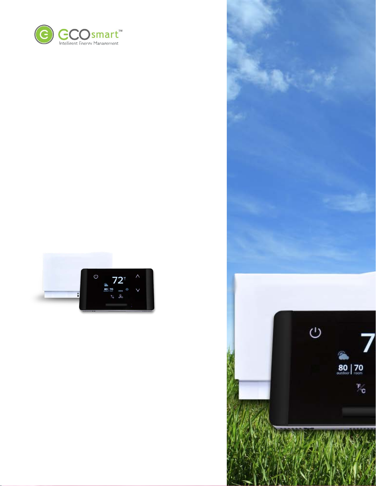
Overview: EcoWave Remote Thermostat/Controller Package
The EcoWave package is compris ed o f two hardware components as s hown below. T ogether they form a
wireless progra mmable controllable thermostat. It can be easily installed on packaged terminal air
conditioners, fan coils, heat pumps, split systems, and more. With software-bas ed relay control and fan s peed
config uration, progra mmi ng s etup is s imple and fas t.
• Dis play unit
• Place in optimum location for tempera ture measurement and
EcoTouch
EcoSource
ease of occupant use
• HVAC Controller
• Install in or on HVAC unit
• Accepts a s so ciatio n with 15 total compatible wireless dev ices
• Each compatible wireless devi ce can be ass ociated to
multiple EcoSources
Accomodates a Variety of Configurations
EcoWave Fea t ur i ng EcoTouch IO&M Guide Telkone t, Inc.
For Use with Firmware Version 2.x 20800 Swenson Drive, S uite 175
Waukesha, WI 53186
Revision 2 (800) 380-9640
Page 3 www.telkonet.com
Page 7

EcoWave Package Overview
The EcoWav e Package can be config ured for many different H VAC
scenarios. For example:
One EcoTouch can contr ol m ultiple H VAC s yste ms , e ach equi pped
with an EcoSource, but all di rected by a s ing le EcoTouch display
unit. T his type of ins tallation reduces the complexity of running
multiple H VAC units in a sing le large s pace and eliminati ng the
potential of oppos ing modes forcing equipment to compete
against each other.
Multiple EcoTouches can control one HVAC system, equipped
with one EcoSour ce.
The wiring interf ace conforms to industry s tandards . Telkonet
can develop specific wiring diagrams, if a complete s pecification
is provided for the HVAC unit(s) in use at the site.
EcoWave Fea t ur i ng EcoTouch IO&M Guide Telkone t, Inc.
For Use with Firmware Version 2.x 20800 Swenson Drive, S uite 175
Waukesha, WI 53186
Revision 2 (800) 380-9640
Page 4 www.telkonet.com
Page 8
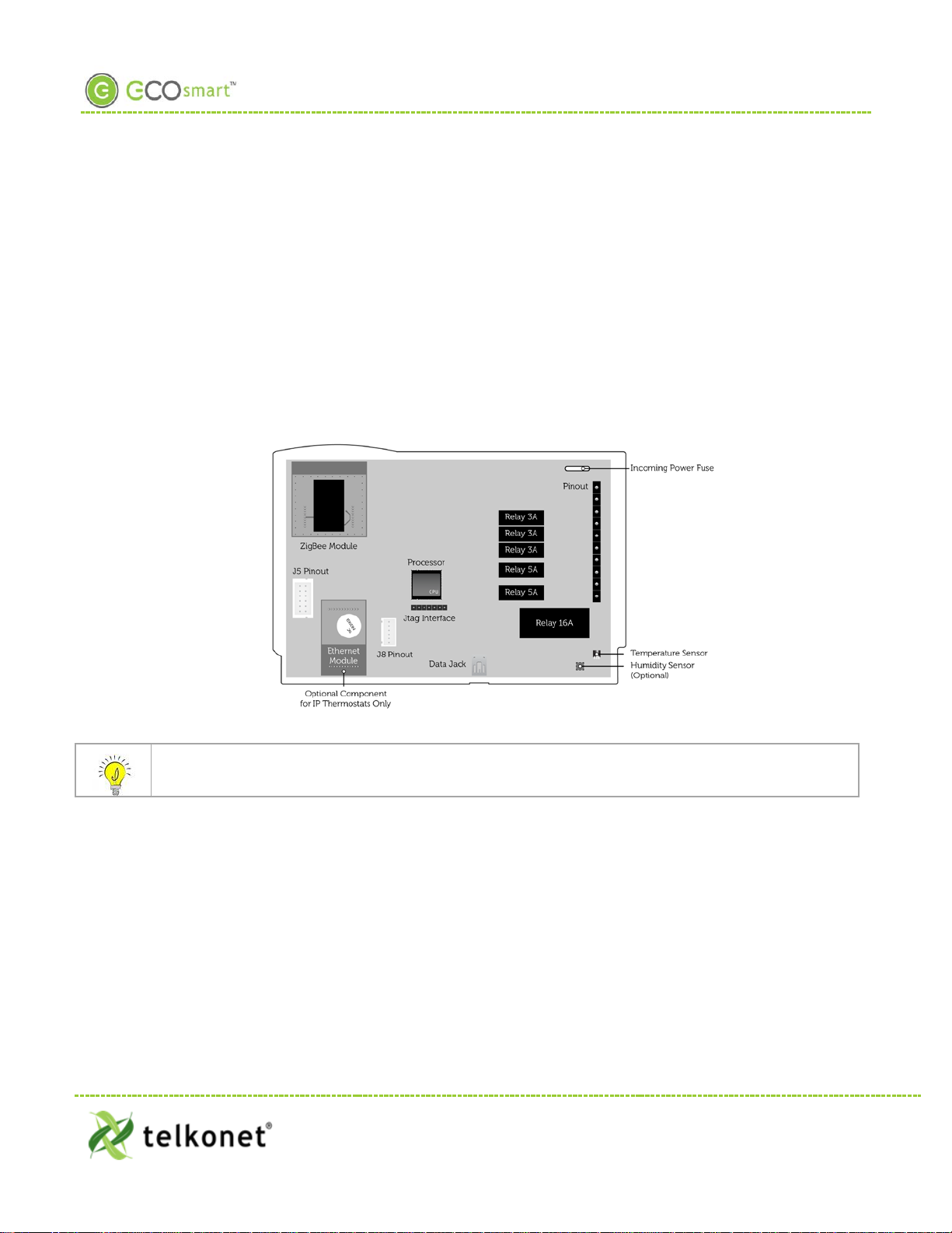
EcoSource Installation
EcoSource
Wiring
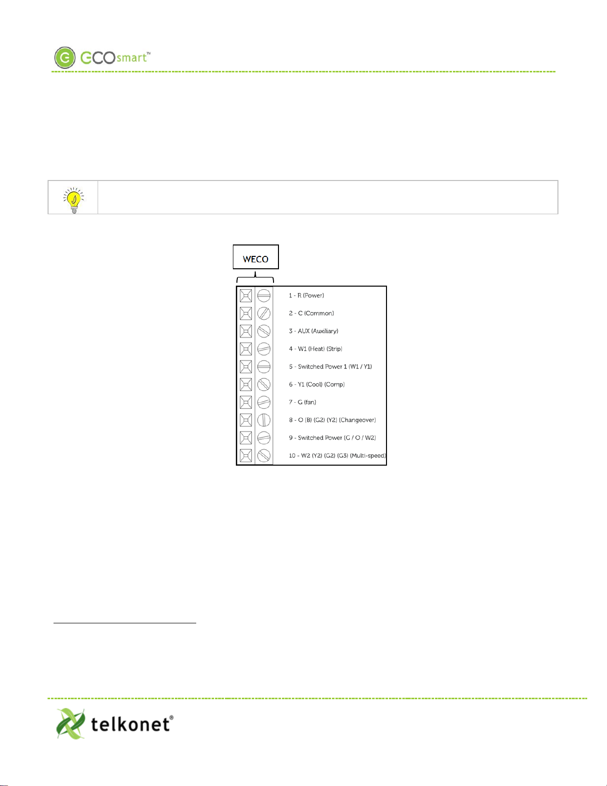
The EcoSource controller connects to the HVAC s ys tem via s tanda rd wiring conv entions , us ing 12-277VAC
voltages supplied by the HVAC equipment. T he EcoSource can accept three dif ferent power sources, which
as si s t in s cenarios where di fferent components (heat, fan) are powered by different v oltages . T his
simplifies installation on units such as fan coils.
The EcoSo urce a ccepts s tandard the rmos tat wiri ng, typically 14-22 AWG. Wiring conventions follow
indus try standa rds; however, i t is importa nt to note that the rela y confi gura tion is dynami c and can be
modi fied at the factory or in th e field.
Figure 1: Internal View EcoSourc e
If the EcoSource will be mounted inside a metal HBSC unit or in a room with a large amount of metallic
equipment that may cause RF interference, an external antenna may be necessary.
EcoWave Fea t ur i ng EcoTouch IO&M Guide Telkone t, Inc.
For Use with Firmware Version 2.x 20800 Swenson Drive, S uite 175
EcoSource Waukesha, WI 53186
Revision 2 (800) 380-9640
Page 5 www.telkonet.com
Page 9

EcoSource Installation
High/Low Voltage Options
High Vo l tage Install atio n Optio n (page 6)
• High Voltage is defined as 48 volt o r
greater.
• There a re t wo i ns ta llatio n options:
1) JBOX with Vertical Mud Ring Mount:
requi res ada pter plate a s sh own in
Figure 2.
2) Factory HVAC Mount
Low Voltage Installation Options (page 14)
• There are 3 optio ns; select based on code
and des i red look :
1) Drywall mount: no conduit required;
no JBOX a dapter plate requi red.
2) JBOX with Vertical Mud Ring Mount:
requi res ada pter plate a s sh own in
Figure 2.
3) JBOX with Horizontal M ud Ring
Mount: requi res wing nut, hole mus t
be dri lled in backplate ; no JBO X
plate required.
High Voltage Installation
(Fo r Low Voltage Installation instruction s, se e page 14).
Mounting Preparation
The back plate type must be defined as low or high voltage prior to shipment.
EcoWave Fea t ur i ng EcoTouch IO&M Guide Telkone t, Inc.
For Use with Firmware Version 2.x 20800 Swenson Drive, S uite 175
EcoSource Waukesha, WI 53186
Revision 2 (800) 380-9640
Page 6 www.telkonet.com
Page 10
• Level
EcoSource High Voltage Installation
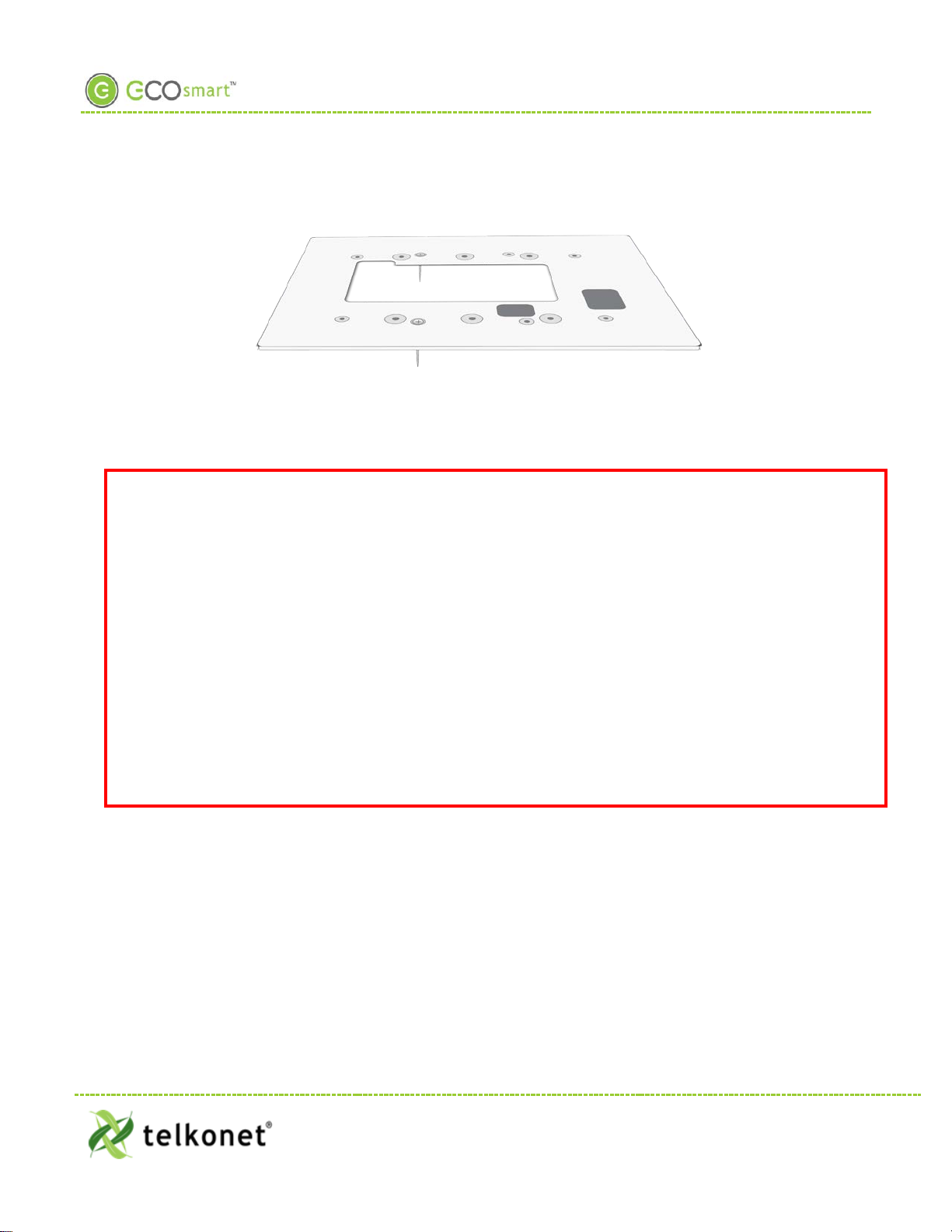
Figure 2: Telkonet JBOX Adapter Plate
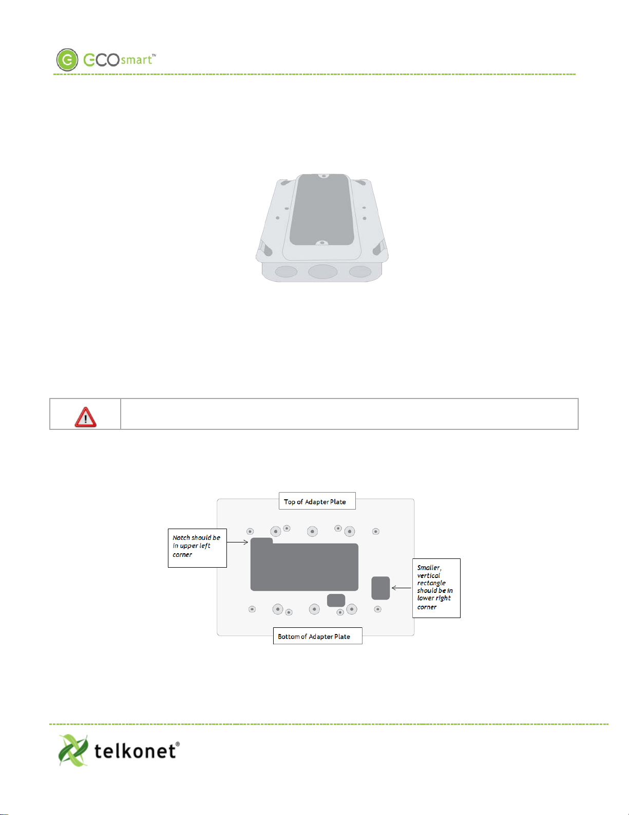
For all high voltage installations a s ingle gang mud ri ng mus t be mounted VERTICALLY on a JBOX. A Telkonet
JBOX A dapter Plate (see Figure 2) i s re qui red f or a ll JBO X i ns ta llatio ns .
• W eco t er min a l on -site wiring for high voltage installation is not allowed. You must use the pr e-
shipped 16-gu age wired backplate provided by Telkonet.
• Hi gh voltag e i ns tal la tion s hou ld on ly be per for med by a qualified heating & air conditioning
contr actor or licensed electrician.
• Failure to understand and follow all instructions carefully b efore installing or operating this
d evice could cause personal injury and/ o r property damage.
• All wiring must c onf orm to loc al an d na tion al elec tr ic al ord i na nc es and cod es.
• Prevent electr ical shock, personal injury, and equipment damage: prior to installation or
service, disconnect sys tem’s elect ric power at ma in fuse or circuit brea ker box.
EcoSource Hi gh V ol tage Requi r ed Equipm ent
• EcoSource (P/N: SS6500)
• EcoTouch (P/N: SS 6560)
• High Voltage Backplate
• Telkonet High Voltage JBOX Adapter
• T wo # 6 -32 1” screws
• Four #5 ½” coarse thread s crews
• Voltmeter
CAUTION!
• Phillips screwdriv er
• UL rated insulating tape
• Wire stripper
• Wire cutter
• Wire nuts
EcoWave Fea t ur i ng EcoTouch IO&M Guide Telkone t, Inc.
For Use with Firmware Version 2.x 20800 Swenson Drive, S uite 175
EcoSource Waukesha, WI 53186
Revision 2 (800) 380-9640
Page 7 www.telkonet.com
Page 11
EcoSource High Voltage Installation
Installation Steps
Step 1 Ensure the JBOX has been installed with a vertical s ing le gang mud ring. See Figure 3.
Figure 3: Vertical Single Gang Mud Ring
Step 2 Turn off power at E coSource or mounting lo cation us ing a disconnect switch or brea ker
lockout/ tag out o n appro pria te bre ak er pane l.
Step 3 Test that power is off by using a voltmeter.
Step 4 Strip the LINE wire ba ck 0.25 inches .
Step 5 Cap the LINE wire with a wire nut or electrical tape.
Step 6 Cut the COMM O N wire s o the copper is flush with the ins ulation.
Step 7 Stri p all wires ex cept for COM M ON back 0. 25 inches.
Reminder: For all high voltage installations, a single gang mud ring must be mounted
VERTICALLY.
Step 8 Determine which end of the adapter plate s hould be ins talled a s the top, and which end s hould
be installed as the bottom. As shown i n Figure 4, the notch in the main display should be in the
upper left corner, and the smaller, vertical rectangle should be in the lower right corner.
Figure 4: Determine Top & Bot tom of Plate
Step 9 Lev el the high voltage Telkonet JBOX ada pter plate and mount to the m ud ring with two #6-32
1” s crews. See Figure 5.
EcoWave Fea t ur i ng EcoTouch IO&M Guide Telkone t, Inc.
For Use with Firmware Version 2.x 20800 Swenson Drive, S uite 175
EcoSource Waukesha, WI 53186
Revision 2 (800) 380-9640
Page 8 www.telkonet.com
Page 12
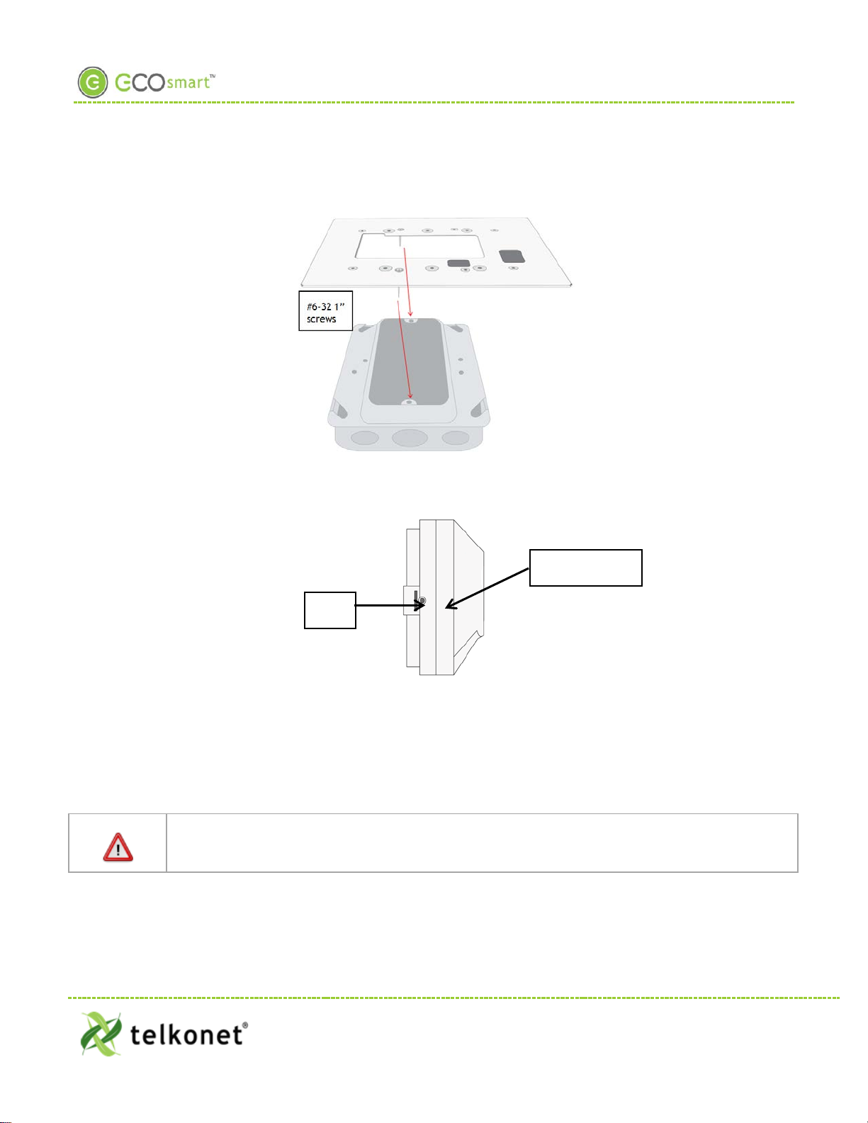
Sa fety Screw
Tab
EcoSource High Voltage Installation
Figure 5: JBOX, Mud Ring, Adapter Plate
Step 10 Remo ve the safety screw from the left side of the thermos tat usi ng the hex wrench. See Figure
6.
Figure 6: EcoSource Side View
Step 11 S epa rate the hi gh voltage back plate from the thermos ta t: Use a flathead screwdriv er to
GENT LY pres s the tab next to the screw hole to a llow the thermostat to pop open.
WARNING: Using too much force can brea k the tab.
Step 12 Place thermostat backplate against the JBOX adapter plate. The adapter plate and backplate
holes s hould align if both are correctly ori ented.
Therm ostat wiring cannot touch or be placed i n close pr ox imi ty to th e J7 pins! This can occur if
the wiring enters the thermos tat from the J8 hole and i s placed diagonally, directly ov er the J7
pins.
Step 13 C onnect ea ch 16-gauge wire (pre-i nsta lled on the therm os tat’s high-vo lt a g e ba c k pla t e ) to the
matching functional wire within the JBOX, using appropriately size d wire nuts o r a NEC-
EcoWave Fea t ur i ng EcoTouch IO&M Guide Telkone t, Inc.
For Use with Firmware Version 2.x 20800 Swenson Drive, S uite 175
EcoSource Waukesha, WI 53186
Revision 2 (800) 380-9640
Page 9 www.telkonet.com
Page 13
EcoSource High Voltage Installation
approv ed electrical connection ins ide the junction box. If a site-specific wiring diagram was
provi ded, refer to this for wiring. If no di agram was provided, refer to Figure 7.
. (If controlling proportional valve or ECM fan, see Appendix A.) Any unuse d wires mu st be capped a ccordin g
to NEC standa rds.
For v ariable output connections, see Appendix A on page 39.
1
Figure 7: Wiring
1
The High Vol tage backplate com es with R, Switched Power 1 and Switched Power 2 jum ped together with a Red Wire nut. These can be
connected to the same power source assum ing all controll ed Fans and Val ves will be controll ed at the sam e vol tage that wil l be powering
the the rm os tat . If a different voltage wil l be used for any of the Control l ed elem ents of the HVAC then the appropriate power source
should be connected to the Switched Power 1 (W1,Y1) and Switched Power 2 (G,O,W2) t ermina ls .
EcoWave Fea t ur i ng EcoTouch IO&M Guide Telkone t, Inc.
For Use with Firmware Version 2.x 20800 Swenson Drive, S uite 175
EcoSource Waukesha, WI 53186
Revision 2 (800) 380-9640
Page 10 www.telkonet.com
Page 14

2nd Stage Cool ing
9
S witched Power 2
Provides alternate power for G, O, and W2
EcoSource High Voltage Installation
Table 1-Wiring:
Pin Lab el on Backplate Function
1 R ( Powe r) 12-277VAC power from HVAC, used to power the thermostat
2 C (Common) AC Com mon
3 AUX (Auxiliary) User defi ned
4 W1 (Heat) (Strip) He at call or strip heat call (depends on programming )
5 Switched Power 1 (W1/Y1) Provides alternate pow er for W1 and Y1
6 Y1 (Cool) (Comp) Cool/Compress or call
7 G (Fan) Fan Call - L ow speed
Multi-use - depends on prog ram mi ng and s it e requi reme nts :
8 O (B) (G2) (Y2) (Changeover)
• Changeover
nd
• 2
Stage Fan
•
Multi-use - depends on prog ram mi ng and s it e requi reme nts :
W2 (Y2) (G2) (G3) (Mul ti-speed)
10
nd
• 2
stage heat
• Electric heat (for HPs with s tr ip heat, etc.)
•
Emergency heat
Step 14 Carefully push the wired connections back into the JBOX.
Step 15 M ount pre-wired 16 gauge SS6000 backplate on top of JBOX adapter, using four #5 ½” coarse
thread s crews. See Figure 8.
Figure 8: Backplate on Adapter Plate
Step 16 E nsure no airf low f rom JBOX or wa ll cavi ty is a ble to seep into the thermosta t through the wire
harnes s . Telkonet recomm ends the us e of UL caulk or UL rated insulating tape as s hown i n
Figure 9 to avoid fals e temperature readings.
EcoWave Fea t ur i ng EcoTouch IO&M Guide Telkone t, Inc.
For Use with Firmware Version 2.x 20800 Swenson Drive, S uite 175
EcoSource Waukesha, WI 53186
Revision 2 (800) 380-9640
Page 11 www.telkonet.com
Page 15

EcoSource High Voltage Installation
Figure 9: Backplate with UL-Rated I nsulating Tape
Step 17 Line up the hinges on the thermostat to the notches on the backplate:
Figure 10-Line Up Hing es on Right
Step 18 Pres s the right si de of the th ermos tat ti ghtly a ga ins t the back plate.
Step 19 Slowly br ing the lef t side toward the w all. Us e care not to force the faceplate closed. I f you
encounter resistance, check to make sure no wires are pinched between components.
Caution: the metal pins (as show n in Figure 11) can be bent when replacing faceplates if too
much force is used.
EcoWave Fea t ur i ng EcoTouch IO&M Guide Telkone t, Inc.
For Use with Firmware Version 2.x 20800 Swenson Drive, S uite 175
EcoSource Waukesha, WI 53186
Revision 2 (800) 380-9640
Page 12 www.telkonet.com
Page 16

EcoSource High Voltage Installation
Figure 11: Metal Pins
Step 20 R eturn the electrical circuit to operatio n. R emov e all lock outs or tags from the circuit breaker
and enable any dis connects.
Step 21 Veri fy the EcoS ource thermos ta t dis play is a ctiv e.
Step 22 Test all components to make sure that you can engage both the heat and air conditioning, and
all supported fan s e ttings (high, l ow , etc .). Wiring is comp l et e.
Step 23 Once the thermo sta t has been s napped o nto the backplate, use a hex wrench to insert the
sa fety screw.
EcoWave Fea t ur i ng EcoTouch IO&M Guide Telkone t, Inc.
For Use with Firmware Version 2.x 20800 Swenson Drive, S uite 175
EcoSource Waukesha, WI 53186
Revision 2 (800) 380-9640
Page 13 www.telkonet.com
Page 17

EcoSource Low Vo ltage Insta lla tion
Low Voltage Installation
Always ensure power has been turned off befor e starting installation.
EcoSource Low Voltage Requi red Equ ipmen t
• EcoSource (P/N: SS6500)
• EcoTouch (P/N: SS 6560)
• Voltmeter
• Level
• Phillips Hea d S crewdriv er
• Precisi on S crewdriv er
• UL rated insulating tape
• Wire stripper
• Wire nuts
Addi tio nal H ard wa re R eq uire d for D rywa ll M oun t
• Four 50 lb. EZ-L ock a nchors a nd prov ide d scre ws
Additional H ardware Required for VERTI CAL JBOX Mount
• Telkonet JBOX Adapter Plate
• T wo # 6 -32 1” screws
• Four $5 ½” coarse thread screws
Additional Hardware R equired for H OR I ZONT AL JBOX Moun t
• T wo # 6 -32 1” screws
• 1 Speed Nut (flat-type speed nut fastener that accommodates a #6-32 1” screw as shown in Figure
12.
Figure 12-Speed Nut
Installation Instructions Common to All Three Low Voltage Options
Step 1 If applicable, determi ne the location in the room where the thermos tat will be i nsta lled. ( See
EcoTouch Therm os tat Locati on Planning s ection, page 24.)
EcoWave Fea t ur i ng EcoTouch IO&M Guide Telkone t, Inc.
For Use with Firmware Version 2.x 20800 Swenson Drive, S uite 175
EcoSource Waukes ha , WI 53186
Revision 2 (800) 380-9640
Page 14 www.telkonet.com
Page 18

EcoSource Low Voltage Installation
Step 2 Turn off power at EcoSource mounti ng location us ing a dis connect s witch or breaker lockout/tag
out on appropr iat e break er pa nel.
Step 3 Test that power is off by using a voltmeter.
Step 4 Remo ve the safety screw from the left side of the thermos tat using the hex wrench. See Figure
13.
Figure 13: EcoSource Side View
Step 5 Sepa rate the backplate f rom the thermostat: Use a f lathead s crewdriv er to GENT LY press the
tab nex t to the s crew hole to allow th e thermos tat to pop open. W ARNING: Using too much
force c an brea k the tab.
Step 6 For drywall m ounting ins tructi o ns, go to S te p 7.
For JBOX ver tical ins tallation instruction s, go to Step 19
For JBOX horizontal installation ins tructions , go to Step 30
Therm ostat wiring cannot touch or be placed in close proximity to the J7 pins! This can occur if
the wiring enters the thermostat f rom the J8 hole and is placed diag onally, directly ov er the J7
pins.
Drywal l Mounti ng Instr uctio ns
• Requires four 50 lb. EZ-L ock anchor s and prov i ded s crews
Step 7 Hold backplate against wall at appropriate height. Using a pen, level-mark your 4 holes .
Step 8 Use appropriate drill for a nchor and insert anchors into holes.
Step 9 Screw backplate to the wall and i nto the anchors . Re-ch ec k t ha t i t is s t i ll leve l.
Step 10 Strip the LINE wire ba ck 0.25 inches.
Step 11 Cap the LINE wire with a wire nut or electrical tape.
Step 12 Cut the COMM O N wire s o the copper is flush with the ins ulation.
Step 13 Stri p all wires ex cept for COM M ON back 0. 25 inches.
Step 14 Verify the wiring now looks similar to Figure 14.
EcoWave Fea t ur i ng EcoTouch IO&M Guide Telkone t, Inc.
For Use with Firmware Version 2.x 20800 Swenson Drive, S uite 175
EcoSource Waukesha, WI 53186
Revision 2 (800) 380-9640
Page 15 www.telkonet.com
Page 19

EcoSource Low Voltage Installation
Figure 14-Wiring
Step 15 S tarting at the bo ttom of th e termi nal blo ck and worki ng up, us e a precis i on s crewdriver to
secure ea ch of the wires i nto the appropriate pi ns on the terminal block. Low v olt a g e o nly :
Using 20-18 g auge wire, leave a minimum of 8” of spare wire exposed fr o m the wall for
connection directly to the thermos tat’s back plate s crew termi nals.
Step 16 Lo w volt age only: En sure backplate has appropriat e jumpers between R, SW1 and SW2. If
ins talling on a heat pump, ensure there is a jumper between Y1 and W 1. See Figure 15.
Figure 15: EcoSource Backplate with Appropriate Jumpers
Step 17 Verif y ea ch wire is s ecure by gently tugg ing on it.
Step 18 C ontinue to Step 41
JBOX Using Vertical Mud Ring Instructions
• Requires Telkonet JBOX Adapter Plate and two #6-32 1” screws
Step 19 Strip the LINE wire ba ck 0.25 inches.
Step 20 Cap the LINE wire with a wire nut o r e lectrical tape.
Step 21 Cut the COMM O N wire s o the copper is flush with the ins ulation.
Step 22 Stri p all wires ex cept for COM M ON back 0. 25 inches.
EcoWave Fea t ur i ng EcoTouch IO&M Guide Telkone t, Inc.
For Use with Firmware Version 2.x 20800 Swenson Drive, S uite 175
EcoSource Waukesha, WI 53186
Revision 2 (800) 380-9640
Page 16 www.telkonet.com
Page 20

EcoSource Low Voltage Installation
Step 23 D etermine which end of the adapter should be situa ted on top, and whi ch end s hould be
s ituated on the bottom. As shown in Figure 16, the notch in the main display should be in the
upper left corner, and the smaller, vertical rectangle should be in the lower right corner.
Figure 16: Determ ine Top & Bottom of Plate
Step 24 Mount the T elk onet JBOX adapter plate to the mud ring with two #6-32 1” screws. S ee Figure
17.
Figure 17: JBOX, Mud Ring & Adapter Plate
Step 25 Mo unt SS 60 00 back plate on top of JBOX adapter, us ing four #5 ½” coarse thread screws. See
Figure 18.
EcoWave Fea t ur i ng EcoTouch IO&M Guide Telkone t, Inc.
For Use with Firmware Version 2.x 20800 Swenson Drive, S uite 175
EcoSource Waukesha, WI 53186
Revision 2 (800) 380-9640
Page 17 www.telkonet.com
Page 21

EcoSource Low Voltage Installation
Figure 18: Back Plate on Adapter P l ate
Step 26 Connect each WECO terminal to the ma tching functio nal wire within the JBOX. R efer to Figure
19 and Table 2. (If controlling proportional valve or ECM fan, see Appendix A .) A ny unused wires
must be capped accor ding to NEC standa rds.
Figure 19: Wiring
For v ariable output connections, see Appendix A on page 39.
EcoWave Fea t ur i ng EcoTouch IO&M Guide Telkone t, Inc.
For Use with Firmware Version 2.x 20800 Swenson Drive, S uite 175
EcoSource Waukesha, WI 53186
Revision 2 (800) 380-9640
Page 18 www.telkonet.com
Page 22

Pin
Label on Bac kp late
Function
1
R (Power)
12-277VAC power from HVAC, used to power the thermostat
3
AUX (Auxiliary)
User defi ned
4
W1 (He at) (St rip)
He at call or strip heat call (depends on programming )
6
Y1 (Cool) (Comp)
Cool/Compressor call
7
G (F an)
Fan Call - L ow speed
EcoSource Low Voltage Installation
Table 2: Wiring
2 C (Common) AC Com mon
5 Switched Power 1 (W1/Y1) Provides alternate power for W1 and Y1
Multi-use - depends on prog ram mi ng and s it e requi reme nts :
8 O (B) (G2) (Y2) (Changeover)
• Changeover
nd
• 2
• 2
Stage Fan
nd
Stage Cool ing
9 S wit ched Powe r 2 Provides alternate power for G, O, and W2
Multi-use - depends on prog ram mi ng and s it e requi reme nts :
W2 (Y2) (G2) (G3) (Multi-speed)
10
nd
• 2
stage heat
• Electric heat (for HPs with s tr ip heat, etc.)
• Emergency heat
Step 27 Low voltag e only: ens ure backplate has appropriate jumpers between R , SW 1 and S W 2. If
ins talling on a heat pump, ens ure there i s a jumper between Y1 and W 1 . S ee Figure 15 on pag e
16.
Step 28 Ens ure no airf low from the JBOX or wall cav ity is a ble to s eep i nto the thermos tat throug h the
wire harness. Telkonet recommends the use of UL approved caulk or UL ra ted ins ulating tape t o
avoid false temperature readings. Figure 20 i llus trates s ections of insulating tape on the
backplate, covering the wall opening.
Step 29 C ontinue to Step 41
EcoWave Fea t ur i ng EcoTouch IO&M Guide Telkone t, Inc.
For Use with Firmware Version 2.x 20800 Swenson Drive, S uite 175
EcoSource Waukesha, WI 53186
Revision 2 (800) 380-9640
Page 19 www.telkonet.com
Page 23

(Preferred method for low voltage new construction)
EcoSource Low Voltage Installation
Figure 20: EcoSource B ackplate with UL-Rated Insulating Tape
JBOX Using Horizont a l Mud R ing Instructions
Requires:
• Speed nut that a ccommodates a #6-32 1” screw.
• two # 6-32 1-inch s cre ws
• 1 hole to be drilled i nto backplate (dri lling perf orme d ons ite or by Te lkonet Pr oductio n pri or to
shipping if reques t ed in a dvance.)
Step 30 Ensure the JBOX has been installed with a horizontal mud ring .
Step 31 Unless thi s was done pri or to s hippi ng , drill a hole in backplate a s show n in Figure 21. The
horizontal dis tance between the hole a nd the inner right s ide of the plate sho uld be 1.0” . The
vertical distance between the hole and the inner right side of the plate should be 1 ¾”. The
hole should accommodate a #6-32 1” screw.
EcoWave Fea t ur i ng EcoTouch IO&M Guide Telkone t, Inc.
For Use with Firmware Version 2.x 20800 Swenson Drive, S uite 175
EcoSource Waukesha, WI 53186
Revision 2 (800) 380-9640
Page 20 www.telkonet.com
Page 24

EcoSource Low Voltage Installation
Figure 21: EcoSource Backplat e with Speed Nut an d Drilled Hole
Step 32 Lev el the backpla te usi ng a pen level across the bottom of the backplate.
Step 33 Place the speed nut on the backplate in the posi tion shown in Figure 21, with the prongs
pointing inward toward the mud ring .
Step 34 Place the screw i n the s peed nut hole.
Step 35 Driv e the screw into the mud ring . Use your f inger s to ho ld the speed nut in place, to prev ent it
from turning a s the screw is driv en. (T he curve of the speed nut allows the head of the screw to
be slig htly reces s ed into the backplate.)
Step 36 Mount the other screw in the ho le on the right side of the backplate.
Step 37 S tarting at the bottom of the terminal blo ck and working up, us e a precis ion s crewdriver to
secure ea ch of the wires i nto the appropriate pi ns on the terminal block. For low v oltage, us ing
20-18 gauge wire, leave a minimum of 8” of wire exposed f r o m the wall for connection directly
to the thermos tat’s back plate W EC O term inals .
Step 38 Low voltage only: Ensure backplate has appropriate jumpers between R, SW1 and SW2. If
ins talling on a heat pump, ensure ther e is a jum per between Y1 and W 1. S ee Figure 15 on pag e
16.
Step 39 Verify each wire is secure by gently tug gi ng on it.
Step 40 Ensure no airflow from the JBOX or wall cav ity is a ble to seep into the thermo sta t throug h the
wire harnes s. Telkonet recomm ends the us e of UL caulk or UL rated insulating tape to av oid
false tempera ture reading s. Figure 20 on pag e 20 illus trates s ections of i nsulating tape on the
backplate, covering the wall opening.
Instructions Common to All Three Low Voltage Options
Step 41 Hoo k the thermostat to the hinges on the r ight s ide of th e backpla te, as shown Figure 22.
Figure 22-Line Up Hing es on Right
Step 42 Li ne up the hinges on the therm osta t to the notches on the backplate. Pres s the rig ht s ide of
the thermo sta t tig htly ag ains t the back plate.
Caution: when replacing thermostats, the metal pins (as shown in Figure 23) can be bent if too
much force is used.
EcoWave Fea t ur i ng EcoTouch IO&M Guide Telkone t, Inc.
For Use with Firmware Version 2.x 20800 Swenson Drive, S uite 175
EcoSource Waukesha, WI 53186
Revision 2 (800) 380-9640
Page 21 www.telkonet.com
Page 25

EcoSource Low Voltage Installation
Figure 23: Metal Pins-Use Care
Step 43 Slowly bring the left side toward the wall as shown. Use care not to force the faceplate closed.
If you encounter res is tance, ens ure no wires are pinched between com ponents and tha t no pins
are bent.
Step 44 Once the thermos tat has been snapped onto the back plate, us e a hex wrench to insert the
sa fety screw in the locati on s hown in Figure 13 on page 15.
Step 45 Inside the PTAC, verify the GFI (if so equipped) has not been tripped.
Step 46 Verify that the PTAC has been set to Class II (remote thermostat) operation (i f applicable).
Consult PTAC manual for proper procedure.
Step 47 Rei nsert and tighten the safety screw on the EcoSource.
Step 48 Rem ov e all lockouts or tags f rom the circuit break er.
Step 49 Return the electrical circui t to operati on.
Step 50 Verify the therm os tat dis play is activ e.
Step 51 Test all components to make sure that you can engage both the heat and air conditioning, and
all supported fan s e ttings (high, low, etc.). Wiring is complete.
Step 52 Continue to EcoTouch Wireless Installation section.
Relay Configuration
The therm o stat comes with a default relay configuration, which s e ts the functions of each pin. This default can
be changed to one of sev eral a lternate relay confi gurati ons , which a re stored i n the memory of the thermos tat.
To change your thermos tat relay confi gura tion, s pecifi cally comm and #2.
J5 Connector
The functi o ns of the J5 Conne ctor will vary base d on the device model.
EcoWave Fea t ur i ng EcoTouch IO&M Guide Telkone t, Inc.
For Use with Firmware Version 2.x 20800 Swenson Drive, S uite 175
EcoSource Waukesha, WI 53186
Revision 2 (800) 380-9640
Page 22 www.telkonet.com
Page 26

only)
Amperage
Amperage
Amperage
EcoSource Low Voltage Installation
Table 3: J5 Connector Pinout
Pin Wire Color Label on Backpl ate Function
1 OR GND
2 BR +10V 10 Volts DC O u tput
3 RD NTC Probe 1 Temperature Probe 1
4 RD NTC Probe 1 Temperature Probe 2
5 * WH 0-10v/4-20mA out 1
6 * BK 0-10v/4-20mA out 2
7 BR CT Input 1
8 YL CT I nput 1
9 † BK CT input 2
10 † GR
11 † BL
CT input 2 Current T ransformer Input for
CT input 3
Therm osta t Si gna l Ground ( not
an earth ground)
Analog Output # 1 (VO model
only)
Analog Output # 2 (VO model
Current T ransformer Input for
Amperage
Current Trans former Input for
Current T ransformer Input for
Amperage
Current T ransformer Input for
12 † OR
CT input 3 Current T ransformer Input for
Amperage
EcoWave Fea t ur i ng EcoTouch IO&M Guide Telkone t, Inc.
For Use with Firmware Version 2.x 20800 Swenson Drive, S uite 175
EcoSource Waukesha, WI 53186
Revision 2 (800) 380-9640
Page 23 www.telkonet.com
Page 27

EcoTouch Installation
EcoTouch
The EcoTouch is a remote thermosta t that communicates with the EcoSo urce v ia the wireless Zig Bee mes h
network. It comes with a built-in temperature sensor and IR occ upancy sensor. An optional humidity sensor
may also have been ins talled into the EcoTouch.
EcoTouch Lo cati on Planning
Actual therm osta t mounting heig ht can va ry between s ites depending upon furnis hing s and aesthetic
consi derations . T he standard recommended heig ht is approxi mately 60 ” from fini s hed f loor. Any rooms
des ig nat ed as A DA sho uld be m ounte d abov e 1 5” and below 4 8” . See Figure 24.
Figure 24: Mounting Height
EcoWave Fea t ur i ng EcoTouch IO&M Guide Telkone t, Inc.
For Use with Firmware Version 2.x 20800 Swenson Drive, S uite 175
EcoTouch Waukes ha , WI 53186
Revision 2 (800) 380-9640
Page 24 www.telkonet.com
Page 28

(e.g. sleeping in bed)
(e.g . walking in ha ll)
Sho uld point toward mai n sleeping a rea
sho uld always be positioned within a 12’ radius from the f ront of the thermos ta t
Project Manager.
provides proper ai rflow.
EcoTouch Installation
Table 4: EcoTouch Mounting-Bes t Pra cti ces
Mounting
Considerations
Dis tance to
Occupant
Li ne of Si ght
Best P ra ctic e
If the occupants will likely be stationary…
If the occupants wi ll mo ve occas ionally…
(e.g. working at desk)
If the occupants will move regularly…
Should not have its line of sight to the EcoSource partially obstructed by grills, registers, or
spinning fan bla des.
EcoTouch ha s 140° wide horizontal viewing angle
Position within 0 – 9 feet of thei r expected
location.
EcoTouch: within 9-18 feet of their
expected location
EcoTouch: within 1 8-25 feet of thei r
expected location
If no door contacts or remote occupancy sensors are us ed in the gues t room then the bed
Should be mounted on a wall away from heat or cold sources that could affect its
temperature reading. This includes direct s unlight, outside-facing walls with poor i nsulation,
walls wit h hot and cold riser piping, and walls near radiators.
Other
Considerations
Where possible, mount on an inside wall.
If a suitable location without a heat or cold source is not available, contact a Telkonet
Should be mounted on th e wall, not set into the wall. T his will ens ure tha t the ba ckplate
EcoWave Fea t ur i ng EcoTouch IO&M Guide Telkone t, Inc.
For Use with Firmware Version 2.x 20800 Swenson Drive, S uite 175
EcoTouch Waukes ha , WI 53186
Revision 2 (800) 380-9640
Page 25 www.telkonet.com
Page 29

EcoTouch Installation
Installation
Eco To uch ca n a ccept 24 VAC or 12 -14VDC on J2.
Use wire harnesses wi th red and black s tri pped wire s and JARD J4021F trans formers, both provided
by Telkonet. (Exceptions may apply in certain circumstances.)
Step 1 Review t able on page 25 to determine where the EcoTouch wi ll be m o u nt e d.
Step 2 Remo ve the security screw fro m the EcoTouch (see Figure 25).
Figure 25-Secur ity Screw
Step 3 Sepa rate the backplate f rom the EcoTouch by slidin g the backplate to the right and the front
plate to the left (approximately ¼ inch), as shown in Figure 26.
Figure 26: Slide Top Left, Bottom Right
EcoWave Fea t ur i ng EcoTouch IO&M Guide Telkone t, Inc.
For Use with Firmware Version 2.x 20800 Swenson Drive, S uite 175
EcoTouch Waukesha, WI 53186
Revision 2 (800) 380-9640
Page 26 www.telkonet.com
Page 30

EcoTouch Installation
Step 4 Lift the front plate up and off of the back plate as s hown in Figure 27.
Figure 27: Lift Up and Off
Step 5 Lev el the backplate on the wall.
Step 6 Ma rk the placement fo r the mounting s crews .
Step 7 Mo unt the backplate to the wall us i ng the mounting s crews.
Step 8 Note the J2 pin as shown in Figure 28; this is the pin to which you will connect power.
Step 9 Note the J2 wires coming out fro m the wall.
Step 10 You w i ll a t tach the J2 wires to th e J2 pin.
Figure 28: J2 Pin
EcoWave Fea t ur i ng EcoTouch IO&M Guide Telkone t, Inc.
For Use with Firmware Version 2.x 20800 Swenson Drive, S uite 175
EcoTouch Waukesha, WI 53186
Revision 2 (800) 380-9640
Page 27 www.telkonet.com
Page 31

EcoTouch Installation
-If your power is a n A C 24V transf ormer, then connect the red wire and bla ck wire to the top 2 pins; i t does
not ma tter whether the red wire is on top a nd the black wire is in the 2
vice versa.
nd
slot from the top, or
-If your power is a 12-2 4VDC ins tallation, then connect the black wire to the top pin (thi s is the “Ground” or
“Common” pin) and connect red wire to the 2
nd
pin-the pin j ust below the top pin (this is the “Power” pin).
Step 11 Place the cover over the back plate, about ¼ inch to the left as shown in Figure 29.
Figure 29: Replace Cover
Step 12 Slide the cov er to the right to secure i t.
Step 13 Screw in the s ecurity screw.
Your EcoTouch is now installed.
EcoWave Fea t ur i ng EcoTouch IO&M Guide Telkone t, Inc.
For Use with Firmware Version 2.x 20800 Swenson Drive, S uite 175
EcoTouch Waukesha, WI 53186
Revision 2 (800) 380-9640
Page 28 www.telkonet.com
Page 32

Current Indoor tem perature
Display
Setpoint
Display
Ge ar Ico n
Adjust screen brightness; language selection (see below for details)
Increas e/Decrease S etpoint
Press up and down arrows to adjust setpoint withi n the perm itted rang e
on 3-day for ecast s creen)
Ec o Touc h G uest Interface
EcoTouch Guest Screen Controls & User Interface
Figure 30: Guest Screen Controls
The EcoTouch front panel controls a re sho wn below. The A dmini s tration controls can be locked out of
operation, so they are not visible until a spe cif i c unlock s eq uen ce i s entered. Currently this is the 3-f ing er t ap
as referenced on page 31.
On/Off Turn the system on and off (Optional: On/Heat/Cool/O ff)
Fan C o ntrol Press to cycle through available fan speeds: Low, Medium, High, Auto
Fahrenheit/Celsius Tog gle between Fahrenheit and Cels ius temperature display (not f unctional
Current Weather Displays current outdoor weather; touch for 3 -day forecast (see below for
details)
EcoWave Fea t ur i ng EcoTouch IO&M Guide Telkone t, Inc.
For Use with Firmware Version 2.x 20800 Swenson Drive, S uite 175
EcoTouch Waukesha, WI 53186
Revision 2 (800) 380-9640
Page 29 www.telkonet.com
Page 33

Ec o Touc h G uest Interface
Weather Forecast
• Provides a three da y forecast
• Dis plays hig h and low temperature
• Dis plays weather graphi c indicting weather conditi ons ( s unny, cloudy, ra iny, etc.)
• Dis plays day of the week
• Updates daily
Adjus t Screen B ri ghtnes s
Touch Gear icon > To uch Display Dimming > Select Dim at Night or Off at Night > Back Arrow twice to exit
La nguage Sel ectio n
Touch Gear icon > Select Language > Press u p/ down ar r ows to s elect Englis h, S panis h, French or Portugues e >
Back Arrow twice to exit
EcoWave Fea t ur i ng EcoTouch IO&M Guide Telkone t, Inc.
For Use with Firmware Version 2.x 20800 Swenson Drive, S uite 175
EcoTouch Waukesha, WI 53186
Revision 2 (800) 380-9640
Page 30 www.telkonet.com
Page 34

8. Bind routers and end devi ces (such as Control4, Sa flok, etc.) in the room.
EcoTouch Pairing
Device Association
Remi nder: as s ociating dev ices m ust be done in this order:
1. Set up EcoCommander.
2. Hard wire EcoConnect coordinators to the EcoCommander.
3. Create a network vi a the EcoConnect coordinator.
Pair EcoTouch with EcoSo urce
1. On the EcoTouch, “three-fing er tap” anywhere o n the s creen. ( “Thre e-finger tap” m e ans to touch the
screen using 3 fingers, simultaneously; slightly spread out your fingers so all three fingers are
recognized by the screen.)
2. The System Status screen appears .
3. Press the Config button.
4. Enter t he pas s word C 57A
5. Touch Enter.
6. Touch Pair.
7. On EcoSource, use a paperclip or pen to press the recessed button above the LED light one time (LED
will turn solid red).
8. Touch Search on EcoTouch.
9. Ec oT ouc h will indicate “Searching for a thermostat to pair…”
10. “S uccess ” mess ag e will appear: your EcoTouch is now pai red to the EcoS ource.
11. Back out of the screen by press ing Exit, then Exit, then Exit once ag ain.
4. Join routers (e.g. EcoSources) to the EcoConnect coordinator.
5. Pair EcoTouch to EcoSource (see details below).
6. Pair EcoContact to EcoSource (if a pplicable).
7. Pair EcoSense to Eco S our ce ( if applica ble) .
If fail, will show message, “ERROR! Failed to pair. No open EcoSource found.”
Typically the cause of the failure is that the EcoSource is not yet enabled for pairing.
S olution: Repeat the a bove s teps , pa rticularly S tep 7.
See the Device Assoc iatio n Gu ide for det ail ed instructions on associating all devices.
EcoWave Fea t ur i ng EcoTouch IO&M Guide Telkone t, Inc.
For Use with Firmware Version 2.x 20800 Swenson Drive, S uite 175
Waukes ha , WI 53186
Revision 2 (800) 380-9640
Page 31 www.telkonet.com
Page 35

EcoTouch Configuration Changes
EcoTouch Configuration Changes
Change Channel
1. On the EcoTouch, “three-fing er tap” anywhere o n the s creen.
2. The System Status screen a ppears.
3. Press the Config button.
4. Enter t he pas s word C 57A
5. Touch Enter.
6. Touch Reconnect
7. Touch Search
8. When “Success” message appears, press Exit, press Exit on th e n ext s c r een an d Exit on the thir d
screen.
Unpair EcoTouch
1. On the EcoTouch, “three-fing er tap” anywhere o n the s creen.
2. The System Status screen a ppears.
3. Touch the Config button.
4. Enter t he pas s word C 57A
5. Touch Enter.
6. Touch Unpair.
7. Touch Delete.
8. Are you s ure you want to delete pairing with E coSource? T ouch Delete
9. When the “No longer Paired” message appears, touch Exit, touch Exit on the next s creen and Exit on
the third s creen.
Activate “Displ ay Mode” Option
1. On the EcoTouch, “three-finger ta p” anywhere on the screen.
2. The System Status screen a ppears.
3. Press the Config button.
4. Enter t he pas s word C 57A
5. Touch Enter
6. Touch Display /Config
7. Enable Demo Mode field: touch the pencil i con to select “Y” or “N”
8. Display Style field: touch the pencil icon to select “Detailed” or “Minimal”
9. Touch Exit
FYI, touch the ham burger i con to togg le between Detailed and Minimal dis play modes.
Sys tem Stat us Scr een
(Displays Firmware Version, MAC, EPID, Channel, Address , LQI and Paired status.)
1. On the EcoTouch, “three-fing er tap” anywhere o n the s creen.
2. The System Status screen a ppears.
3. Touch Exit when done.
EcoWave Fea t ur i ng EcoTouch IO&M Guide Telkone t, Inc.
For Use with Firmware Version 2.x 20800 Swenson Drive, S uite 175
Waukesha, WI 53186
Revision 2 (800) 380-9640
Page 32 www.telkonet.com
Page 36

EcoTouch Configuration Changes
Regular Maintenance
Under norm al conditi ons, a correctly deployed EcoS mart s eri es will require no mai ntenance.
Procedure: Visual Inspection
St ep 1 Verify that components have not been tampered with, destroyed or stolen.
St ep 2 Verify tha t the components ar e securely mounted on their r espectiv e s urfaces .
St ep 3 Verify that the AC power is being supplied to the HVAC system.
St ep 4 Verify tha t the power/data wiring between the EcoSource and the EcoTouch are intact and
connected.
St ep 5 Re-associate all sensors.
Procedure: Functional Inspection
St ep 1 Observe whether the HVAC system is operating (e.g. drive cycle) after entering the room.
In mo st cases, entering the room will have initiated an HVAC drive cycle after the Sensor detected
occup an cy. Pos s i ble ex ce pti on s :
-If the temperature in the room is within hysteresis of the HVAC setpoint, a drive cycle may not
commence;
-A dela y may have been program med into the EcoSource therm os tat, i ns tructing the unit to wait for
a particular durati on before triggering a drive. (Although uncommon, this feature is sometimes
requested by a property. In almost all cases, the delay is less than 3 minutes.)
St ep 2 If a driv e cycle does not initi ate within 5 minutes of entry, force a drive cycle by temporarily
s etting the thermo sta t to s ome arbitrar y high or low temperat ure (ens ure the H VAC mode is set
correctly).
EcoSource thermos tats def ault to Occupied status if communic ation with the Sensor(s) is lost for any
reason. This permits the units to continue allowing the occupant to control the room temperature.
However, in this state energy savings will be lost. If in doubt whether the sensors ar e associated, reassociate all Sensors.
EcoWave Fea t ur i ng EcoTouch IO&M Guide Telkone t, Inc.
For Use with Firmware Version 2.x 20800 Swenson Drive, S uite 175
Waukesha, WI 53186
Revision 2 (800) 380-9640
Page 33 www.telkonet.com
Page 37

GF I wi thin the HV A C ha s t ri pp ed. S ome
PTA C / PT HP uni ts ) conta i n i nt egr a l G FI
Troubleshooting
Problem Potential Cause Potentia l Solution
Ma in electri cal fa i lure to the uni t.
Many units operate on 230 or 277VAC
HVAC uni t does not opera te .
circuits, so although power is av ailable
to the 1 1 0 V A C plug s in the room, the
bra nch circui t suppl yi ng HVA C power
m a y be i nterrupted.
m odels of HVAC systems (of ten
(Ground-Fa ul t Interrupt) sys tem s.
Occasionally, oft en a f t er a pow er
outag e, inrush curre nt when powe r
returns can cau se GF I s to trip. Most
times, thi s does not i ndicate issues
wi th t he uni t.
Dispat ch m a intenance. V eri fy m ains
conti nuity to the uni t.
Check a nd reset units’ GF I system s.
Replace the EcoSource with a knowngood u ni t a s a com parison-check.
If the replacem ent unit functi on s
EcoSource has failed.
properly, contact T el kone t a nd begi n
the RMA process.
If the replacem ent unit does not
function properly, consult a local HVAC
technicia n t o i nsp e c t y our H V A C uni t.
D oor conta c t i s not con necte d .
Window or ou ts i d e door i s op en.
Ensure that all door contacts are
connected.
Ens ure that no m oni tored w indows or
pa tio doors are open.
EcoWave Fea t ur i ng EcoTouch IO&M Guide Telkone t, Inc.
For Use with Firmware Version 2.x 20800 Swenson Drive, S uite 175
Appendix ATroubleshooting Waukesha, WI 53186
Revision 2 (800) 380-9640
Page 34 www.telkonet.com
Page 38

depl oy ments where t he bed pla cement
wi th t he R ecom mended Best P ra c tice s .
Troubleshooting
Problem Potential Cause Potentia l Solution
Dur i ng a n Unocc upi ed peri od , the
EcoSmart system a l l ows the
tem perature in the room to drif t a wa y
Occup a nt return s t o roo m and finds i t
too hot or too co ld.
“S ensor D ow n” message appears on
thermostat.
fr om the occupants ’ setpoint.
Tel k onet’s Recov ery Time technology is
enabled to return the ro om to the
occupants’ s etpoi nt wi thi n a ti me
defi ned i n a dvance by the property
manag er (this va ri es by property, but it
usua l ly bet ween 8 and 20 minut es) .
One or more sensors hav e l ost
associati on to the thermostat.
Adv i s e the occupa nt to wai t 8 – 20
m inutes. (Thi s is t he typ i cal rang e of
defined recov ery ti mes requested by
custom ers in m ost instal l a ti ons.)
Dispat ch Ma i nt ena nce t o the r oo m. R eassociate all sensors v i a procedu re s.
Replace the bat teries in all s ensor s
wi thin the room .
Eva l ua t e the wiring betw een ea ch
sensor and the therm osta t.
Occup a nt reports HVA C shuts down
whi le they s leep.
Occup a nt repor ts one m ode
(heating/cooling ) w orks but t he othe r
does n ot.
Sensor is not accura tel y dete cti ng
occupancy. This is typically seen in
wi thin the room was chang ed a fter
ins ta llation, such tha t the pillow area
of t he bed( s ) is f urt her tha n 10-15 feet
from the sensor.
Hea t pump jumper is rever sed or
changeover signal is backwards, or it
may be that the heat/coo l jum pers a re
reversed.
Assess the room, sensor placement,
and bed location(s ) . Veri f y that the
sensor(s) a r e deployed in accor da nce
Correcti ve stra t egies m ay incl ude:
a. Moving the sensor
b. Addi ng a n addi ti onal sensor to
accom moda t e t he new room
layout
c. Changing t he room la y out
d. Adjusting Sensor setti ngs
(contact Tel k onet to di scuss
options)
e. Adjusti ng night del ay ( conta ct
Telkonet s up por t for
assistance)
Correct jum per or chan g eo ver signa l as
necessary.
EcoWave Fea t ur i ng EcoTouch IO&M Guide Telkone t, Inc.
For Use with Firmware Version 2.x 20800 Swenson Drive, S uite 175
Appendix ATroubleshooting Waukesha, WI 53186
Revision 2 (800) 380-9640
Page 35 www.telkonet.com
Page 39

Room does not achi eve setpoi nt w i thin
Tel k onet w i ll resea rch the dep loym ent
pref erence s w ere not comm unica t e d t o
Ens ure the P TA C unit is i n good working
Serv i ce and correct inte rna l thermostat
Ens ure the P TA C unit is i n good working
thermostat
The setp oi nt cannot be ach i eved wi t h in
the current environmental conditions.
humid day, the HVAC system may not
Ens ure the P TA C unit is i n good working
Serv i ce and correct inte rna l thermostat
Troubleshooting
Problem Potential Cause Potentia l Solution
The most common cause i s tha t the
EcoSmart system i s desi gned to recov e r
the temperature wi thin a C om f ort
Zone. T he C omf ort Z one is
programm a bl e by Tel k onet, a nd i s
chosen by m anagement bef ore
installation.
The thermostat may be programmed
with setti ngs not appropria te to the
specific depl oyment scen a rio.
Contact Telkonet Custo m er Suppo rt.
his tory , a nd determi ne whet her a
completed Settings Sheet was prov i ded
to us prior to thermostat shipment.
Note tha t P rof es sional Servi ces f ees
may apply if a report ed ano maly is
l a ter d etermi ned to ha ve been caused
by def ault setti ng s w hen s pecifi c
Tel k onet p ri or t o device shi pment.
RecoveryTime.
Often a n H V AC unit is in need of
servicing. For example, a unit with a
fa ili ng compress or or under-charged
ref ri g erant m a y not be able to
eff i ciently return the room to the
occupan ts’ desired set po i nt.
There may be a f a iled control ci rc ui t
within the HVAC system
For ex a mpl e, on an ex t remely hot or
be a bl e to achi eve a set poi nt of 60°.
order.
anomal ies per PTAC manufacturer’s
recommended bes t practi ces .
order.
Serv i ce and correct inte rna l
anomal ies per PTAC manufacturer’s
recommended bes t practi ces .
order.
anomal ies per PTAC manufacturer’s
recommended bes t practi ces .
EcoWave Fea t ur i ng EcoTouch IO&M Guide Telkone t, Inc.
For Use with Firmware Version 2.x 20800 Swenson Drive, S uite 175
Appendix ATroubleshooting Waukesha, WI 53186
Revision 2 (800) 380-9640
Page 36 www.telkonet.com
Page 40

Index
Index
Figure 1: I nternal View EcoSource ............................................................................................ 5
Figure 2: Telkonet J BO X Adapter Plate ...................................................................................... 7
Figure 3: Ver tical Single Ga ng Mud Ring ..................................................................................... 8
Figure 4: D e te rmine Top & Botto m of Plate................................................................................. 8
Fi gure 5 : JBOX, Mud Ring, Adapter Plate .................................................................................... 9
Figure 6: EcoSource Side View ................................................................................................ 9
Figure 7: Wiring ............................................................................................................... 10
Figure 8: Backplate on Adapter Plate ...................................................................................... 11
Figure 9: Ba ckplate with UL-Rated Insulating Tape ...................................................................... 12
Figure 10-Line Up H inges on Right .......................................................................................... 12
Figure 11: Metal Pins ......................................................................................................... 13
Figure 12-S peed Nut .......................................................................................................... 14
Figure 13: EcoSource Side View ............................................................................................. 15
Figure 14-Wiring............................................................................................................... 16
Figure 15: EcoSource Backplate with Appropriate Jumpers ............................................................. 16
Figure 16: Determine T op & Bottom of Plate ............................................................................. 17
Figure 17: JBOX, Mud Ring & Adapter Plate ............................................................................... 17
Figure 18: Back Plate on Adapter Plate .................................................................................... 18
Figure 19: Wiring .............................................................................................................. 18
Fi g ure 20: Eco S ource Back p la t e wit h UL -Rated Insulating Tape ........................................................ 20
Fi gure 2 1: EcoSource Backplate with Speed Nut and Drilled Hole ..................................................... 21
Figure 22-Line Up H inges on Right .......................................................................................... 21
Figure 23: Metal Pins-Use Care.............................................................................................. 22
Figure 24: Mounting Height .................................................................................................. 24
Figure 25-Securit y Screw..................................................................................................... 26
Figure 26: Slide Top Left, Bottom Right ................................................................................... 26
Figure 27: Lift Up and Off ................................................................................................... 27
Figure 28: J2 Pin .............................................................................................................. 27
Figure 29: Replace Co ver .................................................................................................... 28
EcoWave Fea t ur i ng EcoTouch IO&M Guide Telkone t, Inc.
For Use with Firmware Version 2.x 20800 Swenson Drive, S uite 175
Appendix ATroubleshooting Waukesha, WI 53186
Revision 2 (800) 380-9640
Page 37 www.telkonet.com
Page 41

Index
Figure 30: Guest Screen Controls ........................................................................................... 29
Figure 31-Before Connecting ................................................................................................ 39
Figure 32-After Conn e cting .................................................................................................. 39
Table 1-Wiring: ................................................................................................................ 11
Table 2: Wiring ................................................................................................................ 19
Table 3: J5 Connector Pinout ............................................................................................... 23
Table 4: EcoTouch Mounting-Best Pract ices............................................................................... 25
EcoWave Fea t ur i ng EcoTouch IO&M Guide Telkone t, Inc.
For Use with Firmware Version 2.x 20800 Swenson Drive, S uite 175
Appendix ATroubleshooting Waukesha, WI 53186
Revision 2 (800) 380-9640
Page 38 www.telkonet.com
Page 42

Appendix A
Appendix A
Pr op or tion al Val ve Con tr ol
Applies only to the SS6000-VO model of thermostat
Figure 31-Bef or e Con n ect in g
Connecting Pins
Con tr oll in g t he Coolin g Val ve wi th a 0-10 Vol t Signal
1. Using the J5 Mol ex connector, connect Pin 5 to the Val ve 0-10v input line.
2. Connect p in 1 (GND) to the Common l ine on the valve.
Note: Y ou must also jumper p in 1 t o the 24v COMM if the valve is r eferencin g 24v Common.
Controlling Heating Valve with a 0-10 Volt Signal
1. Using the J5 Mol ex connector, connect Pin 6 to the Val ve 0-10v input line.
2. Connect pin 1 (GND) to the Common line on the valve.
Note: Y ou must also jumper p in 1 t o the 24v COMM if the valve is r eferencin g 24v Common.
Controlling an ECM F an Motor
(Firmw are must b e pre-setup to provide this output.)
• Using the J5 Mol ex connector, connect Pin 6 to the ECM Motor 0-10v input line.
• Connect p in 1 (GND) to the Common line on the ECM Motor control b oard.
Note: Y ou must also connect t he 24v COMM if t he valve is ref erencing 24v Common.
Figure 32-After Connecting
Adding Ju mpers
Place 2 jumpers side -by side on connector J6. (J6 i s located below the r adio board. S ee Figure 31.
• Place one jumper on pins 1 -> 2, as shown in Figure 32. Jum per 1->2 is for 0-10V; no jumper 4 -20mA.
• Place the other jumper on pins 3 -> 4. Ju mper 3 ->4 is f or 0-1 0V; no Jumper 4-20mA.
EcoWave Fea t ur i ng EcoTouch IO&M Guide Telkone t, Inc.
For Use with Firmware Version 2.x 20800 Swenson Drive, S uite 175
Appendix ATroubleshooting Waukesha, WI 53186
Revision 2 (800) 380-9640
Page 39 www.telkonet.com
Page 43

Appendix A
Cali brate the Analog Output to 5.0V
Equipment Needed: Voltmeter
• S e t voltmeter to D C Voltage.
• On J5, measure between Pin 1 (Orange) and Pin 5 (White).
• Chang e therm os tat mode to OFF .
• Enter A dvanced Command 35 01 and press ON/OFF.
• Enter A dvanced Command 36 36 and press ON/OFF.
• Thi s s hould cause your reading to go close to 5.0V.
• Change the value of 36 36 up or down a few values so it reads close to 5.0V. If you have to ra ise i t
more than 36 50 or lower than 36 25 , then there is an issue. Contact engineering
• Enter A dv anced C omm and 3 5 00
• Verify that i n th e OFF mode, output is approx. 0.0V.
EcoWave Fea t ur i ng EcoTouch IO&M Guide Telkone t, Inc.
For Use with Firmware Version 2.x 20800 Swenson Drive, S uite 175
Appendix A Waukesha, WI 53186
Revision 2 (800) 380-9640
Page 40 www.telkonet.com
 Loading...