

Telkom SS-10 3G User Manual
SS-10 3G
FIXED CELLULAR TERMINAL
USER MANUAL
DOC. NO: SS-10 3G-14 (Rev. 01) Page 1 of 20

Revision History:
Revision 01 Original document 12 August 2010
CONTENTS
1 INTRODUCTION .................................................................................................3
2 FEATURES .........................................................................................................4
2.1 PHYSICAL FEATURES .............................................................................................. 4
2.2 SOFTWARE FEATURES............................................................................................. 4
2.3 MAINTENANCE FEATURES ..................................................................................... 4
3 DESCRIPTION ....................................................................................................6
3.1 FRONT VIEW .............................................................................................................. 6
3.2 REAR VIEW ................................................................................................................ 6
4 SETUP ................................................................................................................7
5 SETTABLE PARAMETERS ...............................................................................8
5.1 BASIC SETUP .............................................................................................................. 8
5.2 REPORTING SETUP ................................................................................................... 9
5.3 SIM & NETWORK ..................................................................................................... 10
5.4 AUTHORIZED USER ................................................................................................ 11
5.5 HARDWARE SETTINGS .......................................................................................... 11
5.6 POWER DOWN TIME ............................................................................................... 11
5.7 CALL BARRING ....................................................................................................... 12
5.8 MISCELLANEOUS .................................................................................................... 12
5.9 CALL BACK .............................................................................................................. 12
5.10 SETUP INFORMATION ............................................................................................ 13
6 SERIAL PORT COMMANDS ............................................................................13
6.1 SIMPLIFIED SERIAL PORT COMMANDS .............................................................. 13
7 SETUP OF THE UNIT BY USING THE SS-10 TOOL.......................................14
7.1 MAIN WINDOW ........................................................................................................ 14
7.2 CALL PARAMETERS ............................................................................................... 15
7.3 CALL BACK .............................................................................................................. 16
7.4 CALL BARRING ....................................................................................................... 17
7.5 SMS OPTIONS ........................................................................................................... 18
7.6 NETWORK ................................................................................................................ 19
8 UPGRADE OF THE SS-10 3G FIRMWARE .....................................................20
9 TECHNICAL SPECIFICATIONS.......................................................................20
10 CONTACT DETAILS .............................................. Error! Bookmark not defined.
DOC. NO: SS-10 3G-14 (Rev. 01) Page 2 of 20
1 INTRODUCTION
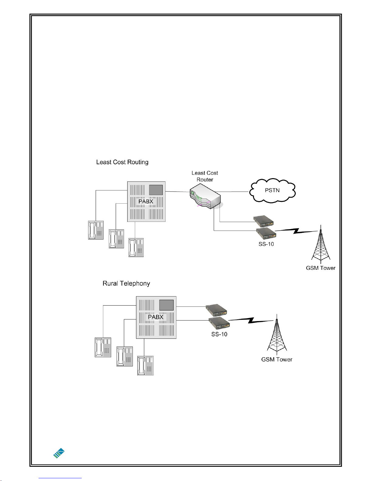
The purpose of the SS-10 3G Fixed Cellular Terminal (FCT) is to provide a means of
making telephone calls where there is no fixed line infrastructure or where it may be
more cost effective to use the GSM/3G infrastructure for carrying the call.
ARCHITECTURE
DOC. NO: SS-10 3G-14 (Rev. 01) Page 3 of 20

2 FEATURES
2.1 PHYSICAL FEATURES
Matches to complex line impedance
Power saving feed-bridge
Signal level indicator LEDs
Busy indicator
Network indicator
SMA antenna connector
Module On/Off switch allows Network Detach
Power supply 300mA at 12 VDC
RJ11 connector for telephone
DB9 connector for programming
900/1800 MHz operation in 2G GSM mode
900/2100 MHz operation in 3G UMTS mode (additional 850MHz optional)
2.2 SOFTWARE FEATURES
Comfort Tone
CLI restriction
Settable digit count
Settable dial timeout
Automatic call termination
Transmit & receive levels adjustable
Optional reversal
Optional line current break
Optional periodic module reboot
Full rate, enhanced full rate & half rate operation
Supports Adaptive Multi-rate (AMR)
Preferred network selection (Network locking)
2G, 3G or automatic network selection
Dial-In modem functionality (2G mode only)
4 minute timer to reset module if not registered on the network
128 Programmable Call Back numbers
Settable SIM Pin Number
Supports International SIM card operation
2.3 MAINTENANCE FEATURES
Routine periodic SMS reports
o Feed bridge voltages
o Number of forcedly cut calls
o Number of unanswered calls
o Number of answered calls
o Total duration of answered calls
SMS report on zero traffic (no calls made for specified interval)
Request reports
Request setting information
Change set-up information by SMS
2 authorized maintainers
DOC. NO: SS-10 3G-14 (Rev. 01) Page 4 of 20

Programmable by serial port, telephone or SMS
DOC. NO: SS-10 3G-14 (Rev. 01) Page 5 of 20
Power Indica
tor
Network Indicator
1
4
Line Connector
PC Connector
Pin Description
Inside
DC positive volta
ge
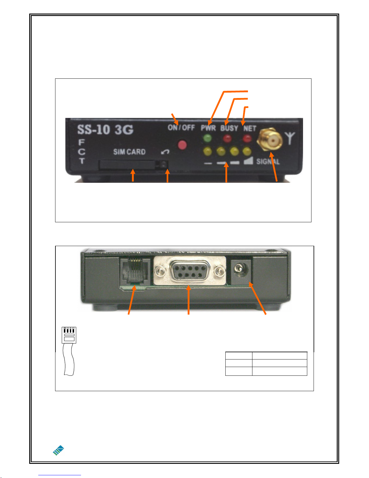
3 DESCRIPTION
3.1 FRONT VIEW
ON/OFF button
Holding in the On/Off button while the
unit is powered up enables setup mode
Busy Indicator
SIM card
tray
3.2 REAR VIEW
RJ-11 Connector
(Only pins 2 & 3
are used)
Press for
opening
Signal strength
indicator
SIM tray
DB9 Female - Used for
setup purposes
Use a standard PC
serial cable for
connecting the unit to
a PC
SMA antenna
connector
DC Connector
Connects a DC voltage
between 12V and 18V to
the unit
Outside
GROUND
DOC. NO: SS-10 3G-14 (Rev. 01) Page 6 of 20
 Loading...