

Page 1

OPTICON MICRO
Installation & Operation Manual
Page 2

OptiCon Micro
Installation and Operation Manual
Table of Contents
Abbreviation list ............................................................................................ 1
1. INTRODUCTION .......................................................................................... 2
1.1 Manual Usage ....................................................................................................... 2
1.2 Contents in Package .............................................................................................. 2
1.3 Configuration ........................................................................................................ 3
1.4 System Capability .................................................................................................. 4
1.4.1 Description ...................................................................................................................... 4
1.5 Important Safety Information ............................................................................... 5
1.5.1 Installation and Environment ........................................................................................... 5
1.5.2 Electrical Considerations .................................................................................................. 5
1.5.3 Precaution ....................................................................................................................... 5
1.5.4 Caution ........................................................................................................................... 5
2. INSTALLATION ............................................................................................ 6
2.1 Pre-Installation ..................................................................................................... 6
2.1.1 Safety Installation Instructions ........................................................................................ 6
2.1.2 Wiring Precautions .......................................................................................................... 6
2.2 DECT Installation ................................................................................................... 6
2.2.1 Introduction .................................................................................................................... 6
2.2.2 Cell Coverage................................................................................................................... 7
2.2.3 General Guidelines .......................................................................................................... 7
2.3 Battery Installation ............................................................................................... 8
2.3.1 GDC-400H Handset Battery Installation ........................................................................... 8
2.3.2 GDC-450H Handset Battery Installation ......................................................................... 10
2.4 LWS-BS, Handset and Peripheral Connections ..................................................... 11
2.4.1 FAX Connection ............................................................................................................. 13
2.4.2 AC/DC Adapter Connection ............................................................................................ 13
Page 3

OptiCon Micro
Installation and Operation Manual
2.4.3 LWS-WK Connection ...................................................................................................... 14
2.4.4 Wireless Handset Connection ........................................................................................ 15
2.4.5 Foot Stand Connection (the LWS-BS and LWS-WK) ......................................................... 16
2.5 Hardware Installation ......................................................................................... 17
2.5.1 Wall Mounting of the LWS-BS or the LWS-WK ................................................................ 17
2.6 Component Description ...................................................................................... 18
2.6.1 LWS-BS Description ....................................................................................................... 18
2.6.2 LWS-WK Description ...................................................................................................... 19
2.6.3 Wireless DECT Handset Description ............................................................................... 20
2.7 Hardware Initialization ........................................................................................ 21
2.7.1 LWS-BS and LWS-WK ..................................................................................................... 21
2.7.2 Wireless Handset ........................................................................................................... 21
2.8 Display ................................................................................................................ 21
2.8.1 LCD Specification ........................................................................................................... 21
2.8.2 LCD Display ................................................................................................................... 22
2.9 Keypad Description ............................................................................................. 23
2.9.1 LWS-BS .......................................................................................................................... 23
2.9.2 LWS-WK ........................................................................................................................ 24
2.9.3 GDC-400H/450H Wireless Handset ................................................................................ 25
2.10 LED Operation Description ................................................................................ 26
2.10.1 LWS-BS and Wireless Keyset ........................................................................................ 26
2.11 Configuration .................................................................................................... 27
2.11.1 Nation code ................................................................................................................. 27
2.11.2 LWS-BS Date and Time ................................................................................................. 27
2.11.3 GDC-400H/450H Handset Time .................................................................................... 27
2.12 Terminal Registration and Termination ............................................................. 28
2.12.1 Subscribing the GDC-400/450H / LWS-WK to LWS-BS ................................................... 28
2.12.2 Terminating a Subscriptions ......................................................................................... 29
Page 4

OptiCon Micro
Installation and Operation Manual
2.13 Menu Trees ....................................................................................................... 30
2.13.1 LWS-BS Menus ............................................................................................................ 30
2.13.2 LWS-WK Menus ........................................................................................................... 30
2.14 System Capacities .............................................................................................. 31
3. OPERATION INSTRUCTIONS ...................................................................... 32
3.1 Call Forward ........................................................................................................ 32
3.2 Call Pick-up ......................................................................................................... 34
3.2.1 Directed Call Pick-Up ..................................................................................................... 34
3.2.2 Group Call Pick-Up ......................................................................................................... 34
3.3 Call Transfer ........................................................................................................ 35
3.4 Call Waiting/Camp-On ........................................................................................ 37
3.5 LINE Access ......................................................................................................... 37
3.6 Three-Party Voice Conference ............................................................................. 38
3.7 Directory ............................................................................................................. 38
3.8 DND (Do Not Disturb) .......................................................................................... 39
3.9 Headset Compatibility ......................................................................................... 39
3.10 Hold .................................................................................................................. 40
3.10.1 Hold ............................................................................................................................ 40
3.10.2 Hold Recall .................................................................................................................. 41
3.10.3 Automatic Hold ........................................................................................................... 41
3.11 PARK Code ........................................................................................................ 41
3.12 CID Blacklist ...................................................................................................... 42
3.13 Allow/Deny Number (Call Barring) .................................................................... 42
3.14 MOH(Music-On-Hold) ....................................................................................... 42
3.15 Speed Dial ......................................................................................................... 43
3.15.1 Display Security ........................................................................................................... 43
3.15.2 Station Speed Dial ....................................................................................................... 43
Page 5

OptiCon Micro
Installation and Operation Manual
3.15.3 System Speed Dial ....................................................................................................... 44
3.16 VSF Integrated Auto Attendant/Voice Mail ....................................................... 45
3.16.1 VSF .............................................................................................................................. 45
3.16.2 Auto Attendant Announcement (DISA Service) ............................................................ 45
3.16.3 Auto Attendant Recording (Leave Voice message) ........................................................ 47
3.17 Wake-Up Alarm ................................................................................................. 54
3.18 Intercom Call (ICM Call) ..................................................................................... 55
3.19 Intercom Call Hold ............................................................................................. 56
3.20 Line Ring Assignment ........................................................................................ 56
3.21 Night/Weekend mode ....................................................................................... 57
3.22 Call Log Display ................................................................................................. 57
3.23 Mute ................................................................................................................. 58
3.24 Tel/Fax Line ....................................................................................................... 59
3.25 SLT/Fax/Modem port ........................................................................................ 59
3.25.1 Modem Operation ....................................................................................................... 59
3.25.2 SLT Hot Line ................................................................................................................. 60
3.26 Phone book (GDC-400H/450H & LWS-WK) ........................................................ 61
3.26.1 Edit CO Code................................................................................................................ 62
3.26.2 Dialing from Phonebook .............................................................................................. 62
3.26.3 Adding Records to the Phonebook ............................................................................... 63
3.26.4 Modifying Records in the Phonebook........................................................................... 64
3.26.5 Deleting records from Phonebook ............................................................................... 65
3.26.6 Dial pad Character Charts ............................................................................................ 66
3.27 Assign a feature to {Station} button .................................................................. 66
3.28 System voice mail .............................................................................................. 68
3.29 SMDR Information ............................................................................................ 68
3.30 Software Upgrade ............................................................................................. 69
Page 6

OptiCon Micro
Installation and Operation Manual
3.31 Database management ..................................................................................... 70
3.31.1 Initialize Database ....................................................................................................... 70
3.31.2 Database backup ......................................................................................................... 70
3.31.3 Database Restore ........................................................................................................ 71
3.32 Feature Codes ................................................................................................... 71
4. USEFUL INFORMATION ............................................................................ 72
4.1 Trouble shooting ................................................................................................. 72
Page 7

OptiCon Micro
Installation and Operation Manual
1
Abbreviation list
LWS-BS: LG Wireless System - Base Station
LWS-WK: LG Wireless System - Wireless Keyset
DECT: Digital Enhanced Cordless Telecommunication
TDMA: Time Division Multiple Access
AC/DC: Alternating Current/Direct Current
SLT: Single Line Telephone
fax: facsimile
DND: Do Not Disturb
MSG: Message
Trans: Transfer
CID: Caller Identification
MOH: Music On Hold
VSF: Voice Store & Forward
DB: Data Base
USB: Universal Serial Bus
ICM: Intercom
VM : voice mail
LCD : liquid crystal display
RSSI : Received Signal Strength Indication
LED : light emitting diode
KTU : Key Telephone Unit
RFPI : Radio Frequency Personal Identity
CLIP : Calling Line Identification Presentation
Conf : conference
LIFO : Last in First out
FWD : forward
PARK: Portable Access Rights Key
SMDR: Station Message Detail Records
Page 8
OptiCon Micro
Installation and Operation Manual
2
1. INTRODUCTION
This „Installation & Operation Manual‟ is designed to provide general system features and operating
instructions of the OptiCon Micro System.
This wireless telephone system is compliant to Digital Enhanced Cordless Telecommunication (DECT)
specification, using carrier frequencies from 1.88GHz to 1.9GHz and provides the best in voice quality
and design. It also uses Time Division Multiple Access (TDMA) technology, to protect you from
eavesdropping and provide the best communication. The system utilises duplex communication between
each handset or keyset via the LWS-BS. (Base station)
1.1 Manual Usage
This document provides general information on the installation, description and operation of the OptiCon
Micro. While every effort has been made to ensure the accura cy of this information, LG-Ericsson takes no
responsibility for the accuracy or interpretations thereof.
This section is a functional list of features with the description and operation of
each.
The structure is divided into 3 parts as listed:
Description: explains the nature of the feature.
Operation: describes how to use the feature.
NOTE: explains any requirements or constraints of the feature related to its configuration.
1.2 Contents in Package
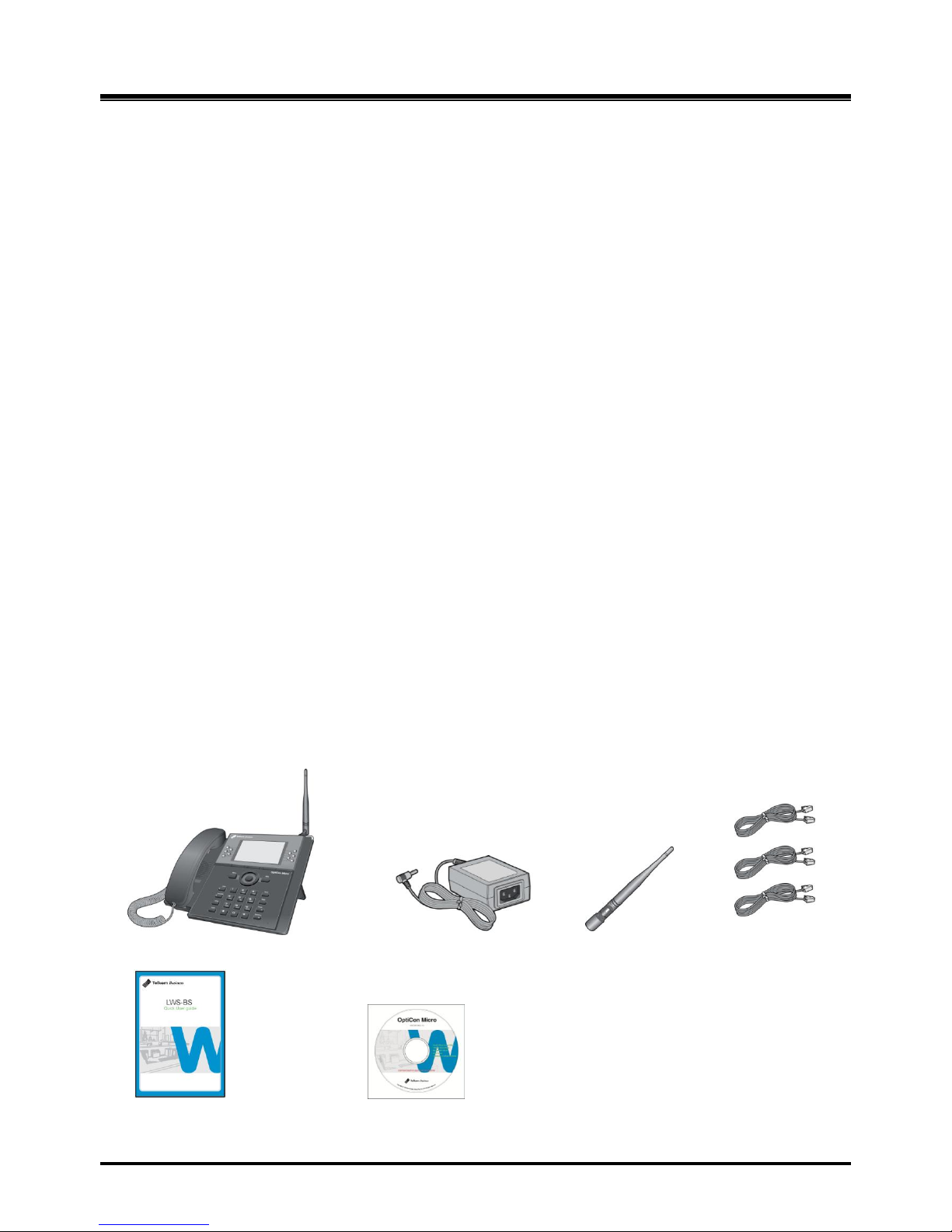
The LWS-BS includes one (1) base station, one (1) AC/DC power adapter, one (1) antenna with rubber
ring, three (3) line cords, one (1) „Quick User Guide‟ and one (1) CD manual. Verify that all parts shown
below are provided in the package.
LWS-BS (LWS-BS unit wit foot) Power Adapter Antenna Line Cord
Quick User Guide CD manual
Figure 1.2-1 LWS-BS Package Contents
Page 9
OptiCon Micro
Installation and Operation Manual
3
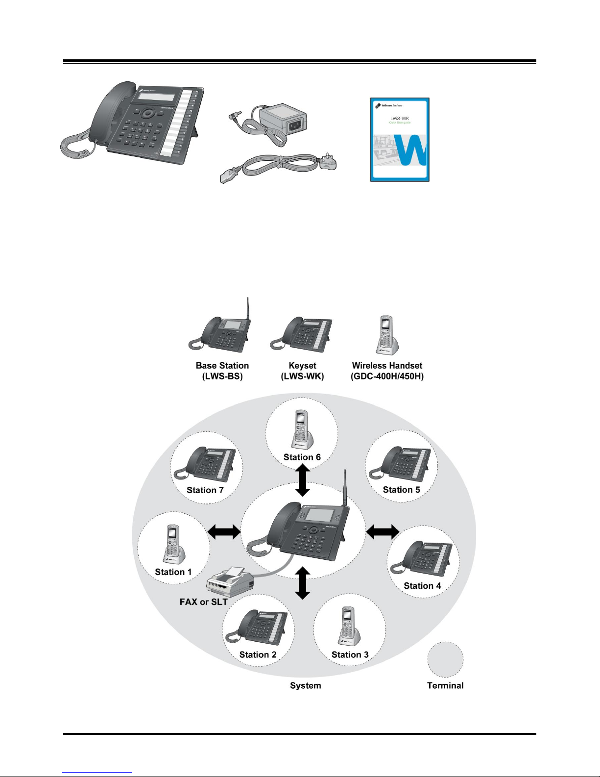
LWS-WK (Wireless terminal) Power Adapter Quick User Guide
AC power cord
Figure 1.2-2 LWS-WK Package Contents
1.3 Configuration
The following image depicts a sample configuration using the LWS-BS system and the wireless
telephone, i.e.: LWS-WK and GDC-400H/450H.
Figure 1. 3-1 Sample Configuration
Page 10

OptiCon Micro
Installation and Operation Manual
4
1.4 System Capability
1.4.1 Description
Lines: up to 3
Cordless Handsets: up to seven cordless handsets (provided separately)
LWS-BS Station 1 Station 2 Station 3 Station 4 Station 5 Station 6 Station 7
Figure 1. 4-1 LWS-BS and
GDC-400H/450H
External calls (Line calls): up to 3 supported.
Figure 1. 4-2 Three (3) External Calls
Supported
Internal Calls: Three (3) internal calls can be conducted on five (5) cordless handsets and the LWS-BS
while the six (6) cordless handset
simultaneously makes an external call.
Figure 1. 4-3 – Internal Calls Supported
One (1) FAX call or SLT can be conducted on the SLT port of the LWS-BS.
Figure 1.4-4 FAX or SLT call via SLT port of the LWS -BS
External call
On line1
External call
On line2
External call
On line3
External call
On line1
External call
On line2
External call
On line3
Or
External call
On line X
Page 11

OptiCon Micro
Installation and Operation Manual
5
1.5 Important Safety Information
Read this information before installing your OptiCon Micro. Failure to comply with these guidelines
could prove either dangerous or illegal. This information helps to avoid personal injury, damage to the
phone, or
other property damage.
1.5.1 Installation and Environment
1. Install the phone according to the manual. Failure to do so could affect product functionality.
2. Do not install phones in direct sunlight so as to ensure full product functionality and fire
prevention.
3. Do not install in non-ventilated areas such as the inside of a desk or other enclosure so as to
ensure full product functionality and fire prevention.
4. Do not install the phone near appliances such as TV, refrigerator, vacuum cleaner, audio
equipment, etc. which may cause interference and affect voice quality.
5. Do not install the phone in an excessively dusty area so as to ensure full product functionality,
fire and electrical short prevention.
1.5.2 Electrical Considerations
1. Do not overload the outlet of power cords so as to prevent fire or electric shock.
2. Do not touch the plug with wet hands. Failure to comply may cause fire or electric shock.
3. To disconnect any phone from the electrical socket grasp and pull the plug, not the cord.
Failure to comply may cause fire or electric shock.
4. Do not place heavy objects on the power cord, or allow the power cord to bend excessively.
Failure to comply may cause fire or electric shock.
5. Only clean power cord and plug when not plugged into the outlet, by rubbing the cord with a soft
cloth. Failure to comply may cause fire or electric shock.
6. Do not modify or disassemble the power cord. If power cord or plug is impaired, do not use it.
Failure to comply may cause fire or electric shock.
1.5.3 Precaution
1. Keep the LWS-BS, LWS-WK and DECT terminals away from
heating appliances
and
electrical noise generating devices such as fluorescent lamps, microwave ovens and
televisions. These noise sources can interfere with the performance of the OptiCon Micro.
2. This system should be kept free of dust, moisture, high temperature (more than 40˚ C) and
vibration, and should not be exposed to direct sunlight.
3. To clean the LWS-BS, LWS-WK and DECT terminals, wipe with a soft cloth only. Do not use
benzene, paint thinner, or an abrasive cleansing powder as these may cause damage to the
system and possible fire or electric shock.
1.5.4 Caution
1. When the product casing is broken, disconnect the power supply cord and arrange to have the
product replaced or repaired.
WARNING
Replace batteries only with the same or equivalent type recommended by the
manufacturer. Dispose of used batteries according to the manufacturer’s instructions
Page 12

OptiCon Micro
Installation and Operation Manual
6
2. INSTALLATION
2.1 Pre-Installation
Please read the following guidelines concerning installation and connection before installing the OptiCon
Micro. Be sure to comply with any applicable local regulations.
2.1.1 Safety Installation Instructions
When installing telephone wiring, basic safety precautions should always be followed to
reduce the risk of fire, electric shoc k and personal injury:
1. Never install telephone wiring during a lightning storm.
2. Never install a telephone jack in wet locations unless the jack is specifically designed for a
wet environment.
3. Never touch un-insulated telephone wires or terminals unless the telephone line has been
disconnected.
2.1.2 Wiring Precautions
Be sure to follow these precautions when wiring:
1. Do not wire telephone cable in parallel with AC cabling, such as power to a computer, fax
machine, etc. If the cable is placed near those wires, shield the cable with metal tubing or use
shielded cable and ground the shield.
2. Use a protector to prevent the cables from being stepped on if cables are placed on the floor.
Avoid placing wiring under carpets.
3. Avoid using the power supply outlet for the OptiCon Micro with computers, fax machine, and
other office equipment to prevent induction noise interruption.
4. Make sure that power switch is OFF during wiring. After wiring is completed, the power
adapter may be turned ON.
5. Make sure that the wiring is correct so as to ensure full product functionality.
2.2 DECT Installation
2.2.1 Introduction
The OptiCon Micro is equipped with a DCTU (Digital Cordless Telephone Unit) which support DECT
installation. DECT Terminals are subscribed and registered.
The DCTU can support up to 7 wireless terminals.
The following equipment is required to connect the wireless system:
LWS-BS DCTU
LWS-BS should be installed indoors and protected from surge because it is designed for
indoor station.
LWS-BS‟s DCTU supports 6 simultaneous calls (6 traffic channels).
Page 13
OptiCon Micro
Installation and Operation Manual
7
Wireless Terminal (GDC-400H, 450H,LWS-WK)
DCTU Specifications
Item
Specification
Transmission Max Power
250mW
Access Method/Duplex
TDMA/TDD
Frequency Band
1,880 ~ 1,900MHz
Channel Spacing
1.728MHz
Modulation
GFSK
Data rate
1.152Mbps
Wireless Terminal Specifications
Item
Specification
Max. Transmission Power
250mW
Modulation Method
GFSK
Frequency Band
1,880MHz ~ 1,900MHz
2.2.2 Cell Coverage
In a typical office environment where there are some obstacles, the coverage area of the LWS-BS cell is
approximately 15 ~ 30 meters. A better coverage distance could be achieved in more open areas. The
coverage area is however, truly dependent on the office environment characteristics (e.g. construction
material of walls, metallic objects, doors, windows, stair-wells, etc). Other radio equipment such as
DECT phones or WIFI equipment could also affect the coverage area. The coverage area will be unique
for each office environment.
2.2.3 General Guidelines
1. Try to locate the LWS-BS in such a way to maximise the direct line of sight between the wireless
terminals and the LWS-BS antenna.
2. Try to minimize obstructions near the antenna of LWS-BS.
3. Where possible, centralize the LWS-BS within the desired coverage area that you intend to cover.
4. In an office environment, consider the office furniture in order to minimize reflection, diffraction and
scattering of the DECT radio waves when you choose the position of the LWS-BS.
5. Try not to locate the LWS-BS on top of any steel furniture.
6. Electronic equipment such as a copy machine, a printer or a computer might have an influence on
the coverage area.
7. Try to locate the LWS-BS in an open area. Avoid areas such as high traffic areas, corners and
narrow walkways.
8. When moving around while busy on a wireless handset, you may experience degradation in
speech quality (e.g. breaking up of speech). If this happens, rather stand still during the call.
Page 14
OptiCon Micro
Installation and Operation Manual
8
2.3 Battery Installation
2.3.1 GDC-400H Handset Battery Installation
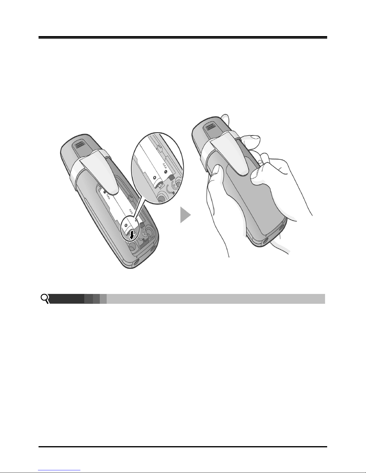
To install a Battery in the GDC-400H DECT handset:
1. Remove the battery cover by pressing the latch as shown, and slide down to open.
2. Verify batteries are orientated correctly for polarity when inserting.
3. Close the battery cover and slide it upward until it clicks into place.
Figure 2. 3.1-1 Handset Battery Installation
NOTE:
Purchase new batteries from your Telkom Service Centre.
The battery has limited operating life (warranty period for the battery is 6 months
from purchasing date).
Page 15
OptiCon Micro
Installation and Operation Manual
9
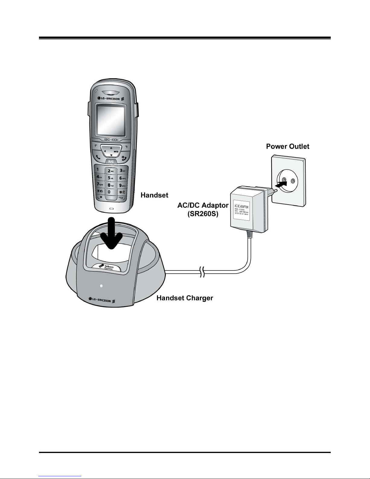
2.3.1.1 GDC-400H Battery Charging
To charge the handset:
1. Place handset in the plugged-in charger for 12 hours before initial use.
Figure 2. 3.1.1-1 GDC-400H Handset Battery Charging
Page 16
OptiCon Micro
Installation and Operation Manual
10
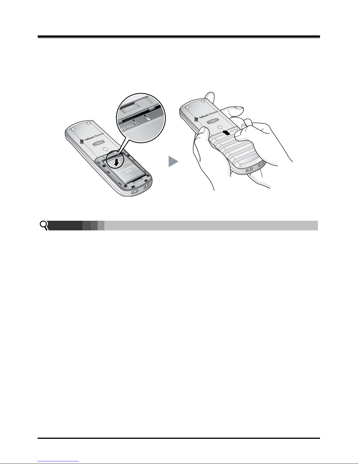
2.3.2 GDC-450H Handset Battery Installation
To install a Battery to the GDC-450 DECT handset:
1. Remove the battery cover by pressing the latch as shown, and slide down to open.
2. Verify batteries are orientated correctly for polarity when inserting.
3. Close the battery cover and slide it upward until it clicks into place.
Figure 2. 3.2-1 GDC-450H Handset Battery Installation
NOTE:
Purchase new batteries from your Telkom Service Centre.
The battery has limited operating life (warranty period for the battery is 6 months
from purchasing date).
Page 17
OptiCon Micro
Installation and Operation Manual
11
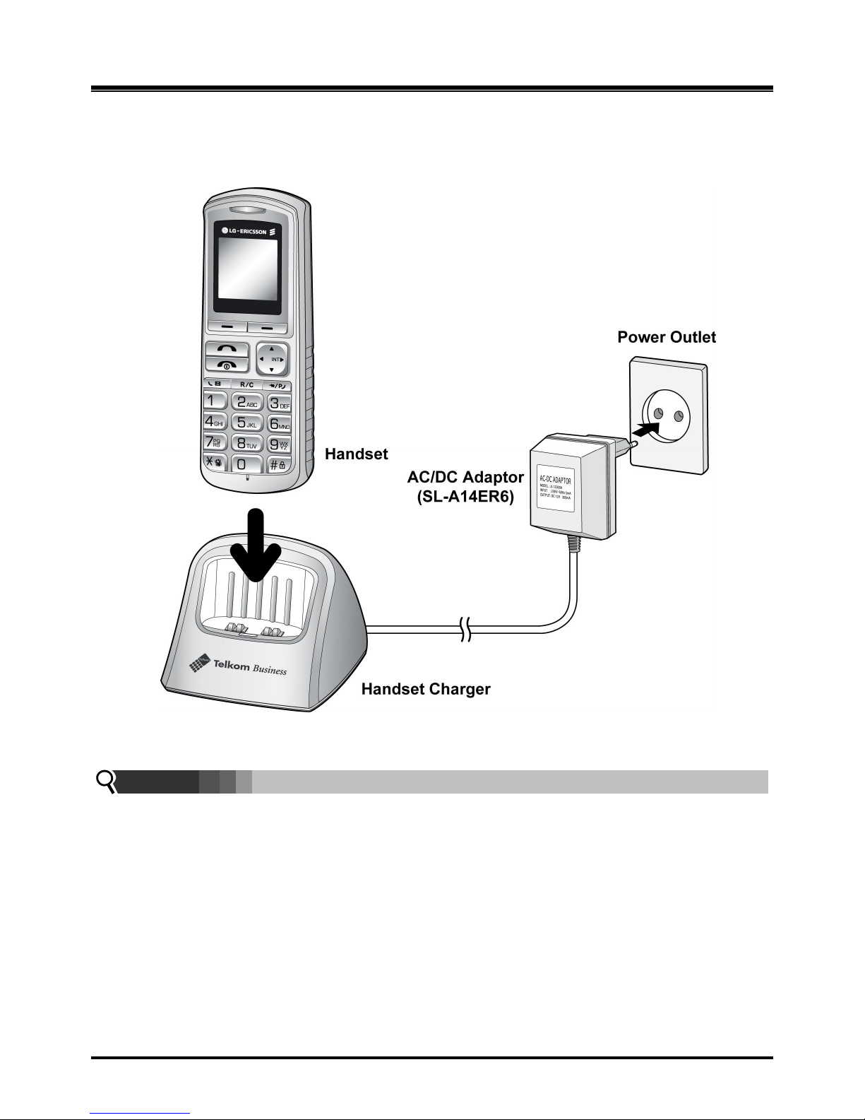
2.3.2.1 GDC-450H Battery Charging
To charge the handset:
1. Place handset on the plugged-in charger for 12 hours before initial use.
Figure 2. 3.2.1-1 GDC-450H Handset Battery Charging
NOTE:
The GDC-450H uses an advanced battery charging technology, the battery level is
checked every 6 hours causing the red recharge light to illuminate briefly.
2.4 LWS-BS, Handset and Peripheral Connections
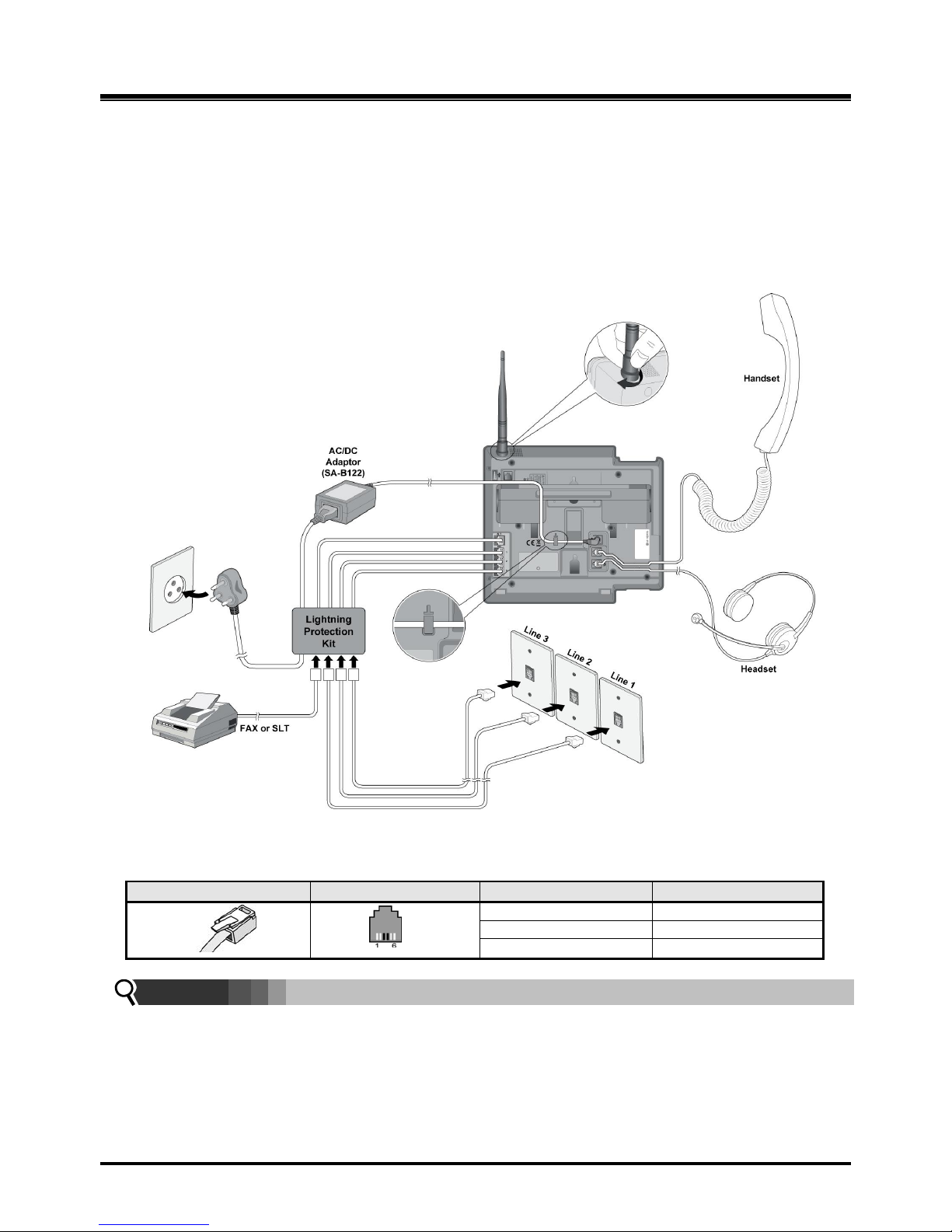
To connect the LWS-BS with phone lines and its peripherals (Refer to figure 2.3.1):
1. Connect the line cord of the lightning protection unit to the AC/DC Adaptor of the LWS-BS
and the DC connector of the AC/DC Adaptor to the bottom of base station.
2. Connect the 3 pin plug of the Lightning Protection Kit to the AC socket.
3. Connect the 3 line cords and the FAX/SLT line cord of the Lightning Protection Kit to the Line and
FAX/SLT sockets on the bottom of the LWS-BS.
4. Connect the Telkom exchange line wall sockets to the Line sockets of the Lightning Protection Kit
Page 18
OptiCon Micro
Installation and Operation Manual
12
using the line cords provided. Connect the FAX machine (or SLT phone) line cord to the
FAX/SLT socket on the Lightning Protection Kit.
5. Connect the handset curly cord to the handset jack on the bottom of the LWS-BS.
6. Connect the Headset to the headphone jack on the bottom of the LWS-BS. (Optional)
7. Screw the included rubber antenna clockwise onto the terminal at right side of the top of the
LWS-BS.
8. The USB (host) port on the bottom of the LWS-BS is provided for upgr ading SW and system
configuration.
Figure 2. 4.1 LWS-BS Connections
Connector
Pin Number
NO
Signal Name
RJ11
1,2
N/A
5,6
N/A
NOTE:
Use only the included LG-Ericsson AC Adapter (SA-B122).
Using a headset with the LWS-BS is optional.
Avoid mounting near TV, another cordless telephone or microwave oven.
Page 19
OptiCon Micro
Installation and Operation Manual
13
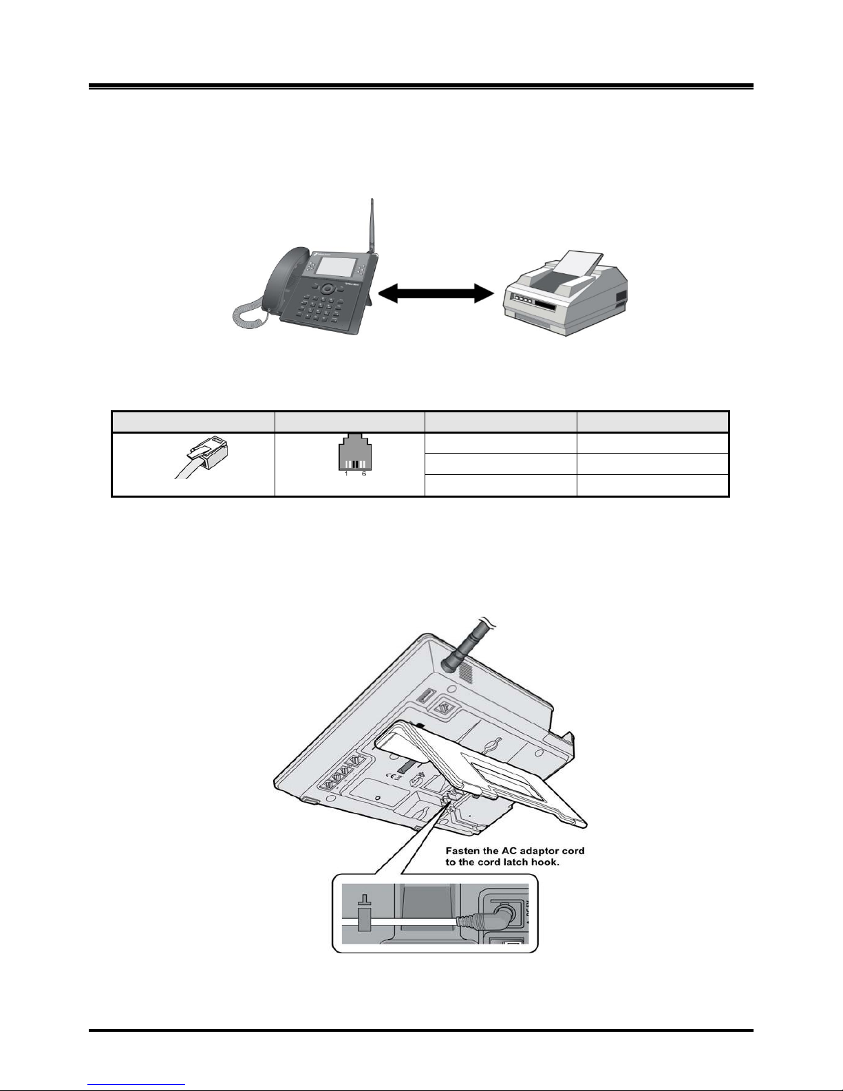
2.4.1 FAX Connection
The following figure illustrates how to connect a FAX to the LWS-BS. Please make sure that the Fax
line cord is connected to the Lightning protection Kit and the other side of the Lightning Protection
Kit to the LWS-BS.
Figure 2. 4.1-1 LWS -BS and FAX
Connection
Pin Assignment
Connector
Pin Number
NO
Signal Name
RJ11
1,2
N/A
3,4
TIP, RING
5,6
N/A
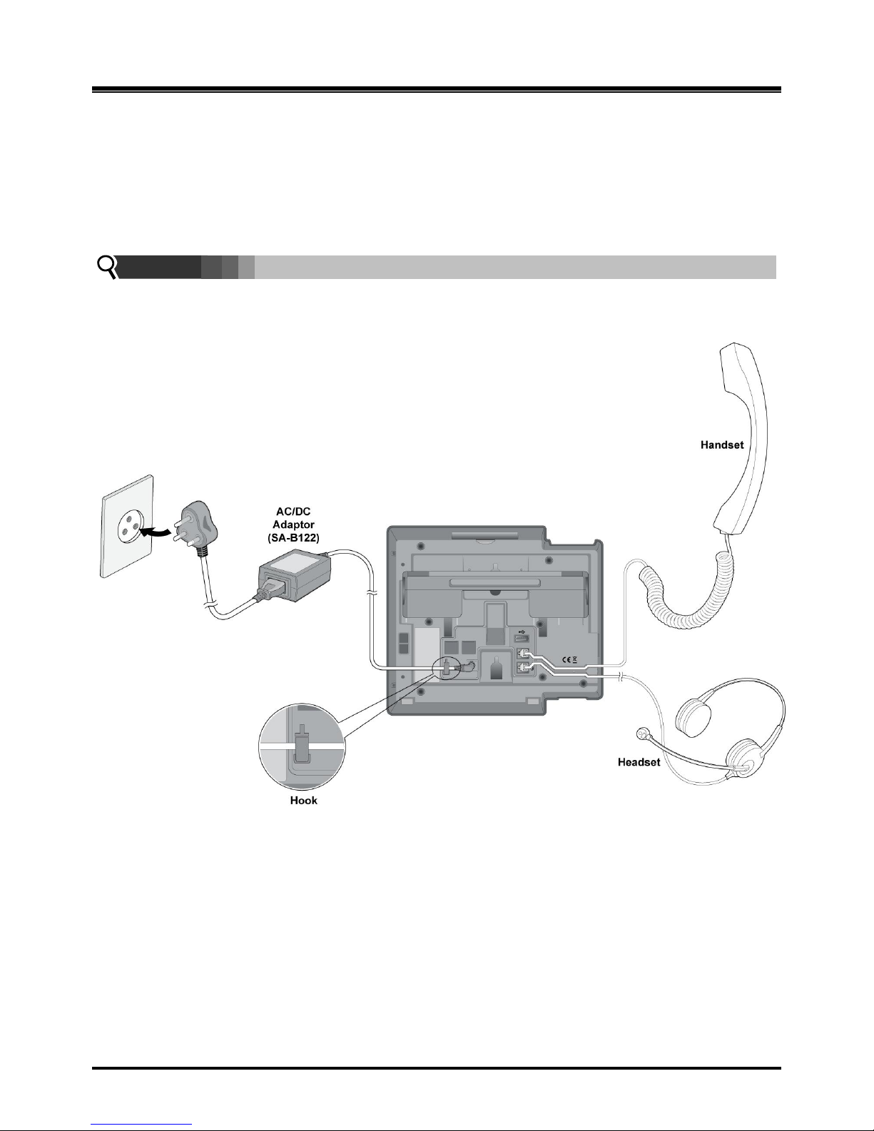
2.4.2 AC/DC Adapter Connection
To connect the AC/DC adapter:
1. Plug the DC outlet of the AC/DC Adapter cord into the jack on the LWS-BS.
2. Fasten the AC/DC Adapter cord to the latch hook as shown (inset
detail).
Figure 2. 4.2-1 AC/DC Adapter
Connection
Page 20
OptiCon Micro
Installation and Operation Manual
14
2.4.3 LWS-WK Connection
To connect the LWS-WK to be used with the LWS-BS:
1. Plug the DC outlet of the AC/DC Adapter cord into the jack on the LWS-WK.
2. Fasten the AC/DC Adapter cord to the latch hook as shown (inset detail).
3. Connect the handset curly cord to the handset jack on the bottom of the LWS-WK.
4. Connect the headset to the headset jack on th e bottom of the LWS-WK. (Optional)
NOTE:
Use only the included LG-Ericsson AC Adapter (SA-B122).
Using a headset with the LWS-WK is optional.
Avoid mounting near TV, another cordless telephone or microwave oven.
Figure 2. 4.3-1 LWS -WK Connection
Page 21
OptiCon Micro
Installation and Operation Manual
15
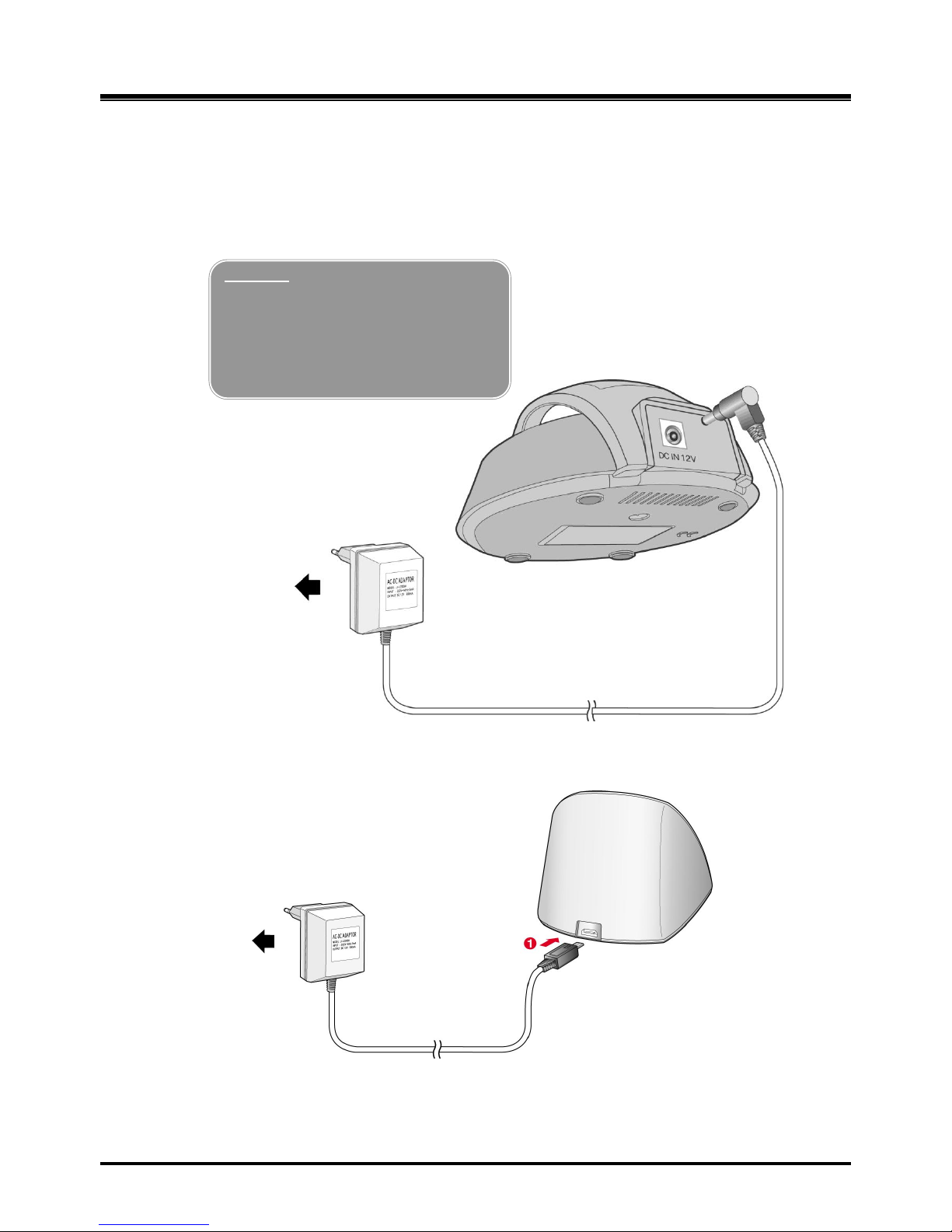
2.4.4 Wireless Handset Connection
To connect a Wireless Handset to be used with the system:
1. Plug in the AC adapter cord to the Handset Charger and plug AC outlet to the power outlet.
2. Use only the included LG-Ericsson AC/DC adapter, which is provided together with GDC400H/450H.
Figure 2.4.4-1 Wireless Handset Charger Connection: GDC-400H
Figure 2.3.4-2 Wireless Handset Charger Connection: GDC-450H
Warning
Use only the main power adapter
supplied. Any other adapter could
damage your GDC-400H and invalid
ate your warranty
2. To AC OUTLET
1. Adaptor
Page 22
OptiCon Micro
Installation and Operation Manual
16
2.4.5 Foot Stand Connection (the LWS-BS and LWS-WK)
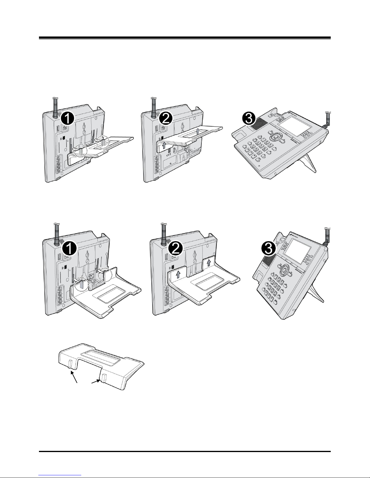
When the Foot Stand of either the LWS-BS or the LWS-WK is attached, the angle of the phone can
be adjusted to 35 or 55 degrees.
To install the Foot Stand for a 35-degree angle, perform the following:
Figure 2. 4.5-1 Foot Stand Connection (35-degree angle)
To install the Foot Stand for a 55 degree-angle, perform the following:
Figure 2. 4.5-2 Foot Stand Connection (55-degree angle)
1. Align the top tabs on the foot stand with the slots on the back of the LWS-BS or the LWS-WK.
2. Move the foot stand upward until it clicks into place.
Top tap
Page 23
OptiCon Micro
Installation and Operation Manual
17
2.5 Hardware Installation
2.5.1 Wall Mounting of the LWS-BS or the LWS-WK
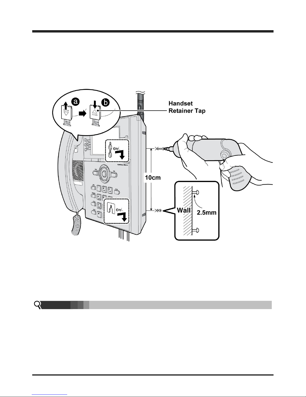
To wall mount the LWS-BS or LWS-WK, perform the following:
1. Remove the foot stand.
2. Make sure the handset retainer tab is positioned at „b‟ as shown below figure.
Figure 2. 5.1-1 Wall Mount of LWS-BS/ LWS-WK
3. Make a sma ll mark on the wall where you want the top keyhole slot to align and install a screw
(not provided) so that it protrudes slightly, approx. 2.5mm, from the wall (Figure shown).
4. Measure a straight line down 10cm from the mark, and install another screw (not provided).
5. Align the keyholes on the bac k of the phone with the screws in the wall, and then slide the phone
down on the screws to secure the phone.
Note:
Ensure all cables are properly routed and that power is installed before affixing to the wall
mount screws.
Page 24
OptiCon Micro
Installation and Operation Manual
18
2.6 Component Description
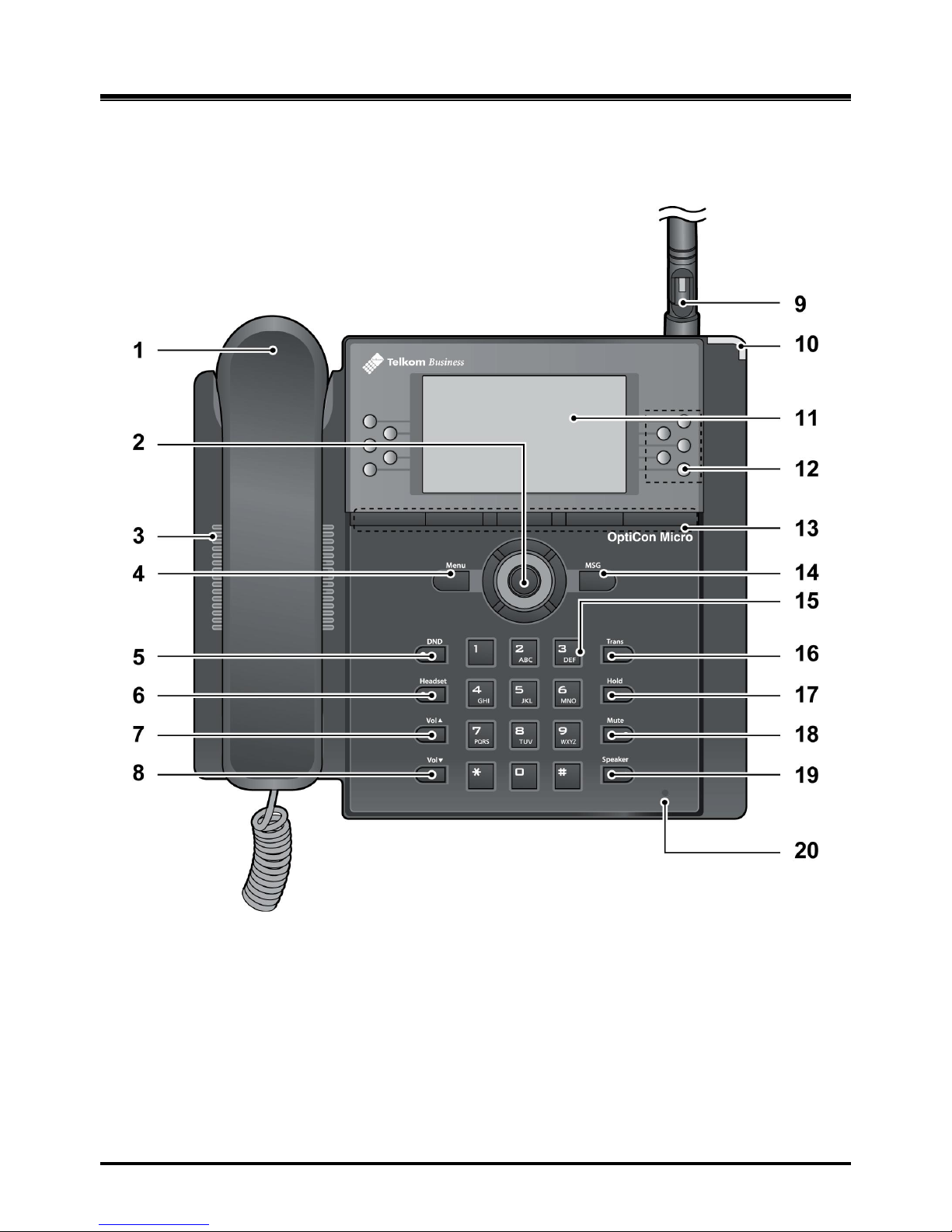
2.6.1 LWS-BS Description
1. Handset 2. Navigation/OK Key
3. Speaker 4. Menu Button
5. DND Button 6. Headset Button
7. Volume Up Button 8. Volume Down Button
9. Antenna 10. Ring Indication
11. LCD 12. Line/Station Selection Buttons
13. Soft Buttons 14. MSG Button
15. Dial Buttons 16. Trans Button
17. Hold Button 18. Mute Button
19. Speaker Button 20. Microphone
Figure 2. 6.1-1 LWS -BS Component
Description
Page 25
OptiCon Micro
Installation and Operation Manual
19
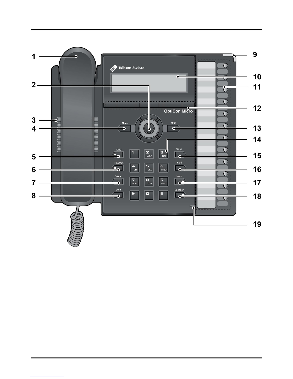
2.6.2 LWS-WK Description
1. Handset 2. Navigation/OK Key
3. Speaker 4. Menu Button
5. DND Button 6. Headset Button
7. Volume Up Button 8. Volume Down Button
9. Ring Indication 10. LCD
11. Line/Station Selection Buttons 12. Soft Buttons
13. MSG Button 14. Dial Buttons
15. Trans Button 16. Hold Button
17. Mute Button 18. Speaker Button
19. Microphone
Figure 2. 6.2-1 LWS -WK Component
Description
Page 26
OptiCon Micro
Installation and Operation Manual
20
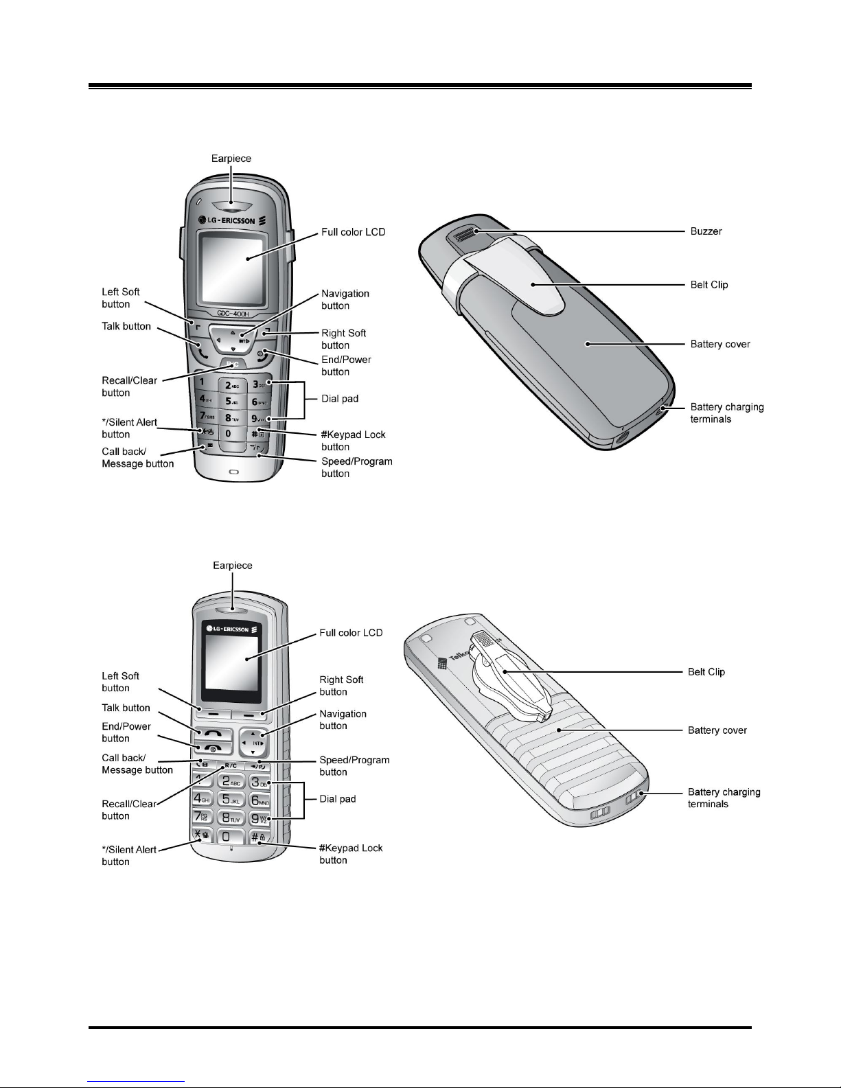
2.6.3 Wireless DECT Handset Description
Figure 2. 6.3-1 GDC-400H Component Description
Figure 2. 6.3-2 GDC-450H Component Description
Page 27

OptiCon Micro
Installation and Operation Manual
21
2.7 Hardware Initialization
2.7.1 LWS-BS and LWS-WK
Once the LWS-BS and the LWS-WK have been properly installed in the desired location, perform
the following:
1. Plug in the AC/DC adapter to the LWS-BS or the LWS-WK (use only the included AC/DC
adapter, SA-B122).
2. The LWS-BS or the LWS-WK is powered up and its display on the LCD will be activated.
3. Register the LWS-WK to the LWS-BS, see section 2.12.
Note: The LWS-BS requires one minute to become fully functional after power on.
2.7.2 Wireless Handset
To start up the Handset:
1. Press and hold [ ] for approximately 2 seconds.
2. The handset automatically enters standby mode when a signal is located.
3. The handset automatically returns to standby mode whenever it is placed on the charger.
4. Register the Wireless Handset to the LWS-BS, see section 2.12.
To power-down the Handset:
1. Press and hold [ ] for approximately 3 seconds
2.8 Display
2.8.1 LCD Specification
Users can select one of the backlight control options (always on, always off, on when busy).
2.8.1.1 LWS-BS
240 x 144 Graphic LCD
Backlit On/Off Control with 3 selectable option
Ten-Level Contrast Setting
2.8.1.2 LWS-WK
240 x 42 Graphic LCD
Backlight On/Off Control
Ten-Level Contrast Setting
Page 28
OptiCon Micro
Installation and Operation Manual
22
2.8.2 LCD Display
2.8.2.1 LWS-BS
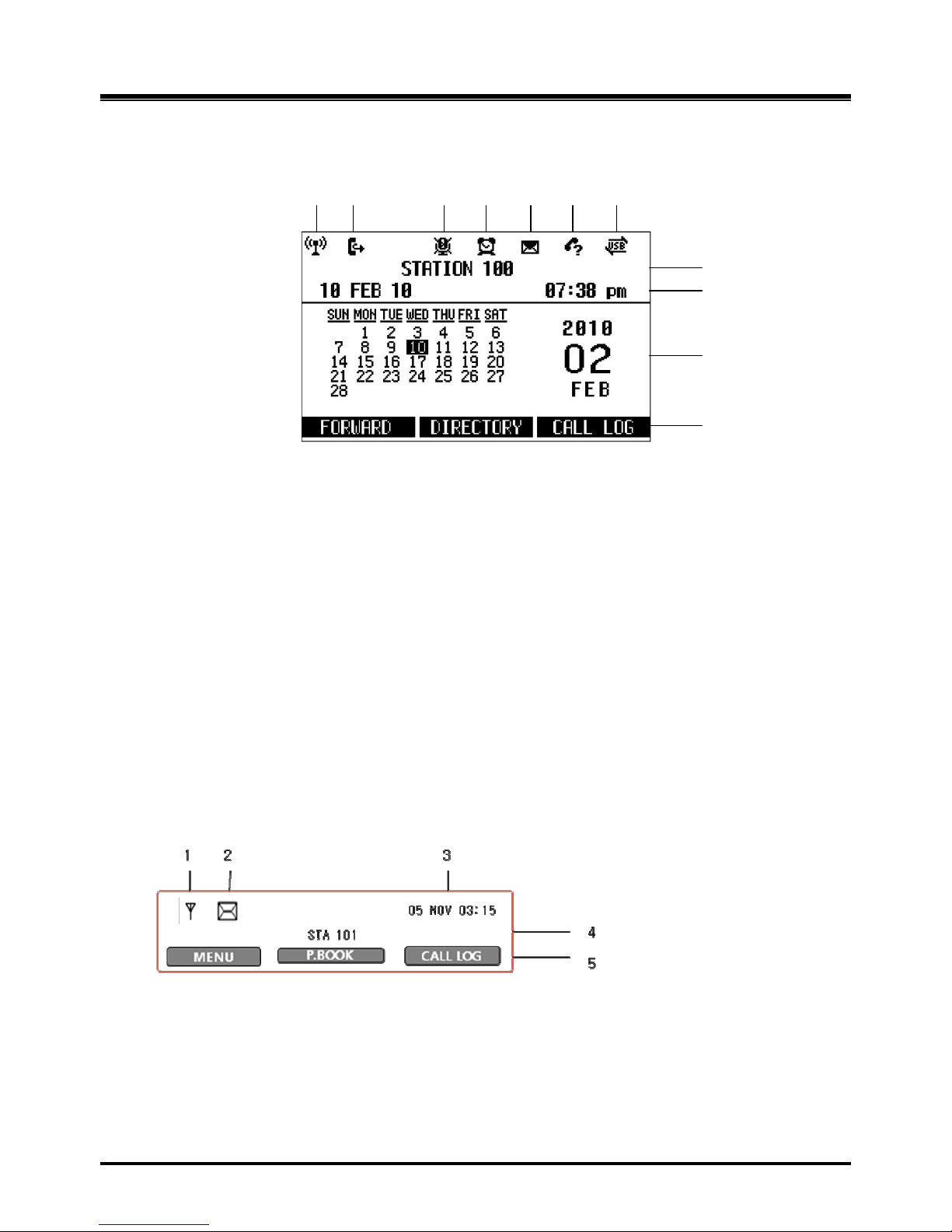
Figure 2.8.2.1-1 LWS-BS LCD Display Screen
1. Antenna – LCD displays when DCTU of LWS-BS works and it can be linked to DECT.
2. Call Forward – Icon indicates the base station is currently set for call forwarding.
3. Mute – Icon indicates if the mu te button is activated for blocking voice transmission from your
phone during a conversion.
4. Alarm – Icon indicates the alarm has been set.
5. Message – Icon indicates there is at least one new message.
6. Missed call – Icon indicates that there are missed calls in your absence.
7. USB – Icon indicates a USB memory device is inserted.
8. Station Number – Displayed in idle state. If th e LWS-BS station has a name assigned, the
name is displayed.
9. Date & Time – Displayed in idle state.
10. Calendar – Displayed in idle state.
11. Soft Menu – Dependent on the status and menu choices, the current available selections
are displayed.
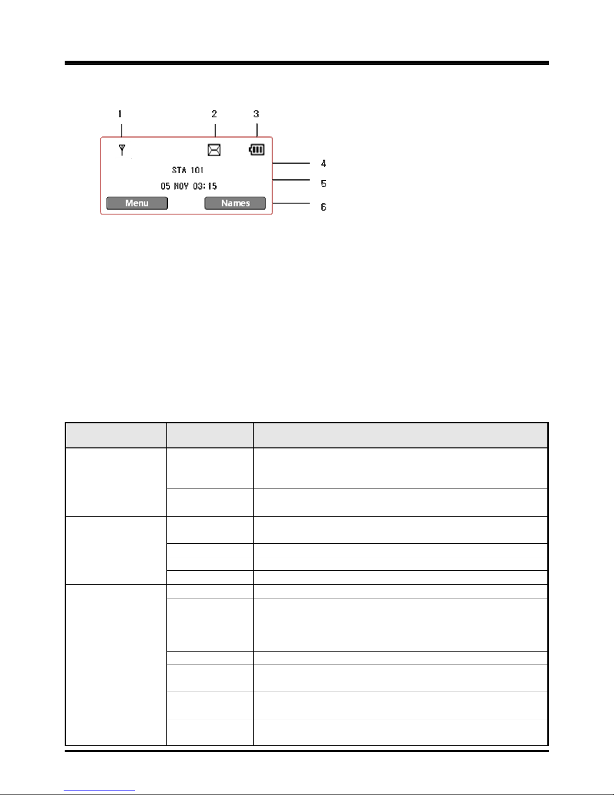
2.8.2.2 LWS-WK
1. Antenna – Displayed when the LWS-WK is in the range of a LWS-BS where it can be linked.
The icon disappears when it moves out of range. The closer it moves to the base, the
stronger RSSI will be.
2. Message – Icon indicates there is at least one new message.
3. Date & Time –Displayed in idle state.
4. Station Number – Displayed in idle state.
5. Soft Menu – Dependent on the status and menu choices, the current available functions
are displayed.
1 2 3 4 5 6 7 8 9
10
11
Page 29
OptiCon Micro
Installation and Operation Manual
23
2.8.2.3 GDC-400H and GDC-450H Wireless Handset
1. Antenna – Displayed when the handset is in the range of a LWS-BS where it can be linked.
The antenna icon disappears when it moves out of range. The closer it moves to the base,
the stronger RSSI will be.
2. Message – Icon indicates there is at least one new message.
3. Date & Time – Displayed in idle state.
4. Battery – Displays battery level when a handset is operating.
5. Handy Number – Displayed in idle state.
6. Soft Menu – Dependent on the status and menu choices, the current available functions
are displayed.
2.9 Keypad Description
2.9.1 LWS-BS
FUNCTIONAL
BUTTON NAME
BUTTON DESCRIPTION
Flex Key
Line selection
button
Line 1 ~ 3
Access an idle line for making an external call or answer the
incoming call by pressing the line button.
Station button
Station 101~107
Allow to make an intercom call.
Station 101~107 : Wireless Terminals
Soft Menu Key
Soft key 1,2,3
Dependent on the status and menu choices, the current
available functions are displayed.
Menu
Main Menu
MSG
Retrieve Messages
Navigation button
Up/down/right/left/ok
Function Key
DND
Setting Night/Weekend mode
Headset
Headset mode or speakerphone mode is switched by turns
whenever it is pressed.
[Headset] button in idle state. Headset LED will be
illuminated when headset mode is selected.
Vol. up
Volume up during a call, LCD contrast is up in idle state.
Vol. down
Volume down during a call, LCD contrast is down in idle
state.
Trans
An intercom call or the line call can be transferred to
another station or line during a conversation.
Hold
When on a call, the station user can place an active call on
hold; the held party will hear a hold tone.
Page 30
OptiCon Micro
Installation and Operation Manual
24
Mute
During a conversation, pressing the [MUTE] button to disable
the handset microphone or the speakerphone while continuing
to listen to the other. Pressing the [MUTE] button again, will
reactivate the microphone. This button is active on all calls.
Speaker
Pushing the [Speaker] button allows the user to continue a call
using the speaker for two-way communication.
Pressing the [Speaker] button again, will terminate the call. Exit
on Menu
Dial Pad
0~9, *, #
Use to dial a number, select a menu item, or input values.
2.9.2 LWS-WK
FUNCTIONAL
CLASSIFICATION
BUTTON NAME
BUTTON DESCRIPTION
Flex Key
Line selection button
Line 1 ~ 3
Access an idle Line for making an external call or
answer the incoming call by pressing Line button.
Station button
Station 100~108
Allows making an intercom
call. Station 100 : LWSBS
Station 101~107 : Wireless Terminals
Station 108 : SLT/FAX
Soft Menu Key
Soft key 1,2,3
Dependent on the status and menu choices, the
current available functions are displayed.
Menu
Main Menu
MSG
Retrieve Messages
Navigation button
Up/down/right/left/ok
MSG
Retrieve Messages
Navigation button
Up/down/right/left/ok
Function Key
DND
Blocks incoming outside line ringing, intercom calls
and transfers
Headset
Connecting an optional headset to the base station
allows hands-free conversations by pressing
[Headset] button.
An industry standard headset can be connected to a
station
Vol. up
Volume up
Vol. down
Volume down
Trans
An intercom call or a line call can be transferred to
another station or line during a conversation.
Hold
When on a call, the station user can place an active call
on hold; the held party will hear a hold tone.
Mute
During a conversation, pressing the [MUTE] button to
disable the handset microphone or the speakerphone
while continuing to listen to th e other. Pressing the
[MUTE] button again, will reactivate the microphone.
This button is active on all calls.
Dial Pad
0~9, *, #
Use to dial a number, select a menu item, or input
values.
Page 31
OptiCon Micro
Installation and Operation Manual
25
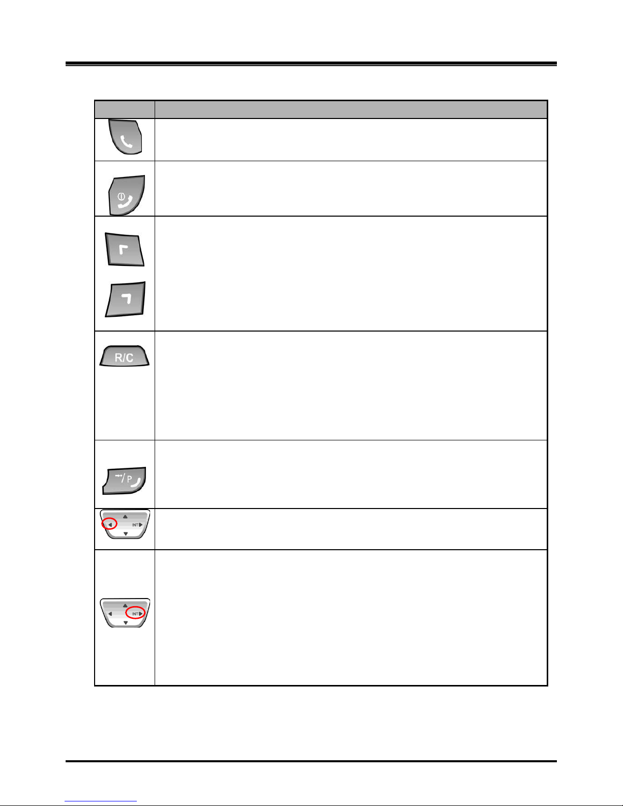
2.9.3 GDC-400H/450H Wireless Handset
Button
Function
[TALK]
Try to make a call
Redial number saved in handset.
[END/POWER]
Pressing longer than 1 second : Power Off
Pressing shorter than 1 second :Leave a call back or a message
Pressing shorter than 1 second during incoming: Ignore a call.
[LEFT SOFT / RIGHT SOFT]
You can access to the current functions by pressing the soft button directly below
the function display.
[FLASH/CLEAR]
Talking Mode : Register recall
Flash a call and retry next call
When using pre-dial :
Pressing longer than 1 second : All digits are cleared
Pressing shorter than 1 second : 1 digit backspace
When using local functional operation : Function cancel
(It should be pressed longer than 1 second)
[SPEED/PROGRAM]
Post-Dial :
Pressing shorter than 1 second: System speed dial (SPEED).
Pressing longer than 1 second: Start/Finish a system program
(PROGRAM). Same as the FUNCTION button of GDC-345H.
[LEFT]
In an idle state : To view missed call
In MENU : LEFT
[RIGHT/INTERNAL/TRANSFER/HOLD]
Talking Mode :
Pressing shorter than 1 second: Transfer a call to the other
station(TRANS).
Pressing longer than 1 second: Hold a call / release a holding call (HOLD).
In an idle state :
In MENU : right button
Home Wireless Terminal : Internal call
Key-telephone Wireless Terminal : Trying to make a intercom call or a line
call
Page 32
OptiCon Micro
Installation and Operation Manual
26
Button
Function
[CALL BACK]
Pressing shorter than 1 second : Leave a call back or a message
[UP/DOWN]
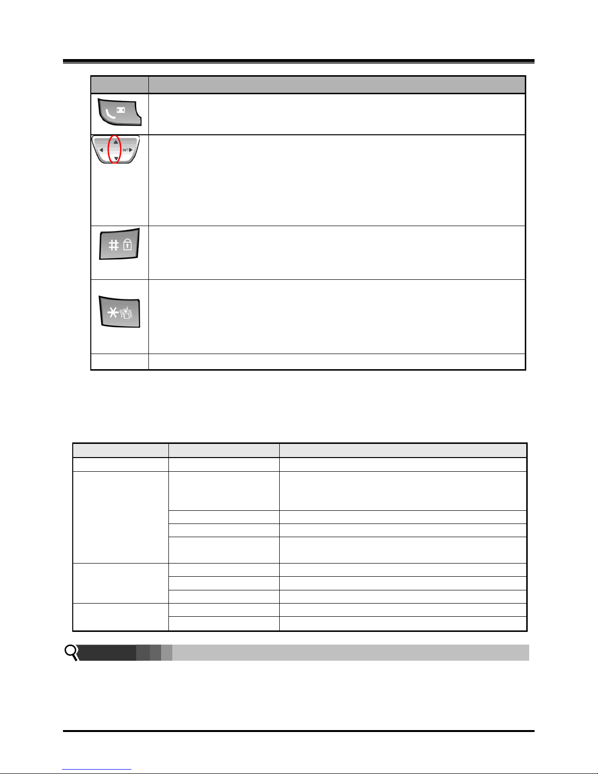
Talking Mode : Increase/decrease received audio volume, Call by name, CLIP
Standby Mode :
In Menu: Navigate and select among function items in a menu or submenu.
Idle state :
UP : Local Redial
DO WN : Phonebook list
To lock Keypad (Pressing longer than 1 second)
„#‟ Display (Pressing shorter than 1 second)
While Dialing: To insert pause (Pressing longer than 1 second)
Talking Mode (Only when the Camp-On function is supported by ipLDK
series) : Camp-On
Standby Mode :
„*‟ is displayed (Pressing shorter than 1 second)
Enable/disable manner mode(Pressing longer than 1 second)
0~9
- Standard dial button
2.10 LED Operation Description
2.10.1 LWS-BS and Wireless Keyset
FUNCTION
LED OPERATION
LED DESCRIPTION
Ring Indicator
RED Blink
Indicates incoming ring signal.
Line Selection
Button
Green/RED Blink
Line is in hold state.
Green blink: Line is held by the own station. Red
blink: Line is held by others.
Orange Blink
Indicates ringing state
Green steady on
The gre en LED illuminates when you are on a call.
Red steady on
The red LED indicates that the associated line is in
use by other user.
Station Selection
Button
ON (RED)
Illuminates when you or others are on a call.
Red Blink
Ringing state indication
OFF
Idle State
DND, Headset
Mute, Speaker
ON
Illuminates when each function is activated.
OFF
Function is deactivated.
Note:
Blinking rate:
Base Station: 0.5/sec,
Wireless Keyset: 0.78/sec
Page 33

OptiCon Micro
Installation and Operation Manual
27
2.11 Configuration
2.11.1 Nation code
To set the nation code on the LWS-BS, per form the following:
1. Press the [Menu] button on the LWS-BS.
2. Select 1. CONFIGURATION > 2. COUNTRY.
3. If you want to change the country, press the [CHANGE] soft key or the [OK] Navigation key.
4. Set the Nation code. *27 for Telkom.
5. When finished, press the [SAVE] button, and system will ask you to confirm it.
6. If you select [YES] by pressing digit 1, the system will restart and the database will be initialized.
2.11.2 LWS-BS Date and Time
The Date and Time of the LWS-BS can be set and adjusted by the user after configuring the Location
(Nation code set, recommended). In the event of a power failure, the system will retain Date and Time
stored in database with internal Lithium Battery. All terminals registered to the LWS-BS will
automatically take the Date and Time information of the LWS-BS after pressing Talk key or Speaker
button.
To set the Date & Time:
1. With the LWS-BS in idle state, press the [Menu] button.
2. Select 1. CONFIGURATION > 1. DATE / TIME.
3. In this me nu, set the Date and Time by entering the desired values using the keypad and
scrolling with the navigation arrow keys.
4. When finished, press the [SAVE] soft key or press th e [OK] Navigation key and a
confirmation tone will be heard.
Note:
Date and Time of Wireless KTU will be updated by the LWS-BS after pressing Talk key or
Speaker button.
2.11.3 GDC-400H/450H Handset Time
To set the GDC-400H/450H Wireless Handset Time:
1. Press [MENU].
2. Select [Phone Settings] > [Clock].
3. Enter the [DD.MM.YY] and hours and minutes using 4 digits (ex., 0 7 3 5 for 07:35).
Note:
Date and Time of GDC-400H/450H and Wireless KTU will be updated by the LWS-BS
after pressing Talk key (GDC-400H/450H) / pressing speaker button (Wireless KTU).
Page 34

OptiCon Micro
Installation and Operation Manual
28
2.12 Terminal Registration and Termination
The LWS-BS controls the functional service and registration of the LWS-WK and GDC-400H/450H. First
of all, they should be subscribed to LWS-BS before used.
2.12.1 Subscribing the GDC-400/450H / LWS-WK to LWS-BS
Only one Wireless Handset or Keyset can be registered at a time.
2.12.1.1 Enabling Subscriptions
To enable registration of terminal the below procedure should be performed on the LWS-BS.
1. Press t he [Menu] button.
2. Press [Digit 1] (CONFIGURATION submenu), or
Select [1. CONFIGURATION] using the Navigation up/down key and then press t h e[OK]
soft button or Navigation „OK‟ key.
3. Press [Digit 4] (STATION REGISTER submenu), or Select [4. STATION REGISTER] using
the Navigation up/down key and then press the[OK] soft button or „OK‟ key of the
Navigati on.
4. Press [Digit 1] (REGISTER submenu), or Select [1. REGISTER] using the Navigation
up/down key and then press [OK] soft button or Navigation „OK‟ key.
5. Select the phone type using the Navigation left/right key (GDC-4XX or LWS-WK)
6. Press th e [OK] soft button or Navigation „OK‟ key.
7. Wait for completing the subscription.
8. When the subscription is completed, the below message is shown on the LCD of the
LWS- BS.
STATION: 10X
SUBSCRIBED: SUCCESS
2.12.1.2 Subscribing GDC-400H/450H to the LWS-BS
To subscribe to the LWS-BS, below procedure shoul d be performed on the GDC-400H/450H.
1. Press [Menu] ( , ) button to display the menu.
2. Highlight [Phone Register] the me nu using the Navigation ( ) button.
3. Press [OK] ( , ) button; and then the Phone Register menu will display.
4. Select [LWS Subscription] using the up and down arrows of the Navigation ( )
button and press [OK] ( , ) button.
5. Display [Searching.1].
6. The system [RFPI (PARK): e.g. 01234567890123] will display when a system is found.
The RFPI (PARK) of your system is available from your System Administrator or the
attendant.
7. Press [OK] ( , ) button; in a few second, a confirmation tone will be heard at the
GDC-400H/450H.
8. If the subscription fails, repeat the procedure from Step 1 to 7 at the LWS-BS and Step 1 to 7 from
the GDC-400H/450H.
Page 35

OptiCon Micro
Installation and Operation Manual
29
Note:
: [Menu], [OK] button on GDC-400H
: [Menu], [OK] button on GDC-450H
RFPI : Radio Fixed Part Identity
Seven Wireless Handsets and/or Keysets can be registered to one LWS-BS.
2.12.1.3 Subscribing LWS-WK to the LWS-BS
To subscribe to the LWS-BS, below procedure is performed on the LWS-WK.
1. Press the [Menu] button to display the menu.
2. Highlight [Phone Register] using the Navigation up/down key, and then press the [OK] soft
button or Navigation „OK‟ key.
3. Select [Subscription] using the Navigation up/down key, and then press [OK] soft button or
Navigation „OK‟ key.
4. Display [Searching..1].
5. The system [ RFPI (PARK) : e.g. 01234567890123] will be displayed when a system is found.
6. The RFPI (PARK) of your system is available from your System Administrator, or perhaps the
attendant.
7. Press the [OK] soft button or Navigation „OK‟ key. In a few second, a confirmation tone is received
at the LWS-WK.
8. If the subscription fails, repeat procedure from Step 1 to 7 at the LWS-BS and Step 1 to 7 from the
LWS-WK.
2.12.2 Terminating a Subscriptions
To terminate a subscription, below procedure should be performed on the LWS-BS;
1. Press the [Menu] button.
2. Press [Dig it 1] (CONFIGURATION submenu), or select [1. CONFIGURATION] using the
Navigation up/down key and [OK] Button.
3. Press [Digit 4] (STATION REGISTER sub menu), or select [4. STATION REGISTER] using
Navigation up/down key and [OK] Button.
4. Press [Dig it 2] (DEREGISTER submenu), or select [2. DEREGISTER] using Navigation
up/down key and [OK] Button.
5. Select the phone number using Navigation left/right key (S101~S107)
6. Press Navigation [OK] button or [OK] soft key.
7. When the subscription is terminated the below message is shown on LWS-BS LCD
STATION: 10X
UNSUBSCRIBED:
SUCCESS
Note:
DEREGISTER : You want to erase registration information of both LWS-BS and
Wireless terminals (LWS-WK and GDC-400H/450H handsets).
FORCED ERASE: You want to erase registration information of the relevant Wireless terminal.
(E.g. in case that the terminal is OFF or missed). In this case the
registration information will be kept in the terminal itself.
All Data ERASE: You want to erase registration information of all wireless terminals. In this
case the registration information will be kept in the terminals themselves.
Page 36
OptiCon Micro
Installation and Operation Manual
30
Procedure for erasing the registration information on the terminal itself:
1. Press the [Menu] button.
2. Select [Phone Register] and press the [OK] button.
3. Select [Reset] on the Menu and press the [OK] button.
4. Enter the HS PIN Code [default: 0000] using dial button and then press the [OK] button.
5. Select [Handset] on the menu and then press the [OK] button.
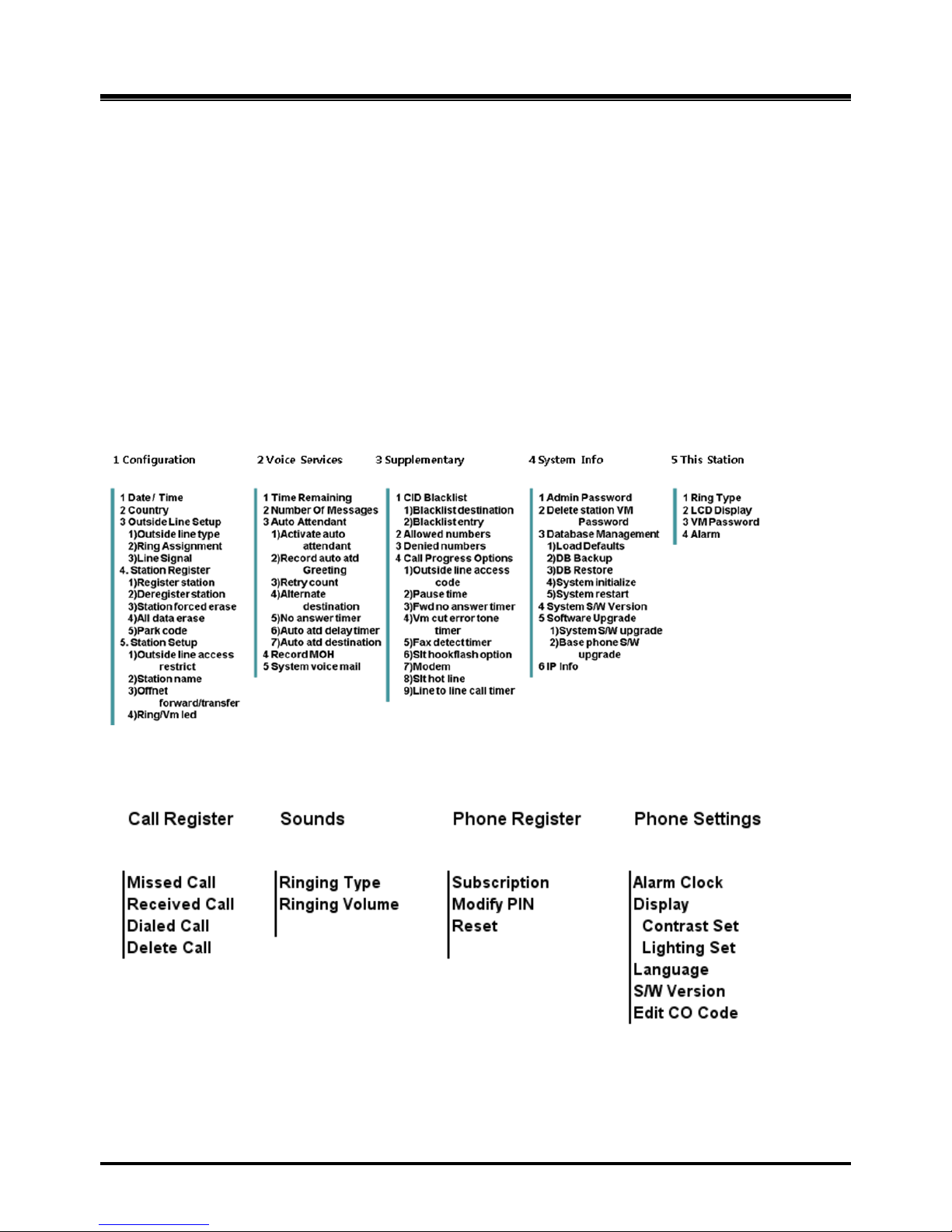
2.13 Menu Trees
2.13.1 LWS-BS Menus
2.13.2 LWS-WK Menus
Page 37

OptiCon Micro
Installation and Operation Manual
31
2.14 System Capacities
The OptiCon Micro is presently available in one configuration only as shown in the Table 2.14.1.
Table 2.14.1 OptiCon Micro System Capacity Chart
DESCRIPTION
CAPACITY
REMARK
Stations
LWS-BS station
1 Wireless Terminal
7
6 (Simultaneously)
FAX/SLT
1
Line
3 USB Host Port
1
System Speed Dial
800 (200-999)
LWS-BS
Voice Mail Box
240 minutes
Max. 3 Channel
Allow/deny list
50/50
CID Blacklist
20
System Received /Dialed call log
15/15
LWS-BS
System Missed call log
Pool of 900
LWS-BS
Table 2.14.2 Wireless Terminal Capacity
DESCRIPTION
CAPACITY
Remark
Phone book
60 Phone Dialed call log
10 Phone Received + missed call log
50
Page 38

OptiCon Micro
Installation and Operation Manual
32
3. OPERATION INSTRUCTIONS
3.1 Call Forward
Description
Users may have selected incoming calls re-routed to other stations or voice mail. Forward feature is
applied to internal calls, auto attendant line calls, & normal line calls with ring assigned only to one
station. If “OFFNET FORWARD/TRANSFER” (Menu 1 5 3) of a station is set to “ENABLE”, the station
can forward a call to external destinations.
Operation
To acti vate Call Forward:
LWS-BS station
1. Press the [Forward] soft button.
2. Select forward type.(“Unconditional”, “Busy”, “No Answer”, “Busy/No Answer”)
3. Select station number or VM.
4. Press [Save] soft button.
If OFF-NET Forward/Transfer is enabled
1. Press the [Forward] soft button.
2. Select forward type Speed, press the [Save] soft button, and dial the Speed number, or
Select forward type OFF NET, press the [Save] soft button and dial the telephone number.
Note an empty Station Directory bin is required to store the number temporarily.
3. Press the [Save] soft button.
Wireless Terminal
1. Press [Talk] key in GDC-400H/450H or [Speaker] button in LWS-WK.
2. Dial the Call Forward code (ex. 554).
3. Dial forward type (1:Unconditional, 2:Busy, 3:No Answer, 4:Busy/No Answer)
4. Dial station number or VSF/VM access code (ex.620) or,
if OFF-NET Forward/Transfer (Menu 153) is enabled,
Dial the Speed Dial access code (ex. 558) and dial the Speed dial number (200~999) or
Dial the Line access code (ex. „9‟) and dial the telephone number
5. For the LWS-WK, press the Hold button or for the GDC-400/450, press the right navigation
button, , for longer than 1 second.
To deactivate Call forward:
LWS-BS station
1. Press the [Forward] soft button in forward state.
2. Select “OFF” in forward type.
3. Press the [Save] soft button.
Wireless Terminal
1. Press [Talk] key in GDC-4XX or [Speaker] button in LWS-WK.
2. Dial Call Forward code (ex. 554).
3. Dial „#‟ to cancel Call Forward.
Page 39

OptiCon Micro
Installation and Operation Manual
33
Conditions
1. A station receiving a forwarded call can transfer the call to the forwarding station.
2. Calls cannot be forwarded to a station in DND; if attempted, an error tone is returned.
3. Call Forward status is maintained in the system‟s non-volatile memory for protection from power
outage.
4. The Forward feature is not available to SLT/FAX port.
5. A station cannot forward to another station in DND.
6. If a line is not an auto answering type and has 2 or more ring assigned stations, the call from the
line is not forwarded to the forwarded destination of ring assigned stations.
7. If the line has one ring assigned station, the call from the line will forward to forwarded destination
of the ring assigned station.
8. A station in DND cannot activate forward.
9. If an external call is forwarded to external destination (Line to line call), the call duration will be
limited to the “Line to Line call timer” (Menu 3 4 9).
10. Calls forwarded Off-Net are subject to restriction (Menu 1 5 1). The exception is calls forwarded
to speed dial numbers (200~399).
Programming
CONFIGURATION Offnet forward/transfer – [Menu] + 1 5 3
SUPPLEMENTARY Line to Line call timer – [Menu] + 3 4 9
Page 40

OptiCon Micro
Installation and Operation Manual
34
3.2 Call Pick-up
3.2.1 Directed Call Pick-Up
Description
A station may answer calls ringing at another station (Call Pick-Up). All ringing calls are subject to
Directed Call Pick-up except Queue Call-backs.
Operation
To Pick-up a call ringing at another station:
LWS-BS station and LWS-WK
1. Lift the handset or press [Speaker].
2. Dial {Directed Call Pick-up} code (7).
3. Dial the ringing station‟s intercom number.
GDC-400H/450H
1. Press ([Talk] key).
2. Dial {Directed Call Pick-up} code (7).
3. Dial the ringing station‟s intercom number.
Conditions
1. Queue call-back calls are not subject to Call Pick-up; any attempt will receive an error tone.
3.2.2 Group Call Pick-Up
Description
A station can answer (Call Pick-Up) calls ringing at another station. All ringing calls, except Queue Callbacks, are subject to Pick-up by other stations.
Operation
To Pick-up a call ringing at another station:
LWS-BS station and LWS-WK
1. Lift the handset or press the [Speaker] button.
2. Dial the Group Call Pick-up code (566).
GDC-400H/450H
1. Press ([Talk] key).
2. Dial the Group Call Pick-up code (566).
Conditions
1. Queue call-back calls are not subject to Call Pick-up; any attempt will receive an error tone.
2. When several calls are ringing simultaneously, Call Pick-up will connect the first-in, highest
priority call. Call priority order is: Line transferred call > Line hold-recalled call > Line incoming
call.
Page 41

OptiCon Micro
Installation and Operation Manual
35
3.3 Call Transfer
Description
Line calls can be transferred to other stations in the OptiCon Micro system. Calls can be transferred
announcing the call (screened) or without an announcement (unscreened).
When a Line call is transferred, the Transfer Recall Timer (30sec) is initiated. If the timer expires before the
call is answered, the Hold Recall process is initiated.
Users can transfer an active Intercom call to other stations in the wireless system, using either screened or
unscreened transfer. When used, the Intercom station is placed on Exclusive Hold, and the Transfer Recall
timer is initiated. If the timer expires before the Intercom call is answered, the call will bounce back (recall)
to the transferring station until answered or abandoned.
If “OFFNET FORWARD/TRANSFER” (Menu 1 5 3) for a station is set to “ENABLE”, the station can transfer
a call to an external destination.
Operation
While on a call, to perform a Screened Call Transfer:
LWS-BS station and LWS-WK
1. Press the [Trans] button.
2. Dial the station to receive the transfer.
3. When answered, announce the call.
4. Hang-up to complete the transfer.
To transfer a call to an external destination when “OFFNET FORWARD/TRANSFER” (Menu 1 5 3) is set to
“ENABLE”,
1. Press the [Trans] button.
2. Press desired the [LINE] button.
3. Dial the telephone number to receive the transfer.
4. When answered, announce the call.
5. Hang-up to complete the transfer.
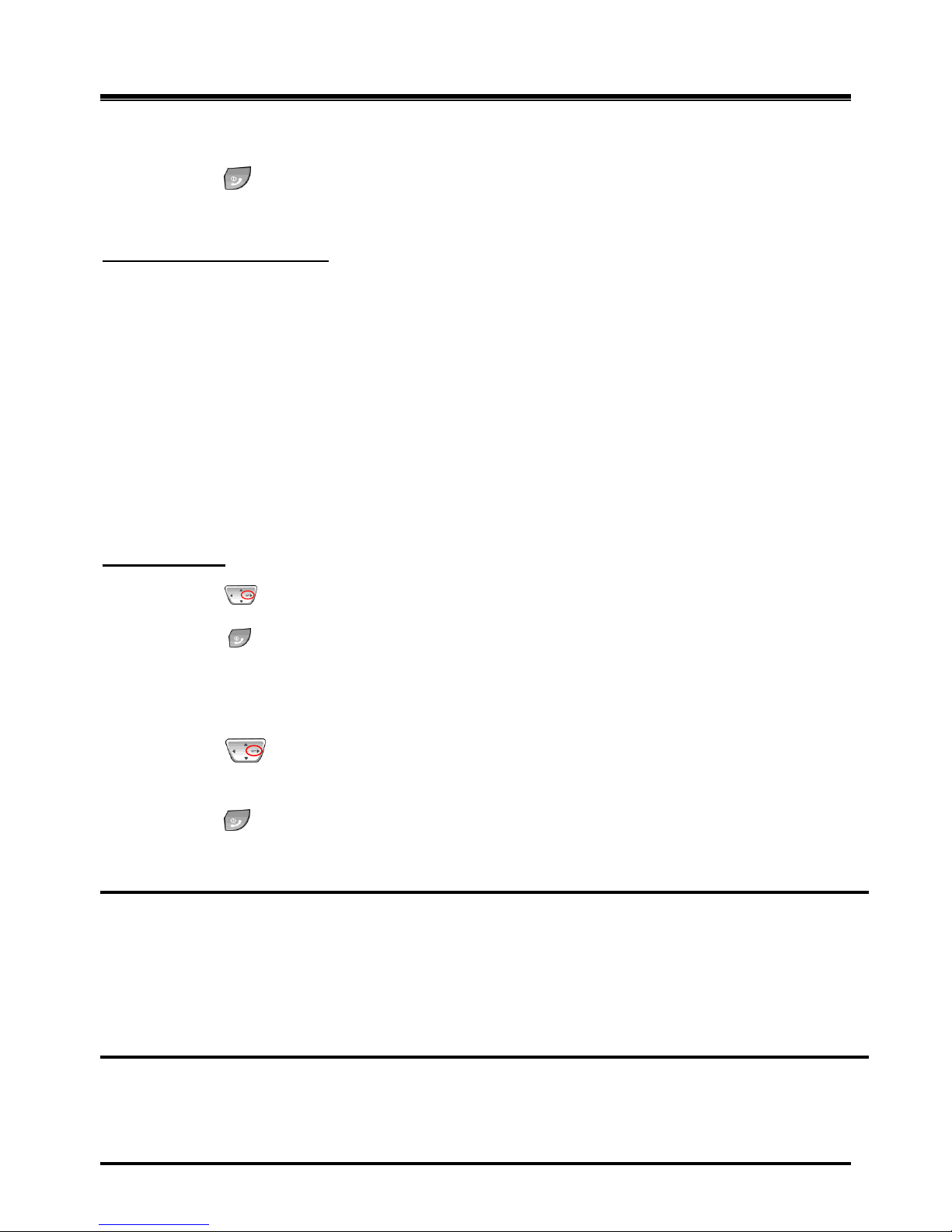
GDC-400H/450H
1. Press the ([Navigation right] key) shorter than 1 second.
2. Dial the station to receive the transfer.
3. When answered, announce the call.
4. Press the ([End] key]) to complete the transfer.
To transfer a call to an external destination when “OFFNET FORWARD/TRANSFER” (Menu 1 5 3) is set to
“ENABLE”,
1. Press the ([Navigation right] key) shorter than 1 second.
2. Dial the Line access code.
Page 42
OptiCon Micro
Installation and Operation Manual
36
3. Dial the telephone number to receive the transfer.
4. When answered, announce the call.
5. Press the ([End] key]) to complete the transfer.
While on a call, to perform an Unscreened Call Transfer:
LWS-BS station and LWS-WK
1. Press the [Trans] button.
2. Dial the station to receive the transfer.
3. Hang-up to complete the transfer.
To transfer a call to an external destination when “OFFNET FORWARD/TRANSFER” (Menu 1 5 3) is set to
“ENABLE”,
1. Press the [Trans] button.
2. Press desired {LINE} button.
3. Dial the telephone number to receive the transfer.
4. Hang-up to complete the transfer.
GDC-400H/450H
1. Press the ([Navigation right] key) shorter than 1 second.
2. Dial the station to receive the transfer.
3. Press the ([End] key]) to complete the transfer.
To transfer a call to an external destination when “OFFNET FORWARD/TRANSFER” (Menu 1 5 3) is set to
“ENABLE”,
1. Press the ([Navigation right] key) shorter than 1 second.
2. Dial the Line access code.
3. Dial the telephone number to receive the transfer.
4. Press the ([End] key]) to complete the transfer.
Conditions
1. The transferring station may camp a call to a busy station (refer to Camp-On).
2. A station in DND, out of range or out-of-service cannot receive a transfer; any attempt will result in
an error tone.
3. If an external call is transferred to external destination (Line to line call), the call duration will be
limited to the “Line to Line call timer”(Menu 3 4 9)
4. Calls transferred Off-Net are subject to restriction (Menu 1 5 1). The exception is calls transferred
to speed dial numbers (200~399).
Programming
CONFIGURATION Offnet forward/transfer – [Menu] + 1 5 3
SUPPLEMENTARY Line to Line call timer – [Menu] + 3 4 9
Page 43

OptiCon Micro
Installation and Operation Manual
37
3.4 Call Waiting/Camp-On
Description
Call Waiting is used to notify a busy station that a call is waiting. The busy station is notified of the
waiting call with a Camp-On tone. After receiving a busy signal, the calling station camps on to the called
station. The called station can respond by:
answering the waiting call, which places the active call on hold,
activating One-Time DND, or ignoring the Camp-On tone.
Operation
To acti vate a Camp-On while receiving the Intercom busy tone:
1. Press the „*‟ button, called and calling stations receive Camp-On tone.
Conditions
1. The user may only Camp-On to a station in busy mode; a user may not Camp-On to a station in
DND, conference, etc.
2. If the calling station disconnects from the call after activating Camp-On, Camp-On is cancelled.
3. A Camp-On tone is sent each time the calling user presses the „*‟ button.
3.5 LINE Access
Description
Stations can access outgoing lines. The LWS-BS station and LWS-WK may use flexible buttons assigned
to access a specific line button for outgoing calls.
Operation
To place an outgoing Line call:
LWS-BS station and LWS-WK
1. Lift the handset or press the [Speaker] button.
2. Press desired {LINE} button, dial the {line access} code (0 or 8801 ~ 8803).
GDC-400H/450H
1. Press ([Talk] key).
2. Dial the {Line access} code (0 or 8801 ~ 8803).
To answer an incoming Line call:
LWS-BS station
1. Lift the handset or press the [Speaker] button. Or,
2. Press flashing {LINE} and lift the handset to speak privately.
LWS-WK
1. Lift the handset or press the [Speaker] button.
2. In LWS-WK, it isn‟t supported to answer the incoming call by pressi ng {Line}/{Station} button in
ringing state.
GDC-400H/450H
1. Press ([Talk] key).
Page 44

OptiCon Micro
Installation and Operation Manual
38
3.6 Three-Party Voice Conference
Description
The system will allow a three party conference (internal and/or external parties can be connected on a
conference call. Only the LWS-BS station may initiate a conference call. If the base station goes onhook the conference will be terminated.
Operation
To establish an ad-hoc conference:
LWS-BS station
1. Establish the first call.
2. Press the [Conf] soft button; and the connected party is placed on exclusive hold.
3. Place the second call.
4. When connected, press the [Conf] soft button to establish 3-party conference.
Conditions
1. If the syst em receives a disconnect signal and no internal parties remain in the con ference, the
conference is terminat ed and all parties are disconnected. If an internal party is still connected
when a disconnect signal is received, the connection to remaining parties is maintained.
2. A station that is busy, in DND or other non-idle state cannot be added to a conference.
3.7 Directory
Description
A name, up to 12 characters, may be assigned to each Station and System Speed Dial. When assigned, a
user of LWS-BS may place an external call to a Station or System Speed Dial using the name.
Operation
To use Dial by Name:
LWS-BS phone
1. Press the [Direct ory] soft button
2. Select “Station directory” or “System directory”.
3. Select desired name and press the [S end] soft button
To toggle between the name and number display:
1. Press the [Select >] soft button
2. Press the [Name/Tel] soft button.
Conditions
1. The LCD will display multiple names (one per LCD line, up to 12 characters).
2. If a user selects a directory with no entries or th ere is no match to the user entry, error tone is
provided.
Page 45

OptiCon Micro
Installation and Operation Manual
39
3.8 DND (Do Not Disturb)
Description
A station can be placed in DND to block incoming Line calls, Intercom calls and transfers.
Operation
To acti vate DND:
LWS-WK
1. Press the [DND] button; the [DND] button LED illuminates.
GDC-400H/450H
1. Press the ([Talk] key).
2. Dial {DND} code (ex.553).
To remove DND:
LWS-WK
1. Press the [DND] button; the [DND] button LED extinguishes.
GDC-400H/450H
1. Press ([Talk] key).
2. Dial {DND} code (ex.553).
Conditions
1. DND service is not available to the LWS-BS station.
2. Recalls for Line calls will override the DND feature.
3. A station in DND is bypassed by calls forwarded to the station; if the last station in a Call Forward
chain is in DND, the call will ring to the previous station in the chain.
4. When calling a station in DND, the station display will indicate the DND status.
5. The forwarding station cannot activate the DND feature.
6. The station forwarded from the LWS-BS station cannot activate the DND feature.
3.9 Headset Compatibility
Description
LWS-BS station
The [Headset] button may be used only to select the mode between headset and speakerphone in idle
state. In busy/talking state, the switchover between headset and speakerphone is not supported.
In the headset mode, pressing the [Speaker] button will send audio to th e Headset instead of the
speakerphone.
LWS-WK
By pressing the [Headset] button, the user can use headset, immediately.
In talk mode with the headset, if the user presses the [Speaker] button, the user can talk with the
speakerphone.
Page 46

OptiCon Micro
Installation and Operation Manual
40
Operation
LWS-BS station
To select Headset mode:
1. Press the [Headset] button.
2. The LED of [Headset] button is turned on.
To place/a nswer calls using the headset:
1. Press the [Speaker] with the phone in Headset mode.
LWS-WK
To place/a nswer calls using the headset:
1. Press the [Headset] button.
3.10 Hold
3.10.1 Hold
Description
Lines may be placed in a waiting state such that other stations in the system are able to access the Line. If
the call remains on hold at expiration of the System Hold Recall Timer, normal Hold Recall will be activated.
Operation
To place a call on System Hold:
LWS-BS stat
ion
and LWS-WK
1. Press the [Hold] button.
GDC-400H/450H
1. Press ([Navigation] right key) longer than 1 second.
To access a call from System Hold:
LWS-BS stat
ion
and LWS-WK
1.
Press the {LINE} button.
OR
1. Lift the handset or press the [Speaker] button.
2. Dial the {Held Individual LINE Access} code (ex. 8#).
3. Dial the Line number (01-03
OR
1. Lift the handset or press the [Speaker] button.
2. Dial {Held Line Access} code (ex. 8*).
GDC-400H/450H
1. Press ([Talk] key).
2. Dial {Held Individual LINE Access} code (ex. 8#).
3. Dial the Line number (01-03)
OR
1. Press ([Talk] key).
2. Dial {Held Line Access} code (ex. 8*).
Page 47

OptiCon Micro
Installation and Operation Manual
41
Conditions
When a Line is placed on System Hold, the button LED will flash (it will flash at the hol ding station and will
flash at all other stations).
A call on System Hold can be retrieved from any station allowed access to the Line in the system database
using the Line button or the Held Line call access code.
3.10.2 Hold Recall
Description
When a user places a Line call on hold, a hold timer is activated. If the timer expires, the held call will recall
at the station for the I-Hold Recall time (30sec). If the call remains unanswered, the call is placed on
System Hold and the LWS-BS station also receives a recall for the Attendant Recall time (1minute). If still
unanswered after the Attendant Recall time , the Line call is disconnected and the appropriate circuits are
returned to
idle.
Operation
Hold Recall operation is automatic.
3.10.3 Automatic Hold
Description
While on an active Line call, the system will place the ca ll on hold automatically if the user presses a
{Station/Line} button.
In this case, pressing a {Line} button while on a Line call will place the active call on hold and access the
selected Line.
Operation
To use Automatic Hold while on an active Line call:
LWS-BS station
1. Press the desired feature button or {Line} button; the active call is placed on Hold.
Conditions
1.
There is no limit on the number of calls that can be placed on Hold using Automatic Hold
up to the
number of Lines connected to the system.
3.11 PARK Code
Description
Is used for the re-programming of PARK code.
Operation
LWS-BS station
To program PARK code:
1. Press the [Menu] button.
2. Dial 145.
3. Press [Change] soft key and type new PARK code.
Page 48

OptiCon Micro
Installation and Operation Manual
42
3.12 CID Blacklist
Description
The system can employ the Caller identification number to determine the routing of incoming external calls.
The system will compare the received Caller ID to entries in the CID Blacklist, and if a match is found, will
route the call to the Voice mail of base station or disconnect the call.
Programming
CONFIGURATION Blacklist destination – [Menu] + 3 1 1
Blacklist entry– [Menu] + 312
3.13 Allow/Deny Number (Call Barring)
Description
Allow/Deny list has 50 codes and each code can contain up to 20 Digits. This list are applied to the user with
Outside Line access restriction (Menu + 1 5 1) enabled.
As digits are 42dialed, they are compared to entries using the following rules to allow or deny the call.
Rule 1 – If a table has no entries, no restrictions are applied.
Rule 2 – If there are only Deny entries, restrictions are provided as Deny only.
Rule 3 – If there are only Allow entries, restrictions are provided as Allow only.
Rule 4 – If there are both Allow and Deny entries, the Deny entries are searched . If the dialed number
matches a Deny entry, the call is restricted; if no match is found the call is allowed.
This feature is not applied to System Speed numbers 200~399”. Therefore, the user can make a call with
System Speed number 200~399” with no restriction.
Programming
CONFIGURATION Line Access Restriction – [Menu] + 1 5 1
Allow list – [Menu] + 3 2
Deny list - [Menu] + 3 3
3.14 MOH(Music-On-Hold)
Description
When a call is placed on hold, the system will deliver a recorded message form VSF or the default MOH
tone. In this way, the connected user can determine that the connection is still active.
The base station records the VSF message for MOH. If message is not recorded, the default MOH will
be delivered.
Page 49

OptiCon Micro
Installation and Operation Manual
43
Operation
LWS-BS station
To record a VSF message for MOH:
1. Press the [Menu] button.
2. Dial 2 4.
3. Dial „#‟.
4. After the record prompt and beep-to ne, record message.
5. Press the [Save] button to stop recording and save the MOH message.
3.15 Speed Dial
3.15.1 Display Security
Description
Individual and common Speed Dial numbers may be programmed so that the digits are not displayed on
the LCD of the LWS-BS station.
Operation
1. To assign Display Security to a Speed Dial number:
Dial “*” as the first digit of th e Speed Dial number.
Conditions
1. The number is displayed when programming a Speed Dial number.
2. Display Security is provided on all Line calls including calls that are transferred or recall.
3.15.2 Station Speed Dial
Description
The LWS-BS station can store commonly dialed numbers for easy access using Station Speed Dial bins.
The base station has access to 20 Speed Dial numbers.
Operation
To dial using a Station Speed Dial:
1. Lift handset or press the [Speaker] button.
2. Press the [Direct ory] button.
3. Press the [Speed] button.
4. Dial the desired bin number (00–19).
Page 50

OptiCon Micro
Installation and Operation Manual
44
To program an Individual Speed Dial number:
1. Press the [Direct ory] button.
2. Press the [Speed] button.
3. Press the [Add] button.
4. Dial the Speed Dial bin number (00-19).
5. Press the {Line} button or dial the Line access code (ex. 0 or 8801 ~ 8803).
6. Dial the number to be stored.
7. Press the [Save] soft button.
8. If desired, enter a name.
9. Press the [Save] soft button.
Conditions
1. Accessing an empty Speed Dial bin will return an error tone.
2. All Speed Dial numbers are stored in memory protected from power loss.
3. A name can be entered for a Speed Dial number to permit access from the Directory.
3.15.3 System Speed Dial
Description
Commonly dialed numbers can be stored by the LWS-BS station. Up to 800 System Speed Dial numbers
are available. Each Speed Dial number can be up to 23 digits in length and may include special
instruction codes.
Operation
To dial using a System Speed Dial:
1. Lift the handset or press the [Speaker] button.
2. Press the [Direct ory] soft button.
3. Press the [Speed] soft button.
4. Dial the desired bin number („200‟-„999‟).
LWS-WK
1. Lift the handset or press the [Speaker] button.
2. Dial the {Speed Dial Access} code (ex. 558) or press the [Speed] soft button.
3. Dial the desired bin number („200‟-„999‟).
GDC-400H/450H
1. Press the ([Talk] key).
2. Dial the {Speed Dial Access} code (ex. 558) or press the [Speed] button ( ).
3. Dial the desired bin number („200‟-„999‟).
Page 51

OptiCon Micro
Installation and Operation Manual
45
To program a System Speed Dial number:
LWS-BS station
1. Press the [Directory] soft button.
2. Press the [Speed] soft button.
3. Press the [Add] soft button.
4. Dial the Speed Dial bin number (200-999).
5. Press the {Line} button or dial the Line access code (ex.9, 8801 ~ 8803).
6. Dial the number to be stored.
7. Press the [Save] soft button.
8. If desired, enter a name.
9. Press the [Save] soft button.
Conditions
1. Accessing an empty Speed Dial bin will return error tone.
2. All Speed Dial numbers are stored in memory protected from power loss.
3. A name can be entered for a Speed Dial number to permit access from the Directory.
4. If a Speed Dial number contains a “Dial-Tone Detect” command, Flash as the first entry in the bin
and dial tone detect is enabled for the Line, the system must detect dial tone before dialing the
Speed Dial number.
5. The “Allowed/Denied Number” feature is not applied to System Speed numbers 200~399.
Therefore, the user can make a call with System Speed number 200~399 with no restriction.
3.16 VSF Integrated Auto Attendant/Voice Mail
3.16.1 VSF
Description
The Voice Store & Forward (VSF) unit, which is equipped in the OptiCon Micro, provides the system
memory to support the integrated Auto Attendant, Voice Mail, and system announcement applications
available in the System. The memory is employed to store Auto Attendant announcements, voice mail,
greetings, and messages, and various system prompts. The VSF has storage capacity of up to 240
minutes.
3.16.2 Auto Attendant Announcement (DISA Service)
Description
When a line is set “Auto Attendant” to “ON”(Menu 2 3 1) and “Auto Atd destination” to “Greeting”(Menu 2 3
7), if a call comes into the system through the Line, the call may be routed to a recorded VSF
Announcement.
There are 4 Auto Attendant Announcements. These announcements can be recorded in [Menu] 232.
If “COMMON” announcement is recorded, then it is applied to all lines.
If “LINE 1” is recorded, then it is applied to only line 1.
Page 52

OptiCon Micro
Installation and Operation Manual
46
If „COMMON” is recorded, and “LINE 1” is also recorded, then “COMMON” is applied to line 2 and line 3,
and “LINE 1” is applied to line 1.
If the caller dials a station number, the Auto Attendant will complete an unsupervised call transfer to the
station.
Operation
To record an Auto Attendant Announcement:
LWS-BS station
1. Press the [Menu] button.
2. Dial 2 3 2.
3. Select the type (“COMMON”, “LINE 1”, “LINE2”, “LINE3”) with Navigation up/down button and
press [OK] soft button.
4. Dial „#‟.
5. After the Record prompt and beep-tone, record the message.
6. Press the [Save] soft button to stop recording and save the message.
To delete a recording:
LWS-BS station
1. Press the [Menu] button.
2. Dial 2 3 2.
3. Select the type (“COMMON”, “LINE 1”, “LINE2”, “LINE3”) with Navigation up/down button and
press [OK] soft button.
4. Press the [Delete] soft button.
Conditions
1. If the external caller dials a station number and the station is busy or there is no answer, the call is
routed by busy/error/no answer (Exception) destination (Menu 2 3 4).
2. No answer routing time is set by the No answer Timer (Menu + 2 3 5).
3. The greeting is played by retry count (menu + 2 3 3).
4. If "Auto Atd delay timer" (Menu 2 3 6) is not „0‟, the external call will ring to the assigned stations
for this timer. If not answered, the call will be routed to the recorded Announcements.
5. If both “COMMON” Announcement and “LINE 1/2/3” Announcement are recorded, “LINE 1/2/3”
Announcement will play. That means, LINE 1/2/3 priority is higher.
6. If “COMMON” Announcement is recorded and “LINE 1/2/3” Announcement is not recorded,
“COMMON” Announcement will play.
7. If neither “COMMON” Announcement nor “LINE 1/2/3” Announcement are recorded, call is routed
to ring-assigned stations.
Programming
VOICE SERVICES Activate auto attendant – [Menu] + 2 3 1
Record auto atd greeting – [Menu] + 2 3 2
Auto atd delay timer – [Menu] + 2 3 6
Auto atd destination – [Menu] + 2 3 7
Page 53

OptiCon Micro
Installation and Operation Manual
47
3.16.3 Auto Attendant Recording (Leave Voice message)
Description
When a Line is set “Auto Attendant” to “ON”(Menu 2 3 1) and “Auto Atd destination” to “System VM”(Menu
2 3 7), if a call comes into the system through the Line, the call is routed to “System voice mail”.(refer to the
3.27 System voice mail), caller can leave a message.
Maximum recording time is 1 minute.
If “VM code of System Voice mail” code is assigned to a flexible button of LWS-BS station or LWS-WK, the
flexible button will be flashing if new voice mails are existed in voice mail box of the station assigned
“System Voice mail”.
“VM code of System Voice mail” code is “VM‟ code(ex. 620) + station number of “System Voice mail”.
For example, “VM” code is 620 and the station number of “System Voice mail” is “102”, “VM code of
System Voice mail” code is 620102.
When the “VM code of System Voice mail” button is flashing,
If a user press the “VM code of System Voice mail” button and dial the station number of “System voice
mail” and dial the voice mail password of the station assigned “System voice mail”, the user can access the
voice mail box of the station assigned “System Voice mail”.
Operation
To assign “VM code of System Voice mail” code to a flexible button in LWS-BS station or LWS-WK,
1. Press [Speaker] button.
2. Press [Trans] button.
3. Press a flexible button.
4. Enter “VM code of System Voice mail”.(ex. 620102).
5. Press [Hold] button.
Conditions
1. If "Auto Atd delay timer" (Menu 2 3 6) is not „0‟, the external call will ring to the assigned
stations for this timer. If not answered, the call will be routed to “System voice mail”, and caller
can leave a voice message.
Programming
VOICE SERVICES Activate auto attendant – [Menu] + 2 3 1
Auto atd delay timer – [Menu] + 2 3 6
Auto atd destination – [Menu] + 2 3 7
System voice mail - [Menu] + 2 5
Page 54

OptiCon Micro
Installation and Operation Manual
48
Description
When a station activates Call Forward to the VSF, calls to the station will forward to the station VSF
mailbox. The caller receives the called station‟s User Greeting followed by a beep tone.
The remote caller can record a message and hang-up or dial „*‟ for further options. The VM application
stores the message in the called user‟s voice mailbox and activates the Message Waiting indication at the
user‟s station. If the “Ring/Vm LED” (Menu 1 5 4) of the station is set to “VM”, the Ring indication LED of
the station will flash to indicate a new voice mail (LWS-BS and LWS-WK only).
Operation
Remote Caller
To leave a voice message after hearing announcement:
1. Wait for the beep and then leave a message.
2. Hang up to quit recording,
OR
2. Dial „*‟ for more options.
Conditions
1. If all the VSF channels are in use, Ring Back tone is provided until a VSF channel is available.
2. Individual User Greetings and Voice Mails are protected from AC power loss.
3. When a voice mail is left, the end of the message will contain error tone. The error tone can be
eliminated employing the VM Cut error tone timer. The system will delete, from the end of the
message, the portion of the message defined by the VM Cut Error Tone timer.
Programming
CONFIGURATION Ring/Vm Led – [Menu] + 1 5 4
SUPPLIMENTARY Vm cut error tone timer – [Menu] + 3 4 4
3.16.4.2 Message Retrieval
Description
A user can access their Mail Box locally by placing a call to the VSF Voice Mail group, by pressing the
[MSG] button, or by dialing VSF voice mail code (ex. 620)
Page 55

OptiCon Micro
Installation and Operation Manual
49
Prompts are then received to guide the user in the Voice Mailbox operation. The user must enter a Mail
Box number, generally the station number, and a corresponding password in response to the "Request for
Password" ("Please enter your password code.") prompts.
If the user enters a valid and matching Mailbox and password, the "Number of Messages" prompt (“You
have xx new messages, You have yy saved messages.”) is received. At this point, the user also receives
the “VM long option prompt” (“To play new messages, press one, to play saved messages, press two, to
set greeting or password, press eight, to disconnect, press pound, Press 0 for the operator, Press nine to
hear this message again.”).
When the user responds by dialing 1, the first new message is played. At the end of message playback,
the "New Message option" prompt is played (“To replay message, press one, to listen to the next message,
press two, to delete message, press three, to forward message, press four, to call the sender, press five, to
skip message, press six, to return to main menu, press nine.”). This process is repeated until the last new
message is played and the "No Message" prompt (“No Messages") is played.
When the user dials 2 in response to the "Number of Messages" prompt, the first-saved message is played.
At the end of the message, the "Saved Message option" prompt is played (“To replay message, press one,
to listen to the next message, press two, to delete message, press three, to forward message, press four,
to call the sender, press five, to return to main menu, press nine.”). This process is repeated until the last
saved message is played and the "No Message" prompt (“No Messages") is played.
In addition to the options indicated in the prompt, a user can record a memo, which is attached to the
current voice mail by dialing the digit 7. The current voice mail and memo can then be forwarded to other
Mailbox users.
When the user dials 9 in response to the "Number of Messages" prompt or during or at the end of a
message the "VM long Options" prompt is played.
Operation
To register password for voice mail:
LWS-BS station
1. Press the [Menu] button.
2. Press 5 3.
3. If a current password exists, enter the station number and current password.
4. Press the [Save] soft button.
5. Enter the station number and new password
6. Press [Navigation] down button.
7. Enter the station number and new password.
8. Press the [Save] soft button.
Page 56

OptiCon Micro
Installation and Operation Manual
50
LWS-WK
1. Press [Speaker] button.
2. Press {Change VM password} code (ex.559).
3. If a current password exists, enter the station number and current password.
4. Press [Hold] button.
5. Enter the station number and new password
6. Press [Hold] button in LWS-WK.
GDC-400H/450H
1. Press the ([Talk] key).
2. Press {Change VM password} code (ex.559).
3. If a current password exists, enter the station number and current password.
4. Press the ([Navigation] right key) longer than 1 second.
5. Enter the station number and new password.
6. Press the ([Navigation] right key) longer than 1 second.
To remove password for voice mail:
1. Press the [Menu] button in LWS-BS station.
2. Press 4 2.
3. Select the station number with [Navigation] right/left button.
4. Press the [OK] soft button.
For Australia, this process will return the password to default, the station number and „*‟.
To retrieve Voice Mail locally:
LWS-BS station
1. Lift the handset or press the [Speaker] button.
2. Dial the {Voice mail} code (ex. 620).
3. Dial the Mailbox number (station number) and corresponding password to receive the “Number of
Messages” prompt.
4. Dial desired option code.
5. At completion of session, hang-up to return to idle.
LWS-WK
1. Lift the handset or press the [Speak] button.
2. Dial the {Voice mail} code (ex. 620).
3. Dial the Mailbox number (station number) and corresponding password to receive the “Number of
Messages” prompt.
4. Dial desired option code.
5. At completion of session, hang-up to return to idle.
Page 57

OptiCon Micro
Installation and Operation Manual
51
GDC-400H/450H
1. Press the ([Talk] key).
2. Press Dial the {Voice mail} code (ex. 620).
3. Dial the Mailbox number (station number) and corresponding password to receive the “Number of
Messages” prompt.
4. Dial desired option code.
5. At completion of session, press the ([End] key) to return to idle.
Conditions
1. Messages are retrieved in LIFO (Last in First out) order.
2. The default password for voice mail is „*‟.
3. If the user removes the password for voice mail, access to the voice mailbox is not possible.
4. If password is lost or forgotten, first remove the password using the LWS-BS station and change
the password at his phone (refer to operation).
3.16.4.3 Remote Message Retrieval
Description
The system permits remote users access to their mailbox. After accessing the VSF Voice Mail, operation
follows the local procedures.
Operation
To access Voice Mailbox from a remote location
1. Lift the handset.
2. Dial the telephone number of a DISA assigned CO line assigned for answer by a Auto
attendant greeting.(refer to the 3.25.2 Auto Attendant Announcement)
3. Upon answer, dial „#‟ to receive the “Enter password” prompt.
4. Dial the Mailbox number (station number) and corresponding password to receive the “Number
of Messages” prompt.
5. Dial desired option code.
6. At completion of session, hang-up to return to idle.
Conditions
1. The conditions associated with Message Retrieval and Message Retrieval Options apply.
Programming
VOICE SERVICES Activate auto attendant – [Menu] + 2 3 1
Record auto atd greeting – [Menu] + 2 3 2
Auto atd destination – [Menu] + 2 3 7
Page 58

OptiCon Micro
Installation and Operation Manual
52
3.16.4.4 Message Retrieval Options
Description
The user may dial the digit „9‟ to receive the “VM Long Options” prompt while in the Voice Mailbox,
including during or after a voice message or system prompt, except when an option has been selected that
requires user dialing. Some options involving user dialing include the Message Retrieval Option 1/2 (Play
New/Saved Message), 7 (Cancel or Forward message, Remote Access Only) or 8 (Mailbox settings), refer
to Table. The “VM long Options” prompt is:
"To play new messages, press one, to play saved messages, press two, to set station forwarding, press
seven (This option is available only for remote access), to set greeting or password, press eight, to
disconnect, press pound, Press „0‟ for the operator, Press nine to hear this message again."
The VSF Voice Mail will respond to incoming digits as shown in the following table.
Digit
Function
1
Play New MSG
2
Play Saved MSG
7
Set Cancel/Fwd, available only for remote access
8
Mail Box Setting, "Mailbox Settings" prompt
9
VM Long options
#
Drop, "Goodbye”
0
Attd Call, Call to Attendant.
Operation
To access a Message Retrieval option.
At any time after the “Number of Messages” prompt, dial a Message Retrieval Option digit. The system
initiates the selection providing any needed prompts.
3.16.4.5 Voice Mailbox Settings
Description
The user can program the Mailbox settings for their mailbox including a security password and a greeting.
When a user presses "8" while retrieving messages, the "Mailbox Setting" prompt (“To edit your greeting,
press one, to edit you password, press two. To return to main menu, press nine”) is played.
Operation
To program Mailbox settings while “in” the Voice Mail Box:
Press „8‟, for Mailbox settings; the “Mailbox Setting” prompt is received.
Page 59

OptiCon Micro
Installation and Operation Manual
53
To enter a new password:
1. Dial „7‟ to receive the “Password Entry” prompt (“Please enter your new password and press
pound when finished.").
2. Dial new password.
3. Press „#‟; the “Re-enter Password” prompt will be heard ("Please re-enter your password to
confirm and press pound when finished.").
4. Dial new password again.
5. Press „#‟ and the “Password Confirmation” prompt will be heard ("Your password is saved.").
To create a new greeting:
1. Dial „4‟ to hear the “Greeting Option” prompt ("To listen to your current greeting, press five to
record a new greeting, press seven, to return to the main menu, press nine.”).
2. Dial „5‟, to hear your greeting.
OR
3. Dial „7‟ to hear the “Record Greeting” prompt ("At the tone, record your new greeting, press #
when done.").
4. After the beep, record your desired greeting speaking in a normal voice.
5. Press „#‟ and receive the “Greeting Confirmation” prompt ("Your greeting is saved.").
To adjust Mailbox Settings:
1. Dial „9‟ to hear the “Mailbox Setting prompt” (“To edit your greeting, press one, to edit your
password, press two, to return to main menu, press nine”).
Conditions
1. If the dialed number is not recognized, the "Invalid Entry" prompt is played.
2. The user must assign a password (Authentication code, up to 12 digits) before access to the
mailbox will be allowed.
3.16.4.6 Call Forward from VM
Description
External users can activate or deactivate Call Forward for their station. Pressing „7‟ while retrieving
messages will return the "Mailbox Set Forward" prompt, (“To forward calls to another extension, press one.
to cancel forwarding, press „2‟ to return to the main menu, press nine.”).
Operation
To activate Call Forward while in the VM:
1. Press „7‟, for Mailbox set forward, the “Mailbox Set Forward” prompt is received.
Page 60

OptiCon Micro
Installation and Operation Manual
54
To activate Call Forward:
1. Dial „1‟ and receive the “Destination Entry” prompt (“Please enter the number to forward to").
2. Dial the Station Number as follows:
To forward to another station, dial the station number.
To deactivate Call Forward:
1. Dial „2‟ and receive the “Station forwarding is canceled” prompt.
To return to the Main menu:
1. Dial „9‟ and receive the “Mailbox Settings” prompt.
Conditions
1. If the user is external, the user must begin dialing within and dial subsequent digits within the VSF
Inter-Digit Timer; if not, the call is released.
2. The Mailbox Set Forward is only available for external users.
3.16.4.7 Voice Mail error tone cut timer
Description
When external callers have left a voicemail message the LWS listens for busy tone to end the call, the VSF
records these few seconds of busy tone and will play them back when you retrieve your messages. The
VM error tone cut timer will truncate the end of the message.
Setting this timer too high could result in part of voicemail messages being permanently deleted.
Operation
To set cut time
1. Press the [Menu] soft button.
2. Dial 3 4 4
3. Enter the time in seconds (00~99).
4. Press the [Save] button.
3.17 Wake-Up Alarm
Description
This feature allows a user to set a wake-up time or desired time to be alerted. When the time is
reached, the system will signal with an audible and visual signal.
Operation
To register Wake-Up:
LWS-BS station
1. Press the [Menu] button.
Page 61

OptiCon Micro
Installation and Operation Manual
55
2. Dial 5 4.
3. Select “Single” or “Continuous”
4. Dial 2-digit hour and 2-digit minute for alerting.
5. Press the [Save] button.
To erase Wake-Up:
LWS-BS station
1. Press the [Menu] button.
2. Dial 5 4.
3. Select “OFF”.
4. Press the [Save] button.
Conditions
1. The Wake-up alarm Ring signal is 30 seconds, On/90 seconds, Off (3 times). If no action is
taken by the user, the ring signal is given to the Attendant with a display designating the station
number that did not respond.
2. Time (hh:mm) must be entered in the Military 24-hour format.
3. The daily alarm will reset and repeat each day until cancelled. The One-time alarm will reset
and cancel automatically.
3.18 Intercom Call (ICM Call)
Description
A non-blocking ICM is available to all stations in the system. Users may place an intercom call to other
stations in the system by dialing applicable digits as defined in the system Numbering Plan.
Operation
To place an intercom call:
LWS-BS station and LWS-WK
1. Lift the handset or press the [Speaker] button to receive ICM dial tone.
2. Dial station number or press the {Station} bu tton.
3. For ring-back tone, await answer.
GDC-400H/450H
1. Press ([Talk] key) to receive ICM dial tone.
2. Dial station number.
3. For ring-back tone, await answer.
Conditions
1. Intercom Dial tone will time-out if action is not taken within Dial-Tone Time or, if the time between
digits exceeds the Inter-digit Timer; error tone is received.
2. ICM Dial tone is halted after dialing the first digit.
3. If the called station is busy, Intercom Busy tone is provided for the Busy Tone time (7 sec.) then,
Error tone is sent by the system; the caller may disconnect or activate a feature such as Voice
Message prior to receiving error tone.
Page 62

OptiCon Micro
Installation and Operation Manual
56
3.19 Intercom Call Hold
Description
While on an active ICM Call, Users can place the ICM Call on hold; the held station will receive the
assigned MOH. The call is placed on Exclusive Hold and recalls at the holding station after the station
returns to idle.
Operation
To place an active ICM call on hold:
LWS-BS station and LWS-WK
1. Press the [Hold] button.
GDC-400H/450H
1. Press ([Navigation] right key) longer than 1 second;
To retrieve the held ICM call:
LWS-BS station and LWS-WK
1. Press the {Station} button associated with the held station.
GDC-400H/450H
1. Dial a station number of held station;
Conditions
1.
Only one ICM call may be placed on hold at a time.
3.20 Line Ring Assignment
Description
Each station in the system can be programmed to provide an audible signal when the system detects an
incoming call on specified Lines.
Operation
To set “Line ring assignment”:
LWS-BS station
1. Press the [Menu] button.
2. Dial 1 3 2.
3. Select a Line.
4. Press the button corresponding to the desired station, the button will light red to indicate that ring
is set to on.
5. A delay of 0 to 9 rings can be programmed.
Page 63

OptiCon Micro
Installation and Operation Manual
57
Conditions
1. A busy station receives muted ring or Call Waiting tones (as appropriate) for the station‟s off-hook
ring assignment. In Night/weekend mode, Line ring assignment is disabled.
2. In case of the GDC-400H/450H and LWS-WK, a maximum of 6 stations can be assigned for each
line.
3.21 Night/Weekend mode
Description
In Night/Weekend mode, a specific station or “System voice mail” is assigned as the ring destination for all
calls on a Line.
Operation
LWS-BS station
To activate Night/Weekend mode:
1. Press the [DND] button.
2. Select the ring destination or “System VM”.
3. Press the [Save] soft button. Then the DND LED is turned on.
To deactivate Night/Weekend mode:
1. Press the [DND] button.
2. Select “OFF”.
3. Press the [Save] soft button. Then the DND LED is turned off.
Conditions
1. In Night/Weekend mode, the DND LED of base station is turned on.
2. If the LWS-BS station is forwarded to another station, the user can activate/deactivate the
Night/Weekend mode at the receiving station.
3. If the ring destination of Night/Weekend mode is set to “System Vm”, the caller can leave a voice
message to the voice mailbox of the station assigned for “System voice mail” (Menu 2 5).
Programming
VOICE SERVICES System voice mail – [Menu] + 2 3
3.22 Call Log Display
Description
The LWS-BS station can view a log of incoming, outgoing and missed calls on the display and place a call
from the call log.
Page 64

OptiCon Micro
Installation and Operation Manual
58
Operation
LWS-BS station
To place a call with Call Log:
1. Press the [Call log] soft button.
2. Select “received” , “dialed” or “missed”
3. Select the desired number and press [Send] soft button.
To delete Call Log:
1. Press the [Call log] soft button.
2. Dial 4.
3. Select the option and press the [OK] soft button.
Conditions
1. Maximum count of Received and Dialed call logs is 15 each.
2. Missed call logs are saved as a pool of 900 numbers. If the Missed Call Log pool is full, the new
missed calls are not logged.
3. Missed call logs can be saved to speed dial, but received/dialed call logs cannot be saved to
speed dial.
3.23 Mute
Description
The user can turn off audio transmission from the handset, speakerphone or headset microphone (Mic
Mute).
Operation
LWS-BS station
To Mute the Microphone:
1. Press the [Mute] button; the [Mute] button LED illuminates, the microphone (Handset,
Speakerphone and Headset) is muted, and the connected party receives silence.
To acti vate the mi crophone:
1. Press the illuminated [Mute] button; the [Mute] button LED extinguishes. The microphone is
then activated and audio is transmitted to the connected party.
Page 65

OptiCon Micro
Installation and Operation Manual
59
3.24 Tel/Fax Line
Description
If Tel/Fax Line Mode (Menu 1 3 1) is selected, the system will detect a FAX tone within the fax tone
detection time. After detecting FAX tone, the system sends the call to the SLT/FAX port to respond to it.
If a FAX tone is not detected within the fax tone detection time, the system will transfer the call to the ring
assigned stations for that particular Tel/Fax line.
Operation
To set Tel/fax line:
LWS-BS station
1. Press th e [Menu] button.
2. Dial 1 3 1.
3. Select “Tel/Fax” with [Navigation right/left] button.
4. Press [Save] soft button.
Conditions
1. The fax tone detection time is 10 seconds.
2. The auto attendant feature isn‟t applied to Tel/Fax Line
3.25 SLT/Fax/Modem port
3.25.1 Modem Operation
Description
The SLT/Fax port is assigned to the last station number (ex: 108 in 100-108). This port is intended for use
by an SLT, FAX, or modem. When modem use is desired, the “MODEM” ([Menu] 3 4 7) must be set to
“ON”. In all other cases, the “MODEM” must be set to “OFF”. FAX operation from the port is available
regardless of “MODEM” setting.
Operation
To use FAX machine/single line telephone,
LWS-BS station
1. Press the [Menu] button.
2. Dial 3 4 7. “Modem” menu.
3. Select “OFF”.
4. Press the [Save] soft button.
To use FAX machine/modem,
LWS-BS station
1. Press the [Menu] button.
2. Dial 3 4 7. “Modem” menu.
3. Select “ON”.
4. Press the [Save] soft button.
Page 66

OptiCon Micro
Installation and Operation Manual
60
Conditions
1. Calls to SLT/Fax port cannot be picked up.
2. The Camp-on feature is not allowed to a busy SLT/Fax port.
3. Voice messaging is not available for the SLT/Fax port.
Programming
SUPPLEMENTARY Modem – [Menu] + 3 4 7
3.25.2 SLT Hot Line
The SLT/Fax port is assigned to the last station number (ex: 108 in 100-108). This port is intended for use
by an SLT, FAX, or modem. The port can be configured to automatically access a CO Line when the
connected device goes off-hook. The Hot Line can be configured as:
Off – No Hot Line operation
Idle Line – select an idle line when the SLT port goes off-hook
Line 1 – select Line 1 when the SLT port goes off-hook
Line 2 – select Line 2 when the SLT port goes off-hook
Line 3 – select Line 3 when the SLT port goes off-hook
In addition, the action the system will take when a hook-flash is detected from the device connected to the
port can be configured as
Flash Xfer: hook-flash, dial tone received then transfer as usual.
Flash Drop: hook-flash, then previous call is dropped.
Flash Ignore: hook-flash, nothing happens.
Hold Release: hook-flash, Held Line is released when the SLT goes On-Hook.
Operation
To select the SLT Hot Line function from the LWS-BS,
1. Press the [Menu] button.
2. Dial 3 4 8.
3. Select the desired Hot Line (Off, Idle Line, Line 1, Line 2, or Line 3).
4. Press the [Save] soft button.
To select hook flash function from the LWS-BS,
1. Press the [Menu] button.
2. Dial 3 4 6.
3. Select the desired option for hook flash.(“FLASH XFER”, “FLASH DROP”, “FLASH IGNORE”,
“HOLD RELEASE”)
4. Press the [Save] soft button.
Page 67

OptiCon Micro
Installation and Operation Manual
61
Conditions
1. The Forward feature is not available for SLT/Fax port.
2. Calls to SLT/Fax port cannot be picked up.
3. The Camp-on feature is not allowed to a busy SLT/Fax port.
4. Voice messaging is not available for the SLT/Fax port.
Programming
SUPPLEMENTARY SLT hook flash option – [Menu] + 3 4 6
SUPPLEMENTARY SLT Hot Line – [Menu] + 3 4 8
3.26 Phone book (GDC-400H/450H & LWS-WK)
Description
The GDC-400H/450H and LWS-WK incorporate a Phonebook that stores up to 60 contact records with a
name and phone number. The name can be up to 14 digits in length (characters and numbers). From the
Phonebook, records can be searched, called, added, modified, or deleted. When a call is received from a
contact in the Phonebook, the name associated with the number is displayed.
There are several methods to access the Phonebook menu based on the state of the phone, idle or busy.
Operation
To access the Phonebook menu while the phone is in an idle:
LWS-WK
1. Press the [P.BOOK] soft button.
GDC-400H/450H
1. Press the Names ( ) right soft button,
OR
1. Press the down arrow on the Navigation button.
To access the Phonebook menu while the phone is busy:
LWS-WK
1. Press the [OPTION] soft button.
2. Use the [Navigation] button to highlight the Phonebook selection and press the [OK] soft button.
Page 68

OptiCon Micro
Installation and Operation Manual
62
GDC-400H/450H
1. Press the Option ( ) left soft button; this displays the Options menu.
2. Use the [Navigation] ( ) button to highlight Phonebook and press the OK ( ) left soft
button.
3.26.1 Edit CO Code
Description
When dialing an outside call, the user must either access an outside line or dial a CO Line access code.
When placing a call from the Phonebook, the code may be dialed manually or the phone may be
configured to insert automatically a CO Line access code in front of the number. In the latter case, the
code must be configured in the Phone Settings under the Edit CO Code menu. Also, the number must be
configured to enable the “CO Access Code” when adding the number to the Phonebook, refer to section
3.26.3
Operation
To assign a CO Code:
LWS-WK
1. Press the [Menu] soft button.
2. Select Phone Settings
3. Select Edit CO Code.
4. Press the [Edit] soft button.
5. Use the dial pad to enter a Line access code (ex. „9‟).
6. Press the [OK] soft button.
GDC-400H/450H
1. Press [Menu] ( ) left soft button.
2. Select Phone Settings.
3. Select {Edit CO Code}.
4. Press the [Edit] ( ) left soft button (CODE-1 only).
5. Use the dial pad to enter a Line access code (ex.‟9‟).
6. Press the [OK] ( ) left soft button.
3.26.2 Dialing from Phonebook
Description
Records in the Phonebook can be searched and a number can be dialed.
Page 69

OptiCon Micro
Installation and Operation Manual
63
Operation
To dial a number from the Phonebook:
LWS-WK
1. Access the Phonebook menu, see section 3.26 above.
2. Use the [Navigation] button to highlight the Find selection and press the [OK] soft button; the “Enter
Name” prompt is displayed.
3. Enter the first few characters of the name using the dial pad (refer to 3.26.6 Dial Pad Character
Charts). As an example, press 5 twice for „k‟ and 3 twice for „e‟ to search for Kenny.
4. Press the [Find] soft button to display the matching records. Note, if no characters are entered, all
records are searched.
5. Use the Up and Down navigation buttons to highlight the desired number.
6. Press the Speaker button to dial the number.
GDC-400H/450H
1. Access the Phonebook menu, see section 3.26 above.
2. Use the [Navigation] button ( ) to highlight Find and press the [OK] ( ) left soft
button; the “Enter Name” prompt is displayed.
3. Enter the first few characters of the name using the dial pad (refer to refer to 3.26.6 Dial Pad
Character Charts). As an example, press 5 twice for „k‟ and 3 twice for „e‟ to search for Kenny.
4. Press the [Find] ( ) left soft button to display the matching records. Note, if no characters
are entered, all records are searched
5. Use the Up and Down [Navigation] button ( ) to highlight the desired record.
6. When the record is found, press the [Call] ( ) right soft button to dial the number.
3.26.3 Adding Records to the Phonebook
Operation
To add a record to the Phonebook:
LWS-WK
1. Access the Phonebook menu, see section 3.26 above.
2. Use the [Navigation] button to highlight the Add Entry selection and press the [OK] soft button.
3. Enter the name using the dial pad, up to 14 characters, (see charts in section 3.26.6 Dial pad
Character Charts). Press the [OK] soft button to complete the entry. Note, if you enter the wrong
character, use the [Delete] soft button to delete a character.
4. Enter the phone number for the record using the dial pad and press the [OK] soft button.
5. Select whether or not to use the CO Access code (refer to section 3.26.1 Edit CO Code) and press
the [OK] soft button. Selecting the CO Access Code will insert the access code in front of the
number during dialing. The CO Access code is entered in the Phone Settings menu.
6. “Enter Position” and record number are displayed.
To save with displayed record number, press [OK] soft button. To modify the record number, press
Modify soft button and enter the record number, 1 ~ 60, using the dial pad and press the OK soft
button. This will store the number as the record entered.
Page 70

OptiCon Micro
Installation and Operation Manual
64
GDC-400H/450H
1. Access the Phonebook menu as described in section 3.26 above.
2. Use the [Navigation] button ( ) to highlight Add Entry selection and press the [OK] ( )
left soft button.
3. Enter the name using the dial pad, up to 14 characters, (see section 3.26.6 Dial pad Character
Charts), and press the [OK] ( ) left soft button. If you enter the wrong character use the
[Delete] ( ) right soft button to delete a character.
4. Enter the phone number for the record using the dial pad and press the [OK] ( ) left soft
button.
5. Select whether or not to use the CO Access code (refer to section 3.26.1 Edit CO Code) and press
the [OK] ( ) left soft button. Selecting the CO Access Code will insert the access code in
front of the number during dialing. The CO Access codes are entered in the Phone Settings menu.
6. “Enter Position” and record number are displayed.
To save with displayed record number, press [OK] ( ) left soft button. To modify the record
number, press [Modify] soft button and enter the record number, 1 ~ 60, using the dial pad and
press the [OK] ( ) left soft button. This will store the number as the record entered.
3.26.4 Modifying Records in the Phonebook
Operation
To modify a Phonebook record:
LWS-WK
1. Access the Phonebook menu as described in section 3.26 above.
2. Use the [Navigation] button to highlight the Modify selection and press the [OK] soft button.
3. Locate the desired record and press the [OK] soft button. Use either the dial pad to enter the name
and the [Find] soft button to search, or use the Navigation button to highlight the record.
4. Modify the Name, telephone number, CO access code use and the record number as detailed in the
“Adding Records to the Phonebook” section.
5. After modifying the record, press the [OK] soft button to store the modifications.
GDC-400H/450H
1. Access the Phonebook menu as described in section 3.26 above.
2. Use the [Navigation] button ( ) to highlight the Modify selection and press the [OK] (
) left soft button.
3. Locate the desired record and press the [OK] soft button. Use either the dial pad to enter the name
and the [Find] soft button to search, or use the [Navigation] button to highlight the record.
4. Modify the Name, telephone number, CO access code use and the record number as detailed in the
“Adding Records to the Phonebook” section.
5. After modifying the record, press the [OK] soft button to store the modifications.
Page 71

OptiCon Micro
Installation and Operation Manual
65
3.26.5 Deleting records from Phonebook
Operation
To delete a record from the Phonebook:
LWS-WK
1. Access the Phonebook menu as described in section 3.26 above.
2. Use the [Navigation] button to highlight the Delete selection and press the [OK] soft button.
3. Use the [Navigation] button to highlight the Delete One selection and press the [OK] soft button.
4. Locate the desired record and press the [OK] soft button. Use either the dial pad to enter the name
and the [Find] soft button to search, or use the [Navigation] button to highlight the record.
5. When the record is found, press [Delete] soft button.
6. When “Delete One Phonebook?” is displayed, press [Delete] soft button.
GDC-400H/450H
1. Access the Phonebook menu as described in section 3.26 above.
2. Use the [Navigation] button ( ) to highlight the Delete selection and press the [OK]
( ) left soft button.
3. Use the [Navigation] button ( ) to highlight the Delete One selection and press the [OK]
( ) left soft button.
4. Locate the desired record and press the [OK] soft button. Use either the dial pad to enter the name
and the [Find] soft button to search, or use the [Navigation] button to highlight the record.
5. When the record is found, press [Delete] soft button.
6. When “Delete One Phonebook?” is displayed, press [Delete] soft button.
To delete all record from the Phonebook:
LWS-WK
1. Access the Phonebook menu as described in section 3.26 above.
2. Use the [Navigation] button to highlight the Delete selection and press the [OK] soft button.
3. Use the [Navigation] button to highlight the Delete All selection and press the [OK] soft button.
4. When “Delete Entire Phone Book?” is displayed, press the [OK] soft button.
GDC-400H/450H
1. Access the Phonebook menu as described in section 3.26 above.
2. Use the [Navigation] button ( ) to highlight the Delete selection and press the [OK]
( ) left soft button.
3. Use the [Navigation] button ( ) to highlight Delete All and press the [OK] ( ) left soft
button.
4. When “Delete Entire Phone Book?” is displayed, press [OK] ( ) left soft button.
Page 72

OptiCon Micro
Installation and Operation Manual
66
3.26.6 Dial pad Character Charts
Description
The GDC-400H/450H/LWS-WK Phonebook permits names to be associated with a Phonebook record.
The following charts provide the correlation between the dial pad digits and characters. Charts are
available for English, Italian, Spanish, and Russian. To insert a character, each dial pad button is pressed
one or more times to select the desired character.
English Language Character Chart
Dial Pad
button
Button depressions
1 2 3 4 5 6 7 8 9
10
1
@ : / < > ( ) 1
2
a b c 2 A B C
3
d e f 3 D E F
4
g h i 4 G H I
5
j k l 5 J K L
6
m n o 6 M N O
7
p q r s 7 P Q R S
8
t u v 8 T U V
9
w x y Z 9 W X Y Z
0
& $ . , ? ! % 0
*
* _
# # + -
3.27 Assign a feature to {Station} button
Description
Station buttons on the LWS-BS and LWS-WK can be assigned to other features allowing one-button
access to the features. Note the Line buttons (buttons 1 ~ 3) are fixed and cannot be reassigned. The
remaining buttons, 4 ~10 for the LWS-BS and 4 ~ 12 for the LWS-WK, can be configured for features
available as below:
Page 73

OptiCon Micro
Installation and Operation Manual
67
Station number,
Station Speed (speed number 00~19, only LWS-BS),
System Speed (speed number 200~999),
Line access code,
Pickup code.
Operation
To assign a station to a button,
1. Press the [Speaker] button.
2. Press the [Trans] button.
3. Press a flexible button.
4. Dial a station number.
5. Press the [Hold] button.
To assign a Station Speed to a button, LWS-BS only),
1. Press the [Speaker] button.
2. Press the [Trans] button.
3. Press a flexible button.
4. Dial Speed code (ex. 558).
5. Dial a speed number (00~19).
6. Press the [Hold] button.
To assign a System Speed to a button,
1. Press the [Speaker] button.
2. Press the [Trans] button.
3. Press a flexible button.
4. Dial the Speed code (ex. 558).
5. Dial a speed number (200~999).
6. Press the [Hold] button.
To assign a "Line access code" to a button.
1. Press [Speaker] button.
2. Press [Trans] button.
3. Press a flexible button.
4. Dial the Line access code (ex.‟9‟).
5. Press the [Hold] button.
Page 74

OptiCon Micro
Installation and Operation Manual
68
To assign a "Pick up code" to a button,
1. Press the [Speaker] button.
2. Press the [Trans] button.
3. Press a flexible button.
4. Dial the Group pick up code, or Direct pick up code + station number.
5. Press the [Hold] button.
3.28 System voice mail
Description
A Station Voice Mailbox can be assigned as a System Mailbox to receive calls while the system is in the
Night mode or as an alternate destination for the Auto Attendant. When configured as the Night mode or
alternate Auto Attendant destination, external calls are routed to the assigned System Mailbox and the
caller can leave a message.
Operation
At the LWS-BS,
To assign a Station Voice Mailbox as the System Mail box:
1. Select the [Menu] button and dial 2 5, select a station. (default : Base station)
2. Press the [SAVE] soft button.
To select the System Mailbox as the alternate destination for the Auto attendant:
1. Select the [Menu] button and dial 2 3 4, select "SYSTEM VM".
2. Press the [SAVE] soft button.
To select the System Mailbox as the Night mode destination:
1. Press the [DND] button.
2. Select "SYSTEM VM".
3. Press the [SAVE] soft button.
Conditions
1. The SLT/Fax port cannot be assigned for “System voice mail”.
3.29 SMDR Information
Description
SMDR information for all incoming and outgoing calls is available on default on the OptiCon Micro LAN
port. Only change IP information of OptiCon Micro for output to call logging/management systems.
Page 75
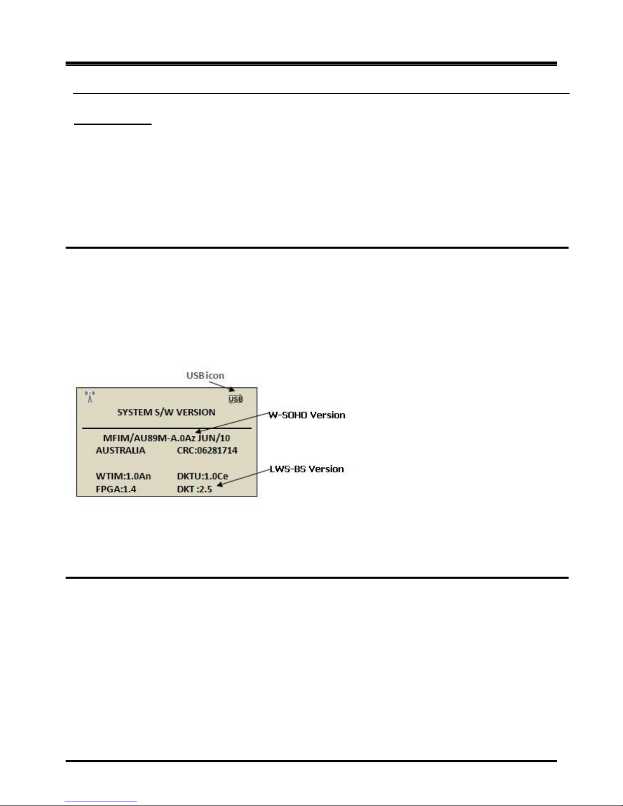
OptiCon Micro
Installation and Operation Manual
69
Operation
To change IP settings:
LWS-BS station
1. Press th e [Menu] button.
2. Dial 4 6.
3. Change IP information.
4. Press [Save] soft button.
3.30 Software Upgrade
Description
The OPTICON MICRO system and LWS-BS phone software can be upgraded employing the USB port
located on the bottom of the LWS-BS. The system and/or LWS-BS software file(s) must be separately
loaded on the USB memory device before insertion into the LWS-BS USB port. Two types of software files,
which are available from LG-Ericsson authorized representatives, are employed,
GS89Mxxxx for the OPTICON MICRO system ROM files and
GS89Dxxxx for the LWS-BS phone ROM files.
The xxxx above indicates the ROM file version and up to 5 different versions can be stored on the USB
device for upgrade of the OPTICON MICRO system or LWS-BS.
Operation
To view software versions
1. Press the [Menu] button.
2. Press 4 4
To upgrade System, at the LWS-BS:
1. Insert the USB memory device with the ROM files in the USB port on the bottom of the LWS-BS.
2. Press the [Menu] button.
3. Press 4 5 1.
4. Select the desired System ROM file (GS89Mxxxx.rom).
5. Press the [SAVE] soft button and wait the upgrade result.
6. After Upgrade success, press the [Reset] soft button to restart the system and load the upgraded
software to the OPTICON MICRO operational memory.
Page 76

OptiCon Micro
Installation and Operation Manual
70
To upgrade LWS-BS phone at the LWS-BS:
1. Insert the USB memory device with the ROM files in the USB port on the bottom of the LWS-BS.
2. Press the [Menu] button.
3. Press 4 5 2.
4. Select the desired LWS-BS station ROM file (GS89Dxxxx.rom).
5. Press the [SAVE] soft button and wait the upgrade result.
3.31 Database management
Description
From the DB Management menu, the database of the OPTICON MICRO system can be initialized, stored
as a backup copy on a USB device, or loaded to the system from a USB device. Note that the Voice mail
messages cannot be backed up or restored.
3.31.1 Initialize Database
Description
When desired the OPTICON MICRO system database can be initialized from the LWS-BS.
Operation
To initialize the OPTICON MICRO database to default values from the LWS-BS,
1. Press the [Menu] button.
2. Press 4 3 1.
3. Press the [SAVE] soft button and wait for the initialization process to complete.
3.31.2 Database backup
Description
A USB memory device can be connected to the LWS-BS and the database copied to the device as a
backup copy.
Operation
To backup the database to a USB device from the LWS-BS,
1. Insert a USB memory device to the USB port on the bottom of the LWS-BS
2. Press the [Menu] button.
3. Press 4 3 2.
4. Press 1 to backup the database.
Conditions
Page 77

OptiCon Micro
Installation and Operation Manual
71
1. The backup function does not copy (backup) the Voice messages in the OPTICON MICRO
system.
3.31.3 Database Restore
Description
A USB device that has a copy of the OPTICON MICRO database can be used to recover or copy the
database to a OPTICON MICRO system.
Operation
To restore DB:
LWS-BS station
1. Insert a USB memory device with a database to the USB port on the bottom of the LWS-BS.
2. Press the [Menu] button.
3. Press 4 3 3.
4. Press 1 to restore the database.
Conditions
1. After the database is copied from the USB device to the OPTICON MICRO memory, the
system automatically will restart to load the database to operational memory.
2. The backup function does not copy (backup) the Voice messages in the OPTICON MICRO
system.
3.32 Feature Codes
Description
User can access Feature Code unlocking several functions.
Feature codes
Feature
code
Remark
Country code
*27
Telkom
Intercom Call
100-108
DND
553 Call Forward
554 Change VM password
559 Group Call Pickup
556
Speed Dial Code
558 Direct Call Pickup
7 & ext.no
Individual Line Access
88 XX
XX : 01 ~ 03 (Line number)
Line Access Code
0 VSF/VM access code
620 Access individual held Line
8# XX
XX : 01 ~ 03 (Line number)
Access held Line
8*
Page 78

OptiCon Micro
Installation and Operation Manual
72
Attendant code
9 Default Voicemail password
Ext.no & “*”
4. USEFUL INFORMATION
4.1 Trouble shooting
If you experience any problems with the normal use of your phone, you should first power-off
and
disconnect the base station. Then connect it and connect the power again. If the phone continues to have
problems, please check the following Table before contacting the Telkom Service centre.
PROBLEM
POSSIBLE CAUSE
SOLUTION
PROBLEM
• Check that the base is connected to the
main power source and the batteries of
the handsets are properly installed.
• If you try to make a call and the
terminal is not registered, the
display shows „Out of Range‟.
There is no dial tone.
• Is the telephone line cord
correctly plugged into the
base and telephone
socket?
• Is the Terminal registered to
the base?
• Check that the base is connected to the
main power source and the batteries of
the handsets are properly installed.
• If you try to make a call and the
terminal is not registered, the
display shows „Out of Range‟.
Cannot make or receive
calls.
• Are the Handset batteries
charged?
• If the battery symbol shows empty
then place the handset on the charger
and let it charge for a few hours.
Terminal does not ring.
• Have you set the terminal
ringer volume to „Volume
Off‟?
• You can set the ringer volume for
LWS-BS, Wireless Keyset and
Handset. Verify if the ringer volume
is set too low for you and adjust if
necessary.
Cannot link up with the
LWS-BS station.
• Is “Out of Range” display?
• The LWS-BS power cable may not be
connected.
The AC power has failed and/or the
batteries in the handsets could be low
or flat. Recharge or replace the
batteries.
• Verify if the antenna of the LWS-BS
is attached tightly. Otherwise turn it
clockwise to tighten.
• Verify you are in range of the LWS-BS.
Move closer to the base if necessary.
System Power failure.
• Are th e power cord and
plug correctly connected?
• Check all connections.
• If there is an AC power failure, you
must re-connect the AC adapter to
Page 79
OptiCon Micro
Installation and Operation Manual
73
turn-on the system again.
SYSTEM ADMIN PASSWORD: Should you set an ADMIN Password via Menu item 4, 1 on the LWS-BS
menu, it is advised that you record this password somewhere safe because should you forget this
password a qualified technician is required to reset the password.
For convenience, you may record this password in the space provided below.
SYSTEM ADMIN PASSWORD
Note:
 Loading...