

Telkom Mega 200VWR Quick Start Manual

Mega 200
Mega 200V
Mega 200Mega 200
Quick Start Guide
VWR
WR
VV
WRWR

Mega 200VWR
Package Content: ........................................................................................................................ 2
The Front LEDs ........................................................................................................................... 3
The Rear Ports............................................................................................................................. 4
Getting Started: ............................................................................................................................5
Installation & Setup: (Windows XP or Windows 2000) .............................................................6
Hardware Installation: ...........................................................................................................6
Software Installation: ............................................................................................................6
Setting up VoIP accounts on your Mega 200VWR:....................................................................10
Getting Started using a wireless connection: .............................................................................12
Troubleshooting: ........................................................................................................................ 13
Product Support and Contact Information.................................................................................. 15
1
TLK/200VWR-v1.0-060928
Mega 200VWR
This Quick start guide describes a basic installation. For
Warning
Using
instructions on configuring an advanced setup, please
refer to the on-line manual available on the enclosed CD.
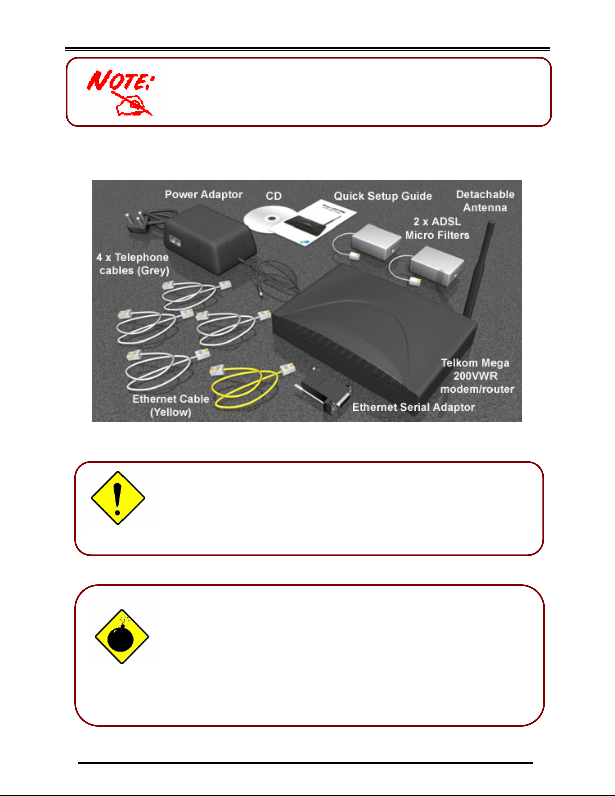
Package Content:
Attention
Place the Mega 200VWR on a stable surface.
Only use the power adapter that comes with the package.
a different voltage rating power adaptor may damage the router.
Do not use the Mega 200VWR in high humidity or high
temperature rooms and/or surroundings. I.e. Kitchens.
Do not open or try to repair the Mega 200VWR yourself.
If the Mega 200VWR gets too hot, turn off the power immediately
and contact technical support on 0860 2C HELP (0860 22 43 57)
TLK/200VWR-v1.0-060928
2
Mega 200VWR
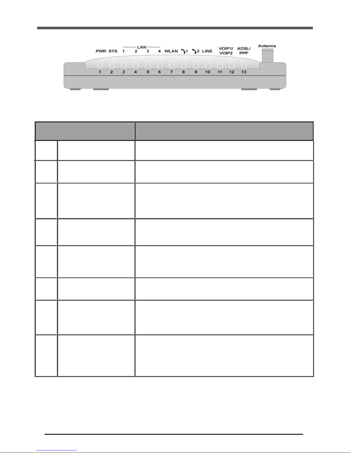
The Front LEDs
LED Meaning
1 PWR Lit when power is ON.
2 SYS Lit when the system is ready.
LAN Port
3 – 6
1X — 4X
(RJ-45 connector)
7 WLAN
Phone
8 – 9
1X — 2X
(RJ-11 connector)
10 LINE
12
VoIP Port
1X — 2X
(RJ-11 connector)
13 ADSL/PPP
Lit when connected to an Ethernet device.
Green for 100Mbps; Orange for 10Mbps.
Blinking when data is Transmitted / Received.
Lit green when the wireless connection is established.
Flashes when sending/receiving data.
Lit green when the phone is off-hook.
Lit when the inbound and outbound calls transmitted through
PSTN.
Lit when the SIP Registration is OK.
Green for Phone 1; Orange for Phone 2.
Lit Green when successfully connected to an ADSL DSLAM
(“linesync”).
Lit Orange when there is a PPP connection.
3
TLK/200VWR-v1.0-060928
Mega 200VWR
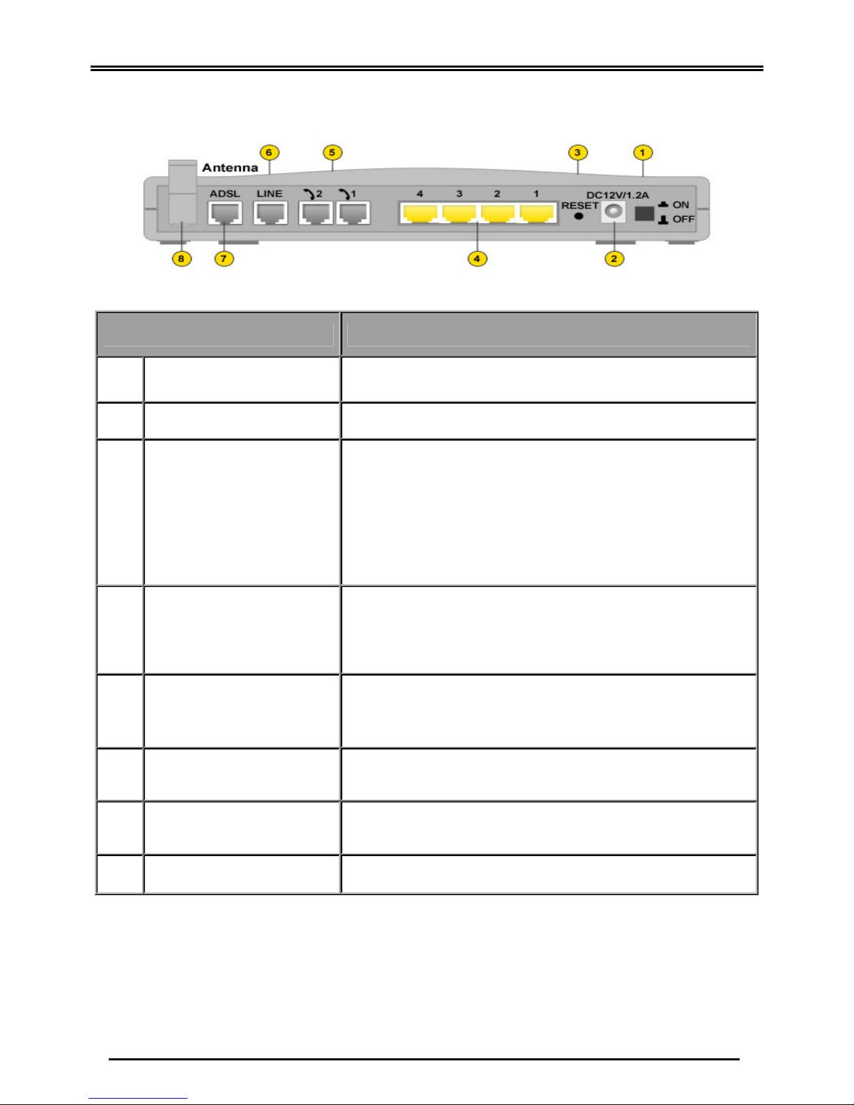
The Rear Ports
Power Switch
1
PWR
2
3 RESET
LAN
4
1X — 4X
(RJ-45 connector)
Port Meaning
Power ON/OFF switch
Connect the supplied power adapter to this jack.
After the device is powered on, press it to reset the device
or restore to factory default settings.
1-3 seconds: reset the device
8 seconds above: restore to factory default settings (this is
used when you can not login to the router, e.g. forgot the
administrative password).
Connect a UTP Ethernet cable (Cat-5 or Cat-5e) (yellow)
to one of the four LAN ports when connecting to a PC or
an office/home network of 10Mbps or 100Mbps.
Phone
1X ─ 2X
5
(RJ-11 connector)
LINE
6
ADSL
7
Antenna Connect the detachable antenna to this port.
8
Connect RJ-11 (“telephone”) cable (grey) to this port when
connecting to an analog phone set.
Connect RJ-11 (“telephone”) cable (grey) to this port when
connecting to the telephone wall jack.
Connect the supplied RJ-11 (“telephone”) cable (grey) to
this port when connecting to the ADSL/telephone network.
TLK/200VWR-v1.0-060928
4
 Loading...