

Page 1

TinyOne Plus 868MHz Terminal User
Guide
1vv0300826 Rev.3 – 14/01/2011
Page 2
TinyOne Plus 868MHz Terminal User Guide
Reproduction forbidden without Telit Communications S.p.A. written authorization - All Rights Reserved page 2 of 47
1vv0300826 Rev.3 – 14/01/2011
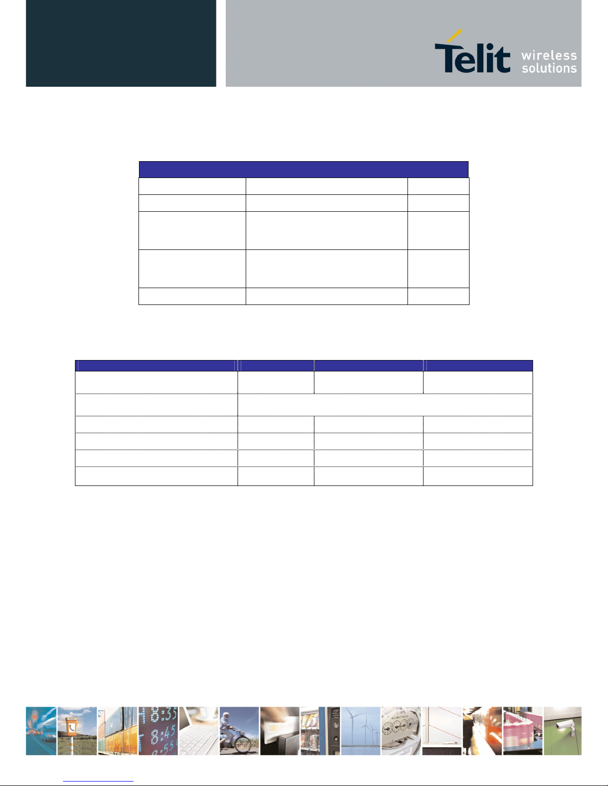
This document is related to the following product :
Page 3

TinyOne Plus 868MHz Terminal User Guide
Reproduction forbidden without Telit Communications S.p.A. written authorization - All Rights Reserved page 3 of 47
1vv0300826 Rev.3 – 14/01/2011
DISCLAIMER
The information contained in this document is the proprietary information of Telit Communications S.p.A.
and its affiliates (“TELIT”). The contents are confidential and any disclosure to persons other than the
officers, employees, agents or subcontractors of the owner or licensee of this document, without the prior
written consent of Telit, is strictly prohibited.
Telit makes every effort to ensure the quality of the information it makes available. Notwithstanding the
foregoing, Telit does not make any warranty as to the information contained herein, and does not accept
any liability for any injury, loss or damage of any kind incurred by use of or reliance upon the information.
Telit disclaims any and all responsibility for the application of the devices characterized in this document,
and notes that the application of the device must comply with the safety standards of the applicable
country, and where applicable, with the relevant wiring rules.
Telit reserves the right to make modifications, additions and deletions to this document due to
typographical errors, inaccurate information, or improvements to programs and/or equipment at any time
and without notice. Such changes will, nevertheless be incorporated into new editions of this document.
Copyright: Transmittal, reproduction, dissemination and/or editing of this document as well as utilization
of its contents and communication thereof to others without express authorization are prohibited.
Offenders will be held liable for payment of damages. All rights are reserved.
© Copyright Telit RF Technologies 2010.
Page 4

TinyOne Plus 868MHz Terminal User Guide
Reproduction forbidden without Telit Communications S.p.A. written authorization - All Rights Reserved page 4 of 47
1vv0300826 Rev.3 – 14/01/2011
CONTENTS
CHAPTER I. INTRODUCTION .....................................................................................................................................5
I.1. AIM OF THE DOCUMENT.................................................................................................................................................................................... 5
I.2. REFERENCE DOCUMENTS ................................................................................................................................................................................. 5
I.3. DOCUMENT CHANGE LOG ................................................................................................................................................................................. 6
I.4. GLOSSARY ...................................................................................................................................................................................................... 7
CHAPTER II. GENERAL CHARACTERISTICS ...........................................................................................................8
II.1. GENERAL REQUIREMENTS .............................................................................................................................................................................. 8
II.2. TEMPERATURE CHARACTERISTICS ................................................................................................................................................................ 10
II.3. MECHANICAL CHARACTERISTICS ................................................................................................................................................................... 10
II.4. DC CHARACTERISTICS ................................................................................................................................................................................. 11
II.5. TIMING CHARACTERISTICS............................................................................................................................................................................ 11
II.6. FUNCTIONAL CHARACTERISTICS .................................................................................................................................................................... 12
II.7. DIGITAL CHARACTERISTICS........................................................................................................................................................................... 14
II.8. ORDERING INFORMATION .............................................................................................................................................................................. 15
CHAPTER III. MECHANICS AND CONNECTION.....................................................................................................16
III.1. MECHANICAL CHARACTERISTICS ................................................................................................................................................................. 16
III.2. CONNECTIONS ............................................................................................................................................................................................ 17
III.3. CABLES DESCRIPTION FOR IP67 CASING ..................................................................................................................................................... 18
CHAPTER IV. STANDARD FIRMWARE : DESCRIPTION OF THE FUNCTIONALITY............................................20
IV.1. CONFIGURATION MODE ............................................................................................................................................................................... 21
IV.2. OPERATING MODE....................................................................................................................................................................................... 23
IV.3. REGISTERS DETAILED USE .......................................................................................................................................................................... 25
IV.4. REGISTERS LIST .......................................................................................................................................................................................... 34
IV.5. CONFIGURATION EXAMPLE .......................................................................................................................................................................... 38
IV.6. MODEMS REFLASHING ................................................................................................................................................................................. 39
IV.7. CONFIGURATION AND DOWNLOAD OVER THE AIR (DOTA) ............................................................................................................................ 40
CHAPTER V. ANNEXES ............................................................................................................................................41
V.1. MODEMS’ INSTALLATION: PRINCIPLES AND CAUTIONS ..................................................................................................................................... 41
V.2. CONNECTION TO A RS422 OR RS485 INTERFACE .......................................................................................................................................... 42
V.3. ETSI 300 220-3 VERSION 1.3.1 STANDARDS (SUMMARY) ............................................................................................................................... 43
V.4. EXAMPLES OF PROPAGATION ATTENUATION ................................................................................................................................................... 46
V.5. DECLARATIONS OF COMPLIANCE ................................................................................................................................................................... 47
Page 5

TinyOne Plus 868MHz Terminal User Guide
Reproduction forbidden without Telit Communications S.p.A. written authorization - All Rights Reserved page 5 of 47
1vv0300826 Rev.3 – 14/01/2011
CHAPTER I. INTRODUCTION
I.1. Aim of the Document
The aim of this document is to present the features and the application of M868-TinyPlus radio terminal. The
characteristics will be described within three distinct chapters:
- "General characteristics" describes the electrical and mechanical characteristics.
- "Mechanics and connections" details the casing, connector, cabling and power supply.
- "Functionalities" lists the operating modes, registers and their use.
I.2. Reference documents
[1] EN 300 220-2 v2.1.2
ETSI Standards for SRD , June 2007
[2] ERC Rec 70-03
ERC Recommendation for SRD, June 2009
[3] 2002/95/EC
Directive of the European Parliament and of the Council, 27 January
2003
[4] TinyTools : User Manual
1vv0300824_Tiny Tools User Guide
[5] Mesh Lite : User Manual
1vv0300819_M_ONE Protocol Stack User Guide
Page 6
TinyOne Plus 868MHz Terminal User Guide
Reproduction forbidden without Telit Communications S.p.A. written authorization - All Rights Reserved page 6 of 47
1vv0300826 Rev.3 – 14/01/2011
I.3. Document change log
RReevviissiioonn DDaattee
CChhaannggeess
ISSUE # 0 29/04/09 First Release
ISSUE # 1 21/06/10 Updated: reference documents table, ERC 70-30 recommendation table
Added description of the behavior for internal LEDs
ISSUE # 2 14/09/10 Removed Terminal variant with fixed antenna
ISSUE # 3 14/01/11 Updated paragraph 3.1, Removed USB dongle
Page 7

TinyOne Plus 868MHz Terminal User Guide
Reproduction forbidden without Telit Communications S.p.A. written authorization - All Rights Reserved page 7 of 47
1vv0300826 Rev.3 – 14/01/2011
I.4. Glossary
ACP
Adjacent Channel Power
BER
Bit Error Rate
Bits/s
Bits per second (1000 bits/s = 1Kbps)
CER
Character Error Rate
dBm
Power level in decibel milliwatt (10 log (P/1mW))
EMC
Electro Magnetic Compatibility
EPROM
Electrical Programmable Read Only Memory
ETR
ETSI Technical Report
ETSI
European Telecommunication Standard Institute
FM
Frequency Modulation
FSK
Audio Frequency Shift Keying
GFSK
Gaussian Frequency Shift Keying
GMSK
Gaussian Minimum Shift Keying
IF
Intermediary Frequency
ISM
Industrial, Scientific and Medical
kbps
kilobits/s
LBT
Listen Before Talk
LNA
Low Noise Amplifier
MHz
Mega Hertz (1 MHz = 1000 kHz)
PLL
Phase Lock Loop
PROM
Programmable Read Only Memory
NRZ
Non return to Zero
RF
Radio Frequency
RoHS
Restriction of Hazardous Substances
RSSI
Receive Strength Signal Indicator
Rx
Reception
SRD
Short Range Device
Tx
Transmission
SMD
Surface Mounted Device
VCO
Voltage Controlled Oscillator
VCTCXO
Voltage Controlled and Temperature Compensated Crystal Oscillator
Page 8
TinyOne Plus 868MHz Terminal User Guide
Reproduction forbidden without Telit Communications S.p.A. written authorization - All Rights Reserved page 8 of 47
1vv0300826 Rev.3 – 14/01/2011
CHAPTER II. GENERAL CHARACTERISTICS
II.1. General Requirements
The M868-TinyPlus terminal is a multi channel radio modem, delivering up to 25 mW in the 868 MHz ISM band
(unlicensed frequency band).
It allows ‘point-to-point’, `multipoint’ or ‘mesh’ functioning modes.
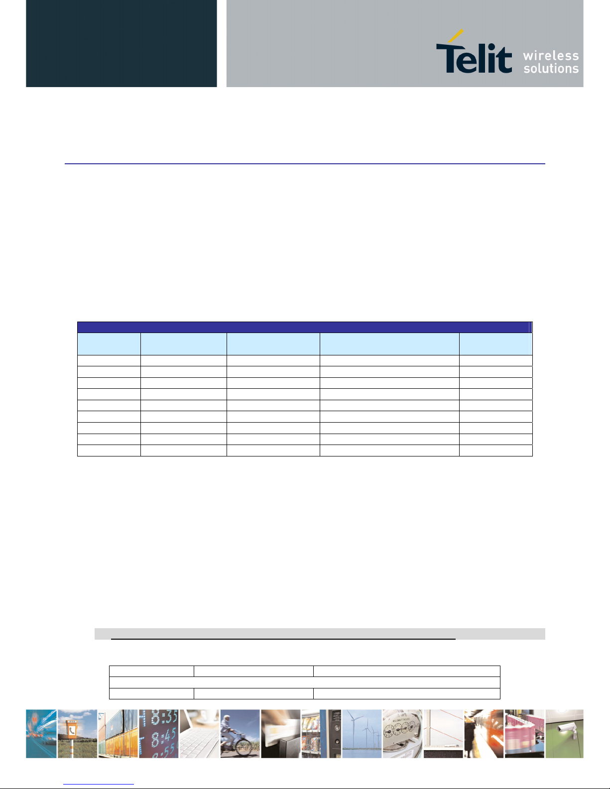
The “ERC recommendation 70-03” describes the different usable sub-bands in the 868 MHz license free band, in
terms of bandwidth, maximum power, duty cycle and channel spacing. It gives the following limitations :
ERC recommendation 70-03
Band Frequency band
(MHz)
Maximum radiated
power (mW)
Channel spacing
(kHz)
Duty cycle
(%)
Annex1 g1 868.0 – 868.6 25 No channel spacing specified 1
Annex7 a 868.6 - 868.7 10 25 1
Annex1 g2 868.7 - 869.2 25 No channel spacing specified 0,1
Annex7 d 869.2 – 869.25 10 25 0.1
Annex7 b 869.25 – 869.3 10 25 0.1
Annex7 e 869.3 – 869.4 10 25 1
Annex1 g3 869.4 - 869.65 500 25 (for 1 or more channels) 10
Annex7 c 869.65 – 869.7 25 25 10
Annex1 g4 869.7 – 870.0 5 No channel spacing specified 100
This band is free to use but the terminal and the user must respect some limitations. Most of these restrictions are
integrated in the conception of the terminal, except the duty cycle. For example, the 869.400 to 869.650 MHz band
is limited to a 10% duty cycle. This means that each terminal is limited to a total transmit time of 6 minutes per
hour. It is the responsibility of the user to respect the duty cycle.
Furthermore, the terminal complies with the ETSI 300-220 (specific for SRD). The main requirements are described
in Appendix 1.
Finally, the terminal complies with the new European Directive 2002/95/EC concerning the Restrictive Usage of
Hazardous Substances (RoHS).
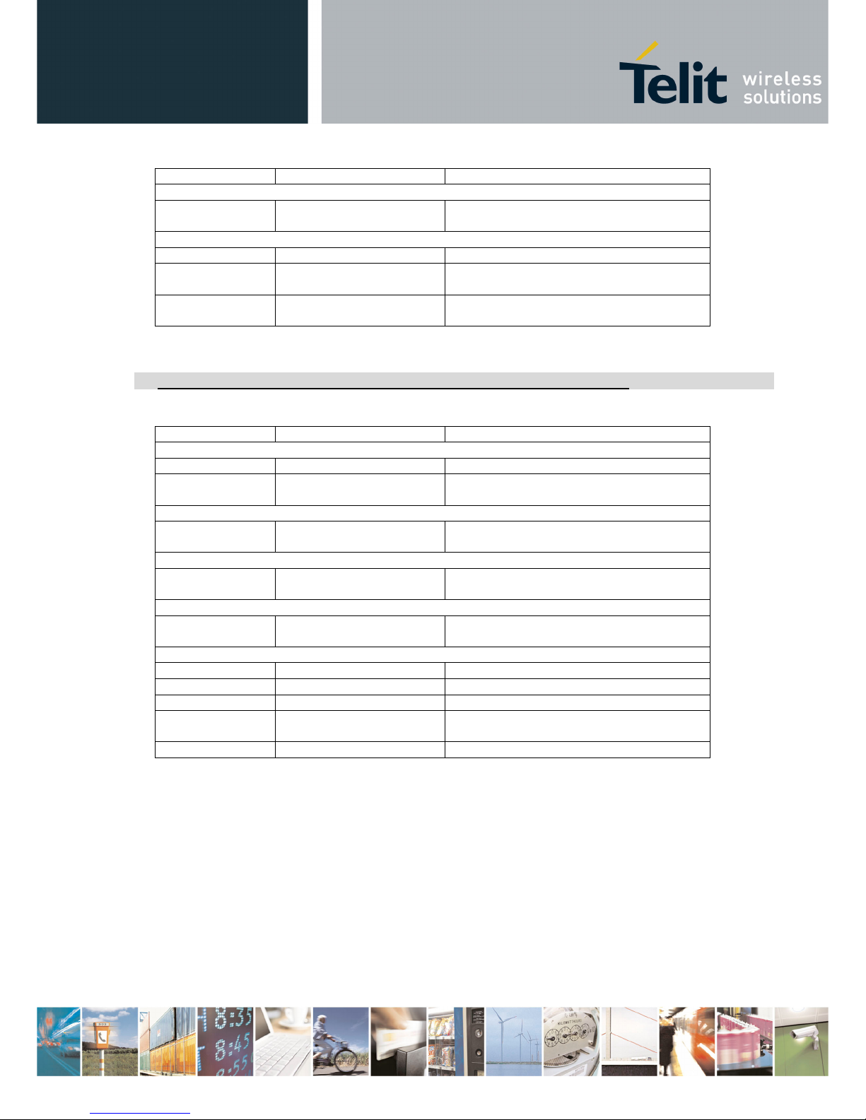
National Restrictions for non specific SR devices Annex 1 band g1-g4:
Country Restriction Reason/Remark
Band G1
Russian No info
Page 9
TinyOne Plus 868MHz Terminal User Guide
Reproduction forbidden without Telit Communications S.p.A. written authorization - All Rights Reserved page 9 of 47
1vv0300826 Rev.3 – 14/01/2011
Federation
Band G3
Russian
Federation
No info
Band G4
Finland Audio not allowed
Hungary
Audio applications are
excluded
Russian
Federation
No info
National Restrictions for non specific SR devices Annex 7 band a-e:
Country Restriction Reason/Remark
Band A
France Duty cycle limited to 0.1%
Russian
Federation
Limited implementation 868-868.2 MHz
Band B
Russian
Federation
No info
Band C
Russian
Federation
No info
Band D
Russian
Federation
No info
Band E
France Not implemented
Greece Not implemented
Macedonia Not implemented Planned
Russian
Federation
No info
Sweden Not implemented
Page 10

TinyOne Plus 868MHz Terminal User Guide
Reproduction forbidden without Telit Communications S.p.A. written authorization - All Rights Reserved page 10 of 47
1vv0300826 Rev.3 – 14/01/2011
II.2. Temperature Characteristics
Minimum Typical Maximum Unit
Operating
Temperature - 40 25 + 85 °C
Relative humidity 20 75 %
Storage
Temperature - 40 25 + 85 °C
Relative humidity 0 95 %
II.3. Mechanical Characteristics
Mechanical characteristics
Characteristics IP67 casing Unit
Material Aluminium
Connectors
Terminal blocks inside the casing.
Exit through cable gland
-
Dimensions
117 x 64 x 40
(without antenna)
mm
3
Weight 300 g
Antenna length :
• Removable antenna
93
mm
LEDs
No LEDs are available
Page 11
TinyOne Plus 868MHz Terminal User Guide
Reproduction forbidden without Telit Communications S.p.A. written authorization - All Rights Reserved page 11 of 47
1vv0300826 Rev.3 – 14/01/2011
II.4. DC Characteristics
DC characteristics
Characteristics IP67 casing Unit
Power Supply +6 to +40 V
Transmission
consumption
(@25mW)
@6V : 60
@12V : 35
@40V : 15
mA
Reception
consumption
@6V : 30
@12V : 25
@40V : 10
mA
Stand-by consumption 70 µA
II.5. Timing Characteristics
Characteristics Min. Typ. Max.
Power Up Sequence :
- 135 ms 150 ms
Stand by :
Enter in Hard Stand-by :
- 700 µs 900 µs
Enter in Serial Stand-by :
- 3.2 ms -
Wake Up from Hard Stand-by :
- 2.85 ms 3.0 ms
Wake Up from Serial Stand-by :
- 5.5 ms -
Page 12
TinyOne Plus 868MHz Terminal User Guide
Reproduction forbidden without Telit Communications S.p.A. written authorization - All Rights Reserved page 12 of 47
1vv0300826 Rev.3 – 14/01/2011
II.6. Functional characteristics
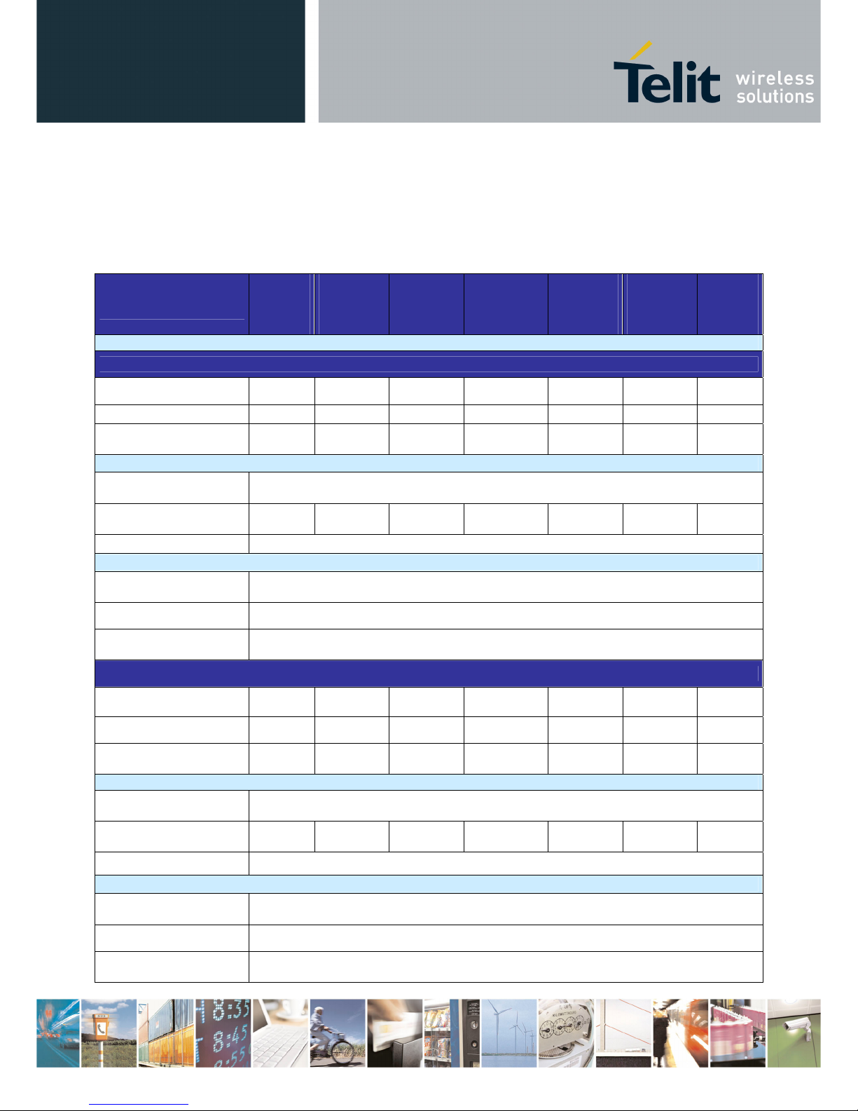
The M868-tinyPlus functional characteristics depend on the RF data rate. 4 data rates are available : 4.8,
9.6, 19.2 or 38.4 kbps.
Frequency Sub-Band
(MHz)
Band g1
868-
868.6
Band 7a
868.6-
868.7
Band g2
868.7-
869.2
Band 7d, 7b
& 7e
869.2-869.4
Band g3
869.4-
869.65
Band 7c
869.65-
869.7
Band g4
869.7870
Global
RF data rate : 4.8 kbps
Channel number
12 4 10 2, 2 & 4 10 2 6
Channel width (kHz)
50 25 50 25 25 25 50
Frequency
Channel 0
868.025 868.6125 868.725 869.2125 869.4125 869.6625 869.725
Transmission
Output Power
(under 50 Ω)
4 levels selectable by software (see Hayes command ATS202)
Max output power
(mW)
25 10 25 10 25 25 5
Modulation
GFSK with ±5 kHz deviation
Reception
Sensitivity
for CER<10
-3
-105 dBm (± 1dB) under 50Ω
Remaining CER
< 1.10
-6
Saturation
for CER<10
-3
Up to -5 dBm under 50Ω
RF data rate : 9.6 kbps
Channel number
12 4 10 2, 2 & 4 10 2 6
Channel width (kHz)
50 25 50 25 25 25 50
Frequency
Channel 0
868.025 868.6125 868.725 869.2125 869.4125 869.6625 869.725
Transmission
Output Power
(under 50 Ω)
4 levels selectable by software (see Hayes command ATS202)
Max output power
(mW)
25 10 25 10 10 10 5
Modulation
GFSK with ±10 kHz deviation
Reception
Sensitivity
for CER<10
-3
-103 dBm (± 1dB) under 50 Ω
Remaining CER
< 1.10
-6
Saturation
for CER<10
-3
Up to -5 dBm under 50
Ω
Page 13
TinyOne Plus 868MHz Terminal User Guide
Reproduction forbidden without Telit Communications S.p.A. written authorization - All Rights Reserved page 13 of 47
1vv0300826 Rev.3 – 14/01/2011
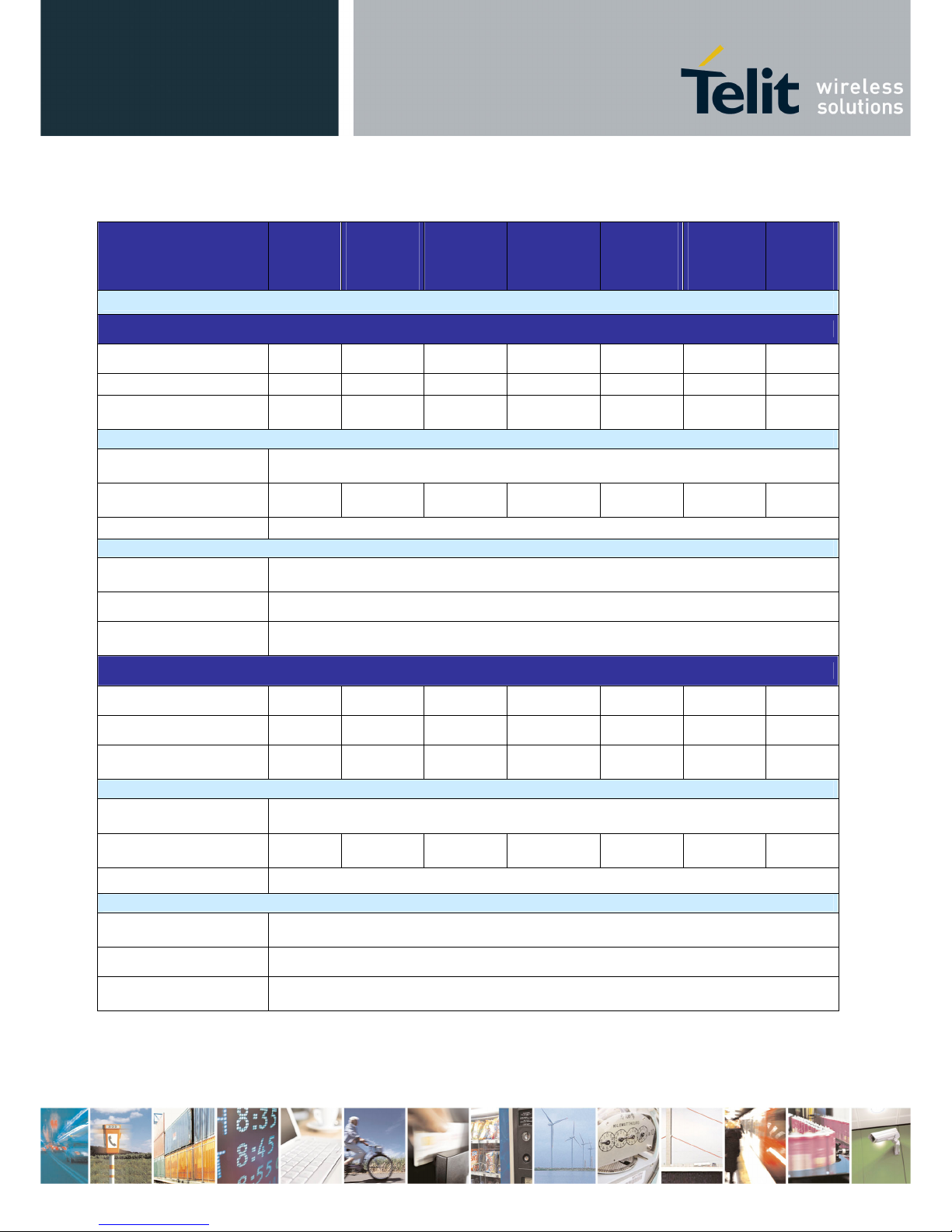
Frequency Sub-Band
(MHz)
Band 1f
868-
868.6
Band 7a
868.6-
868.7
Band 1g
868.7-
869.2
Band 7d, 7b
& 1h
869.2-869.4
Band 1i
869.4-
869.65
Band 7c
869.65-
869.7
Band 1k
869.7870
Global
RF data rate : 19.2 kbps
Channel number
6 None 5 None 1 None
3
Channel width (kHz)
100 - 100 - 100 - 100
Frequency
Channel 0
868.05 - 868,75 - 869,525 - 869,75
Transmission
Output Power
(under 50 Ω)
4 levels selectable by software (see Hayes command ATS202)
Max output power
(mW)
25 25 25 5
Modulation
GFSK with ±20 kHz deviation
Reception
Sensitivity
for CER<10
-3
-102 dBm (± 1dB) under 50
Ω
Remaining CER
< 1.10
-6
Saturation
for CER<10
-3
Up to -5 dBm under 50
Ω
Radio Bit Rate : 38.4 kbps
Channel number
3 None 2 None 1 None 2
Channel width (kHz)
200 - 200 - 200 - 200
Frequency
Channel
0
868,1 - 868,85 - 869,525 - 869,775
Transmission
Output Power
(under 50 Ω)
4 levels selectable by software (see Hayes command ATS202)
Max output power
(mW)
25 25 25 5
Modulation
GFSK with ±40 kHz deviation
Reception
Sensitivity
for CER<10
-3
-100 dBm (± 1dB) under 50
Ω
Remaining CER
< 1.10
-6
Saturation
for CER<10
-3
Up to -5 dBm under 50
Ω
Page 14
TinyOne Plus 868MHz Terminal User Guide
Reproduction forbidden without Telit Communications S.p.A. written authorization - All Rights Reserved page 14 of 47
1vv0300826 Rev.3 – 14/01/2011
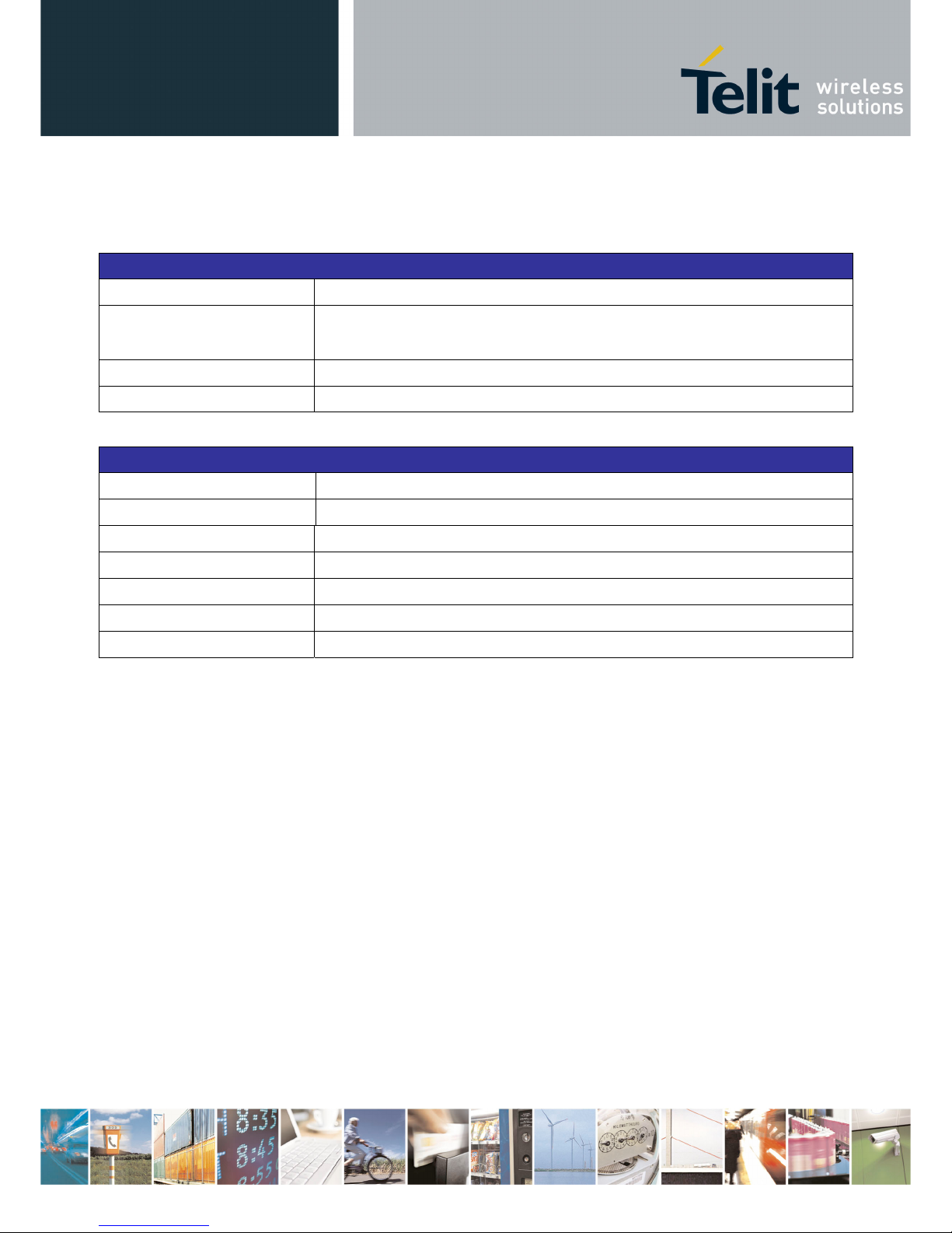
II.7. Digital Characteristics
Digital characteristics
Micro-controller
Micro-controller RISC 8 bits with Flash memory
Programming
• Through serial link
• Through the air (Download Over The Air)
RAM memory
2 Kbytes
Flash memory
16 Kbytes
Serial link characteristics
Characteristics IP67 casing
Serial link type
RS232 / 485 / 422
Serial speed
1200 to 115200 bits/s
Data bits
8
Stop bits
1 or 2
Parity
None, Even, Odd
Flow control type
None, Hardware (RTS/CTS), Software (Xon/Xoff)
Page 15
TinyOne Plus 868MHz Terminal User Guide
Reproduction forbidden without Telit Communications S.p.A. written authorization - All Rights Reserved page 15 of 47
1vv0300826 Rev.3 – 14/01/2011
II.8. Ordering information
Select the desired options from the list below to identify the appropriate Telit part number you need.
Antenna option
RA: Removable Antenna
Casing
67: Metallic IP67
M 868 – tinyPLUS / 40 – XX – XX – P
Page 16

TinyOne Plus 868MHz Terminal User Guide
Reproduction forbidden without Telit Communications S.p.A. written authorization - All Rights Reserved page 16 of 47
1vv0300826 Rev.3 – 14/01/2011
CHAPTER III. MECHANICS AND CONNECTION
III.1. Mechanical Characteristics
• Mechanical Drawings for IP67 casing
117mm
64mm
40mm
Page 17

TinyOne Plus 868MHz Terminal User Guide
Reproduction forbidden without Telit Communications S.p.A. written authorization - All Rights Reserved page 17 of 47
1vv0300826 Rev.3 – 14/01/2011
III.2. Connections
• IP67 casing
The terminal will communicate with the host through a cable connected to terminal blocks on the mother board
inside the casing (orange part on the following drawing) :
¾ TxD, RxD: Serial link signals in RS232 format. TxD is for the data going out
of the Modem
while RxD is for the data coming into
the Modem. The logic '1' is represented by
signal between –3 and –15V.
¾ DTR: Stand-By signal into the Modem. Switches the Modem in Low-Power Mode ('1', -
15V to -3V) or in Normal Mode ('0', +3V to +15V).
¾ RS232/485: Used with the S215 Register, selects the type of serial link : open for RS232
(default, internal pull up 100 Kohms), GND for RS422 or RS485. Can be also made
by RS232/485 switch.
¾ A, B, Y, Z : RS422/RS485 signals.
For RS422 use A (or Rx+), B (or Rx-), Y (or Tx+) and Z (or Tx-).
For RS485, use only A (or D+) and B (or D-).
¾ CTS: Clear To Send: signal into the Modem. Indicates if the Modem can send serial data
to the User (Active on ‘0’, +3V to +15V) or not (Inactive on ‘1’, -15V to -3V).
Page 18

TinyOne Plus 868MHz Terminal User Guide
Reproduction forbidden without Telit Communications S.p.A. written authorization - All Rights Reserved page 18 of 47
1vv0300826 Rev.3 – 14/01/2011
¾ RTS: Request To Send: signal going out of the Modem. Indicates that the user can
transmit serial data (Active on ‘0’, +3V to +15V) or not (Inactive on ‘1’, -15V to -3V).
This signal switches when the serial reception buffer's filling rate reaches a
programmable threshold (S218) or when the user finished transmitting serial data
(out on Time-Out).
¾ 6-40V : 6 to 40 VDC power supply. There is no internal ON/OFF switch for the power
supply. The switch off capability should be external.
Internal LED:
- Green: informs about association (blinks when searching for association, stays ON when associated)
- Red: indicates data reception (blinks each 5 seconds when receiving beacon)
Note: In case of the S-One stack green LED indicated transmission.
III.3. Cables Description for IP67 Casing
The associated cable is connected to the terminal blocks of the mother board and goes out of the modem through
a cable gland. The cable must be shielded and have an external diameter between 3.5 and 7mm. The conductors
must have a cross section of 0.22mm² (24AWG).
Possible cable references:
Supplier Reference Description
NEXANS
SMBL07x0.22
7 conductors
ALPHA WIRE
5118C
8 conductors
TELIT
205.000.094
1 meter serial cable with subD-9 connector for RS232
and 2 points connector for power supply
• Case of RS-232
Connector
(8 points)
Name
Modem Side
Color
Name
PC/Automate Side
Connector
Sub-D
(9 points)
1 TxD (Transmit Data) Blue RxD (Receive Data) 2
2 RxD (Receive Data) White TxD (Transmit Data) 3
3 CTS (Clear To Send) Brown RTS (Request To Send) 7
4 RTS (Request To Send) Yellow CTS (Clear To Send) 8
5 DTR Green DTR 4
6 RS232/422-485 Orange
Open
Page 19

TinyOne Plus 868MHz Terminal User Guide
Reproduction forbidden without Telit Communications S.p.A. written authorization - All Rights Reserved page 19 of 47
1vv0300826 Rev.3 – 14/01/2011
7 Gnd (ground) Black Gnd (ground) 5
8 Vcc (6 to 40v) Red Vcc (6to 40v)
• Case of RS-422:
Connector
(8 points)
Name
Modem Side
Color
Name
Automate Side
1 Z or Tx- (Transmit Data) Blue B or Rx- (Receive Data)
2 A or Rx+ (Receive Data) White Z or Tx+ (Transmit Data)
3 B or Rx- (Receive Data) Brown Y or Tx- (Transmit Data)
4 Y or Tx+ (Transmit Data) Yellow A or Rx+ (Receive Data)
5 DTR Green Open
6 RS232/422-485 Orange
GND (and S215=1)
7 Gnd (ground) Black Gnd (ground)
8 Vcc (6 to 40v) Red Vcc (6 to 40v)
• Case of the RS-485
Connector
(8 points)
Name
Modem Side
Color
Name
Automate Side
1 B (Data-) Blue B (Data-)
2 open White Open
3 open Brown Open
4 A (Data+) Yellow A (Data+)
5 DTR Green Open
6 RS232/422-485 Orange
GND (and S215=2)
7 Gnd (ground) Black Gnd (ground)
8 Vcc (6 to 40v) Red Vcc (6 to 40v)
Page 20

TinyOne Plus 868MHz Terminal User Guide
Reproduction forbidden without Telit Communications S.p.A. written authorization - All Rights Reserved page 20 of 47
1vv0300826 Rev.3 – 14/01/2011
CHAPTER IV.
STANDARD FIRMWARE : DESCRIPTION OF THE FUNCTIONALITY
Telit terminals and boards are provided with an embedded software which allows to choose between different
communication protocols and to play on numerous parameters.
M868-TinyPlus terminal is available with the following firmwares :
- S-ONE protocol stack:
o Standard firmware.; working in transparent or address secured mode..
- M-ONE protocol stack:
o Mesh Lite firmware, allowing mesh networking : refer to dedicated manual ([5]) for
detailed explanation.
This Chapter is dedicated to the S-ONE protocol stack.
NOTE: The available memory space on the terminal is limited and for this reason Standard and Telemetry firmware
are available in the separate installation packages.
There are 2 different modes available for S-ONE protocol stack that are described in following paragraphs :
- The configuration mode which allows to parameter the terminal. It is set through the use of Hayes
commands sent on the serial link.
- The operating mode which is the functional use for data transmission
Page 21

TinyOne Plus 868MHz Terminal User Guide
Reproduction forbidden without Telit Communications S.p.A. written authorization - All Rights Reserved page 21 of 47
1vv0300826 Rev.3 – 14/01/2011
IV.1. Configuration Mode
Hayes or 'AT' commands complies with Hayes protocol used in PSTN terminal standards. This ‘AT’ protocol or
Hayes mode is used to configure the terminal parameters, based on the following principles:
- A data frame always begins with the two ASCII ’AT’ characters, standing for ‘ATtention’
- Commands are coded over one or several characters and may include additional data
- A given command always ends up with a <CR> Carriage Return
A T Command Additional data <CR>
Note:
The delay between 2 characters of the same command must be less than 10 seconds
The only exception to this data-framing rule is the switching command from the operating/communication mode to
‘AT Mode’. In this case only, the escape code (‘+++’) must be started and followed by a silent time at least equal to
the serial time out. In this case only <AT> and <CR> shall not be used.
Below is the complete list of the ‘AT’ commands available on the M868-TinyPlus terminal.
Command Description
+++
Hayes Mode Activation
‘+++’ command gives an instant access to the terminal’s parameters
configuration mode (Hayes or AT mode), whatever the current
operating mode in process might be.
‘+++’ command should be entered as one string, i.e. it should not be
preceded by ‘AT’ and followed by <CR> but two silent times which
duration is configurable via S214 register (Serial time-out). The time
between two ‘+’ must not exceed the time-out value.
Hayes mode inactivates radio functions.
ATO
Communication mode activation
‘ATO’ command gives an instant access to the terminal’s operating
mode, configured in S220 register.
‘ATO’ command is used to get out of Hayes mode.
Answer : OK or ERROR if the configuration is not complete
AT/V
Terminal’s firmware version
‘AT/V’ command displays the terminal’s firmware version number as
follows:
Version <Product>: vX.YZn
AT/S
Terminal’s registers status
‘AT/S’ command displays status of all relevant registers of the terminal
Page 22

TinyOne Plus 868MHz Terminal User Guide
Reproduction forbidden without Telit Communications S.p.A. written authorization - All Rights Reserved page 22 of 47
1vv0300826 Rev.3 – 14/01/2011
ATSn?
Register interrogation
‘ATSn?’ command displays the content of Hayes register number n
(Refer to the register description table).
Some registers are standard for every Telit terminals while others are
specific to some products.
Answer : Sn=x<CR>
ATSn=m
Register modification
‘ATSn=m’ command configures Hayes register number n with the
value m, e.g. ATS200=4<CR> enters the value ‘4’ in the register S200.
The value is automatically stored in the EEPROM memory.
Answer : OK or ERROR
ATN
RSSI interrogation
‘ATN’ command runs the received RF level measurement. This RSSI
reading is continuously displayed each second until a new character
arrives on the serial link.
4 levels are available :
- ‘0’ : received level < -87dBm
- ‘1’ : received level between -87 and -82dBm
- ‘2’ : received level between -82 and -77dBm
- ‘3’ : received level > -77dBm
ATR
Parameters reset
‘ATR’ command resets all terminal’s parameters to their default values.
Answer : OK
ATP
Stand By Activation
When serial stand by is set, the ‘ATP’ command put the terminal in
stand by mode. To wake up the terminal, send a NULL (0x00)
character.
ATBL
Switch to Bootloader
‘ATBL’ command escape from the main program and run the
bootloader. This command is useful to update the firmware by serial or
radio link. See the dedicated part for details.
Specific ‘AT’ commands have been integrated in order to make measurements in continuous mode.
These commands are stopped by the sending of a character.
Command Description
ATT0 Pure carrier transmission at center frequency
ATT1 Pure carrier transmission representing ‘0’
ATT2 Pure carrier transmission representing ‘1’
ATT3
Max modulated carrier transmission
ATT6
Min modulated carrier transmission
Note 1 : After an AT command (ended by <CR>), the serial link gives back result code, which is "OK” or "ERROR ".
Note 2 : "+++" command gives back OK.
These commands are effective after a maximum delay of 10 mS ; the back code OK indicates the good execution of the
command, and another command can be sent right after the back code OK.
Page 23

TinyOne Plus 868MHz Terminal User Guide
Reproduction forbidden without Telit Communications S.p.A. written authorization - All Rights Reserved page 23 of 47
1vv0300826 Rev.3 – 14/01/2011
IV.2. Operating Mode
There are 4 communication protocols available on the M868-TinyPlus terminal :
- Transparent mode : this is the default communication protocol of the terminal. The terminal transmits the
data transparently, without encapsulation or addressing. It acts as a half duplex wired serial link (type
RS485).
- Addressed Secured mode : it is a kind of multipoint network protocol. Each terminal can communicate with
every terminal in the same network. All the frames are addressed, checked through a CRC and
acknowledged.
- Downloader over the air : this is a specific communication protocol allowing re-flashing of remote terminal.
- Auto-repeat mode : this is a specific communication protocol in which the terminal sends back the frames it
has received (radio or serial) without echoing. It allows the user to easily test the terminal remotely.
For the classical communication protocols (Transparent and Addressed Secured), an additional functionality is
available : LBT (Listen Before Talk). It means that the transmitting terminal will scan the radio link and verify it is
free (no radio activity) before sending its data to avoid collision.
Basic Illustration of Transparent mode
Terminal N°1 Terminal N°2
Terminal N°3
1 sends ABCD
<ABCD> <ABCD>
<ABCD>
2 sends Hello
<Hello> <Hello>
<Hello>
<in blue> : data sent
<in red> : data received
Page 24

TinyOne Plus 868MHz Terminal User Guide
Reproduction forbidden without Telit Communications S.p.A. written authorization - All Rights Reserved page 24 of 47
1vv0300826 Rev.3 – 14/01/2011
Basic Illustration of Addressed Secured mode
Terminal N°1 Terminal N°2
Terminal N°3
1 sends ABCD to 2
<2=ABCD>
OK
<1=ABCD>
1 sends EFGH to 3
(with a retry)
<3=EFGH>
OK
<1=EFGH>
ACK
3 sends Hello as
Broadcast
<3=Hello>
<3=Hello>
<0=Hello>
Basic Illustration of Addressed Secured mode with LBT
Terminal N°1 Terminal N°2
Terminal N°3
1 sends ABCD to 2
(radio link free)
<2=ABCD>
OK
<1=ABCD>
1 sends EFGH to 3
(radio link not free)
<3=EFGH>
OK
<1=EFGH>
Waiting time
ACK
<in blue> : data sent
<in red> : data received
Collision or error
LBT = OK
ACK
LBT = NOK
Waiting time
LBT = OK
ACK
Page 25

TinyOne Plus 868MHz Terminal User Guide
Reproduction forbidden without Telit Communications S.p.A. written authorization - All Rights Reserved page 25 of 47
1vv0300826 Rev.3 – 14/01/2011
IV.3. Registers Detailed Use
The parameters to be configured via Hayes mode are stored in the terminal permanent memory, called S registers.
Those registers are always listed as follow:
- S20x registers correspond to the radio parameters
- S21x registers correspond to the serial parameters
- S22x registers correspond to the operating parameters
- S24x registers correspond to the stand by parameters
- S25x registers correspond to the network parameters
Radio Configuration
The Radio configuration is set via the S20x registers. Through them, you can:
ª Change radio channel : S200,
ª Change the radio baud rate : S201,
ª Change the radio Output Power : S202,
ª Modify the carrier length : S204,
ª Change Radio Frequency Sub-Band : S206.
The radio parameters are preferably set in the following order :
1. Radio baud rate : S201
This register allows changing the radio baud rate.
S201 value Radio baud rate
0 4.8 kbps
1 9.6 kbps
2 19.2 kbps
3 (default) 38.4 kbps
Page 26

TinyOne Plus 868MHz Terminal User Guide
Reproduction forbidden without Telit Communications S.p.A. written authorization - All Rights Reserved page 26 of 47
1vv0300826 Rev.3 – 14/01/2011
2. Frequency Sub-band assignment : S206
This register sets the Frequency Sub-band used for the communication.
- At 4.8 and 9.6 kbps, the terminal can use any of 9 Sub-Bands (0 to 8), starting at 868 MHz and ending at 870
MHz.
S206 value Band Frequency Sub-Band
0 1f 868-868.6 MHz
1 7a 868.6-868.7 MHz
2 1g 868.7-869.2 MHz
3 7d 869.2-869.25 MHz
4 7b 869.25-869.3 MHz
5 1h 869.3-869.4 MHz
6 1i 869.4-869.65 MHz
7 7c 869.65-869.7 MHz
8 1k 869.7-870 MHz
- At 19.2 and 38.4 kbps, the terminal is limited with 4 Sub-Bands.
S206 value Band Frequency Sub-Band
0 1f 868-868.6 MHz
2 1g 868.7-869.2 MHz
6 1i 869.4-869.65 MHz
8 1k 869.7-870 MHz
Terminals must be on the same Sub-Band to communicate. The default value for this register is S206=0
3. Radio channel : S200
This register sets the radio channel used for the communication. For example, at 38.4 kbps on Sub-Band 0, the
terminal can use any of 3 channels (0 to 2), spaced by 200 kHz.
Channel Frequency
0 868.100 MHz
1 868.300 MHz
2 868.500 MHz
Terminals must be on the same channel to communicate. The default value for this register is S200=0
If more than one group of M868-TinyPlus have to be present in the same area, each must be set to a different radio
channel to be able to communicate without interference from the other groups. Each channel must be chosen as
far as possible from the others to avoid inter channel interferences.
Page 27

TinyOne Plus 868MHz Terminal User Guide
Reproduction forbidden without Telit Communications S.p.A. written authorization - All Rights Reserved page 27 of 47
1vv0300826 Rev.3 – 14/01/2011
4. Radio Output power : S202
The default value (in bold) is set to the maximum output power authorized in each Sub-Band.
Frequency SubBand
Band g1
868-868.6
Band 7a
868.6-868.7
Band g2
868.7-869.2
Band 7d,
7b & 7e
869.2-869.4
Band g3
869.4-
869.65
Band 7c
869.65-
869.7
Band g4
869.7-870
Radio Bit Rate : 4.8 Kbps
S202 Value
0:
1:
2:
3:
1mW
3mW
8mW
25mW
0:
1:
2:
1mW
3mW
8mW
0:
1:
2:
3:
1mW
3mW
8mW
25mW
0:
1:
2:
1mW
3mW
8mW
0:
1:
2:
3:
1mW
3mW
8mW
25mW
0:
1:
2:
3:
1mW
3mW
8mW
25mW
0:
1:
1mW
3mW
Radio Bit Rate : 9.6 Kbps
S202 Value
0:
1:
2:
3:
1mW
3mW
8mW
25mW
0:
1:
2:
1mW
3mW
8mW
0:
1:
2:
3:
1mW
3mW
8mW
25mW
0:
1:
2:
1mW
3mW
8mW
0:
1:
2:
1mW
3mW
8mW
0:
1:
2:
1mW
3mW
8mW
0:
1:
1mW
3mW
Radio Bit Rate : 19.2 Kbps & 38.4 Kbps
S202 Value
0:
1:
2:
3:
1mW
3mW
8mW
25mW
0:
1:
2:
3:
1mW
3mW
8mW
25mW
0:
1:
2:
3:
1mW
3mW
8mW
25mW
0:
1:
1mW
3mW
5. Radio carrier length : S204
This register sets the duration (in milliseconds) of the radio carrier sent before the data. It serves as
synchronization frame for the receiver(s). The default value is 8 milliseconds (S204=8).
Usually, this register isn’t modified. However, in some hostile environment (metallic parts, vibrations…) it can be
raised to 20ms to have a more reliable synchronization. This will lower the over air throughput as it increase the
non-data use of the radio.
6. Radio Whitening Character : S209
This register sets the value XOR with each character of the radio frame in order to avoid long sequences of 0s or
1s. If the user application sends frames containing series of 0x00 or 0xFF, the receiver can unsynchronized itself,
thus the need for this whitening.
To mix a frame of these types, use a value of 170 (Hex : 0xAA , Bin : 10101010)
Page 28

TinyOne Plus 868MHz Terminal User Guide
Reproduction forbidden without Telit Communications S.p.A. written authorization - All Rights Reserved page 28 of 47
1vv0300826 Rev.3 – 14/01/2011
Serial link configuration
The serial link configuration is set via the S21x registers. Through them, you can:
ª Set the serial baud rate : S210,
ª Set the parity : S212,
ª Set the number of stop bits: S213,
ª Set the serial time-out : S214,
ª Set the serial link type : S215,
ª Set the flow control type : S216,
After each modification in the serial settings, the M868-TinyPlus will answer ‘OK’ with the current configuration, and
the changes will be effective immediately after.
The Serial parameters are preferably set in the following order :
1. Serial Baud rate : S210
This register selects the serial baud rate value. It is linked to the time-out register S214. They can be set with the
following values :
S210 value Serial
baud rate
S214
minimum value
1 1 200 bps 17
2 2 400 bps 9
3 4 800 bps 5
4 9 600 bps 3
5 (default) 19 200 bps 2
6 38 400 bps 2
7 57 600 bps 2
8 115 200 bps 2
Page 29

TinyOne Plus 868MHz Terminal User Guide
Reproduction forbidden without Telit Communications S.p.A. written authorization - All Rights Reserved page 29 of 47
1vv0300826 Rev.3 – 14/01/2011
2. Serial timeout : S214
The M868-TinyPlus is not able to know when a frame reception is finished on the serial link, but it needs this
information to stop radio transmission in transparent mode, or to start sending data in the other modes.
This timeout is the indicator used to decide when the data frame is finished : if no character is received for a time
equal to this timeout, the data frame is seen as finished and the terminal acts accordingly.
The default value is 5 milliseconds.
The Timeout value is of course in accordance with the serial baud rate : it must be at least equal to the length of 2
characters. See the table in the baud rate (S210) part of this chapter. For example, for a 19200 bps baud rate, the
time to send 1 character (1 start bit + 8 data bits + 1 stop bit) is 521 µs, giving a squared up timeout value of 2 ms.
You can set a higher value to this timeout if you have some gaps in the sending of a frame.
3. Serial data format : S212 and S213
These registers set the format of the characters sent on the serial link :
ª S212 : Parity. It can take three values : '1' for No Parity, '2' for Even Parity, or '3' for Odd Parity. The
default value is ‘1’.
ª S213 : Number of Stop bits: 1 bit or 2 bits. Default value is ‘1’.
The settings for the available configurations are :
Format type Parity
S212
Stop Bits
S213
8/N/1 8 data bits, no parity, 1 stop bit 1 1
8/E/1 8 data bits, even parity, 1 stop bit 2 1
8/O/1 8 data bits, odd parity, 1 stop bit 3 1
8/N/2 8 data bits, no parity, 2 stop bits 1 2
8/E/2 8 data bits, even parity, 2 stop bits 2 2
8/O/2 8 data bits, odd parity, 2 stop bits 3 2
7/N/2
7/E/1
7/O/1
These configurations are only possible in transparent using the
same settings as 8/N/1
Page 30

TinyOne Plus 868MHz Terminal User Guide
Reproduction forbidden without Telit Communications S.p.A. written authorization - All Rights Reserved page 30 of 47
1vv0300826 Rev.3 – 14/01/2011
4. Serial type management (for IP67 terminal only) : S215
The M868-TinyPlus serial link can be configured to work in any of the 4 following modes:
- RS232 (S215=0, default value) : This is the standard full duplex serial link.
It works on up to 5 signals (3 without flow control): RxD, TxD, RTS, CTS and GND, and uses +/-12V levels.
It is the only serial link type allowing flow control.
- RS422 (S215=1) : Full duplex link on 4 wires(A,B,Y,Z) using voltage difference.
- RS485 (S215=2) : Half duplex link on 2 wires(A,B) using voltage difference.
- RS485-Full (S215=3) : Full duplex link on 4 wires(A,B,Y,Z) using voltage difference. Unlike the point-topoint RS422 protocol, it can be used for multipoint operations.
5. Flow control management : S216
In all the modes, the data coming from the serial link are stored in a buffer and then sent. Thus, it is necessary to
have a flow control on the serial link to avoid a buffer overflow and the loss of data.
The M868-TinyPlus manages three types of flow control :
ª Hardware or CTS/RTS (S216=0) : the RTS signal from the M868-TinyPlus will authorize the host to
transmit data. The other way will be controlled by the CTS signal entering the terminal.
ª Software or Xon/Xoff (S216=1) : the M868-TinyPlus sends a Xoff character on the serial link to interrupt
the transmission from the host, and a Xon character to resume. This control will only work from the M868TinyPlus to the host.
ª None (S216=2, default) :the host must manage its outgoing data frames in order not to overflow the
buffer.
This flow control is available for our virtual RS232 serial link .
Note 1
: in Hayes mode, the flow control is not active so as to be able to modify these registers without locking the
serial link.
Note 2 : in Addressed Secured mode, the flow control works only by activating the default transmission address
(S256 ≠ 0).
Page 31

TinyOne Plus 868MHz Terminal User Guide
Reproduction forbidden without Telit Communications S.p.A. written authorization - All Rights Reserved page 31 of 47
1vv0300826 Rev.3 – 14/01/2011
Operating Mode configuration
The Operating mode configuration is set via the S22x registers. Through them, you can:
ª Set the operating mode : S220,
ª Set the number of retries: S223,
ª Set the LBT: S226
ª Set the random waiting time : S227
The Operating Mode parameters are preferably set in the following order :
1. Operating Mode : S220
This is the most significant register : it tells how the M868-TinyPlus must run. The available operating modes are :
Value Mode
1 Transparent Mode (default)
9 Addressed Secured Mode
12 Downloader over the air
14 Auto-repeat Mode
2. LBT : S226
This register allows activating and setting up the LBT functionality. The LBT sensitivity refers to the detected RF
level over which the RF link is considered as occupied.
Value LBT Comment
0 OFF (default) no LBT
1 ON with high sensitivity LBT with detection for RF >-87dBm
2 ON with medium sensitivity LBT with detection for RF >-82dBm
3 ON with low sensitivity LBT with detection for RF >-77dBm
3. Number of repetitions : S223
This register is used in Addressed Secured mode. It is the number of times the message will be repeated in case of
non acknowledgement, or the number of times the terminal will try to send the message in case of the radio link is
not free (when LBT functionality is activated).
This register is set to 2 as default. It is enough in most of the configurations.
4. Random waiting time : S227
This register activates a random waiting time before every radio transmission (except for acknowledge). When LBT
functionality is ON, it is automatically activated. The random waiting time is comprised between 0 and 64mS.
S227 value Random Waiting Time
0 (default) OFF
1 ON
Page 32

TinyOne Plus 868MHz Terminal User Guide
Reproduction forbidden without Telit Communications S.p.A. written authorization - All Rights Reserved page 32 of 47
1vv0300826 Rev.3 – 14/01/2011
Network Configuration
The configuration to use the M868-TinyPlus in Addressed Secured mode is done with the S25x registers. Through
them, you can:
ª Set the Network ID : S250,
ª Set the Client Address : S252,
ª Set the Network options : S255,
ª Set a default address for transmission : S256.
The parameters are preferably set in the following order:
1. Network ID : S250
When in Addressed Secured operation, M868-TinyPlus terminals can communicate only if they are parts of the
same ‘network’.
There can be up to 65535 networks defined, but only one can work in a given area in each radio channel. If you
want to place more than one network in the same area, use different radio channels and not different network
numbers.
The default value is 0.
2. Network Options : S255
When running in Addressed and Secured mode, this register contains the option flags used to configure the
operation.
This register is a group of 4 flag bits :
Bits
7 6 5 4 3 2 1 0
Name
- ACK 2B Ret - NH CR N°
ª Header (Bit 0, default 1) : if set to 1, the frames sent on the serial link will be preceded with a header
showing the sender address. This frame will be as follows, for each settings of the bit 2:
”1=data” if the header is ASCII
”<0x01>data” if the header is numeric
If set to 0, the receiver will not know where the frame comes from
ª Carriage Return (Bit 1, default 0) : if set to 1, the frame sent on the serial link will be followed by a CR
character (<0x0D>).
ª Numeric Header (Bit 2, default 0) : Used when bit 0 is set to 1, it selects the type of header for
transmission or reception to ASCII (0) or numeric (1).
Page 33

TinyOne Plus 868MHz Terminal User Guide
Reproduction forbidden without Telit Communications S.p.A. written authorization - All Rights Reserved page 33 of 47
1vv0300826 Rev.3 – 14/01/2011
ª Status answer (Bit 4, default 0) : defines if the M868-TinyPlus returns a transmission status after sending
a frame. If set to 1 (no answer), the terminal will give no information if the frame has been received on the
remote side or not. If set to 1 (answer), it returns OK if the acknowledge has been received, ERROR
otherwise.
ª
2 bytes Numeric Header (Bit 5, default 0) : Used when bit 2 is set to 1, it defines if the numeric header is
on 1 byte (0) for less than 255 terminals, or 2 bytes (1) for up to 65535 terminals. This bit has no effect if
the header is ASCII (Bit 2 = 0). The frames sent and received will be as follows :
"<0x01>Data" if this bit is set to 0
"<0x00><0x01>Data" if this bit 5 is set to 1
ª
ACK (Bit 6, default 0) : Radio Acknowledge disable: if ‘1’, the radio Ack is disable and any secured radio
frames are not acknowledged. This is useful when several clients have the same ID in a network.
3. Client Address: S252
The user can set a Client number between 1 and 65535. The client numbers must all be different in a network.
The default value is 0.
4. Default transmission Address: S256
If this register is different from 0, the frames received on the serial link will be sent to this address, without any
header detection done.
This register is useful to set a Network-like system with up to 65534 clients and one server, and/or when the clients
are not able to manage the frame header.
Page 34

TinyOne Plus 868MHz Terminal User Guide
Reproduction forbidden without Telit Communications S.p.A. written authorization - All Rights Reserved page 34 of 47
1vv0300826 Rev.3 – 14/01/2011
IV.4. Registers List
Numbers in bold indicate the default value
Access Register Name Description
General
R S192 Serial Number Serial number of the terminal, the one present on
the sticker. Read-only register.
Radio
R/W S200 Channel Number of the radio channel in use, depend of the
Frequency Sub-Band used (Refer to § III.4)
Default : 0.
R/W S201 Radio Baud-Rate Indicates the radio link rate.
• 0 : 4.8 Kbits/s,
• 1 : 9.6 Kbits/s,
• 2 : 19.2 Kbits/s,
• 3 : 38.4 Kbits/s.
R/W S202 Output Power Radio power output in milliwatts, depend of the
Frequency Sub-Band used (Refer to § III.4).
• 0 : 1 mW,
• 1 : 3 mW,
• 2 : 8 mW,
• 3 : 25 mW.
R/W S204 Radio Carrier Length Indicates the radio carrier length in milliseconds.
This carrier is sent before each data frame and is
used to synchronize the receiver.
Between 5 and 60mS.
Default : 8 ms.
R/W S206 Frequency Sub-
Band
Indicates the frequency Sub-Band in use (Refer to §
III.4).
Between 0 and 8.
R/W S209 Radio Whitening
Character
Indicates the XOR value for radio data.
Between 0 and 255.
Page 35

TinyOne Plus 868MHz Terminal User Guide
Reproduction forbidden without Telit Communications S.p.A. written authorization - All Rights Reserved page 35 of 47
1vv0300826 Rev.3 – 14/01/2011
Access Register Name Description
Serial Link
R/W
S210 Serial Speed. Indicates the speed on the Serial Connection
'1': 1200 bits/s '5': 19200 bits/s
'2': 2400 bits/s '6' : 38400 bits/s
'3': 4800 bits/s ‘7’ : 57600 bits/s
'4': 9600 bits/s ‘8’ : 115200 bits/s
The time out value must be compatible with the serial
speed:
Min. time-out
(S214)
Serial Speed
(S210)
17 ms 1200 bits/s
9 ms 2400 bits/s
5 ms 4800 bits/s
3 ms 9600 bits/s
2 ms 19200 bits/s
R/W S212 Parity Serial Link Parity Type:
• '1': None (default) ,
• '2': Even,
• '3': Odd.
R/W S213 Number of Stop
bits
Serial Link Stop Bits :
• 1 bit (default),
• 2 bits.
R/W S214 Serial Link Time
Out
Indicates the value of the time-out on the serial link. The
time out value must be compatible with the serial speed:
(see S210 register description).
Between 2 and 100 milliseconds
Default : 5.
R/W S215 Serial type Selects the type of serial link used:
'0' : RS232
'1' : RS422
'2' : RS485
'3' : RS485 full duplex
This functionality is for IP67 terminal only. The selection
between RS232 and the other modes is done with the
RS232/RS485 hardware signal (pin 6 on the terminal
blocks) or through the switch
R/W S216 Flow Control Indicates flow control type:
• '0': Hardware: CTS/RTS
• '1': Software: Xon/Xoff
• '2': None (default)
Page 36

TinyOne Plus 868MHz Terminal User Guide
Reproduction forbidden without Telit Communications S.p.A. written authorization - All Rights Reserved page 36 of 47
1vv0300826 Rev.3 – 14/01/2011
Access Register Name Description
Operation
R/W S220 Function Mode Operating mode of the Terminal :
• '1' : Transparent
• '9' : Addressed Secured
• ‘12’ : Downloader over the air
• ‘14’ : Auto-repeat
R/W S223 Number of Retries Number of retries in case of non-Ack response to a
message (addressed secured mode) mode, or in case of
non free radio link (LBT). Included between 0 and 255 (255
means retry until success).
Default value: 2
R/W S226 LBT LBT ON / OFF, and sensitivity
• ‘0’ : OFF
• ‘1’ : ON with high sensitivity
• ‘2’ : ON with medium sensitivity
• ‘3’ : ON with low sensitivity
R/W S227 Random Waiting
Time
Random waiting Time ON / OFF
• ‘0’ : OFF
• ‘1’ : ON
Low Power
R/W S240 Type of Low-power Indicates whether the low power control pin is used or not
• ‘0’: No Low Power (default)
• ‘1’: Stand-By activated by Hardware pin
• ‘2’: Stand-By activated by Serial
Page 37

TinyOne Plus 868MHz Terminal User Guide
Reproduction forbidden without Telit Communications S.p.A. written authorization - All Rights Reserved page 37 of 47
1vv0300826 Rev.3 – 14/01/2011
Access Register Name Description
Network Control
R/W S250 Network ID Network Number on 2 Bytes.
Default : 0
R/W S252 Client Number Client Number on 2 Bytes.
Between 0 and 65535.
Default : 0
R/W S255 Network Options Indicates the Network options. 4 bits are used :
Default value : 01.
¾ Bit 'N°': indicates whether the received frame begins with the Client ID
(1) or not (0).
¾ Bit 'CR': indicates whether the received frame ends with the ‘Carriage
Return’ character (0x0D) (1) or not (0).
¾ Bit 'NH': indicates whether the format in Transmission (and in
reception, if the Bit 'N°' is activated) is ASCII (1=Data) (0) or Numeric
(<0x01>Data) (1).
¾ Bit 'Ret': Indicates if the ‘OK’ should be returned after each radio
transmission (0) or not (1).
¾ Bit '2B': In case of a Numeric Header (bit 'NH'=1) indicates if the
header is on 1 bytes (0) or 2 bytes (1). Used if you have more than 255
terminals in your system.
¾ Bit ‘/ACK’ : Disable the radio acknowledgement (1) or enable
(0).
Bits
7
6 5 4 3 2 1 0
-
ACK
2B
Ret - NH CR N°
R/W S256 Default Address Indicates the default address to which every radio frame
will be sent.
Default : 0 (inactive)
Page 38

TinyOne Plus 868MHz Terminal User Guide
Reproduction forbidden without Telit Communications S.p.A. written authorization - All Rights Reserved page 38 of 47
1vv0300826 Rev.3 – 14/01/2011
IV.5. Configuration Example
We will describe in this paragraph how to parameter the terminals in order to set up 2 different Addressed Secured
configurations :
- One classical configuration where all the terminals in the network can communicate to each others.
- One specific configuration equivalent to a Client/Server configuration, also called “Star” network,
where communications are able only between the Server and the Clients.
CLASSICAL CLIENT/SERVER
All Server Clients
ATS220=9 ATS220=9 ATS220=9
ATS223=X
(up to customer choice)
ATS223=X
(up to customer choice)
ATS223=X
(up to customer choice)
ATS226=X
(up to customer choice)
ATS226=1, 2 or 3
(up to customer choice)
ATS226=1, 2 or 3
(up to customer choice)
ATS227=X
(up to customer choice)
ATS227=1 ATS227=1
ATS250≠0 ATS250≠0 ATS250≠0
ATS252=1 to N ATS252=255 or 65535 ATS252=1 to N
except 255 or 65535
ATS255=’0X0X00X1’
(in binary)
ATS255=’000X00X1’
(in binary)
ATS255=’000X00X1’
(in binary)
ATS256=X
(up to customer choice)
ATS256=0 ATS256=255 or 65535
Page 39

TinyOne Plus 868MHz Terminal User Guide
Reproduction forbidden without Telit Communications S.p.A. written authorization - All Rights Reserved page 39 of 47
1vv0300826 Rev.3 – 14/01/2011
IV.6. Modems reflashing
M868-TinyPlus terminals are re-flashable through the serial link.
To reflash the modem, switch off the power supply, open the casing, put the “PROG” switch on “ON” position, and
switch on the power supply. Then, a specific software tool “TinyTools” is necessary. Refer to its user manual ([4])
for detailed explanation.
Page 40

TinyOne Plus 868MHz Terminal User Guide
Reproduction forbidden without Telit Communications S.p.A. written authorization - All Rights Reserved page 40 of 47
1vv0300826 Rev.3 – 14/01/2011
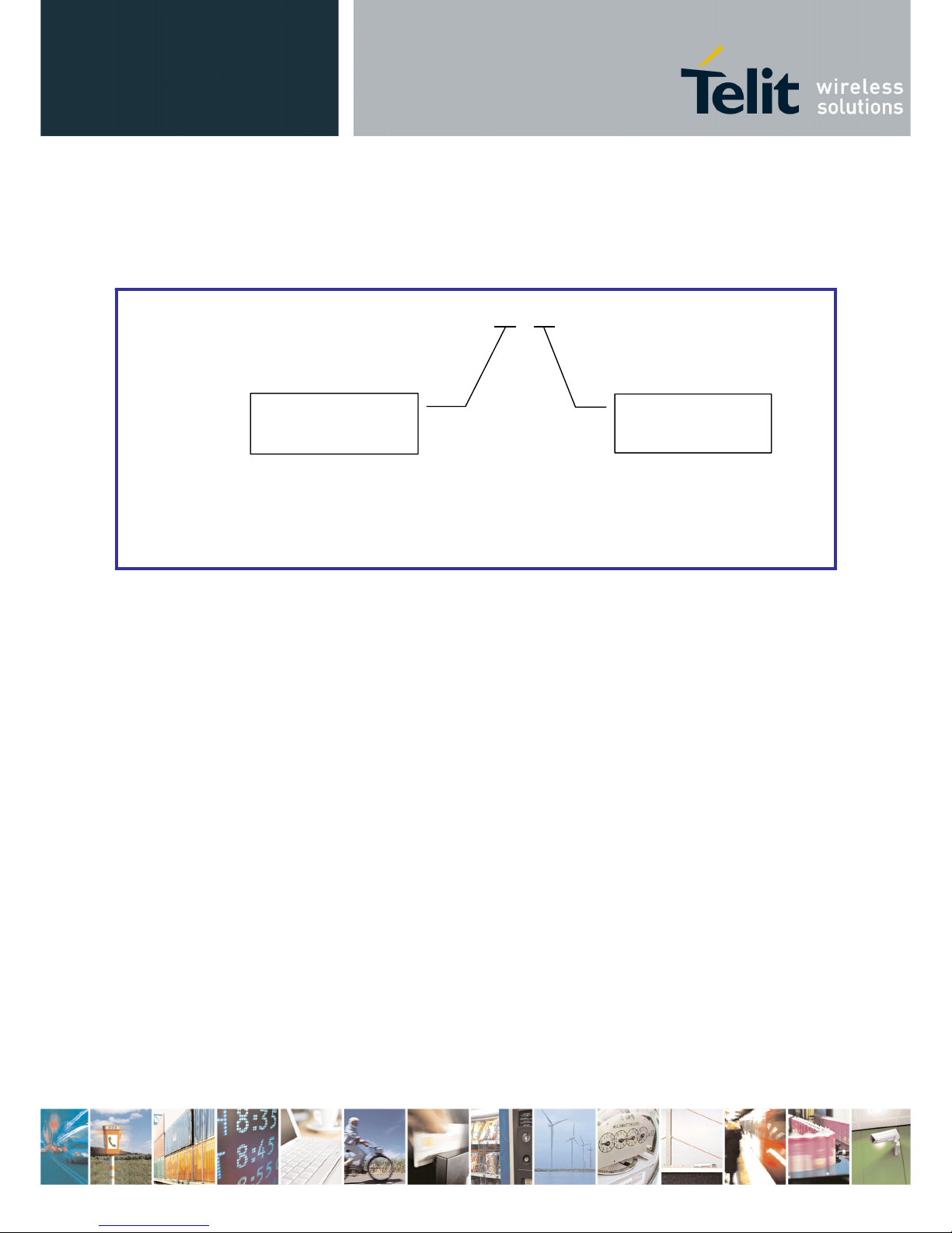
IV.7. Configuration and Download Over The Air (DOTA)
TinyPlus terminal includes the new DOTA functionality. This function is able to change or update the firmware of a
remote terminal, using a local terminal. In this application, the new firmware is sent through the radio link to another
device without the need of any hardware intervention on the remote device. All steps of the process can be done
from a local radio terminal connected to a computer.
Firmware or settings
are sent through the air
without any access to
the remote device
Hardly accessible remote
terminal to be updated or
configured
Local terminal
Completing DOTA, the configuration over the air functionality gives access to the Hayes mode of a remote terminal.
Thanks to it, you can adjust all the settings of a terminal without physical access to it.
Both functionalities are available through a specific software tool “TinyTools”. Refer to its user manual ([4]) for
detailed explanation.
Page 41

TinyOne Plus 868MHz Terminal User Guide
Reproduction forbidden without Telit Communications S.p.A. written authorization - All Rights Reserved page 41 of 47
1vv0300826 Rev.3 – 14/01/2011
CHAPTER V. ANNEXES
V.1. Modems’ Installation: Principles and cautions
¾ You must use the power supply and serial cable provided by Telit with the modem. Take care of
the polarity for the power supply connection (red wire +Vcc, black wire GND).
¾ The ON/OFF switching capability of the power supply is external to the modem.
¾ The radio environment should be closely studied prior to any installation with a spectrum analyzer
in order to determine whether and where the installation will be optimal.
¾ In case of outdoor installations, IP casings are recommended.
¾ In case of a ceiling installation, the modem should be mounted upside down for a better radiation
¾ A 1 m distance between two modems should be respected under 25 mW power output, at least 2
m at 100 mW and 3 m at 500 mW.
¾ The modems should be located as high and as free as possible so that a line of sight propagation
is established between modems.
¾ The modem should not be surrounded by metallic masses because of the disturbances caused
by a reflection phenomena.
¾ The electrical disturbances can come from various sources and should be avoided
o Engines
o High current devices
o Power relays, transformers
o Etc...
¾ The radio disturbances should also be avoided:
o System in the same frequency band such as cars remote control systems.
o Systems in a nearby frequency band such as high power (2 W) talkie-walkie systems.
¾ Vibrations and/or shocks can also be source of disturbances. It is therefore advised to mount the
modems in silent-blocks in order to stabilize it whenever necessary.
¾ Distances, obstacles and weather conditions can strongly affect radio communications and cause
disturbances as well as communication breakdowns.
Page 42

TinyOne Plus 868MHz Terminal User Guide
Reproduction forbidden without Telit Communications S.p.A. written authorization - All Rights Reserved page 42 of 47
1vv0300826 Rev.3 – 14/01/2011
V.2. Connection to a RS422 or RS485 interface
M868-TinyPlus terminal is configured in RS232 mode by default : it allows to directly connect it on a PC
serial port.
To configure the terminal in RS422 or RS485 mode :
ª Go to Hayes Mode and configure S215 Register : set to '2' for RS485 and to '1' for RS422.
ª Power Off the terminal.
ª Connect RS485 or RS422 serial link to the terminal.
ª Connect RS232/422 pin to GND or set RS232/485 switch to RS485 side.
ª Power On the terminal.
NOTE: if you Power off Board and set RS232/422 pin open, RS485/RS422 is inactivate and RS232 is activate.
Page 43

TinyOne Plus 868MHz Terminal User Guide
Reproduction forbidden without Telit Communications S.p.A. written authorization - All Rights Reserved page 43 of 47
1vv0300826 Rev.3 – 14/01/2011
V.3. ETSI 300 220-3 Version 1.3.1 standards (summary)
Page 44

TinyOne Plus 868MHz Terminal User Guide
Reproduction forbidden without Telit Communications S.p.A. written authorization - All Rights Reserved page 44 of 47
1vv0300826 Rev.3 – 14/01/2011
Page 45

TinyOne Plus 868MHz Terminal User Guide
Reproduction forbidden without Telit Communications S.p.A. written authorization - All Rights Reserved page 45 of 47
1vv0300826 Rev.3 – 14/01/2011
Page 46

TinyOne Plus 868MHz Terminal User Guide
Reproduction forbidden without Telit Communications S.p.A. written authorization - All Rights Reserved page 46 of 47
1vv0300826 Rev.3 – 14/01/2011
V.4. Examples of propagation attenuation
433 MHz 868 MHz 2.4 GHz
Factor
Loss Attenuation Loss Attenuation Loss Attenuation
Open office 0 % 0 dB 0 % 0 dB 0 % 0 dB
Window < 5 % < 1 dB 15 % 1 – 2 dB 30 % 3 dB
Thin wall (plaster) 25 % 3 dB 35 % 3 – 4 dB 50 % 5 – 8 dB
Medium wall (wood) 40 % 4 – 6 dB 50 % 5 – 8 dB 70 % 10 – 12 dB
Thick wall (concrete) 50 % 5 – 8 dB 60 % 9 – 11 dB 85 % 15 – 20 dB
Armoured wall (reinforced concrete) 70 % 10 – 12 dB 80 % 12 – 15 dB 90 % 20 – 25 dB
Floor or ceiling 50 % 5 – 8 dB 60 % 9 – 11 dB 85 % 15 – 20 dB
Armoured floor or ceiling 70 % 10 – 12 dB 80 % 12 – 15 dB 90 % 20 – 25 dB
Rain and/or Fog 90 % 20 – 25 dB 95 % 25 – 30 dB ?? * ?? *
* = Attenuations increase along with the frequency. In some cases, it
is therefore difficult to determine loss and attenuation value.
Note = The table above is only indicative. The real values will depend on
the installation environment itself.
Page 47

TinyOne Plus 868MHz Terminal User Guide
Reproduction forbidden without Telit Communications S.p.A. written authorization - All Rights Reserved page 47 of 47
1vv0300826 Rev.3 – 14/01/2011
V.5. Declarations of Compliance
 Loading...