

Page 1

GS2200M
IP2WiFi Adapter Command
Reference Guide
1VV0301501 Rev. 1.0 – 2018-03-12
Page 2

SPECIFICATIONS ARE SUBJECT TO CHANGE WITHOUT NOTICE
NOTICE
While reasonable efforts have been made to assure the accuracy of this document, Telit
assumes no liability resulting from any inaccuracies or omissions in this document, or from
use of the information obtained herein. The information in this document has been carefully
checked and is believed to be reliable. However, no responsibility is assumed for
inaccuracies or omissions. Telit reserves the right to make changes to any products described
herein and reserves the right to revise this document and to make changes from time to time
in content hereof with no obligation to notify any person of revisions or changes. Telit does not
assume any liability arising out of the application or use of any product, software, or circuit
described herein; neither does it convey license under its patent rights or the rights of others.
It is possible that this publication may contain references to, or information about Telit
products (machines and programs), programming, or services that are not announced in your
country. Such references or information must not be construed to mean that Telit intends to
announce such Telit products, programming, or services in your country.
COPYRIGHTS
This instruction manual and the Telit products described in this instruction manual may be,
include or describe copyrighted Telit material, such as computer programs stored in
semiconductor memories or other media. Laws in the Italy and other countries preserve for
Telit and its licensors certain exclusive rights for copyrighted material, including the exclusive
right to copy, reproduce in any form, distribute and make derivative works of the copyrighted
material. Accordingly, any copyrighted material of Telit and its licensor contained herein or in
the Telit products described in this instruction manual may not be copied, reproduced,
distributed, merged or modified in any manner without the express written permission of Telit.
Furthermore, the purchase of Telit products shall not be deemed to grant either directly or by
implication, estoppel, or otherwise, any license under the copyrights, patents or patent
applications of Telit, as arises by operation of law in the sale of a product.
COMPUTER SOFTWARE COPYRIGHTS
The Telit and 3rd Party supplied Software (SW) products described in this instruction manual
may include copyrighted Telit and other 3rd Party supplied computer programs stored in
semiconductor memories or other media. Laws in the Italy and other countries preserve for
Telit and other 3rd Party supplied SW certain exclusive rights for copyrighted computer programs, including the exclusive right to copy or reproduce in any form the copyrighted computer program. Accordingly, any copyrighted Telit or other 3rd Party supplied SW computer
programs contained in the Telit products described in this instruction manual may not be copied (reverse engineered) or reproduced in any manner without the express written permission
of Telit or the 3rd Party SW supplier. Furthermore, the purchase of Telit products shall not be
deemed to grant either directly or by implication, estoppel, or otherwise, any license under the
copyrights, patents or patent applications of Telit or other 3rd Party supplied SW, except for
the normal non-exclusive, royalty free license to use that arises by operation of law in the sale
of a product.
Page 3

USAGE AND DISCLOSURE RESTRICTIONS
I. License Agreements
The software described in this document is the property of Telit and its licensors. It is
furnished by express license agreement only and may be used only in accordance with the
terms of such an agreement.
II. Copyrighted Materials
Software and documentation are copyrighted materials. Making unauthorized copies is
prohibited by law. No part of the software or documentation may be reproduced, transmitted,
transcribed, stored in a retrieval system, or translated into any language or computer
language, in any form or by any means, without prior written permission of Telit
III. High Risk Materials
Components, units, or third-party products used in the product described herein are NOT
fault-tolerant and are NOT designed, manufactured, or intended for use as on-line control
equipment in the following hazardous environments requiring fail-safe controls: the operation
of Nuclear Facilities, Aircraft Navigation or Aircraft Communication Systems, Air Traffic
Control, Life Support, or Weapons Systems (High Risk Activities”). Telit and its supplier(s)
specifically disclaim any expressed or implied warranty of fitness for such High Risk Activities.
IV. Trademarks
TELIT and the Stylized T Logo are registered in Trademark Office. All other product or service
names are the property of their respective owners.
V. Third Party Rights
The software may include Third Party Right software. In this case you agree to comply with all
terms and conditions imposed on you in respect of such separate software. In addition to
Third Party Terms, the disclaimer of warranty and limitation of liability provisions in this
License shall apply to the Third Party Right software.
TELIT HEREBY DISCLAIMS ANY AND ALL WARRANTIES EXPRESS OR IMPLIED FROM
ANY THIRD PARTIES REGARDING ANY SEPARATE FILES, ANY THIRD PARTY
MATERIALS INCLUDED IN THE SOFTWARE, ANY THIRD PARTY MATERIALS FROM
WHICH THE SOFTWARE IS DERIVED (COLLECTIVELY “OTHER CODE”), AND THE USE
OF ANY OR ALL THE OTHER CODE IN CONNECTION WITH THE SOFTWARE,
INCLUDING (WITHOUT LIMITATION) ANY WARRANTIES OF SATISFACTORY QUALITY
OR FITNESS FOR A PARTICULAR PURPOSE.
NO THIRD PARTY LICENSORS OF OTHER CODE SHALL HAVE ANY LIABILITY FOR ANY
DIRECT, INDIRECT, INCIDENTAL, SPECIAL, EXEMPLARY, OR CONSEQUENTIAL
DAMAGES (INCLUDING WITHOUT LIMITATION LOST PROFITS), HOWEVER CAUSED
AND WHETHER MADE UNDER CONTRACT, TORT OR OTHER LEGAL THEORY,
ARISING IN ANY WAY OUT OF THE USE OR DISTRIBUTION OF THE OTHER CODE OR
THE EXERCISE OF ANY RIGHTS GRANTED UNDER EITHER OR BOTH THIS LICENSE
AND THE LEGAL TERMS APPLICABLE TO ANY SEPARATE FILES, EVEN IF ADVISED
OF THE POSSIBILITY OF SUCH DAMAGES.
Page 4

APPLICABILITY TABLE
PRODUCT
GS2200M
Software Release
5.5.2
Page 5

GS2200M IP2WiFi Adapter Command Reference Guide
Table of Contents
Chapter 1 Getting Started ................................................................................................................ 19
1.1 Overview ................................................................................................................................19
1.2 Using SDK Builder .................................................................................................................21
1.2.1 IP-to-WiFi Module Information .....................................................................................21
Chapter 2 Architecture ..................................................................................................................... 23
2.1 Overview ................................................................................................................................23
2.2 Serial Interface ......................................................................................................................24
2.3 System Initialization ...............................................................................................................24
2.3.1 Profile Definition ...........................................................................................................25
2.4 Command Processing Mode .................................................................................................26
2.5 Data Handling ........................................................................................................................27
2.5.1 Unsolicited/Unassociated/Beacon Mode Data Handling ..............................................28
2.5.2 Software Flow Control ..................................................................................................28
2.5.3 Hardware Flow Control ................................................................................................28
2.6 Serial Data Handling ..............................................................................................................29
2.7 Wireless Network Management ............................................................................................. 30
2.7.1 Scanning ......................................................................................................................30
2.7.2 Association ...................................................................................................................30
2.7.3 SSID and Passphrase ..................................................................................................30
Chapter 3 Host Interaction ............................................................................................................... 33
3.1 Startup Handling ....................................................................................................................34
3.1.1 Single Interface Startup Handling ................................................................................34
3.1.2 Dual Interface Startup Handling ................................................................................... 35
3.2 Interface .................................................................................................................................35
3.2.1 UART ...........................................................................................................................35
3.2.1.1 UART Parameters ...............................................................................................35
3.2.1.2 Software Flow Control .........................................................................................37
3.2.1.3 Hardware Flow Control ........................................................................................38
3.2.2 SPI Interface and Configuration ................................................................................... 39
3.2.2.1 SPI Byte Stuffing (Legacy SPI, SPI-NO-DMA) ....................................................40
3.2.2.2 SPI Command Response (SPI-DMA) .................................................................. 41
3.2.2.3 Annexure - HI Frame Format (From Host) ...........................................................52
3.2.2.4 Annexure - HI Frame Response (From GS Node) ..............................................53
3.2.2.5 Pin Connection for SPI Interface .........................................................................54
3.2.3 SDIO Interface .............................................................................................................55
3.2.3.1 Capabilities ..........................................................................................................55
3.2.3.2 SDIO Host Slave Initialization and Communication ............................................. 56
3.2.3.3 SDIO Host Recommendations .............................................................................59
3.2.3.4 Pin Description .....................................................................................................61
3.2.4 Interface Verification ....................................................................................................61
Chapter 4 General Operations ......................................................................................................... 63
4.1 Version ..................................................................................................................................63
4.2 Time Setting ..........................................................................................................................65
4.2.1 Set System Time ..........................................................................................................65
4.2.1.1 Manual Setting ..................................................................................................... 65
4.2.2 Get System Time .........................................................................................................66
1VV030 1501 Rev. 1.0 5 2018-03-12
Page 6

GS2200M IP2WiFi Adapter Command Reference Guide
4.3 Profile Setting ........................................................................................................................67
4.3.1 Get Profile ....................................................................................................................67
4.3.2 Save Profile ..................................................................................................................68
4.3.3 Load Profile ..................................................................................................................69
4.3.4 Select Default Profile ....................................................................................................70
4.3.5 Restore Profile .............................................................................................................71
4.3.6 Define Profile ................................................................................................................71
4.3.7 Identification Information ..............................................................................................73
4.3.8 Enhanced Asynchronous Notification ..........................................................................74
4.4 Reset .....................................................................................................................................75
4.5 MAC .......................................................................................................................................76
4.5.1 Set MAC Address .........................................................................................................76
4.5.2 Get MAC Address ........................................................................................................78
Chapter 5 Wireless ......................................................................................................................... 81
5.1 Wireless Generic ...................................................................................................................81
5.1.1 Regulatory Domain ......................................................................................................81
5.1.1.1 Set Regulatory Domain ........................................................................................81
5.1.1.2 Get Regulatory Domain .......................................................................................82
5.1.2 Operation Mode ...........................................................................................................83
5.1.3 MAC Retry ...................................................................................................................86
5.1.4 Sync Loss Interval ........................................................................................................87
5.1.5 Set RTS Threshold .......................................................................................................88
5.1.6 Transmit Data Rate ......................................................................................................89
5.1.6.1 Set Transmit Rate ................................................................................................ 89
5.1.6.2 Get Transmit Rate ...............................................................................................91
5.1.7 Graceful Shutdown of WLAN .......................................................................................92
5.2 Beacon Mode (Unassociated Mode) .....................................................................................93
5.2.1 Unassociated/Unsolicited Tx ........................................................................................93
5.2.2 Unassociated/Unsolicited Rx .......................................................................................98
5.2.2.1 Examples for Unassociated/Unsolicited Tx and Rx Commands ........................101
5.2.3 Unassociated/Unsolicited Rx Stop ............................................................................. 102
5.2.4 Unassociated/Unsolicited Data Encryption ................................................................103
5.3 Station/AP Mode ..................................................................................................................104
5.3.1 Scan Time Settings ....................................................................................................104
5.3.1.1 Set Scan Time ...................................................................................................104
5.3.1.2 Get Scan Time ................................................................................................... 105
5.3.2 Authentication Mode ..................................................................................................106
5.3.3 Security Configuration ................................................................................................107
5.3.3.1 Security Setting ..................................................................................................107
5.3.3.2 WEP Keys ..........................................................................................................108
5.3.3.3 WEP Key Type Configuration ............................................................................109
5.3.3.4 WPA-PSK and WPA2-PSK Passphrase ............................................................111
5.3.3.5 WPA-PSK and WPA2-PSK Key Calculation ......................................................112
5.3.3.6 WPA-PSK and WPA2-PSK Key ........................................................................113
5.3.4 Scanning ....................................................................................................................115
5.3.5 Association .................................................................................................................117
5.3.6 Disassociation ............................................................................................................120
5.3.7 Connection Maintenance ...........................................................................................120
5.3.7.1 Keep Alive Timer ...............................................................................................120
5.3.7.2 WLAN Keep Alive Interval .................................................................................121
5.3.8 Advanced Commands ................................................................................................122
5.3.8.1 Get Client Information ........................................................................................ 122
5.4 WiFi Direct Mode .................................................................................................................123
1VV030 1501 Rev. 1.0 6 2018-03-12
Page 7

GS2200M IP2WiFi Adapter Command Reference Guide
5.4.1 Set Device ..................................................................................................................123
5.4.2 Set WPS .....................................................................................................................125
5.4.3 Start Find ....................................................................................................................126
5.4.4 Stop Find ....................................................................................................................129
5.4.5 Provoke ......................................................................................................................130
5.4.6 Provision Discovery ....................................................................................................131
5.4.7 Group Form (Group Owner Negotiation) ....................................................................132
5.4.7.1 Provision Discovery Request Handling ..............................................................136
5.4.8 Client Join ..................................................................................................................138
5.4.9 Invitation Procedures .................................................................................................140
5.4.10 Disconnect ...............................................................................................................141
Chapter 6 Power Management - Radio and System ..................................................................... 143
6.1 Radio Receiver Setting ........................................................................................................143
6.1.1 Active Radio Receive ................................................................................................. 143
6.1.2 Standard Power Save Radio Receive based on DTIM/Listen Interval .......................145
6.1.2.1 IEEE PS Poll Listen Interval ..............................................................................145
6.1.3 Custom Power Save Radio Receive .......................................................................... 148
6.2 Battery Measurement ..........................................................................................................149
6.2.1 Battery Check Start ....................................................................................................149
6.2.2 Battery Warning/Standby Level Set ...........................................................................150
6.2.3 Battery Check Set ......................................................................................................151
6.2.4 Battery Check Stop ....................................................................................................152
6.2.5 Battery Value Get .......................................................................................................152
6.3 System Power Save ............................................................................................................153
6.3.1 Hibernate ....................................................................................................................153
6.3.2 Standby ......................................................................................................................154
6.3.2.1 Putting the System in Standby ...........................................................................154
6.3.2.2 Enabling Standby Mode Between Beacons .......................................................156
6.3.2.3 Configuring Standby Between Beacons ............................................................157
6.3.3 Deep Sleep ................................................................................................................160
6.3.4 Power Save in Limited AP ..........................................................................................162
6.3.5 Hardware Cryptography ............................................................................................. 163
Chapter 7 Peripherals .................................................................................................................... 165
7.1 GPIO Commands ................................................................................................................165
7.1.1 GPIO Out HIGH/LOW ................................................................................................165
Chapter 8 Production and Debug .................................................................................................. 167
8.1 RF Test ................................................................................................................................167
8.1.1 Regulatory and Transmit Tests using RF Test Commands .......................................167
8.1.1.1 Regulatory Testing .............................................................................................167
8.1.1.2 Transmit Testing ................................................................................................167
8.1.1.3 Gain Control Table .............................................................................................168
8.1.1.4 Start RF Test .....................................................................................................168
8.1.1.5 Stop RF Test ......................................................................................................168
8.1.1.6 Asynchronous Frame Transmission ..................................................................168
8.1.1.7 Start Asynchronous Frame Reception ............................................................... 170
8.1.1.8 Stop Asynchronous Frame Reception ...............................................................173
8.1.1.9 Asynchronous Frame Transmission (TX99 mode) ............................................174
8.1.1.10 Asynchronous Frame Transmission (TX100 mode) ........................................179
8.1.1.11 Carrier Wave Transmission .............................................................................181
8.2 Live Calibration ....................................................................................................................182
8.2.1 Enable Live Calibration ..............................................................................................182
1VV030 1501 Rev. 1.0 7 2018-03-12
Page 8

GS2200M IP2WiFi Adapter Command Reference Guide
8.2.2 Erase Live Calibration ................................................................................................184
8.2.3 Start Live Calibration ..................................................................................................185
8.2.4 For Complete Sequence of Live Calibration ..............................................................187
8.3 Debug .................................................................................................................................. 187
8.3.1 Log Level ....................................................................................................................187
8.3.2 Echo ...........................................................................................................................188
8.3.3 Verbose ......................................................................................................................189
8.3.4 RSSI ...........................................................................................................................190
8.3.5 WLAN Status ..............................................................................................................190
8.3.6 WLAN Statistics .........................................................................................................191
Appendix A Response Codes ........................................................................................................ 195
A.1 Synchronous Messages ......................................................................................................195
A.2 Asynchronous & Enhanced Asynchronous Messages ........................................................ 195
A.3.1 Exception Messages ..................................................................................................199
A.3.2 Boot Messages ..........................................................................................................200
1VV030 1501 Rev. 1.0 8 2018-03-12
Page 9

GS2200M IP2WiFi Adapter Command Reference Guide
About This Manual
This manual provides guidelines for using the GainSpan® AT command-line interface to
design, configure, and provision the GS2200M series module to enable IP-to-WiFi
embedded devices with a UART/SPI interface to access an 802.11-compliant WiFi wireless
network connection using only serial commands.
Refer to the following sections:
• Revision History, page 9
• Audience, page 9
• Standards, page 10
• Documentation Conventions, page 10
• Documentation, page 13
• References, page 13
• Contact Information, Support, page 15
• Returning Products to GainSpan, page 16
• Accessing the GainSpan Portal, page 16
Revision History
This revision history of the GainSpan IP-to-WiFi Adapter Application Programmer
Reference Guide is maintained in the following table:
Table 1 Revision History
Version Date Remarks
1.0 March2018 Initial Release
Audience
This manual is designed for software engineers who want to evaluate, design, and
implement GainSpan Ultra Low Power 802.11 WiFi Modules within their environment. To
use this manual you will need a basic understanding of WiFi networks, network principles,
and network protocols.
1VV0301501 Rev. 1.0 9 2018-03-12
Page 10

GS2200M IP2WiFi Adapter Command Reference Guide
Standards
The standards that are supported by the GainSpan GS module series are:
– IEEE 802.11 b/g/n
Documentation Conventions
This manual uses the following text and syntax conventions:
– Special text fonts represent particular commands, keywords, variables, or window
sessions
– Color text indicates cross-reference hyper links to supplemental information
– Command notation indicates commands, subcommands, or command elements
Table 2, page 10, describes the text conventions used in this manual for software
procedures that are explained using the AT command line interface.
Table 2 Document Text Conventions
Convention Type Description
This monospaced font represents command strings entered on a
command syntax
command line and sample source code.
monospaced font
AT XXXX
Proportional font
description
UPPERCASE
Gives specific details about a parameter.
<Data> DATA
Indicates user input. Enter a value according to the descriptions that
follow. Each uppercased token expands into one or more other token.
Variable parameter
lowercase
Indicates keywords. Enter values exactly as shown in the command
description.
Keyword parameter
Enclose optional parameters. Choose none; or select one or more an
[ ]
Square brackets
unlimited number of times each. Do not enter brackets as part of any
command.
[parm1|parm2|parm3]
?
Question mark
Used with the square brackets to limit the immediately following token
to one occurrence.
Each escape sequence <ESC> starts with the ASCII character 27 (0x1B).
<ESC>
This is equivalent to the Escape key.
Escape sequence
<ESC>C
1VV0301501 Rev. 1.0 10 2018-03-12
Page 11

GS2200M IP2WiFi Adapter Command Reference Guide
Table 2 Document Text Conventions (Continued)
Convention Type Description
<CR>
Carriage return
<LF>
Line feed
<CR> <LF>
Carriage return
Line feed
< >
Angle brackets
=
Equal sign
.
dot (period)
A.B.C.D
IP address
Each command is terminated by a carriage return.
Each command is terminated by a line feed.
Each response is started with a carriage return and line feed with some
exceptions.
Enclose a numeric range, endpoints inclusive. Do not enter angle
brackets as part of any command.
<SSID>
Separates the variable from explanatory text. Is entered as part of the
command.
PROCESSID = <CID>
Allows the repetition of the element that immediately follows it multiple
times. Do not enter as part of the command.
.AA:NN can be expanded to 1:01 1:02 1:03.
IPv4-style address.
10.0.11.123
LINE
End-to-line input token
WORD
Single token
Indicates user input of any string, including spaces. No other parameters
may be entered after input for this token.
string of words
Indicates user input of any contiguous string (excluding spaces).
singlewordnospaces
1VV0301501 Rev. 1.0 11 2018-03-12
Page 12

GS2200M IP2WiFi Adapter Command Reference Guide
Table 3, page 12, describes the symbol conventions used in this manual for notification and
important instructions.
Table 3 Symbol Conventions
Icon Type Description
Provides helpful suggestions needed in understanding
Note
a feature or references to material not available in the
manual.
Alert
Caution
Warning
Electro-Static Discharge
(ESD)
Alerts you of potential damage to a program, device,
or system or the loss of data or service.
Cautions you about a situation that could result in
minor or moderate bodily injury if not avoided.
Warns you of a potential situation that could result in
death or serious bodily injury if not avoided.
Notifies you to take proper grounding precautions
before handling a product.
1VV0301501 Rev. 1.0 12 2018-03-12
Page 13

GS2200M IP2WiFi Adapter Command Reference Guide
Documentation
Part Number Document Title Description
1VV0301396
1VV0301444
The GainSpan documentation suite listed in Table 4, page 13 includes the part number,
documentation name, and a description of the document. The documents are available from
the GainSpan Portal. Refer to Accessing the GainSpan Portal, page 16 for details.
Table 4 Documentation List
Provides information to help WiFi
GS2200M Low Power WiFi Mini-Module Hardware User
Guide
GS2K S2W Use Case Reference Guide
system designers to build systems using
GainSpan GS2200M module and
develop wireless applications.
Provides references for using GainSpan
AT commands and its usage in different
scenarios using different features and
protocols.
Documentation Feedback
We encourage you to provide feedback, comments, and suggestions so that we can improve
the documentation. You can send your comments by logging into Telit Support Portal. If
you are using e-mail, be sure to include the following information with your comments:
– Document name
– URL or page number
– Hardware release version (if applicable)
– Software release version (if applicable)
References
The GainSpan references listed in Table 5, page 14 are available on the GainSpan Portal.
Refer to Accessing the GainSpan Portal, page 16 for details.
1VV0301501 Rev. 1.0 13 2018-03-12
Page 14

GS2200M IP2WiFi Adapter Command Reference Guide
Table 5 Other Documents and References
Title Description
Schematics
Module Firmware and
Programming Utilities
Software Utilities
GS Based Module Evaluation Board schematics
supporting:
GS2200M
• IP-to-WiFi (IP2WiFi) based firmware
• Firmware Release Notes
• GSFlashprogram utility for programming the
modules
Serial terminal program to evaluate and demonstrate
IP-to-WiFi (IP2WiFi) applications such as
– gs2k_flashprogram.exe
1VV0301501 Rev. 1.0 14 2018-03-12
Page 15

GS2200M IP2WiFi Adapter Command Reference Guide
Contact Information, Support
For general contact, technical support services, technical questions and to report
documentation errors contact Telit Technical Support at:
TS-SRD@telit.com
We recommend adding “Wi-Fi” in subject of the email. For example, the subject of email
can be “Wi-Fi: Your actual issue or question in brief” like “Wi-Fi: SPI Driver Issue”.
Also, in description of your email, please provide details about the issue, product and
module including software firmware version, module version and type, application being
used, customizations done to application, use case, issue frequency, and ability to recreate
it among other things wherever applicable.
Alternatively, for more Technical Support information or assistance, perform the following
steps:
1. Visit http://www.telit.com, go to Products> Wi-Fi and Blue-tooth, then scroll down to
the Telit Wi- Fi Portal.
2. Click Access the Portal Here icon which will direct you to the GainSpan portal
http://www.gainspan/secure/login.com
1. Log in with your customer Email and Password.
2. Select the Location.
3. Select Q&A tab.
4. Select Ask a New Question.
5. Enter your technical support question, product information, and a brief description.
For detailed information about where you can buy the Telit modules or for
recommendations on accessories and components visit:
http://www.telit.com
Our aim is to make this guide as helpful as possible. Keep us informed of your comments
and suggestions for improvements. Telit appreciates feedback from the users of our
information.
1VV0301501 Rev. 1.0 15 2018-03-12
Page 16

GS2200M IP2WiFi Adapter Command Reference Guide
Returning Products to GainSpan
If a problem cannot be resolved by GainSpan technical support, a Return Material
Authorization (RMA) is issued. This number is used to track the returned material at the
factory and to return repaired or new components to the customer as needed.
NOTE: Do not return any components to GainSpan Corporation unless you have
first obtained an RMA number. GainSpan reserves the right to refuse shipments
that do not have an RMA. Refused shipments will be returned to the customer by
collect freight.
To return a hardware component:
1. Determine the part number and serial number of the component.
2. Obtain an RMA number from Sales/Distributor Representative.
3. Provide the following information in an e-mail or during the telephone call:
– Part number and serial number of component
– Your name, organization name, telephone number, and fax number
– Description of the failure
4. The support representative validates your request and issues an RMA number for
return of the components.
5. Pack the component for shipment.
Guidelines for Packing Components for Shipment
To pack and ship individual components:
– When you return components, make sure they are adequately protected with
packing materials and packed so that the pieces are prevented from moving
around inside the carton.
– Use the original shipping materials if they are available.
– Place individual components in electrostatic bags.
– Write the RMA number on the exterior of the box to ensure proper tracking.
CAUTION! Do not stack any of the components.
Accessing the GainSpan Portal
To find the latest version of GainSpan documentation supporting the GainSpan product
release you are interested in, you can search the GainSpan Portal website by performing the
following steps:
1VV0301501 Rev. 1.0 16 2018-03-12
Page 17

GS2200M IP2WiFi Adapter Command Reference Guide
NOTE: You must first contact GainSpan to set up an account, and obtain a
customer user name and password before you can access the GainSpan Portal.
1. Visit http://www.telit.com, go to Products> Wi-Fi and Blue-tooth, then scroll down
the Telit Wi- Fi Portal.
2. Click Access the Portal Here icon which will direct you to the GainSpan portal
http://www.gainspan/secure/login.com
3. Log in using your customer Email and Password.
4. Click the Getting Started tab to view a Quick Start tutorial on how to use various
features within the GainSpan Portal.
5. Click the Agreements tab to download and upload the SLA for ADK and SDK
respectively.
6. Click on the Documents tab to search, download, and print GainSpan product
documentation.
7. Click the Software tab to search and download the latest software versions.
8. Click the Kits Purchased tab to view customer account history.
9. Click the Legal Documents tab to view GainSpan Non-Disclosure Agreement
(NDA).
10. Click the Certifications tab to view GainSpan certifications.
1VV0301501 Rev. 1.0 17 2018-03-12
Page 18

GS2200M IP2WiFi Adapter Command Reference Guide
1VV0301501 Rev. 1.0 18 2018-03-12
Page 19

GS2200M IP2WiFi Adapter Command Reference Guide
Chapter 1 Getting Started
This chapter describes how to get started.
• Overview, page 19
• Using SDK Builder, page 21
1.1 Overview
The IP-to-WiFi stack is used to provide WiFi capability to any device having a serial
interface. This approach offloads WLAN, TCP/IP stack and network management
overhead to the WiFi chip, allowing a small embedded host (for example an MCU) to
communicate with other hosts on the network using a WiFi wireless link. The host
processor can use serial commands to configure the IP-to-WiFi Application and to create
wireless and network connections.
OTP stands for One Time Programmable Memory. It is divided into two parts, one for
Application firmware and another for WLAN firmware. It contains important system
related information for Application and WLAN firmware. For Application firmware, it
contains information about MAC address, regularity information, module related
information, and so on. For WLAN firmware, it contains information about calibration
data.
The user will have to register on GainSpan website, sign the NDA and check with the local
sales team for any queries during this procedure. This gives access to all the respective
documentation according to the product purchased.
The following is the basic application development sequence for a IP-to-WiFi user.
1. Evaluate GainSpan hardware and firmware
– Download the software, program, and execute.
– To download the software, go to SDK builder (www.gainspan.com/secure/login),
and download all the latest packages including the binary (Refer GS2K SDK
Builder User Guide).
– Flash the binary using module programmer user guide on the custom hardware or
GS evaluation board and execute in RUN mode. (Refer “GS2K Module
Programming User Guide”).
2. Design the custom hardware by following the design guidelines. (Refer GS2xxxM
Hardware Design Guidelines)
1VV0301501 Rev. 1.0 19 2018-03-12
Page 20

GS2200M IP2WiFi Adapter Command Reference Guide
3. Develop Host firmware
– Following Live Calibrations commands are highly recommended to be issued
before doing any Wi-Fi operations:
AT+WLCALERASE
AT+RESET
AT+WLCALSTART=1
– Interface host application using AT commands. (Refer GS2xxxM S2W Adapter
Command Reference Guide)
Configure the serial interface (UART/SPI/SDIO) as required, refer UART,
page 35, SPI Interface and Configuration, page 39 and SDIO Interface, page 55 for
mode, polarity.For software interface, choose Command & Response, Byte
stuffing/de-stuffing as “None” for UART and SDIO options.
NOTE: For desired functionality use appropriate AT Commands. Refer “GS2K
S2W Reference Use Case User Guide”
– Issue general, power save, and security related commands as required.
– Start connection to an Access Point or do provisioning as required.
– Obtain IP Address and Start Data Transfer.
– Select advanced services if any.
4. Debug Host and GainSpan module
– Debug using provided AT commands and other options if required. (Refer
GS2xxxM S2W Adapter Command Reference Guide)
– Analyze using Wire shark over wireless. For more details, refer information about
AirPcap Nx in http://www.riverbed.com
5. Production Process
– Perform generic recommendations in production line
– Check if Live Calibration needs to be explicitly controlled (rarely used),
– Perform RF tests
NOTE: Refer to “GS2K S2W Reference Use Case User Guide” document for
detailed use cases and examples.
1VV0301501 Rev. 1.0 20 2018-03-12
Page 21

GS2200M IP2WiFi Adapter Command Reference Guide
1.2 Using SDK Builder
1.2.1 IP-to-WiFi Module Information
Selecting the IP-to-WiFi (Hosted) under the SDK Builder Configuration screen displays
the module information that includes the module selected, firmware version, application,
SRAM (APP/WLAN/RTC), and Flash (Internal/External) summary information. There
are several tabs that allow you to select various features and options to build and configure
the IP-to-WiFi (Hosted) application.
1VV0301501 Rev. 1.0 21 2018-03-12
Page 22
GS2200M IP2WiFi Adapter Command Reference Guide
NOTE: When building Firmware Binary for EVK or AEK Package, it is
recommended that you use the Default Evaluation Build. Otherwise, you can build
Custom, SDK, or ADK Packages for your environment.
The tabular selections to build your IP-to-WiFi (Hosted) application and firmware are as
follows
• Host Interface
• Host Settings
• 802.11 WLAN
• 802 WLRPAN
• ZigBee IP Modes
• Networking Services
• Energy Measurement
• Clock/Power Setting
• Memory Setting
Once you have completed selecting the options and features for building the IP-to-WiFi
(Hosted) firmware, click the Next button or select the Summary tab. The Build
Configuration Summary screen displays a summary of the selected configuration options
(e.g., Module Configuration, Host Interface, Host Settings, 802.11 WLAN, etc.).
1VV0301501 Rev. 1.0 22 2018-03-12
Page 23
GS2200M IP2WiFi Adapter Command Reference Guide
Chapter 2 Architecture
This chapter describes the overview and architecture of IP-to-WiFi Application.
• Overview, page 23
• Serial Interface, page 24
• System Initialization, page 24
• Command Processing Mode, page 26
• Data Handling, page 27
• Serial Data Handling, page 29
• Wireless Network Management, page 30
2.1 Overview
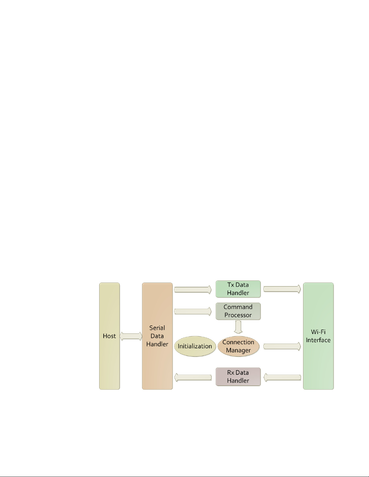
Figure 2, page 27 shows the overall architecture of the IP-to-WiFi (IP2WiFi) interface.
Transmit (Tx) and Receive (Rx) Data Handlers pass messages to and from the WiFi
interface. Commands related to management of the IP2WiFi interface and the network
connections are intercepted by a Command Processor. A Serial Data Handler translates data
to and from a serial interface (UART/SPI/SDIO).
Figure 1 Operation Modes of the IP-to-WiFi Application
The
IP-to-WiFi Application consists of the following modules:
• Serial Interface, page 24
1VV0301501 Rev. 1.0 23 2018-03-12
Page 24

GS2200M IP2WiFi Adapter Command Reference Guide
• System Initialization, page 24
• Command Processing Mode, page 26
• Data Handling, page 27
• Serial Data Handling, page 29
• Wireless Network Management, page 30
The software for the IP-to-WiFi Application is mainly driven using a state machine. Upon
powering on, the required initialization of all the modules is performed and then the state
machine is entered. This state machine is event-driven and processes the events received
from either the serial port or from the WiFi/Network interface as well as internal events
from its own modules. The state machine calls the appropriate handler for a given event per
the current state.
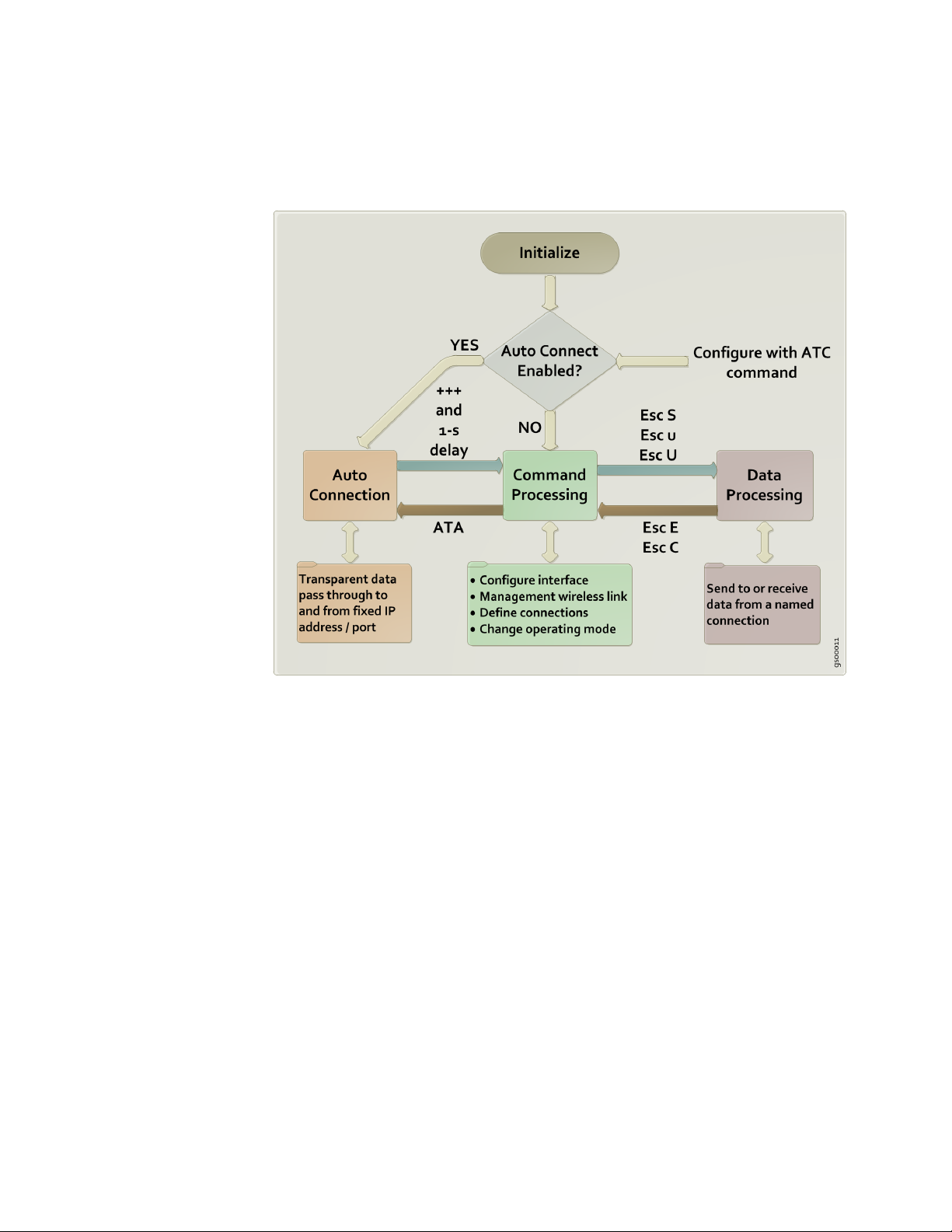
The IP-to-WiFi Application has three distinct operating modes (Figure 2, page 25). In the
default command processing operating mode, commands to configure and manage the
interface are sent over the serial interface. In the default mode, the node accepts commands
entered by the Host CPU and processes each of the commands. All commands are available
in this mode. The User can establish a data connection here and send data.
In data processing mode, data can be sent to, or received from the host.
For each mode, configuration parameters are stored in non-volatile memory. In addition to
factory-default parameter values, two user-defined profiles (0 and 1) are available. The
parameter set to be used is determined by a user command (see 4.3.4 Select Default Profile,
page 70).
2.2 Serial Interface
The serial interface used is determined by the interface configuration option selected when
building the binary using SDK Builder.
GS nodes do not support dynamic detection of serial interfaces as SPI or UART binaries
are built from the SDK builder.
2.3 System Initialization
Upon startup, the IP-to-WiFi (IP2WiFi) interface performs the following actions:
– During the initialization process, the module will search for a saved configuration
file. The configuration file include the auto connection settings, default profile
and profile settings. If a saved configuration file is available, it is loaded from
non-volatile memory. If no saved configuration file, the default settings will be
applied. If there are no saved parameters, the factory-default configuration is
loaded.
– The IP2WiFi application is initialized based on the profile settings.
1VV0301501 Rev. 1.0 24 2018-03-12
Page 25
GS2200M IP2WiFi Adapter Command Reference Guide
– Interface enters the command processing state.
Figure 2 Operating Modes of the IP-to-WiFi Application
IP-to-WiFi binary uses the interface and configuration as per the binary configuration
options selected in SDK Builder. The evaluation binary packages use the following
defaults:
• For UART: 115200 baud using 8 bit characters with no parity bits, one stop bit, and no
• For SPI: SPI Mode 0 (CPL=0, CPH=0)
Any changes to this configuration that were made in a previous session using the ATB
command (see 3.2.1.1 UART Parameters, page 35) will be lost when power is lost. To
make changes in the UART/SPI parameters that will persist across power cycling, the
relevant changes must be saved into the power-on profile using AT&W (see 4.3.2 Save
Profile, page 68) and AT&Y (see 4.3.4 Select Default Profile, page 70).
2.3.1 Profile Definition
The configuration parameter values that define the behavior of the GS node are grouped
into Profiles. These profiles are stored in non-volatile memory when not in use. The GS
node supports two Profiles by default.
flow control
1VV0301501 Rev. 1.0 25 2018-03-12
Page 26

GS2200M IP2WiFi Adapter Command Reference Guide
2.4 Command Processing Mode
In Command mode, the application receives commands over the serial port. Commands
are processed line by line.
Verbose Mode is used when referring to commands being executed, refers to the displaying
of status of any command executed in ASCII (human readable) format. When the Verbose
Mode is disabled, the output will simply be in numeric digits, each digit indicating a
particular status. Verbose Mode is enabled by default.
If echo is enabled then each character is echoed back on the serial port.
Each command is terminated with a carriage return <CR> or line feed <LF>.
Each response is started with a carriage return <CR> and line feed<LF>, with the
exception of the responses to the following commands:
The response to the following group of commands starts with a line feed <LF> only:
AT+WPAPSK=<SSID>,<Passphrase>
ATA
Unless otherwise specified, if Verbose Mode is enabled, then the response to a successful
command is the characters OK. The response to an unsuccessful command is the word
ERROR, followed by a detailed error message, if available. If verbose mode is disabled,
command responses is numerical with OK having a value of 0 and error codes represented
by positive integers.
1VV0301501 Rev. 1.0 26 2018-03-12
Page 27

GS2200M IP2WiFi Adapter Command Reference Guide
The default Time Out till S2W Application buffers the data from HOST is 100milliseconds
which can be configured using ATS Command, refer 4.3.7 Identification Information,
page 73.
2.5 Data Handling
In Data Processing Mode, data transfers are managed using various escape sequences.
Each escape sequence starts with the ASCII character 27 (0x1B); this is equivalent to the
ESC key. The encoding of data and related commands are described in the following pages.
This encoding is used for both transmitted and received data.
<ESC>R:<Length>:<Ethernet package>
Where the Ethernet Packet is:
<DstAddr><SrcAddr><EtherType><Payload>
The contents of < > are byte or byte stream.
Table 6, page 27 describes the Encoding of Data parameters.
Table 6 Encoding of Data Parameters
Parameter Description
Length The size of the Ethernet packet.
DstAddr The destination MAC address.
SrcAddr The source MAC address.
EtherType
Payload The raw data.
The type of the Ethernet packet. For example,
BACNET-over-Ethernet, EtherType is 0x0000.
1VV0301501 Rev. 1.0 27 2018-03-12
Page 28

GS2200M IP2WiFi Adapter Command Reference Guide
2.5.1 Unsolicited/Unassociated/Beacon Mode Data Handling
In Unsolicited Data Mode (data transmission without association), data transfer is
managed using escape sequences. Each escape sequence starts with the ASCII character 27
(0x1B), equivalent to the Escape <ESC> key. For more details, see
5.2.1 Unassociated/Unsolicited Tx, page 93)
2.5.2 Software Flow Control
The Software Flow Control (for UART interface) works only with ASCII data transfers
and cannot be used for binary data. For SPI interface and use of flow control (see 3.2.2 SPI
Interface and Configuration, page 39)
If software flow control is enabled, and the interface receives an XOFF character from the
serial host, it stops sending to the host until it receives an XON character. If the GS node is
receiving data over the wireless connection and the host/mcu sends XOFF character to the
GS node to indicate its inability to process the incoming data over UART Interface, then
there is a possibility for the receiving wireless buffers to be full on the GS node side and
the GS node might drop the data.
If software flow control is enabled, then the interface sends an XOFF character to the host
when it will be unable to service the serial port. The XON character is sent when the
interface is once again able to accept data over the serial port.
NOTE: With initialization, the GS node treats the serial channel as clear with no
restrictions on data transmission or reception; no explicit XON by the GS node or
required from the Host, even if flow control is enabled.
2.5.3 Hardware Flow Control
The Hardware Flow Control is a handshake mechanism between the Serial host and
IP2WiFi Application on UART interface, using two additional CTS and RTS connections.
This feature prevents the UART hardware FIFO overflow on IP2WiFi Application due to
high speed data transmission from/to the IP2WiFi Application. If hardware flow control is
enabled, an RTS/CTS handshake will occur between the serial host and the GS node. This
is a hardware feature and available only for UART interface.
The IP2WiFi Application uses both CTS and RTS signals as “low” to indicate the readiness
to send or receive data from serial host.
1VV0301501 Rev. 1.0 28 2018-03-12
Page 29

GS2200M IP2WiFi Adapter Command Reference Guide
2.6 Serial Data Handling
The Serial Data Handler receives and transmits data to and from the hardware serial
controller. Data read from the serial port is passed to:
– The command processor in command mode
– The Tx data handler in data mode
– The auto connection mode processor for data transfer in auto connection mode
Then Data is transferred on the serial port from:
– The command processor in order to output responses to commands
– The Tx data handler in order to output incoming packets
– The Rx data handler in order to output incoming packets
– The auto connection handler in order to output incoming data
– The connection manager in order to output status indications
– The wireless connection manager in order to output status indications
1VV0301501 Rev. 1.0 29 2018-03-12
Page 30

GS2200M IP2WiFi Adapter Command Reference Guide
2.7 Wireless Network Management
2.7.1 Scanning
The IP-to-WiFi interface can instruct the WiFi radio to scan for access points with a
specified SSID, BSSID and/or channel for a specified scan time. Scanning can be
performed to find networks with a specific SSID or BSSID, networks operating on a
specific radio channel or a combination of these constraints.
2.7.2 Association
The IP-to-WiFi interface performs all the actions required to join an infrastructure IP
network:
– Scan for a specific AP (AT+WS) – see 5.3.4 Scanning, page 115
– Authenticate the specified network using the configured authentication mode
(AT+WAUTH) – see 5.3.8 Advanced Commands, page 122 for more information
– Associate to the AP (AT+WA) – see 5.3.5 Association, page 117
– Perform security negotiation if required
– Change state to Wireless Connected
2.7.3 SSID and Passphrase
The following rules apply:
1. The IP2WiFi Application accepts the following ASCII characters for SSID and
passphrase (see Table 7, page 30).
Category Accepted Characters
Numerical 0-9
Alphabets a-z and A-Z
Special Characters
Note: 1. SP = space.
2. The SSID or Passphrase parameter may be captured within or without double
quotation marks (“SSID”).
Table 7 SSID and Passphrase Characters
1
SP ! # $ % & ' ( ) * + , - . / : ; < = > ? @ [ \ ] ^ _ ` { | } ~ ”
3. The quotation mark (“) may not be used as the first character of the SSID or
passphrase.
4. If comma (,) is a part of the SSID, then SSID parameter needs to be framed with
double quotation marks (“SS,ID”) (see Table 8, page 31).
1VV0301501 Rev. 1.0 30 2018-03-12
Page 31

GS2200M IP2WiFi Adapter Command Reference Guide
Expected SSID Input SSID Remarks
TEST TEST Valid (satisfies rule 2)
TEST “TEST” Valid (satisfies rule 2)
TE”ST TE”ST Valid (satisfies rule 3)
TE”ST “TE”ST” Invalid (breaks rule 3)
TE,ST “TE,ST” Valid (satisfies rule 4)
TE,ST TES,T Invalid (breaks rule 4)
TE,S”T “TE,S”T” Invalid (breaks rule 3 and 4)
Table 8 Expected and Input SSID
1VV0301501 Rev. 1.0 31 2018-03-12
Page 32

GS2200M IP2WiFi Adapter Command Reference Guide
1VV0301501 Rev. 1.0 32 2018-03-12
Page 33

GS2200M IP2WiFi Adapter Command Reference Guide
Chapter 3 Host Interaction
This chapter describes how a communication interface is established between Host and GS
node.
IP-to-WiFi Application (GS node) interacts with host using one of the following ways:
• Single interface:
It supports to use one of the following interfaces to communicate with Host.
– UART
– SPI
– SDIO
• Dual interface:
It supports to use a combination of two interfaces to communicate with Host. One
interface (Command interface) is used for AT command/response and the other
interface (Data interface) is used for data transmission/reception.
The IP-to-WiFi Application supports the following combinations for dual interface (see
Table 9, page 33).
Table 9 IP-to-WiFi Dual Interface Combinations
Command Interface Data Interface
UART0 UART1
UART0 SPI
UART0 SDIO
NOTE: The configuration parameters for the secondary interface should be
configured in the SDK Builder when the IP-to-WiFi Application firmware image is
built.
1VV0301501 Rev.1.0 33 2018-03-12
Page 34

GS2200M IP2WiFi Adapter Command Reference Guide
3.1 Startup Handling
3.1.1 Single Interface Startup Handling
For proper synchronization between Host micro controller (MCU) and GS node (IP2WiFi
Application), the following steps must be followed:
1. Once the GS node is up, Host MCU needs to first read the complete IP2WiFi start-up
banner r\nIP2WiFi<SP>APP\r\n before issuing any command.
2. If the Host MCU misses the startup banner, then it needs to send dummy AT command
until it receives \r\nOK\r\n response from GS node (IP2WiFi Application).
3. In case of SPI interface, following SPI mechanisms are supported in IP2WiFi
Application:
– SPI Byte Stuffing
– SPI Command Response (High speed)
Host MCU needs to check the status of host wake-up signal (GPIO37 for GS2000 based
modules) after boot up. Once the Host MCU wake-up signal is HIGH, then it needs to
read the “r\nIP2WiFi<SP>APP\r\n” banner which is queued up for transmission at
the GS node’s SPI interface.
In case of SPI Byte Stuffing,
Host MCU repeatedly transmit s idle characters (F5) over the SPI line and reads the
characters transmitted by GS node (“r\nIP2WiFi<SP>APP\r\n” banner) until it sees
that the host wake-up signal line is LOW which indicates that all the characters
transmitted from GS node have been read. At this point, the Host MCU can send any
AT commands to the GS node. Host MCU must not issue a reset using the ext_reset_n
signal until initialization process is complete.
In case of SPI Command Response,
Host MCU issues READ_REQUEST and waits for READ_RESPONSE. Once the
Host MCU receives the READ_RESPONSE from GS node, it reads the
DAT_HEADER and the DATA from GS node. Data part will have the boot-up banner
“r\nIP2WiFi<SP>APP\r\n”.
For more information, refer SPI Byte Stuffing (Legacy SPI, SPI-NO-DMA), page 40
and SPI Command Response (SPI-DMA), page 41.
4. In case of SDIO interface, once the Host MCU SDIO interface is initialized and
synchronized with the GS node, it reads the boot-up banner
“r\nIP2WiFi<SP>APP\r\n” from GS node.
For more information, refer Host Read Sequence, page 58.
1VV0301501 Rev.1.0 34 2018-03-12
Page 35

GS2200M IP2WiFi Adapter Command Reference Guide
5. If Host MCU gets reset for some reason, then GS node (IP2WiFi Application) must be
explicitly reset using EXT_RESET pin and the Host MCU should wait for the host
wake-up signal to become high in case of SPI interface. However, if reset provision is
not available, then Host MCU must continuously send dummy ‘AT’ commands till
‘\r\nOK\r\n’ response is received from GS node (IP2WiFi Application).
NOTE: The SPI Host WAKE PIN for GS node is GPIO37.
3.1.2 Dual Interface Startup Handling
For proper synchronization between host micro controller (MCU) and IP2WiFi node, the
following steps must be followed:
1. UART interface which is the command interface acts as a control path to issue AT
commands and receive responses. Data interface is used for sending and receiving
data.
2. IP-to-WiFi Application sends \r\nIP2Wifi\r\n message through Command (UART)
interface to the host after power cycle, and sends DataInterfaceReady\r\n message
on Data interface.
3.2 Interface
3.2.1 UART
3. Command (UART) interface does not accept any AT commands until the data
interface reads DataInterfaceReady\r\n message.
NOTE:
1.)Since SDIO slave initialization is dependent on HOST SDIO Master, it is
mandatory to setup the Host’s SDIO which is the Master before GS node
boots-up. If not GS node keeps waiting until SDIO Master initializes.
2.)If GS node is kept waiting until the WATCHDOG timer expires, then it would
result in WATCHDOG Reset.
The embedded host uses one of the interfaces (UART/SPI/SDIO) to connect to the
IP-to-WiFi Application.
3.2.1.1 UART Parameters
This command is used to set the UART parameters. The UART parameters take effect
immediately. However, they are stored in RAM and will be lost when power is lost unless
they are saved to a profile using AT&W (see 4.3.2 Save Profile, page 68). The profile used
in that command must also be set as the power-on profile using AT&Y (see 4.3.4 Select
1VV0301501 Rev.1.0 35 2018-03-12
Page 36

GS2200M IP2WiFi Adapter Command Reference Guide
Default Profile, page 70.
Command Syntax ATB=<baudrate>[[,<bitsperchar>][,<parity>][,<stopbits>]]
Usage
NOTE:
1> All standard baud rates are supported.
2> It is strongly recommended to use hardware or software flow control to prevent
data loss and data corruption.
3> Software flow control needs to be used for ASCII data transfer up to 115200
baud rate.
4> Hardware flow control needs to be used for ASCII data transfer beyond
115200 baud rate.
5> Hardware flow control is always recommended for binary data transfer at any
baud rate.
Parameter Description
Table 10, page 36 describes the UART interface parameters.
Table 10 UART Interface Parameters
Parameter Optional/Mandatory Value Description
baudrate Mandatory 9600 (default)
9600, 19200, 38400, 57600, 115200, 230400,
460800, and 921600
bitsperchar Optional 8 (default) 5, 6, 7, or 8
n - no parity (default)
parity Optional no parity (default)
e - even parity
o - odd parity
stopbits Optional 1 (default) 1 or 2 stop bits
Synchronous Response
Table 11, page 36 describes the synchronous responses and remarks for the UART
Parameters command.
Table 11 UART Parameters Responses
Responses Remarks
OK Success
ERROR:INVALID INPUT
Other than the allowed baud rates or if baud rate is not
entered.
Example ATB=9600,8,n,1
OK
1VV0301501 Rev.1.0 36 2018-03-12
Page 37

GS2200M IP2WiFi Adapter Command Reference Guide
3.2.1.2 Software Flow Control
This command is used to enable or disable software flow control for the UART interface.
Command Syntax AT&Kn
Parameter Description
Table 12, page 37 describes the Software Flow Control parameters.
Table 12 Software Flow Control Parameters
Parameter Optional/Mandatory Value Description
n Mandatory
Synchronous Response
0 (default) Software flow control is disabled.
1 Software flow control is enabled.
Table 13, page 37 describes the synchronous responses and remarks for the Software Flow
Control command.
Table 13 Software Flow Control Synchronous Responses
Responses Remarks
OK Success
If parameter is not valid.
ERROR:INVALID INPUT
(other than 0 or 1)
1VV0301501 Rev.1.0 37 2018-03-12
Page 38

GS2200M IP2WiFi Adapter Command Reference Guide
3.2.1.3 Hardware Flow Control
This command is used to enable or disable hardware flow control for the UART interface.
Command Syntax AT&Rn
Parameter Description
Table 14, page 38 describes the Hardware Flow Control parameters.
Table 14 Hardware Flow Control Parameters
Parameter Optional/Mandatory Value Description
n Mandatory
Synchronous Response
0 (default) Hardware flow control is disabled.
1 Hardware flow control is enabled.
Table 15, page 38 describes the synchronous responses and remarks for the Hardware Flow
Control command.
Table 15 Hardware Flow Control Synchronous Responses
Responses Remarks
OK Success
If parameter is not valid.
ERROR:INVALID INPUT
(other than 0 or 1)
1VV0301501 Rev.1.0 38 2018-03-12
Page 39

GS2200M IP2WiFi Adapter Command Reference Guide
3.2.2 SPI Interface and Configuration
For higher throughput application, we make use of SPI interface between MCU and GS
node.
SPI mode is a combination of clock polarity and clock phase with respect to the data. There
are four types of SPI modes:
• SPI Mode 0
• SPI Mode 1
• SPI Mode 2
• SPI Mode 3
For SPI Mode 0 and SPI Mode 2, the SPI Master should toggle Chip Select (CS) or Slave
Select (SS) for every byte.
For SPI Mode 1 and SPI Mode 3, the SPI Master should not toggle Chip Select (CS) or
Slave Select (SS) for every byte; but should be toggled for every byte stream.
The following command is used to set the SPI clock polarity and clock phase parameters.
The new SPI parameters take effect after node reset/restart. However, they are stored in
RAM and will be lost when power is lost unless they are saved to a profile using AT&W
(see 4.3.2 Save Profile, page 68). The profile used in that command must also be set as the
power-on profile using AT&Y (see 4.3.4 Select Default Profile, page 70).
Command Syntax AT+SPICONF=<clockpolarity>,<clockphase>
Parameter Description
Table 16, page 39 describes the SPI Interface Configuration parameters.
Table 16 SPI Interface Configuration Parameters
Parameter Optional/Mandatory Value Description
0 (default) Inactive state of serial clock is low.
clockpolarity Mandatory
1 Inactive state of serial clock is high.
Data is captured on the first edge of the serial
0 (default)
clock (clock phase zero), after the falling edge
of slave select signal.
clockphase Mandatory
Data is captured on the second edge of the
1
serial clock (clock phase 180), after the falling
edge of slave select signal.
1VV0301501 Rev.1.0 39 2018-03-12
Page 40

GS2200M IP2WiFi Adapter Command Reference Guide
Table 17, page 40 describes the configuration for clock polarity and clock phase with
respect to SPI Mode.
Table 17 SPI Modes, Clock Polarity, and Clock Phase
SPI Mode Clock Polarity Clock Phase
00 0
10 1
21 0
31 1
Synchronous Response
Table 18, page 40 describes the synchronous responses and remarks for the SPI Interface
Configuration command.
Table 18 SPI Interface Configuration Synchronous Responses
Responses Remarks
OK Success
ERROR:INVALID INPUT If parameters are invalid.
3.2.2.1 SPI Byte Stuffing (Legacy SPI, SPI-NO-DMA)
In this method, data is transferred byte by byte between the GS node and MCU. Since SPI
data transfer works in full duplex mode, its required to make use of special octet to indicate
idle data. Similarly, if host MCU is sending data at higher rate flow control mechanism is
required. In order differentiate these special control codes (such as idle pattern, flow control
codes and other control octets) from user data, byte stuffing mechanism is incorporated.
SPI transmit data handling procedure:
The SPI data transfer layer makes use of an octet (or byte) stuffing procedure. The Control
Escape octet is defined as binary 11111011 (hexadecimal 0xFB), most significant bit first.
Each special control pattern is replaced by a two octet sequences consisting of the Control
Escape octet followed by the original octet exclusive-or’d (XOR) with hexadecimal 0x20.
Receiving implementations must correctly process all Control Escape sequences
(Ctrl+ESC key). Escaped data is transmitted on the link as described in Table 19, page 40.
Table 19 SPI Transmit Data Handling Link Pattern
Pattern Encoded as Description
0xFD 0xFB 0xDD Flow control XON
0xFA 0xFB 0xDA Flow control XOFF
0x00 0xFB 0x20 Inactive link detection
1VV0301501 Rev.1.0 40 2018-03-12
Page 41

GS2200M IP2WiFi Adapter Command Reference Guide
Table 19 SPI Transmit Data Handling Link Pattern
Pattern Encoded as Description
0xFB 0xFB 0xDB Control ESCAPE
0xF5 0xFB 0xD5 IDLE character
0xFF 0xFB 0xDF Inactive link detection
0xF3 0xFB 0xD3 SPI link ready indication
One dedicated GPIO signal (GS_SPI _HOST_WAKEUP) is available for data ready
indications from Slave GS node to Master Host controller. This GS_SPI
_HOST_WAKEUP signal is asserted high during valid data transmission period, so that the
host (master SPI) starts pulling out data by giving SPI clock and GS_SPI
_HOST_WAKEUP signal is de-asserted once transmission is completed. It is only pulled
high for the actual data and not for the control characters. Master host controller must
provide clock as long as GS_SPI_HOST_WAKEUP signal is active.
Special character (GS_SPI _IDLE) will be transmitted during idle period (if there is no
more data to transmit) and must be dropped at the receiving Host.
SPI receive data handling procedure:
Since byte stuffing is used, each Control Escape octet must be removed and the next
immediate octet is exclusive-or’d (XOR) with hexadecimal 0x20. If received buffer has
reached the upper water mark, then XOFF character will be sent out informing the host to
stop transmitting actual data. After receiving XOFF character host must stop transmitting
actual data and can send IDLE bytes, until the XON is received. Once the host receives
XON, then it may resume the valid data transmissions.
Special control byte IDLE will be dropped at receiver.
3.2.2.2 SPI Command Response (SPI-DMA)
This method is used to achieve high throughput over SPI by using:
– Higher clock rate up to 10Mhz (when running @120Mhz)
– DMA access for the data transfer
This interface uses command response handling between GS node (always slave) and any
MCU (always master which controls the clock) through SPI interface. MCU issues
commands for read/write and waits for the response.
If the response indicates:
– Success: the action is taken
– Failure: the action is deferred and retried after some time or dropped.
Operation sequence: Command > Response > Data phase (if response success) >
Command > Response > Data phase (response success).
1VV0301501 Rev.1.0 41 2018-03-12
Page 42

GS2200M IP2WiFi Adapter Command Reference Guide
The HI Format is used for the message exchange. Refer to 3.2.2.3 Annexure - HI Frame
Format (From Host), page 52 and 3.2.2.4 Annexure - HI Frame Response (From GS
Node), page 53.
Based on MCU capabilities (such as multi threaded application, single threaded
application, interrupt supported application, and so on), SPI command response method
supports the following methodologies to transfer data between MCU and GS node.
• Interrupt methodology
• Polling methodology
3.2.2.2.1 Interrupt Methodology
This methodology is used if the MCU is running at higher clock speed and run into false
detection of GPIO37 status. MCU should configure interrupt on rising edge of the pin
connected to GPIO37 in GS.
The following section provides steps involved while transferring data from MCU to GS
node using Interrupt based methodology.
Transferring Data
from MCU to GS
Node
1. MCU sends first four bytes of WRITE_REQUEST to GS node. It waits for minimum
of 3.2 microseconds and rearms the interrupt handler which discards all the previous
interrupts.
2. GS node receives four bytes of WRITE_REQUEST in SPI FIFO. It triggers an
interrupt to pull the GPIO37 low (This step is performed although GPIO37 is low).
NOTE: 1.) The MCU waits for 3.2 microseconds as it is the minimum time
required for the hardware and software latency. The following steps describe how
an interrupt is processed:
a.) SPI FIFO triggers an interrupt as soon as it receives the first four bytes of data
from MCU. This ISR will pull down GPIO37 only if the data is
READ_REQUEST/WRITE_REQUEST. MCU needs to check or wait for the
GPIO37 to go low.
b.) Interrupt is sent to the interrupt controller
c.) Interrupt controller intimates the APP CPU about the interrupt
d.) OS scheduler checks for any pending interrupt and runs the corresponding
ISR (Interrupt Service Routine) as ISRs have the highest priority
1VV0301501 Rev.1.0 42 2018-03-12
Page 43

GS2200M IP2WiFi Adapter Command Reference Guide
NOTE: 2.) If a race condition occurs when the GS node wants to send data to MCU
and MCU wants to send data to GS node at the same time, then this scenario is
being handled as follows:
When data is received over the network which is supposed to be sent to MCU, the
task that is responsible for making the GPIO37 high can never run ahead of the
ISR even though the interrupts are disabled in the system.
Disabling of interrupts is being done by tasks who have a higher priority than the
application receive task which makes the GPIO37 high when there is data to be
sent to MCU.
While the interrupts are disabled, a thread switch can only happen if there is:
• a message post to a higher priority thread or
• semaphore acquire/release happening or
• any RTOS call that can make thread switch even before the interrupts are
enabled.
And in no circumstances, this is happening in our system which avoids the
mentioned race condition.
In this scenario,
a.) GS node first responds to WRITE_REQUEST with proper response.
b.) Once MCU WRITE is finished and the MCU receives a response, GPIO37 is
made HIGH as GS2000 has some pending data which the MCU has not read.
c.) MCU should then READ_REQUEST and read all the data available in GS node.
3. MCU sends the remaining four bytes of the WRITE_REQUEST and waits for the
GPIO37 to transit from low to high.
NOTE: It is recommended to send up to 1400bytes at a time.
1VV0301501 Rev.1.0 43 2018-03-12
Page 44

GS2200M IP2WiFi Adapter Command Reference Guide
Figure 3, page 44 shows the timing diagram from step 1 to step 3.
Figure 3 Transferring data from MCU to GS node
4. GS node receives the four bytes in SPI FIFO. It parses the WRITE_REQUEST and
formulates the WRITE_RESPONSE.
5. GS node puts the eight bytes of WRITE_RESPONSE in Ping buffer.
6. MCU detects the GPIO37 as high and sends clock to receive the
WRITE_RESPONSE.
NOTE: GS2000 sends WRITE_RESPONSE_NOK, when there is no sufficient
buffer to accommodate the length mentioned in the WRITE_REQUEST or if the
checksum does not match. Then MCU should wait for a certain time (Ex: 100
msec) and then re-issue the WRITE_REQUEST. In this case, MCU should ensure
that it does not drop any data.
7. MCU parses the WRITE_RESPONSE, if it is WRITE_RESPONSE_OK- it learns the
amount of data that can be received by GS node and provides eight bytes of Data
header to GS node.
8. GS node pulls GPIO37 LOW after receiving DATA_HEADER from the MCU, MCU
need not wait for GPIO to go LOW.
1VV0301501 Rev.1.0 44 2018-03-12
Page 45

GS2200M IP2WiFi Adapter Command Reference Guide
9. MCU sends the actual data.
10. When the size of data is less than 1024 bytes, the time GPIO37 takes to become low
after step 5 is 16 clock cycles (WRITE_RESPONSE + Data Header). When the size of
data is more than 1024 bytes, the time taken wait cycle will be (Data length-1024+16)
clocks. This is because the PONG Tx buffer is of 1024 bytes in size and the initial
extra bytes (Data length - 1024) are put in PING Tx buffer.
Figure 4, page 45 shows the timing diagram from step 4 to step 8.
Figure 4 Transferring data from MCU to GS node (Contd.)
The following section provides steps involved while transferring data from GS node to
MCU using Interrupt based methodology
Transferring Data
from GS Node to
MCU
1. When GS node has data to be sent to MCU, it makes the GPIO37 high.
2. On receiving an interrupt (which is configured on rising edge of the pin connected to
GPIO37), MCU performs the following:
a. Rearms the interrupt handler to detect the low to high transition of GPIO37
b. Sends eight bytes of READ REQUEST to GS node
c. Waits for the low to high transition of GPIO37
1VV0301501 Rev.1.0 45 2018-03-12
Page 46

GS2200M IP2WiFi Adapter Command Reference Guide
3. When GS node receives A first 4bytes of READ_REQUEST in SPI FIFO, it triggers
an interrupt to pull the GPIO37 LOW. Here the MCU need not wait for GPIO37 to go
HIGH. After receiving the READ_REQUEST, GS node parses the READ REQUEST,
formulates the READ RESPONSE, puts the READ RESPONSE along with the Data
header in the PING buffer, and pulls the GPIO37 high.
NOTE: If MCU requests for the data which is less then what GS node wants to
send, then GS node sets “pendingdataflag” in READ_RESPONSE_OK.
4. MCU detects the GPIO37 as high and sends clock to receive the READ RESPONSE.
5. MCU parses the READ_RESPONSE, if it is READ_RESPONSE_OK then learns the
amount of data that will be sent by GS node, and provides clock to receive eight bytes
of Data header and actual data. If it is READ_RESPONSE_NOK, when there is no
actual data to be sent to MCU.
6. GS node pulls GPIO37 LOW after sending READ_RESPONSE and
DATA_HEADER, this is done in PING interrupt.
Points to Remember
from MCU
Perspective
NOTE: When the size of data is less than 1024 bytes, the time GPIO37 takes to
become low after step 5 is 16 clock cycles (READ RESPONSE + Data Header).
When the size of data is more than 1024 bytes, the wait cycle will be (Data
length-1024+16) clocks. This is because the PONG Tx buffer is of 1024 bytes in
size and the initial extra bytes (Data length - 1024) are put in PING Tx buffer.
• GS node performs an automatic soft-reset if pending network data has not been
received by the MCU for 32 seconds.
• MCU is not allowed to abort a read/write operation after issuing a READ_REQUEST
or WRITE_REQUEST.
• The data length value in the DATA_HEADER should always be identical to the data
length value in the respective READ_RESPONSE or WRITE_RESPONSE.
• GS node never uses a data length value of 0 bytes in READ_RESPONSE or
WRITE_RESPONSE, and DATA_HEADER. GS node sends NOK If there is no data
to read or write.
• MCU should never use a data length value of 0 bytes in DATA_HEADER.
• GS node does not expect any inter-word time between the transmissions of SPI words
to receive data. This means, when clock is given by the MCU, the GS node sends data
that is available in its SPI buffer and when the clock is stopped, this data stays in the
SPI buffer.
• Idle characters are represented by 0xF5.
• MCU should not check for GPIO37 LOW.
1VV0301501 Rev.1.0 46 2018-03-12
Page 47

GS2200M IP2WiFi Adapter Command Reference Guide
3.2.2.2.2 Polling Methodology
This method can only be used if the MCU is not capable to generate the interrupts where
the MCU is single threaded. Currently its not recommended to use this mode.
For high speed MCUs, it is always recommended to use interrupt mode.
The following section provides steps involved while transferring data from MCU to GS
node using Polling methodology.
Transferring Data
from MCU to GS
Node
1. MCU provides clock.
2. MCU sends the WRITE_REQUEST to GS node. It uses HI frame with:
a. Class field - WRITE_REQUEST
b. Length is the size of data to be transferred from MCU to GS node.
– The maximum available data size is 2032 (2048-8-8).
– The maximum DMA size allowed on GS2000 is 1024.
– It is recommended to send up to 1400bytes at a time.
3. When GS node receives the WRITE_REQUEST, it pulls GPIO37 LOW (to avoid the
race condition when GPIO37 is high and HOST MCU wants to write some data to GS
node) and then processes WRITE_REQUEST. It creates WRITE_RESPONSE
populating the DMA buffer and then makes the GPIO37 HIGH.
NOTE:
If a race condition occurs when the GS node wants to send data to MCU and
MCU wants to send data to GS node at the same time, then:
a.) GS node first responds to the WRITE_REQUEST and provides proper
responses.
b.) Once MCU WRITE is finished and MCU receives proper response, GPIO37
will be again made HIGH as GS node contains certain pending data which MCU
has not read.
c.) MCU should send READ_REQUEST and read all the data available in GS
node.
4. GS node pulls the Ready to Send signal (GPIO37) high to inform the MCU when it is
ready with the WRITE_RESPONSE.
NOTE: The MCU must wait for the GPIO37 transition from Low to High before
applying the clock.
5. MCU provides the clock to read WRITE_RESPONSE.
6. GS node sends WRITE_RESPONSE to MCU. It uses HI frame with:
1VV0301501 Rev.1.0 47 2018-03-12
Page 48

GS2200M IP2WiFi Adapter Command Reference Guide
a. Class field – WRITE_RESPONSE_OK/WRITE_RESPONSE_NOK
b. Length as the size of the data, MCU initiates to send data.
c. The status field is WRITE_RESPONSE_OK if it is ready to receive the data and
WRITE_RESPONSE_NOK if it is not ready to receive the data.
NOTE: GS node sends WRITE_RESPONSE_NOK, when there is no sufficient
buffer to accommodate the length mentioned in the WRITE_REQUEST or if the
checksum does not match. MCU should wait for a certain time (Ex: 100 msec) and
then re-issue the WRITE_REQUEST. In this case, MCU should ensure that it does
not drop any data.
7. MCU sends DATA_HEADER, if WRITE_RESPONSE_OK, using HI Frame with:
a. Class field – DATA_FROM_HOST
b. Length as the size of the data should be equal to the length mentioned in the
WRITE_REQUEST.
8. MCU sends the actual data.
9. GS node pulls down GPIO37 after receiving data header (this is done in PING
interrupt). Here the MCU need not wait for GPIO37 to go LOW.
NOTE: When the size of data is less than 1024 bytes, the time GPIO37 takes to
become low after step 7 is 16 clock cycles (WRITE RESPONSE + Data Header).
When the size of data is more than 1024 bytes, the wait cycle will be (Data
length-1024+16) clocks. This is because the PONG Tx buffer is of 1024 bytes in
size and the initial extra bytes (Data length - 1024) are put in PING Tx buffer.
10. GS node receives all the data from the HOST MCU and pulls down GPIO37 to LOW
after receiving complete date (this is done in PONG interrupt). This is a defensive
mechanism to maintain GPIO37 toggling.
• MCU should check for GPIO37 for any pending data from GS2000 and:
a. If GPIO is LOW, will stop the clock
b. If GPIO is HIGH, will start the procedure for READ once it is ready to receive
The following section provides steps involved while transferring data from GS node to
MCU using Polling methodology.
Transferring Data
from the GS Node to
MCU
1. GS node pulls up the Ready to Send Signal (GPIO37) high when there is data to send
from GS node to MCU.
2. MCU provides clock when it is willing to receive.
1VV0301501 Rev.1.0 48 2018-03-12
Page 49

GS2200M IP2WiFi Adapter Command Reference Guide
3. MCU sends the command READ_REQUEST to GS node. It uses HI frame with:
a. Class field - READ_REQUEST
b. Length is the size of data that MCU can receive from GS node.
– The maximum available data size is 2032 (2048-8-8).
– The maximum DMA size allowed on GS2000 is 1024.
4. When GS node receives first 4bytes of READ_REQUEST in SPI FIFO, it triggers an
interrupt to pull the GPIO37 LOW. Here the MCU need not wait for GPIO37 to go
HIGH. After receiving the READ_REQUEST, GS node parses the READ REQUEST,
formulates the READ RESPONSE, puts the READ RESPONSE along with the Data
header in the PING buffer, and pulls the GPIO37 high.
NOTE: If MCU requests for the data which is less then what GS wants to send,
then GS will set “pendingdataflag” in READ_RESPONSE_OK.
5. MCU detects the GPIO37 as high and sends clock to receive the READ RESPONSE.
6. MCU parses the READ_RESPONSE. If it is READ_RESPONSE_OK, then MCU
learns the amount of data that will be sent by GS node and provides clock to receive
eight bytes of Data header and actual data. If it is READ_RESPONSE_NOK, then
there is no actual data to be sent to MCU.
7. GS node pulls down the GPIO37 to LOW after sending READ_RESPONSE and
DATA_HEADER. This is done in PING interrupt.
NOTE: When the size of data is less than 1024 bytes, the time GPIO37 takes to
become low after step 5 is 16 clock cycles (READ RESPONSE + Data Header).
When the size of data is more than 1024 bytes, the wait cycle will be (Data
length-1024+16) clocks. This is because the PONG Tx buffer is of 1024 bytes in
size and the initial extra bytes (Data length - 1024) are put in PING Tx buffer.
8. GS node sends the DATA_HEADER and DATA_HEADER using HI Frame with
a. Class field – DATA to MCU.
b. Length is the size of the data (this length is equal to the length mentioned in the
READ_RESPONSE_OK)
GS node sends the actual data to the MCU and the MCU provides clock to read this data.
9. GS node pulls down the GPIO37 to LOW after sending READ_RESPONSE and
DATA_HEADER. This is done in PING interrupt.
1VV0301501 Rev.1.0 49 2018-03-12
Page 50

GS2200M IP2WiFi Adapter Command Reference Guide
NOTE: When the size of data is less than 1024 bytes, the time GPIO37 takes to
become low after step 6 is 16 clock cycles (READ RESPONSE + Data Header).
When the size of data is more than 1024 bytes, the wait cycle will be (Data
length-1024+16) clocks. This is because the PONG Tx buffer is of 1024 bytes in
size and the initial extra bytes (Data length - 1024) are put in PING Tx buffer.
10. MCU stops the clock.
11. Once the read process is completed, check for GPIO37
a. If GPIO is HIGH, start read process again.
b. If GPIO is LOW, continue with the application process.
3.2.2.2.3 Timing Diagrams
MCU Write to GS Node
Figure 5, page 50 shows the timing diagram for MCU write (<=1024 Bytes) to GS node.
Figure 5 MCU Write (<=1024 Bytes) to GS Node
1VV0301501 Rev.1.0 50 2018-03-12
Page 51

GS2200M IP2WiFi Adapter Command Reference Guide
Figure 6, page 51 shows the timing diagram for MCU write (>1024 Bytes) to GS node.
Figure 6 MCU Write (>1024 Bytes) to GS Node
MCU Read to GS Node
Figure 7, page 51 shows the timing diagram for MCU Read (<=1024 Bytes) to GS node.
Figure 7 MCU Read (<=1024 Bytes) to GS Node
1VV0301501 Rev.1.0 51 2018-03-12
Page 52

GS2200M IP2WiFi Adapter Command Reference Guide
Figure 8, page 52 shows the timing diagram for MCU Read (>1024 Bytes) to GS node.
Figure 8 MCU Read (>1024 Bytes) to GS Node
3.2.2.3 Annexure - HI Frame Format (From Host)
All messages carried over the Host Interface have a common format. They are composed
of a HI header, and parameters depending on the header. HI frames are composed, in
addition to the HI header and parameters, of a start delimiter and a HI HEADER checksum.
This format is defined in Figure 9, page 52.
The Start-of-frame delimiter is the single-byte value 0xA5, used to ensure synchronization
at the frame level. The driver starts the reception process when it recognizes the delimiter.
The length of the delimiter has been reduced to 1 byte to avoid alignment problems when
waiting for the start element. However, no provisions are made to ensure that the
subsequent data stream does not contain a byte with value 0xA5, so it is possible for the
driver to mistake a data byte for a delimiter. Therefore, a header checksum has been added
to ensure correct synchronization. A single checksum byte is used, computed as the 1’s
complement of the 8-bit long (modulo-256) sum of all the bytes of the HI HEADER (not
including the Start delimiter). Note that each byte is independently added to the sum, as an
integer between 0 and 255, without regard for its significance within its own data field.
Figure 9 HI Frame Format (From Host Side)
1VV0301501 Rev.1.0 52 2018-03-12
Page 53
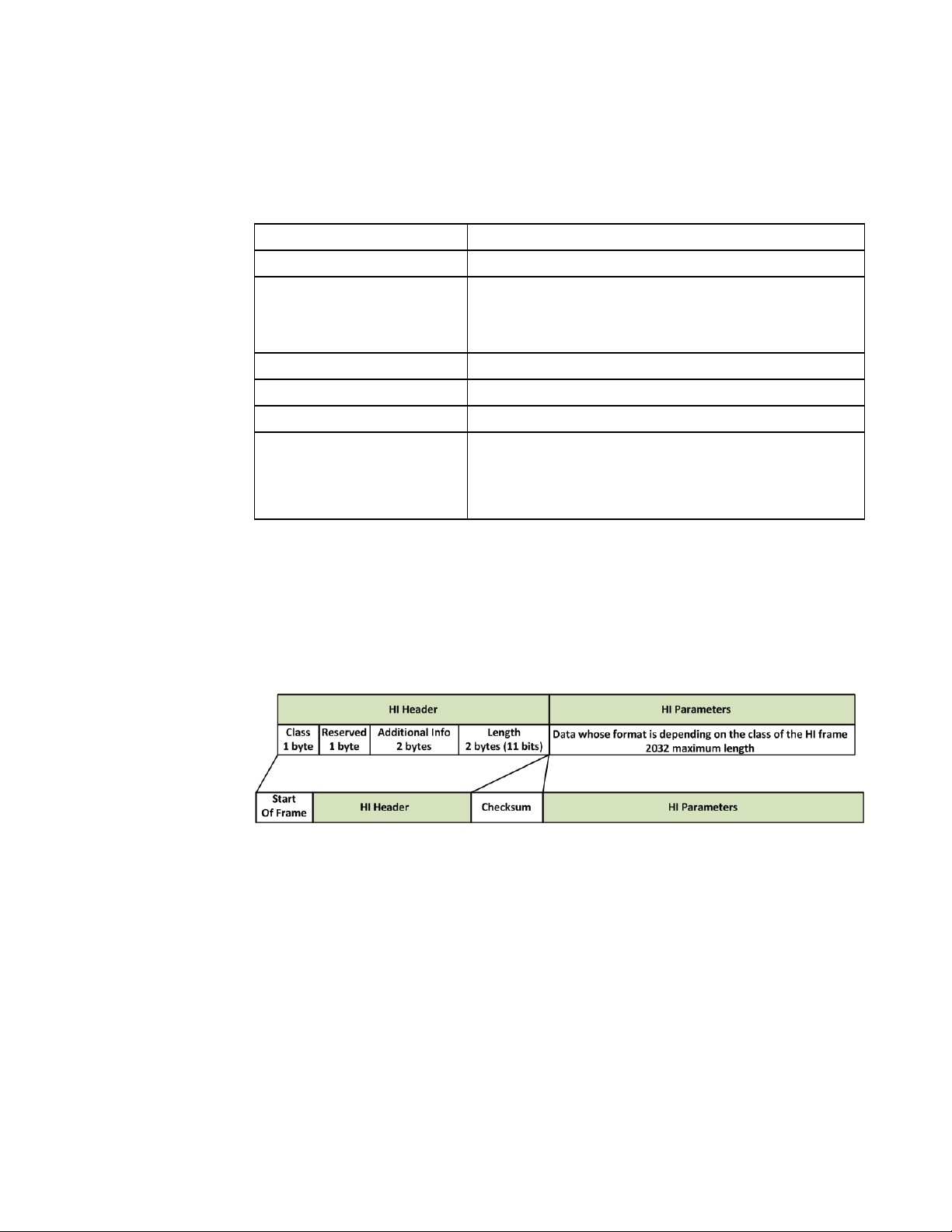
GS2200M IP2WiFi Adapter Command Reference Guide
The format of HI Parameters field is determined by the service class. The service class of
each frame is signaled by the value of the first field. Available service class identifiers (see
Table 20, page 53).
Table 20 HI Parameters Service Class Identifiers
Identifiers Description
Start of frame 0xA5
Class
Reserved 0x00
Additional Info 0x00,0x00
Length Maximum 2032
CheckSum
0x01 - WRITE_REQUEST from MCU side
0x02 - READ_REQUEST from MCU side
0x03 - DATA from MCU side
A single checksum byte is used, computed as the 1’s
complement of the 8-bit long (modulo-256) sum of all the
bytes of the HI HEADER (not including the Start
delimiter).
3.2.2.4 Annexure - HI Frame Response (From GS Node)
Figure 10, page 53 shows the HI Frame Response from GS node.
Figure 10 HI Frame Response (from GS Node)
Table 21, page 54 shows the HI Frame Response from GS node
1VV0301501 Rev.1.0 53 2018-03-12
Page 54

GS2200M IP2WiFi Adapter Command Reference Guide
Table 21 HI Frame Response (from GS Node)
Identifier Description
Start of frame 0xA5
Class
Reserved 0x00
Additional Info
Length 0 (No Data)
CheckSum
0x11 - WRITE_RESPONSE_OK to MCU side
0x12 - READ_RESPONSE_OK to MCU side
0x13 - WRITE_RESPONSE_NOK to MCU side
0x14 - READ_RESPONSE_NOK to MCU side
0x15 - DATA to MCU side
0x00,0x00
0x00, 0x01 - Pending Data for transfer from GS2000 to
MCU
A single checksum byte is used, computed as the 1’s
complement of the 8-bit long (modulo-256) sum of all the
bytes of the HI HEADER (not including the Start
delimiter).
3.2.2.5 Pin Connection for SPI Interface
Table 22, page 54 describes the pin connection for the SPI interface.
Table 22 Pin Connection for SPI Interface
Host MCU IP2WiFi Node Remarks
MSPI_DOUT SSPI_DIN N/A
MSPI_DIN SSPI_DOUT N/A
MSPI_SS SSPI_SS N/A
MSPI_CLK SSPI_CLK N/A
GPIO GPIO37 Host wake-up signal or Ready to Send.
Ground Ground Ground
1VV0301501 Rev.1.0 54 2018-03-12
Page 55

GS2200M IP2WiFi Adapter Command Reference Guide
3.2.3 SDIO Interface
GS node is supported to be configured as SDIO slave only. It uses the SDIO interface with
a maximum clock frequency of 33 MHz.
NOTE: There is no command available to configure SDIO interface. This
interface can be only enabled from the SDK Builder while compiling the
firmware.
3.2.3.1 Capabilities
1. Block size of 512 bytes
2. Data bus width of 4 bits
3. Maximum clock supported is 33Mhz
4. Support for Direct read/write (IO52) and Extended read/write (IO53) operations
5. IO Signals:
– SDIO_CLK: Clock
– SDIO_CMD: Command line
– SDIO_DAT0: is used for data transfer and busy signaling
– SDIO_DAT1: is used for data transfer and Interrupt signaling
– SDIO_DAT2: is used for data transfer and read_wait
– SDIO_DAT3: is used for data transfer
1VV0301501 Rev.1.0 55 2018-03-12
Page 56

GS2200M IP2WiFi Adapter Command Reference Guide
3.2.3.2 SDIO Host Slave Initialization and Communication
This section provides initialization steps to be performed by the Host (SDIO Master) after
power up.
NOTE: Before the Host powers up, GS node needs to be interfaced with Host via SDIO.
3.2.3.2.4 Host-SDIO Master Initialization
The following steps are performed to initialize Host-SDIO Master:
1. Initialization
– Set the SDIO clock to 400KHz
– Set the bus width to 1
– Set power state to ON
– Enable SDIO clock
– Enable card insert/remove interrupt
2. Wait for the card insert interrupt.
NOTE: Card insert interrupt happens only on a fresh insert. If present during boot, the
Host shall not wait for this interrupt.
3. Once step 2 occurs, perform the following: (Refer function io_sd_mount ())
– Set the clock frequency (low speed-400KHz) for card identification
– Wait for card wake up (100 msec/500msec/1sec)
– Send CMD52 to do a card reset (CMD52, fun0, address 0x06, value -> 0x08,
write)
– Send CMD5 and check for the error status
– If the above CMD returns no error, check number of IO functions
– Set the supported function number
– Send CMD5 with argument 0 to get OCR (Operations Condition Register), which
is used to inquire about the voltage range needed by the I/O card (GS node).
– Send CMD5 to write new voltage and keep sending it (this can be performed in a
loop for a maximum of 100 iterations) till it returns success
– Check the response and wait for the card ready.
– Send CMD3 with argument 0 to get RCA (Relative Card Address Register)
– Send CMD7 to change the state
– Read CCR register 0x13 to get the capability
– Depends on the capability enable high/low speed by setting corresponding clock.
1VV0301501 Rev.1.0 56 2018-03-12
Page 57

GS2200M IP2WiFi Adapter Command Reference Guide
– Set the 4bit/1 bit mode depends on the above capability
4. Write the CCR register 0x02 to enable the SDIO card.
5. Write the CCR register 0x04 to enable the card interrupt for a function
6. Write CCR register 0x110 and 0x111 to set the card block size
– Here, initialization at function 0x00 is done.
– Function 1 is used for read/write data from the card.
– Only two function 1 registers are accessible from the host
- One is the interrupt which indicates pending data at 0x05
- Other is the read count bytes at 0x1c -0x1d.
The following table describes the values of SDIO CCR registers before and after
initialization for reference.
Table 23 DIO CCR registers before and after initialization
S. No. Address Name Value
(Before)
1
2
3
4
5
6
7
8
9
10
11
12
13
14
15
16
17
18
19
20
0x00 CCCR/SDIO Version 0x32 0x32
0x01
SD Specification
Revision
0x02 0x02
0x02 I/O Enable 0x00 0x02
0x03 I/O Ready 0x00 0x02
0x04 Int Enable 0x00 0x03
0x05 Int Pending 0x00 0x02
0x06 I/O Abort 0x00 0x00
0x07 Bus Interface Control 0x02 0x02
0x08 Card Capability 0x1f 0x1f
0c09 Common CIS Pointer 0x00 0x00
0x0a Common CIS Pointer 0x10 0x10
0x0b Common CIS Pointer 0x00 0x00
0x0c Bus Suspend 0x00 0x00
0x0d Function Select 0x00 0x00
0x0e Exec Flags 0x00 0x00
0x0f Ready Flags 0x00 0x00
0x10 FN0 Block Size 0x00 0x00
0x11 FN0 Block Size 0x00 0x00
0x12 Power Control 0x01 0x01
0x13 High Speed 0x03 0x03
Value
(After)
1VV0301501 Rev.1.0 57 2018-03-12
Page 58

GS2200M IP2WiFi Adapter Command Reference Guide
3.2.3.2.5 Host Read Sequence
When GS node writes data to the Host, it receives read interrupt. Upon receiving the
interrupt following steps should be performed by the HOST.
• Check 'Interrupt Pending' register.
- Read Interrupt Pending register (function 0 address 0x05)
- If value is '0x02', it means there is an interrupt pending.
• Clear interrupt by reading ‘Int Enable’ register
- Read ‘Int Enable’ register (function 1 address 0x04) using CMD52).
• Re-Check 'Interrupt Pending' register to make sure interrupt has been cleared
- Read Interrupt Pending register (function 0 address 0x05)
- If value is '0x00', it means there is no pending interrupt.
• Read the data count (using CMD52).
– Read the value at address 0x1C with function 1, say len1
– Read the value at address 0x1D with function 1, say len2
– Compute the actual data length to be read using the following logic
act_len = len1| (len2 << 8);
• Read the data (using CMD53).
Figure 11 SDIO Block (Multiple) Read Operation
3.2.3.2.6 Host Write Sequence
• Check if the SDIO medium is available or not, by checking the ‘SDIO DAT0’ line.
– If LOW, keep polling till ‘SDIO DAT0’ goes HIGH
1VV0301501 Rev.1.0 58 2018-03-12
Page 59

GS2200M IP2WiFi Adapter Command Reference Guide
– If HIGH, continue with WRITE operation
• Issue CMD53 with respective arguments for writing the data to GS node.
NOTE: It is strongly recommended to send maximum of 1400 bytes in a single
write.
Figure 12 SDIO Block (Multiple) Write Operation
3.2.3.3 SDIO Host Recommendations
Following are recommendations which the embedded host (which acts as SDIO Master
when interfaced with GS node) needs to follow for efficiently handling specific scenarios,
maintaining and restoring the SDIO connection between Host MCU and GS node.
NOTE:
1.)Since SDIO slave initialization is dependent on HOST SDIO Master, it is
mandatory to setup the Host’s SDIO which is the Master before GS node
boots-up. If not GS node keeps waiting until SDIO Master initializes.
2.)If GS node is kept waiting until the WATCHDOG timer expires, then it would
result in WATCHDOG Reset.
3.2.3.3.7 SDIO_Busy Signal Handling
When SDIO buffer on GS node is full, it cannot receive more data from Host MCU. In such
cases, SDIO Slave on GS node pulls the SDIO_Busy line LOW to indicate that it cannot
1VV0301501 Rev.1.0 59 2018-03-12
Page 60

GS2200M IP2WiFi Adapter Command Reference Guide
receive any more data. At this point, Host MCU cannot perform WRITE and READ
operations as the SDIO CMD response returns failure.
To avoid WRITE and READ failures, Host needs to perform the following:
1. Check for SDIO_Busy signal, before initiating SDIO_WRITE.
2. If SDIO medium is busy, keep polling till the SDIO_Busy line is HIGH (SDIO
medium ready for communication).
3. If medium is not busy, go ahead with the WRITE.
NOTE: Host needs to ensure that it does not drop any data due to Busy signaling.
3.2.3.3.8 Handling Rx interrupt
When GS node has data (Command Response/Data/Asynchronous Message) to be sent to
Host MCU, Host needs to perform the following procedure to read data:
1. Interrupt line (DATA_1) goes low to trigger the host interrupt.
2. Host disables the interrupt and clears the interrupt status register.
3. Host reads the data length registers.
4. Host reads number of bytes specified by the data length registers.
5. After this point, DATA_1 goes high.
6. Host enables the interrupt again.
7. If GS node has more data to be sent to the host, interrupt line goes low again, and steps
3.2.3.3.9 Handling GS Reset
As SDIO interface does not support in-band notification from Slave (GS node) to Master
when there is an interface tear down (this can happen if the slave is put into an expected or
unexpected reset), following mechanism has to be incorporated in the Host MCU (SDIO
Master) to determine the event and re-initialize the SDIO block to establish the SYNC with
GS node.
The SD_LinkCheck mechanism in the Host MCU needs to perform the following:
1. Read ‘I/O Enable’ bit (addr: 0x02) in the CCR register. If the value is ZERO, then it is
1 to 6 are repeated.
a reset.
2. Read ‘I/O Ready’ bit (address: 0x03) in CCR. If the value is ZERO, then it is a reset.
1VV0301501 Rev.1.0 60 2018-03-12
Page 61

GS2200M IP2WiFi Adapter Command Reference Guide
3.2.3.4 Pin Description
The following are the pin descriptions in GS module:
Table 24 Pin Descriptions
Pin DIR Description
GPIO_35/SDIO_CLK/SPI0_CLK IN SDIO Clock/ SPI0 Clock
GPIO_34/SDIO_CMD/SPI0_DIN IN SD4 bit mode, command line
SD1 bit mode, command line
SPI mode, Data input
GPIO_37/SDIO_DAT1_INT IN/OUT
GPIO_32/SDIO_DAT2 IN/OUT SD4 bit mode, Data line 2
GPIO_33/SDIO_DAT3/SPI0_CS_n_0 IN/OUT SD4 bit mode, Data line 3
GPIO_36/SDIO_DAT0/SPI0_DOUT IN/OUT SD4 bit mode, Data line 0
3.2.4 Interface Verification
The command AT can be issued to verify that the interface is operating correctly or not.
Command Syntax AT
SD4 bit mode, Data line
1/Interrupt
SD1 bit mode, Interrupt
SPI mode, Interrupt
SD1 bit mode, not used
SPI mode, Data input
SD1 bit mode, not used
SPI mode, Chip Select
SD1 bit mode, Data line
SPI mode, Data Output
Synchronous Response
Table 25, page 61 describes the synchronous responses and remarks for the Interface
Verification command.
Table 25 Interface Verification Synchronous Responses
Responses Remarks
OK Success
Failure
No response
1VV0301501 Rev.1.0 61 2018-03-12
Interface not operating correctly.
Page 62

GS2200M IP2WiFi Adapter Command Reference Guide
1VV0301501 Rev.1.0 62 2018-03-12
Page 63

GS2200M IP2WiFi Adapter Command Reference Guide
Chapter 4 General Operations
This chapter describes the commands for generic operations as required by IP-to-WiFi
Application.
• Version, page 63
• Time Setting, page 65
• Profile Setting, page 67
• Reset, page 98
• MAC, page 76
4.1 Version
This command is used to return version information.
Command Syntax AT+VER=?
Response
– IP-to-WiFi version
– GainSpan Embedded Platform Software version
– WLAN firmware version
Example 1 AT+VER=?
IP2WiFi APP VERSION=5.1.4
IP2WiFi GEPS VERSION=5.1.4
IP2WiFi WLAN VERSION=5.1.4
OK
The command to get more details of the IP2WiFi version.
AT+VER=??
Response
This command returns more information along with the above response of the IP2WiFi
binary followed by the standard command response to the serial host.
– IP-to-WiFi version
– GainSpan Embedded Platform Software version
– WLAN firmware version
– IP-to-WiFi binary type as specified in SDK builder
– IP-to-WiFi Release type which can be GA or Beta
1VV0301501 Rev.1.0 63 2018-03-12
Page 64

GS2200M IP2WiFi Adapter Command Reference Guide
– Build time
– Build date
– WLAN firmware extension version
– Application firmware extension version
– WLAN feature bitmap
– GEPS firmware extension version
– Module flash ID with storage capacity
Example 2 AT+VER=??
IP2WiFi APP VERSION=5.1.4
IP2WiFi GEPS VERSION=5.1.4
IP2WiFi WLAN VERSION=5.1.4
IP2WiFi BIN TYPE=5_1_4_Unsolicited_Tx
IP2WiFi RELEASE TYPE=GA
BUILD TIME=03:33:28
BUILD DATE=Jan 27 2015
WLAN EXT VERSION=5
IP2WiFi APP EXT VERSION=1
WLAN FEAT BMAP=0000000000000007
GEPS EXT VERSION=1
FLASH ID=0x000020c2:MICRONIX-4MB
OK
1VV0301501 Rev.1.0 64 2018-03-12
Page 65

GS2200M IP2WiFi Adapter Command Reference Guide
4.2 Time Setting
4.2.1 Set System Time
4.2.1.1 Manual Setting
This command is used to set the GS node’s system time to the time specified as the
parameters and returns the standard command response. GS node expects either one of the
time parameters.
Command Syntax AT+SETTIME=[<dd/mm/yyyy>,<HH:MM:SS>][,System time in
milliseconds since epoch (1970)]
Parameter Description
Table 26, page 65 describes the Set System Time parameters.
Table 26 Set System Time Parameters
Parameter Optional/Mandatory Description
dd/mm/yyyy Mandatory It specifies the date in dd/mm/yyyy format.
HH:MM:SS Mandatory It specifies the time in HH:MM:SS format.
System time in
milliseconds since epoch
(1970)
Synchronous Response
Optional
It specifies the system time in milliseconds
since epoch (1970).
Table 27, page 65 describes the synchronous responses and remarks for the Set System
Time command.
Table 27 Set System Time Synchronous Responses
Responses Remarks
OK Success
ERROR:INVALID INPUT For invalid input
Example -1 AT+SETTIME=02/06/2016,15:00:00
OK
Example -2 AT+SETTIME=,1493788674000
OK
AT+GETTIME=?
3/5/2017,5:17:58,1493788678792
OK
Example
1VV0301501 Rev.1.0 65 2018-03-12
Page 66

GS2200M IP2WiFi Adapter Command Reference Guide
4.2.2 Get System Time
This command is used to receive the current system time in milliseconds since epoch
(1970) followed by the standard command response to the serial interface.
Command Syntax AT+GETTIME=?
Synchronous Response
Table 28, page 66 describes the synchronous responses and remarks for the Get System
Time command.
Table 28 Get System Time Synchronous Responses
Responses Remarks
<dd/mm/yyyy>,<HH:MM:SS>
ERROR:INVALID INPUT For invalid input
Example 1 AT+GETTIME=?
2/6/2016,15:0:7,1464879607040
Success
Displays date and time in the provided format.
OK
Example 2 Serial2WiFi APP
AT+TCERTADD=SSL_comodo,0,1500,1
OK
OK
AT+CERTINFOGET=SSL_comodo
ERROR: INVALID INPUT
AT+CERTINFOGET=SSL_comodo
cert->not_before: 1263859200
cert->not_after: 2147471999
valid from: Tue, 19 Jan 2010 00:00:00 GMT
valid till: Fri, 13 Dec 1901 17:31:43 GMT
OK
1VV0301501 Rev.1.0 66 2018-03-12
Page 67

GS2200M IP2WiFi Adapter Command Reference Guide
4.3 Profile Setting
GS node supports different operating modes with various settings pre-configured to work
with the system. A pre-defined set of variables can be stored in a profile. GS node currently
supports storing two different profiles (profile0 and profile1).
The following AT commands are sequentially executed for setting a profile:
– AT&V - To view the current profile
– AT&W - To write to profile settings
– ATZn - To load a profile
– AT&Y - To reboot with particular profile
– AT&F - To factory Reset
4.3.1 Get Profile
This command is used to get the information of current profiles (Profile 0 and Profile 1) and
their saved parameter values in ASCII format. The details of profile parameters are
described in 4.3.2 Save Profile, page 68.
Command Syntax AT&V
Synchronous Response
Table 29, page 67 describes the synchronous responses and remarks for the Get profile
command.
OK Success
Table 29 Get Profile Synchronous Responses
Responses Remarks
1VV0301501 Rev.1.0 67 2018-03-12
Page 68

GS2200M IP2WiFi Adapter Command Reference Guide
4.3.2 Save Profile
This command is used to save the current profile. Upon deployment of this command, the
current configuration settings are stored in non-volatile memory under the specified profile,
(profile 0, or profile 1). In order to ensure that these parameters are restored after power
cycling the GS node, the command AT&Y must also be issued, using the same profile
number selected here.
Command Syntax AT&Wn
Parameter Description
Table 30, page 68 describes the Save Profile parameters.
Table 30 Save Profile Parameters
Parameter Optional/Mandatory Value Description
0 For profile 0
n Mandatory
Synchronous Response
1 For profile 1
Saves the profile specified by n (0 or 1).
Table 31, page 68 describes the synchronous responses and remarks for the Save Profile
command.
Table 31 Save Profile Synchronous Responses
Responses Remarks
OK Success
If parameters are not valid.
ERROR:INVALID INPUT
NOTE: GS node supports two profiles.
(n value is other than 0 or 1)
1VV0301501 Rev.1.0 68 2018-03-12
Page 69

GS2200M IP2WiFi Adapter Command Reference Guide
4.3.3 Load Profile
This command is used to load a profile. Upon deployment of this command, the currently
configured settings are overwritten by those stored in non-volatile memory under the
specified profile.
Command Syntax ATZn
Parameter Description
Table 32, page 69 describes the Load Profile parameters.
Table 32 Load Profile Parameters
Parameter Optional/Mandatory Value Description
0 For profile 0
n Mandatory
Synchronous Response
1 For profile 1
Load the profile specified by n (0 or 1).
Table 33, page 69 describes the synchronous responses and remarks for the Load Profile
command.
Table 33 Load Profile Synchronous Responses
Responses Remarks
OK Success
If parameters are not valid.
ERROR:INVALID INPUT
(n value is other than 0 or 1)
1VV0301501 Rev.1.0 69 2018-03-12
Page 70

GS2200M IP2WiFi Adapter Command Reference Guide
4.3.4 Select Default Profile
This command is used to select the default profile. The settings from the profile that are
chosen as the default profile are loaded from non-volatile memory when the device is
started.
Command Syntax AT&Yn
Parameter Description
Table 34, page 70 describes the Select Default Profile parameters.
Table 34 Select Default Profile Parameters
Parameter Optional/Mandatory Value Description
0 For profile 0
n Mandatory
Synchronous Response
Table 35, page 70 describes the synchronous responses and remarks for the Select Default
Profile command.
OK Success
ERROR:INVALID INPUT
Example AT&Y0
OK
1 For profile 1
Set default profile to the value n (0 or 1).
Table 35 Select Default Profile Synchronous Responses
Responses Remarks
If parameters are not valid.
(n value is other than 0 or 1)
1VV0301501 Rev.1.0 70 2018-03-12
Page 71

GS2200M IP2WiFi Adapter Command Reference Guide
4.3.5 Restore Profile
This command is used to restore current profile to factory default values. The factory
default values are stored in RAM, and will be lost after each power cycle.
Upon deployment of this command, the current configuration variables are reset to the
factory defaults. These defaults are defined by macro values in the configuration header.
Issuing this command resets essentially all configuration variables.
Command Syntax AT&F
Synchronous Response
Table 36, page 71 describes the synchronous responses and remarks for the Restore Profile
command.
Table 36 Restore Profile Synchronous Responses
Responses Remarks
OK Success
NOTE: The following sequence of AT Commands is used for complete Factory
restore:
AT&Y0
AT&F
AT&W0
AT&Y1
AT&F
AT&W1
AT+RESET=1
4.3.6 Define Profile
The configuration parameter values that define the behavior of the GS node are grouped
into Profiles. These profiles are stored in non-volatile memory when not in use. The default
configuration supports single Profile. The contents of a profile are listed in Table 37,
page 71.
Parameter Values Reference
General Wireless Parameter
Table 37 Define Profile Parameters
802.11 Operating Mode STA, Limited AP 5.1.2 Operation Mode, page 83
Transmit Power Configuration N/A
802.11 Transmit Retry Count 5.1.3 MAC Retry, page 86
Power Save Mode Enabled, Disabled
6.1.3 Custom Power Save Radio Receive,
page 148
1VV0301501 Rev.1.0 71 2018-03-12
Page 72

GS2200M IP2WiFi Adapter Command Reference Guide
Table 37 Define Profile Parameters (Continued)
Parameter Values Reference
802.11 Radio Mode Enabled, Disabled 6.1.1 Active Radio Receive, page 143
Wireless Interface Security Configuration
Authentication Mode Open, Shared 5.3.8 Advanced Commands, page 122
PSK Valid Valid, Invalid
5.3.3.5 WPA-PSK and WPA2-PSK Key
PSK-SSID
Any valid SSID, used for
PSK key computation
Calculation, page 112
WEP Key Configuration 5.3.8 Advanced Commands, page 122
WPA Pass Phrase
5.3.3.4 WPA-PSK and WPA2-PSK Passphrase,
page 111
UART Configuration
Echo Mode Enabled, Disabled 8.3.2 Echo, page 188
Verbose Mode Enabled, Disabled 8.3.3 Verbose, page 189
Bits Per Character 5, 6, 7, 8
3.2.1.1 UART Parameters, page 35Number of Stop Bits 1, 2
Parity Type None, Odd, Even
Software Flow Control Mode Enabled, Disabled 3.2.1.2 Software Flow Control, page 37
Hardware Flow Control Mode Enabled, Disabled 3.2.1.3 Hardware Flow Control, page 38
Baud Rate 3.2.1.1 UART Parameters, page 35
1VV0301501 Rev.1.0 72 2018-03-12
Page 73

GS2200M IP2WiFi Adapter Command Reference Guide
4.3.7 Identification Information
This command is used to return various identification information of GS node.
Command Syntax ATIn
Parameter Description
Table 38, page 73 describes the Identification Information parameters.
Table 38 Identification Information Parameters
Parameter Optional/Mandatory Value Description
0 OEM identification
1 Hardware version
n Mandatory
n is the information ID to obtain. These responses are provided as
ASCII strings in addition to the standard command response.
2 Software version
Synchronous Response
Table 39, page 73 describes the synchronous responses and remarks for the Identification
Information command.
Table 39 Identification Information Synchronous Responses
Responses Remarks
GainSpan OK Success
ATI1:GSxxxx
OK
ATI2:x.x.x
OK
The hardware version will change whenever the code
in the ROM gets changed.
The software version will change whenever a new
feature is added.
If parameters are not valid.
ERROR:INVALID INPUT
(n value is other than 0-2)
1VV0301501 Rev.1.0 73 2018-03-12
Page 74

GS2200M IP2WiFi Adapter Command Reference Guide
4.3.8 Enhanced Asynchronous Notification
This command is used to support enhanced asynchronous notification method.
Command Syntax AT+ASYNCMSGFMT=n
Parameter Description
Table 40, page 74 describes the Enhanced Asynchronous Notification parameters.
Table 40 Enhanced Asynchronous Notification Parameters
Parameter Optional/Mandatory Value Description
n Mandatory
0 (default) Disable this feature
1 Enable this feature
Enabling this feature results with all asynchronous message going to the serial interface with a header. Also during
these asynchronous message transfer IP2WiFi Application makes the GPIO19 high. Node Start Up Handling.
The asynchronous message format is as shown:
<ESC><TYPE><SUBTYPE><LENGTH><MESSAGE>
<ESC> Escape
TYPE
Type of message and the length is one byte. For asynchronous
message, it is 0x41 (ASCII value A)
Message subtype and the length of this field is:
Format
SUBTYPE
• One byte when the value of this byte is one of the values from 0 to E.
• Two bytes when the value of this byte is F where the first byte and the
next byte is read and interpreted as per the table in
A.2 Asynchronous & Enhanced Asynchronous Messages,
page 195
.
Length of the asynchronous message in hex. This field length is 2
LENGTH
bytes. See A.2 Asynchronous & Enhanced Asynchronous
Messages, page 195.
MESSAGE Exact asynchronous message as string.
Synchronous Response
Table 41, page 74 describes the synchronous responses and remarks for Enhanced
Asynchronous command.
Table 41 Enhanced Asynchronous Notification Synchronous Responses
Responses Remarks
OK Success
If parameters are not valid.
ERROR: INVALID INPUT
1VV0301501 Rev.1.0 74 2018-03-12
(If n value is other than 0 and 1)
Page 75

GS2200M IP2WiFi Adapter Command Reference Guide
4.4 Reset
This command is used to reset the GS node. When this command is used without parameter
(AT+RESET), it forcefully resets the module core and comes out with a fresh boot message
“APP Reset-APP SW Reset”.
Command Syntax AT+RESET
NOTE: This command without parameter (AT+RESET) is obsolete and it is
retained for backward compatibility.
Command Syntax AT+RESET=n
NOTE: It is recommended to use this command with parameter (AT+RESET=1).
Parameter Description
Table 42, page 75 describes the Reset parameters.
Table 42 Reset Parameters
Parameter Optional/Mandatory Value Description
1:Resets the whole system including the RTC
n Optional
Value range: 1,2
Format: Decimal
domain.
2: Resets and restores the system to factory
default setting
1VV0301501 Rev.1.0 75 2018-03-12
Page 76

GS2200M IP2WiFi Adapter Command Reference Guide
4.5 MAC
All new GainSpan modules will have “00:21:7E:xx:xx:xx” as MAC address with Telit
Organizational Unique Identifier (OUI).
4.5.1 Set MAC Address
NOTE: This command is obsolete as GS node uses the MAC address from OTP.
It is retained for backward compatibility.
This command is used to set a MAC address to the GS node.
The MAC address is used in the 802.11 protocol to identify the various nodes
communicating with an Access Point and to route messages within the local area (layer 2)
network. Fixed MAC addresses issued to network interfaces are hierarchically structured
and are intended to be globally unique. Before issuing a MAC address to a given GS node,
ensure that no other local device is using that address.
NOTE:
1.) The GS node is stored with two MAC addresses. One when it is in STA mode
and the other when it is in AP mode.
The MAC address printed on the GS node is for STA mode.
STA MAC address + 1 is the MAC address for AP mode.
2.) To set the MAC address for the GS node in STA mode, execute the command
AT+WM=0 followed by the AT+NMAC=<MAC ADDRESS> command.
3.) To set the MAC address for the GS node in AP mode, execute the command
AT+WM=2 followed by the AT+NMAC=<MAC ADDRESS> command.
Command Syntax AT+NMAC=<MAC ADDRESS>
Parameter Description
Table 43, page 76 describes the Selection of Set MAC Address parameters.
Table 43 Set MAC Address Parameters
Parameter Optional/Mandatory Value Description
The format of the MAC address is a 17
character colon-delimited hexadecimal
MAC Address Mandatory
xx:xx:xx:xx:xx:xx
(17 characters)
number. The MAC address supplied is saved
to Flash memory, and will be used on each
subsequent cold boot (from power Off) or
warm boot (from Standby).
Synchronous Response
1VV0301501 Rev.1.0 76 2018-03-12
Page 77

GS2200M IP2WiFi Adapter Command Reference Guide
Table 44, page 77 describes the synchronous responses and remarks for the Set MAC
Address command.
Table 44 Set MAC Address Synchronous Responses
Responses Remarks
OK Success
ERROR:INVALID INPUT If value is not in the valid format.
Example 1 To set the MAC address for the GS node in STA mode, execute the following sequence of
commands:
AT+WM=0
OK
AT+NMAC=00:1d:c9:d0:70:cc
OK
AT+NMAC=?
00:1d:c9:d0:70:cc
OK
Example 2 To set the MAC address for the GS node in AP mode, execute the following sequence of
commands:
AT+WM=2
OK
AT+NMAC=00:1d:c9:d0:70:cc
OK
AT+NMAC=?
00:1d:c9:d0:70:cc
OK
NOTE: The command AT+WM=2 should not be issued while the AP is already
operating as the limited AP stops beaconing.
1VV0301501 Rev.1.0 77 2018-03-12
Page 78

GS2200M IP2WiFi Adapter Command Reference Guide
4.5.2 Get MAC Address
This command is used to output the current MAC address of the wireless interface to the
serial port.
NOTE:
1.) The GS node is stored with two MAC addresses. One when it is in STA mode
and the other when it is in AP mode.
The MAC address printed on the GS node is for STA mode.
STA MAC address + 1 is the MAC address for AP mode.
2.) To get the current MAC address for the GS node in STA mode, execute the
command AT+WM=0 followed by the AT+NMAC=? command.
3.) To get the current MAC address for the GS node in AP mode, execute the
command AT+WM=2 followed by the AT+NMAC=? command.
Command Syntax AT+NMAC=?
Synchronous Response
Table 45, page 78 describes the synchronous responses and remarks for the Get MAC
Address command.
Table 45 Get MAC Address Synchronous Responses
Responses Remarks
OK Success
Example 1 To get the current MAC address for the GS node in STA mode, execute the following
sequence of commands:
AT+WM=0
OK
AT+NMAC=?
00:1d:c9:d0:70:cc
OK
Example 2 To get the current MAC address for the GS node in AP mode, execute the following
sequence of commands:
AT+WM=2
OK
AT+NMAC=?
00:1d:c9:d0:70:cc
OK
1VV0301501 Rev.1.0 78 2018-03-12
Page 79

GS2200M IP2WiFi Adapter Command Reference Guide
1VV0301501 Rev.1.0 79 2018-03-12
Page 80

GS2200M IP2WiFi Adapter Command Reference Guide
1VV0301501 Rev.1.0 80 2018-03-12
Page 81

GS2200M IP2WiFi Adapter Command Reference Guide
Chapter 5 Wireless
This chapter describes commands for configurations and operations related to WLAN
layer.
• Wireless Generic, page 81
• Beacon Mode (Unassociated Mode), page 93
• Station/AP Mode, page 104
• WiFi Direct Mode, page 123
5.1 Wireless Generic
5.1.1 Regulatory Domain
5.1.1.1 Set Regulatory Domain
This command is used to configure the GS node’s parameters to the requested regulatory
domain.
Command Syntax AT+WREGDOMAIN=<Regulartory Domain>
NOTE: We recommend setting the regulatory domain using SDK builder. If it is
not set using SDK builder or if it needs to be changed, this should be the first
command issued after the IP-to-WiFi prompt. This will automatically save the
information in the profile.
Parameter Description
Table 46, page 82 describes the Set Regulatory Domain parameters.
1VV0301501 Rev. 1.0 81 2018-03-12
Page 82

GS2200M IP2WiFi Adapter Command Reference Guide
Table 46 Set Regulatory Domain Parameters
Parameter Optional/
Mandatory
Regulatory Domain Mandatory
Synchronous Response
Table 47, page 82 describes the synchronous responses and remarks for the Set Regulatory
Domain command.
OK Success
ERROR:INVALID INPUT
Value Regulatory
Domain
Supported
Channels
Desired Power Level
Internal PA
(0 as default)
External PA
(2 as default)
0 (default) FCC 1 to 11 0-7 2-15
1 ETSI 1 to 13 0-7 4-15
2 TELEC 1 to 14 0-7 2-15
The Regulatory domain set is required only once since it is being updated in the
Flash.
Table 47 Set Regulatory Domain Synchronous Responses
Responses Remarks
If parameters are not valid.
(If Register domain value is other than 0-3)
5.1.1.2 Get Regulatory Domain
This command is used to output the current regulatory domain of the wireless interface to
the serial port.
Command Syntax AT+WREGDOMAIN=?
Synchronous Response
Table 48, page 82 describes the synchronous responses and remarks for the Get Regulatory
Domain command.
Table 48 Get Regulatory Domain Synchronous Responses
REG_DOMAIN=FCC
OK
Example AT+WREGDOMAIN=?
REG_DOMAIN=FCC
OK
Where possible values of REG_DOMAIN are: FCC, ETSI, TELEC
Responses Remarks
Success
1VV0301501 Rev. 1.0 82 2018-03-12
Page 83

GS2200M IP2WiFi Adapter Command Reference Guide
5.1.2 Operation Mode
This command is used to set the wireless mode and related parameters.
Command Syntax AT+WM=<wireless mode>[,<beacon interval in LAP
mode>,<broadcast ssid in LAP mode>,
<no. of stations allowed in LAP mode>,<DTIM period in LAP
mode>,<inactivity timeout in LAP mode>,<reserved>,<rate
adaptation-device type>,<rate adaptation-minimum
application throughput>]<CR>
NOTE: Do not issue AT+WA command when GS node is in WiFi direct (P2P)
mode. To issue AT+WA command, switch the GS node to either Station mode or
Limited-AP mode using AT+WM command.
Parameter Description
Table 49, page 83 describes the parameters in Mode.
Table 49 Mode Parameters
Parameter Optional/Mandatory Value Description
0: WiFi station mode
1: Reserved
wireless mode Mandatory
2: WiFi limited AP
mode
3: WiFi direct
mode(P2P)
4: Reserved
6: Provisioning AP
It specifies the wireless mode to be set.
Note: When this parameter is set to 3, do
not issue AT+WA command. To issue
AT+WA command, set this parameter to
either 0 (Station mode) or 2 (Limited-AP
mode).
mode
Default value not
applicable
beacon interval in
LAP mode
Optional
50 to 1500
Unit: milliseconds
Default value: 100ms
Time between two successive beacon
frames transmitted by the Limited AP
mode.
0- Beacon frames will contain SSID
information.
1- Beacon frames will not contain SSID
information (stealth mode).
It specifies whether to broadcast SSID in
the beacon frames or not (only applicable in
limited AP mode).
broadcast SSID in
LAP mode
Optional
0, 1
0: Enable
1: Disable
Default value: 0
Note: If WPS Registrar functionality is
required, do not disable SSID broadcast.
1VV0301501 Rev. 1.0 83 2018-03-12
Page 84

GS2200M IP2WiFi Adapter Command Reference Guide
Table 49 Mode Parameters
Parameter Optional/Mandatory Value Description
1 - 16
No. of stations
allowed to associate
in LAP mode
Optional
Minimum value: 1
Maximum value: 16
This configures the upper limit on the
number of STAs to be allowed to associate
when GS2000 is acting as LAP.
Default value: 8
It specifies the DTIM period in AP mode.
Value to be as minimum as possible. Unit is
DTIM period in LAP
mode
Optional
Minimum value: 1
Maximum value: 255
Default value: 3
in beacon intervals.
For more information, refer 802.11
specification.
Note: Recommended to configure this
value as small as possible.
This value specifies the inactivity time out
per STA, after which LAP send a
NULL/QoS-NULL frame expecting the
STA to MAC level acknowledge it.
When there is no activity from a connected
node, the module waits for 360 seconds and
sends a probe to the inactive node. If there
is no response, then it disconnects itself
from the inactive node.GS2000 does not
inactivity time-out in
LAP mode
Optional
Minimum value: 1
Maximum value:
65535
Default value: 360
Unit: seconds
send disassociation frame to STA.
Note: GS2000 doesn't send dis-association
frame to STA.
reserved Optional NA NA
It helps the WLAN subsystem in fine
tuning the chosen rate adaptation.
The rate adaptation algorithm depends on
the following application profiles:
Ultra low power profile: This profile
concentrates on saving power as it uses
battery powered devices and they have
strict battery life.
Throughput profile: This profile has a
requirement of minimum throughput as it
uses line powered or battery powered
rate
adaptation-device
type
Optional
0,1
0: Battery powered
/Ultra low power
profile
1: Line
powered/Throughput
profile
0(default)
devices without a stringent battery life.
Note:
1VV0301501 Rev. 1.0 84 2018-03-12
Page 85

GS2200M IP2WiFi Adapter Command Reference Guide
Table 49 Mode Parameters
Parameter Optional/Mandatory Value Description
rate
adaptation-minimum
application
throughput
Optional
0-22 Mbps
Default value: 0
rate adaptation algorithm.
Note: If rate adaptation - device type is
chosen as 0, then this parameter should be
set to 0.
Note:
1.) Minimum throughput is very much dependent on TCP/UDP.
2.) Rate adaptation-device type and rate adaptation-minimum application throughput parameter is to be provided,
since both go in pair
3.) These parameters are only a guidance to WLAN. The system tries to achieve it but it may not be always
achievable due to various circumstances such as WiFi environments, application use case, and so on.
This is used to derive minimum PHY rate in
Synchronous Response
Table 50, page 85 describes the synchronous responses and remarks for the Mode
command.
Table 50 Mode Synchronous Responses
Events Verbose mode Non Verbose mode Remarks
Success <CR><LF>OK<CR><LF> <CR><LF>OK<CR><LF> All parameters are valid
Failure
Example 1 Configure device in STA mode
<CR><LF>ERROR:<SP>INVALID<SP>I
NPUT<CR><LF>
AT+WM=0
Configure device in Limited-AP mode (default configuration)
<CR><LF>2<CR><LF>
Parameters are invalid or in
incorrect format.
AT+WM=2
Example 2 Configure device in Limited-AP mode, with following configuration:
AT+WM=2, , ,16,1, , ,1,5
Number of stations allowed to associate in Limited-AP mode = 16
DTIM period in LAP mode=1
Device type = Line powered
Minimum application throughput = 5mbps
Configure the device in LAP mode with 10 seconds as inactivity
AT+WM,,,,,10
Example 3 Configure the device in P2P mode
At+WM=3
1VV0301501 Rev. 1.0 85 2018-03-12
Page 86

GS2200M IP2WiFi Adapter Command Reference Guide
5.1.3 MAC Retry
This command is used to set the current retry count set to the supplied value.
Command Syntax AT+WRETRY=<n>
Parameter Description
Table 51, page 86 describes the Set Retry Count parameters.
Table 51 Set Retry Count Parameters
Parameter Optional/Mandatory Value Description
The current wireless retry count is set to the
n Mandatory
Default value - 8
Note: The count includes the initial transmission attempt.
1 to 255
supplied value. The transmission retry
count determines the maximum number of
times a data packet is retransmitted, if an
802.11 ACK is not received.
Synchronous Response
Table 52, page 86 describes the synchronous responses and remarks for the Set Retry Count
command.
Table 52 Set Retry Count Synchronous Responses
Responses Remarks
OK Success
ERROR:INVALID INPUT
Example AT+WRETRY=5
OK
If parameters are not valid
(If value is more than 1 to 255)
1VV0301501 Rev. 1.0 86 2018-03-12
Page 87

GS2200M IP2WiFi Adapter Command Reference Guide
5.1.4 Sync Loss Interval
This command is used to set the GS node for sync loss interval for n times the beacon
interval so that if the GS node does not receive the beacon for this time, it informs the user
this event is “Disassociation event.”
Command Syntax AT+WSYNCINTRL=<n>
Parameter Description
Table 53, page 87 describes the Sync Loss Interval parameters.
Table 53 Sync Loss Interval Parameters
Parameter Optional/Mandatory Value Description
This parameter specifies the beacon count. Time
difference between two beacons are approximately
100msec.
Example: If n=30 and 30 consecutive beacons are
missed then, SYNC loss is detected and GS node sends
the Disassociation packet to the Access Point.
The time taken for detecting sync loss for n=30 is
approximately 3seconds (30*100msec).
n Mandatory
Value range:
1-63325
Default
value: 100
Synchronous Response
Table 54, page 87 describes the synchronous responses and remarks for the Sync Loss
Interval command.
Asynchronous Response
Table 55, page 88 describes the asynchronous responses and remarks for the Sync Loss
Interval command.
Table 54 Sync Loss Interval Synchronous Responses
Responses Remarks
OK Success
ERROR:INVALID INPUT Invalid parameter (out of range)
1VV0301501 Rev. 1.0 87 2018-03-12
Page 88

GS2200M IP2WiFi Adapter Command Reference Guide
Table 55 Sync Loss Interval Asynchronous Responses
Responses Remarks
314Disassociation Event
Where,
Subtype - 3
Length - 14 (ASCII equivalent decimal is 20 characters, i.e.,
length of the actual message)
GS node does not receive beacons for this time
informs the user with this message.
Actual message - Disassociation Event
The type of message. Length is 1 byte. for asynchronous
message, it is 0x41 (ASCII value A).
Note: <ESC> and Type is not displayed because its Tera Term issue.
Example AT+WSYNCINTRL=500
If 500 consecutive beacons are missed then, SYNC loss is detected and GS node sends the
Disassociation packet to the Access Point.
The time taken for detecting sync loss in this case is approximately 50seconds (500
*100msec).
5.1.5 Set RTS Threshold
This command is used to set the RTS threshold value.
Command Syntax AT+WRTS=<RTSTHRESHOLD>[,TXOP ENABLE]
Parameter Description
Table 56, page 88 describes the RTS Threshold parameters.
Table 56 RTS Threshold Parameters
Parameter Optional/Mandatory Value Description
This parameter specifies the RTS/CTS
threshold.
When this parameter is set to one of the
values from 0 to 2999, it is considered as
RTS threshold.
Note: When this parameter is set to a
value >=3000, self CTS is enabled.
RTSTHRESHOLD Mandatory
0 to 2999
Default value - 0
TXOP ENABLE Optional N/A Reserved for future use.
Synchronous Response
Table 57, page 89 describes the synchronous responses and remarks for the RTS Threshold
command.
1VV0301501 Rev. 1.0 88 2018-03-12
Page 89

GS2200M IP2WiFi Adapter Command Reference Guide
Table 57 RTS Threshold Synchronous Responses
Responses Remarks
OK Success
Example AT+WRTS=0
OK
5.1.6 Transmit Data Rate
NOTE: These commands are obsolete and they are retained for backward
compatibility. It is recommended to use the default dynamic rate selection.
5.1.6.1 Set Transmit Rate
This command is used to set the transmit rate.
NOTE: This command is used for testing and debug purposes only. It is not fully
functional and it is not tested for higher rates.
Command Syntax AT+WRATE=<Transmit rate of data frame>[,<Transmit rate of
management frame>,<Transmit rate of control frame>]
Command Note If you want to set the transmission rate to 11Mbps, then you will need to give the value as
22.
Example AT+WRATE=22
Parameter Description
Table 58, page 90 describes the Set Transmit Rate parameters.
1VV0301501 Rev. 1.0 89 2018-03-12
Page 90

GS2200M IP2WiFi Adapter Command Reference Guide
Table 58 Set Transmit Rate Parameters
Parameter Optional/Mandatory Value Corresponding
Transmission
Rate
2 1 MBPS
4 2 MBPS
11 5.5 MBPS
13 6.5 MBPS
12 6 MBPS
18 9 MBPS
22 11 MBPS
24 12 MBPS
36 18 MBPS
Transmit rate of
data frame
Mandatory
39 19.5 MBPS
48 24 MBPS
52 26 MBPS
72 36 MBPS
78 39 MBPS
96 48 MBPS
Description
This parameter specifies the
transmission rate for data frames.
If only this parameter is provided
in the command, then the same
value is copied for the remaining
parameters Transmit rate of
management frame and
Transmit rate of control frame.
Transmit rate of
management
frame
Transmit rate of
control frame
Optional
Optional
104 52 MBPS
108 54 MBPS
117 58.5 MBPS
130 65 MBPS
Refer to the values and
corresponding transmission rates in
Transmit rate of data frame.
This parameter specifies the
transmission rate for
management frames.
This parameter specifies the
transmission rate for control
frames.
1VV0301501 Rev. 1.0 90 2018-03-12
Page 91

GS2200M IP2WiFi Adapter Command Reference Guide
Synchronous Response
Table 59, page 91 describes the synchronous responses and remarks for the Set Transmit
Rate command.
Table 59 Set Transmit Rate Synchronous Responses
Responses Remarks
OK Success
ERROR:INVALID INPUT
Example AT+WRATE=2
OK
5.1.6.2 Get Transmit Rate
This command is used to obtain the current transmit rate (in ASCII format) of the data
frame.
If parameters are not valid
(if value is other than above specified value)
NOTE: This command is used for testing and debug purposes only. It is not fully
functional and it is not tested for higher rates.
Command Syntax AT+WRATE=?
Synchronous Response
Table 60, page 91 describes the synchronous responses and remarks for the Get Transmit
Rate command.
Table 60 Get Transmit Rate Synchronous Responses
Responses Remarks
WRATE OK
WRATE 0
Example AT+WRATE=?
0
OK
Success
Module will return one of the values listed in
Table 58, page 90.
1VV0301501 Rev. 1.0 91 2018-03-12
Page 92

GS2200M IP2WiFi Adapter Command Reference Guide
5.1.7 Graceful Shutdown of WLAN
This command is used to prepare WLAN for graceful shutdown. It writes intermediate
calibration data in SRAM to flash.
This command needs to be used when there is a possibility of loosing calibration data and
other WLAN related data stored in RAM or RTC memory. It also needs to be used before
hibernate mode or system reset.
Command Syntax AT+PWRDOWN
Synchronous Response
Table 60, page 91 describes the synchronous responses and remarks for the Graceful
shutdown of WLAN command.
Table 61 Graceful Shutdown of WLAN Synchronous Responses
Responses Remarks
OK Success
ERROR: INVALID INPUT
Failure
When application is unable to set graceful
shutdown of WLAN.
Example AT+PWRDOWN
OK
1VV0301501 Rev. 1.0 92 2018-03-12
Page 93

GS2200M IP2WiFi Adapter Command Reference Guide
5.2 Beacon Mode (Unassociated Mode)
Beacon mode or unassociated mode supports to receive and transmit frames on WLAN
interface without association.
5.2.1 Unassociated/Unsolicited Tx
This command is used to transmit 802.11 management frames, control frames, or data
frames without associating with an Access Point based on the configured parameters.
In Unsolicited Data Mode (data transmission without association), data transfer is
managed using escape sequences. Each escape sequence starts with the ASCII character 27
(0x1B), equivalent to the Escape <ESC> key. The encoding of data is described below. This
encoding is used for transmitted data only. The unsolicited data transmission command
must be issued before sending unsolicited data through the GS node.
The format of an unsolicited data frame is:
<ESC>D/d<Payload>
The Payload contents are byte or byte stream.
Command Syntax AT+UNSOLICITEDTX=<Frame Control>,<Sequence Control>,
<Channel>,<Data Rate>,<Power>,<CCA Enable/Disable>,<Frame
Length>,<Reception Wait time>,<Address 1>,[<Address 3>],
[<Address 4>],[capture transmission timestamp in
ticks],[Reception frame type],[Enable/Disable IE filter
for reception frames],[Reception IE ID]
After issuing this command, the user needs to send the payload data as follows:
<ESC>D/d<PayLoad of the above Frame length>
NOTE: Size of Payload has to be in multiples of 4.
Parameter Description
Table 62, page 93 describes the Unassociated/Unsolicited Tx parameters.
Table 62 Unassociated/Unsolicited Tx Parameters
Parameter Optional/Mandatory Value Description
It is the frame control field in the
Frame Control Mandatory Refer 802.11 specification.
802.11 frame.
For more information, refer the
802.11 specification.
1VV0301501 Rev. 1.0 93 2018-03-12
Page 94

GS2200M IP2WiFi Adapter Command Reference Guide
Table 62 Unassociated/Unsolicited Tx Parameters (Continued)
Parameter Optional/Mandatory Value Description
This field consists of two fields, 12
bits (LSB) of sequence number and
Sequence Control Mandatory 0-65535
4 bits of (MSB) fragment number.
For more information, refer 802.11
specification.
Channel Mandatory 1-14 It is the channel used to send data.
It is the data rate used to transmit
frames.
Data Rate Mandatory Refer 802.11 specification.
For more information, refer 802.11
specification.
Power Mandatory Refer Table 63, page 96
It provides a range of power that is
used to transmit data.
1 or 0
CCAEnable Mandatory
Frame Length Mandatory
• 0: Enable
• 1: Disable
1400
Unit: bytes
It is used to enable or disable clear
channel assessment.
It is the length of the payload. The
maximum size of the frame is
limited to 1400 bytes.
0 - 4294967295
Unit: milliseconds
Reception wait
time
Mandatory
• 0: The receiver does not wait for
any frames.
• 4294967295: The receiver is
switched on until
AT+UNSOLICITEDRXSTOP
command is issued.
It is the duration in milliseconds to
keep the receiver switched on after
transmission to receive other
frames of interest.
Address 1 Mandatory Refer 802.11 specification Refer 802.11 specification
Address 3 Optional Refer 802.11 specification Refer 802.11 specification
Address 4 Optional Refer 802.11 specification Refer 802.11 specification
It is the captured time-stamp in
Capture
transmission
time-stamp in ticks
Optional
0 or 1
• 0: Enable
• 1: Disable
ticks at the MAC layer after
successful frame transmission.
Each tick is 25 nano seconds as the
reference clock is 40 MHz clock.
1VV0301501 Rev. 1.0 94 2018-03-12
Page 95

GS2200M IP2WiFi Adapter Command Reference Guide
Table 62 Unassociated/Unsolicited Tx Parameters (Continued)
Parameter Optional/Mandatory Value Description
Types of frames with their
values are as follows:
• 1: Beacon frame
• 2: Probe request frame
• 4: Probe response frame
• 8: Multi cast data frame
• 16: Unicast data frame
• 32: Unicast frame from
overlapping BSS
• 64: Directed management frame
(Note: All directed management
frames except probe request,
beacon, and probe response)
• 256: Broadcast/multicast
Reception frame
type
Enable/Disable IE
filter for reception
frames
Optional
Optional
management frame
• 512: Overlapping BSS unicast
management frame
• 1024: Broadcast/multicast
management frame from
overlapping BSS
• 2048: Miscellaneous
management frames
• 4096: CTS frame
• 8192: RTS frame
• 16384: Non-directed control
frames
• 1073741824: Enable duplicate
frame reception
• 2147483648: Pass data to
application with MAC headers
1, 0
• 1: Enable IE based filtering
• 0: Disable IE based filtering
It specifies the type of the frame to
be received.
It is used to enable or disable a
filter for reception frames based on
the frame IDs configured in
Reception IE ID parameter.
It is used to filter a frame based on
the configured Information
Element (IE) within a frame.
Note:
Reception IE ID Optional Refer 802.11 specification.
• This parameter is valid only when
Enable/Disable IE filter for
reception frames is enabled.
• Filtering is applicable for Beacons,
Probe request and Probe response
frames.
1VV0301501 Rev. 1.0 95 2018-03-12
Page 96

GS2200M IP2WiFi Adapter Command Reference Guide
Table 63, page 96 provides the transmission rate and the corresponding input value range
for Power in Unassociated/unsolicited Tx command.
Table 63 Transmission Rate and input value range for Power
Transmission Rate Input Value Range for Power
1 1 to 8
2 1 to 4
5.5 1 to 7
6 1 to 13
6.5 1 to 13
9 1 to 13
11 1 to 5
12 1 to 13
18 1 to 13
19.5 1 to 13
Synchronous Response
24 1 to 13
26 1 to 13
36 1 to 12
39 1 to 12
48 1 to 12
54 1 to 9
58.5 1 to 10
65 1 to 8
Table 64, page 96 describes the synchronous responses and remarks for
Unassociated/Unsolicited Tx command.
Table 64 Unassociated/Unsolicited Tx Synchronous Responses
Responses Remarks
OK Success
Failure
ERROR:INVALID INPUT
If parameters are not valid.
Example 1 Table 65, page 97provides the examples for Unassociated/unsolicited Tx.
1VV0301501 Rev. 1.0 96 2018-03-12
Page 97

GS2200M IP2WiFi Adapter Command Reference Guide
Table 65 Unassociated/Unsolicited Tx command Examples
Frame Control Example AT Command
Type Type Description Subtype
Bits-B7B6B5B4
00
0000
00 0001
00 0010
00 0011
Subtype
Description
Association
request
Association
response
Reassociation
Request
Reassociation
response
00 0100 Probe request
Management
00 0101 Probe response
00 1000 Beacon
00 1010 Disassociation
00 1011 Authentication
AT+UNSOLICITEDTX=0,0,1,2,1,
1,5,0,00:1d:c9:aa:bb:dd
AT+UNSOLICITEDTX=16,0,1,2,1
,1,5,0,00:1d:c9:aa:bb:dd
AT+UNSOLICITEDTX=32,0,1,2,1
,1,5,0,00:1d:c9:aa:bb:dd
AT+UNSOLICITEDTX=48,0,1,2,1
,1,5,0,00:1d:c9:aa:bb:dd
AT+UNSOLICITEDTX=64,0,1,2,1
,1,5,0,00:1d:c9:aa:bb:dd
AT+UNSOLICITEDTX=80,0,1,2,1
,1,5,0,00:1d:c9:aa:bb:dd
AT+UNSOLICITEDTX=128,0,1,2,
1,1,4,0,ff:ff:ff:ff:ff:ff
AT+UNSOLICITEDTX=160,0,1,2,
1,1,5,0,00:1d:c9:aa:bb:dd
AT+UNSOLICITEDTX=176,0,1,2,
1,1,5,0,00:1d:c9:aa:bb:dd
00 1100 Deauthentication
01
1010
01 1011
Power Save
PS-(Poll)
Request To Send
(RTS)
AT+UNSOLICITEDTX=192,0,1,2,
1,1,5,0,00:1d:c9:aa:bb:dd
AT+UNSOLICITEDTX=164,1,1,2,
1,0,10,0,00:1d:c9:aa:bb:dd
AT+UNSOLICITEDTX=184,1,1,2,
1,0,10,0,00:1d:c9:aa:bb:dd
Control
01 1100
01 1101
11
0000 Data
Clear To Send
(CTS)
Acknowledgment
(ACK)
AT+UNSOLICITEDTX=196,0,1,2,
1,1,5,0,00:1d:c9:1b:82:df
AT+UNSOLICITEDTX=212,1,1,2,
1,0,2,0,00:1d:c9:1b:82:df
AT+UNSOLICITEDTX=8,1,1,2,1,
0,10,0,00:1d:c9:aa:bb:dd
Data
11 0100
Example 2 For sending Data frame where sequence number is 0 and fragment number is 0 in Sequence
Null Function (no
data)
AT+UNSOLICITEDTX=72,1,1,2,1
,0,10,0,00:1d:c9:aa:bb:dd
Control field:
The hex value for the Sequence Control field = 0x0000
The decimal value for the Sequence Control field = 0
1VV0301501 Rev. 1.0 97 2018-03-12
Page 98

GS2200M IP2WiFi Adapter Command Reference Guide
AT+UNSOLICITEDTX=8,0,1,2,1,1,10,0,20:f8:5e:aa:25:05
Example 3 For sending Data frame where sequence number is 1 and fragment number is 0 in Sequence
Control field:
The hex value for the Sequence Control field = 0x0010
The decimal value for the Sequence Control field = 16
AT+UNSOLICITEDTX=8,16,1,2,1,1,10,0,20:f8:5e:aa:25:05
Example 4 For sending Data frame where sequence number is 973 and fragment number is 0 in
Sequence Control field:
The hex value for the Sequence Control field = 0x3cd0
The decimal value for the Sequence Control field = 15568
AT+UNSOLICITEDTX=8,15568,1,2,1,1,10,0,20:f8:5e:aa:25:05
Example 5 For sending Management (Beacon) frame,
AT+UNSOLICITEDTX=128,1,1,2,1,0,10,0,ff:ff:ff:ff:ff:ff
Example 6 For sending Control (RTS) frame,
AT+UNSOLICITEDTX=180,1,1,2,1,0,10,0,00:1d:c9:aa:bb:dd,00:
1d:c9:aa:bb:ee
Example 7 For sending Control (CTS) frame,
AT+UNSOLICITEDTX=196,1,1,2,1,0,10,0,00:1d:c9:aa:bb:dd,00:
1d:c9:aa:bb:ee
5.2.2 Unassociated/Unsolicited Rx
This command is used to receive 802.11 management frames, control frames, or data
frames on a specific channel without associating with an Access Point based on the
configured parameters.
Command Syntax AT+UNSOLICITEDRX=<Frame type>,<Enable/Disable IE filter
for reception frames>,<Reception IE
ID>,<Channel>,<Reception wait time>
Parameter Description
Table 66, page 99 describes the Unassociated/Unsolicited Rx parameters.
1VV0301501 Rev. 1.0 98 2018-03-12
Page 99

GS2200M IP2WiFi Adapter Command Reference Guide
Table 66 Unassociated/Unsolicited Rx Parameters
Parameter Optional/Mandatory Value Description
Types of frames:
• 1: Beacon frame
• 2: Probe request frame
• 4: Probe response frame
• 8: Multi cast data frame
• 16: Unicast data frame
• 32: Unicast frame from
overlapping BSS
• 64: Directed management frame
(Note: All directed management
frames except probe request,
beacon, and probe response)
• 256: Broadcast/multicast
Frame type Mandatory
Enable/Disable IE
filter for reception
Mandatory
frames
management frame
• 512: Overlapping BSS unicast
management frame
• 1024: Broadcast/multicast
management frame from
overlapping BSS
• 2048: Miscellaneous
management frames
• 4096: CTS frame
• 8192: RTS frame
• 16384: Non-directed control
frames
• 1073741824: Enable duplicate
frame reception
• 2147483648: Pass data to
application with MAC headers
1 or 0
• 1: Enable IE based filtering
• 0: Disable IE based filtering
It specifies the type of frames to be
received.
It is used to enable or disable IE
filter for reception frames based
on the frame IDs configured in
Reception IE ID parameter.
1VV0301501 Rev. 1.0 99 2018-03-12
Page 100

GS2200M IP2WiFi Adapter Command Reference Guide
Table 66 Unassociated/Unsolicited Rx Parameters (Continued)
Parameter Optional/Mandatory Value Description
It is used to filter a frame based on
the configured Information
Element (IE) within a frame.
Note:
Reception IE ID Mandatory Refer 802.11 specification.
Channel Mandatory 1-14
• This parameter is valid only when
Enable/Disable IE filter for
reception frames is enabled.
• Filtering is applicable for
Beacons, Probe request and Probe
response frames.
It is the channel from which the
data is received.
0 - 4294967295
Unit: milliseconds
Reception wait
time
Mandatory
• 0: The receiver does not wait for
any frames.
• 4294967295: The receiver is
switched on until
AT+UNSOLICITEDRXSTOP
command is issued.
It is the duration in milliseconds to
keep the receiver switched on to
receive other frames of interest.
Response
This command returns the standard command response.
Once the unsolicited frame is received by the GS node, it is sent to the serial interface in
the following format.
<ESC>D<1 byte of RSSI in hex><2 bytes of length in hex><1
byte of frame type><3 bytes of reserved><4 bytes of time
stamp in ticks><Data with MAC header/Data with Ethernet
header>
• 1 byte of RSSI is a signed value in hexadecimal format.
• 2 bytes of length in hexadecimal format which specifies the length of data.
• 1 byte of frame type which is reserved for future. This parameter is in
hexadecimal format which specifies the type of frame received. Types of frames
to be supported are:
– 0x01: Beacon
– 0x02: Probe request
– 0x03: Probe response
– 0x04: Unicast data
– 0x05: Multicast data
1VV0301501 Rev. 1.0 100 2018-03-12
 Loading...