

Page 1

GL865-QUAD V4 Module
Software User Guide
1vv0301515 Rev. 1 – 2018-07-18
Page 2

1vv0301515 Rev.1 Page 2 of 59 2018-07-18
SPECIFICATIONS ARE SUBJECT TO CHANGE WITHOUT NOTICE
NOTICES LIST
While reasonable efforts have been made to assure the accuracy of this document, Telit assumes
no liability resulting from any inaccuracies or omissions in this document, or from use of the
information obtained herein. The information in this document has been carefully checked and is
believed to be reliable. However, no responsibility is assumed for inaccuracies or omissions. Telit
reserves the right to make changes to any products described herein and reserves the right to
revise this document and to make changes from time to time in content hereof with no obligation
to notify any person of revisions or changes. Telit does not assume any liability arising out of the
application or use of any product, software, or circuit described herein; neither does it convey
license under its patent rights or the rights of others.
It is possible that this publication may contain references to, or information about Telit products
(machines and programs), programming, or services that are not announced in your country. Such
references or information must not be construed to mean that Telit intends to announce such Telit
products, programming, or services in your country.
COPYRIGHTS
This instruction manual and the Telit products described in this instruction manual may be, include
or describe copyrighted Telit material, such as computer programs stored in semiconductor
memories or other media. Laws in the Italy and other countries preserve for Telit and its licensors
certain exclusive rights for copyrighted material, including the exclusive right to copy, reproduce
in any form, distribute and make derivative works of the copyrighted material. Accordingly, any
copyrighted material of Telit and its licensors contained herein or in the Telit products described
in this instruction manual may not be copied, reproduced, distributed, merged or modified in any
manner without the express written permission of Telit. Furthermore, the purchase of Telit
products shall not be deemed to grant either directly or by implication, estoppel, or otherwise, any
license under the copyrights, patents or patent applications of Telit, as arises by operation of law
in the sale of a product.
COMPUTER SOFTWARE COPYRIGHTS
The Telit and 3rd Party supplied Software (SW) products described in this instruction manual may
include copyrighted Telit and other 3rd Party supplied computer programs stored in semiconductor
memories or other media. Laws in the Italy and other countries preserve for Telit and other 3rd
Party supplied SW certain exclusive rights for copyrighted computer programs, including the
exclusive right to copy or reproduce in any form the copyrighted computer program. Accordingly,
any copyrighted Telit or other 3rd Party supplied SW computer programs contained in the Telit
products described in this instruction manual may not be copied (reverse engineered) or
reproduced in any manner without the express written permission of Telit or the 3rd Party SW
supplier. Furthermore, the purchase of Telit products shall not be deemed to grant either directly
or by implication, estoppel, or otherwise, any license under the copyrights, patents or patent
applications of Telit or other 3rd Party supplied SW, except for the normal non-exclusive, royalty
free license to use that arises by operation of law in the sale of a product.
Page 3

1vv0301515 Rev.1 Page 3 of 59 2018-07-18
USAGE AND DISCLOSURE RESTRICTIONS
I. License Agreements
The software described in this document is the property of Telit and its licensors. It is furnished by
express license agreement only and may be used only in accordance with the terms of such an
agreement.
II. Copyrighted Materials
Software and documentation are copyrighted materials. Making unauthorized copies is prohibited
by law. No part of the software or documentation may be reproduced, transmitted, transcribed,
stored in a retrieval system, or translated into any language or computer language, in any form or
by any means, without prior written permission of Telit
III. High Risk Materials
Components, units, or third-party products used in the product described herein are NOT faulttolerant and are NOT designed, manufactured, or intended for use as on-line control equipment
in the following hazardous environments requiring fail-safe controls: the operation of Nuclear
Facilities, Aircraft Navigation or Aircraft Communication Systems, Air Traffic Control, Life Support,
or Weapons Systems (High Risk Activities"). Telit and its supplier(s) specifically disclaim any
expressed or implied warranty of fitness for such High Risk Activities.
IV. Trademarks
TELIT and the Stylized T Logo are registered in Trademark Office. All other product or service
names are the property of their respective owners.
V. Third Party Rights
The software may include Third Party Right software. In this case you agree to comply with all
terms and conditions imposed on you in respect of such separate software. In addition to Third
Party Terms, the disclaimer of warranty and limitation of liability provisions in this License shall
apply to the Third Party Right software.
TELIT HEREBY DISCLAIMS ANY AND ALL WARRANTIES EXPRESS OR IMPLIED FROM ANY
THIRD PARTIES REGARDING ANY SEPARATE FILES, ANY THIRD PARTY MATERIALS
INCLUDED IN THE SOFTWARE, ANY THIRD PARTY MATERIALS FROM WHICH THE
SOFTWARE IS DERIVED (COLLECTIVELY "OTHER CODE"), AND THE USE OF ANY OR ALL
THE OTHER CODE IN CONNECTION WITH THE SOFTWARE, INCLUDING (WITHOUT
LIMITATION) ANY WARRANTIES OF SATISFACTORY QUALITY OR FITNESS FOR A
PARTICULAR PURPOSE.
NO THIRD PARTY LICENSORS OF OTHER CODE SHALL HAVE ANY LIABILITY FOR ANY
DIRECT, INDIRECT, INCIDENTAL, SPECIAL, EXEMPLARY, OR CONSEQUENTIAL DAMAGES
(INCLUDING WITHOUT LIMITATION LOST PROFITS), HOWEVER CAUSED AND WHETHER
MADE UNDER CONTRACT, TORT OR OTHER LEGAL THEORY, ARISING IN ANY WAY OUT
OF THE USE OR DISTRIBUTION OF THE OTHER CODE OR THE EXERCISE OF ANY RIGHTS
GRANTED UNDER EITHER OR BOTH THIS LICENSE AND THE LEGAL TERMS APPLICABLE
TO ANY SEPARATE FILES, EVEN IF ADVISED OF THE POSSIBILITY OF SUCH DAMAGES.
Page 4

1vv0301515 Rev.1 Page 4 of 59 2018-07-18
Applicability Table
PRODUCTS
Platform Version ID1
Technology
GL865 – QUAD V4
34
2G
1
Platform Version ID is a reference used in the document. It identifies the different SW versions, e.g. 10
for SW version 10.xx.xxx, 13 for SW version 13.xx.xxx, etc.
Page 5

1vv0301515 Rev.1 Page 5 of 59 2018-07-18
Contents
NOTICES LIST ............................................................................................... 2
COPYRIGHTS ................................................................................................ 2
COMPUTER SOFTWARE COPYRIGHTS ...................................................... 2
USAGE AND DISCLOSURE RESTRICTIONS ............................................... 3
I. License Agreements ..................................................................... 3
II. Copyrighted Materials ................................................................... 3
III. High Risk Materials ....................................................................... 3
IV. Trademarks .................................................................................. 3
V. Third Party Rights ......................................................................... 3
APPLICABILITY TABLE ................................................................................ 4
CONTENTS .................................................................................................... 5
AT COMMANDS LIST .................................................................................... 8
1. INTRODUCTION .......................................................................... 9
Scope ........................................................................................... 9
Audience....................................................................................... 9
Contact Information, Support ........................................................ 9
Text Conventions ........................................................................ 10
Related Documents .................................................................... 11
2. AT COMMANDS ........................................................................ 12
Serial Port Speed ........................................................................ 12
AT Error Report Format .............................................................. 13
Module Identification ................................................................... 13
SIM Management ....................................................................... 15
2.4.1. SIM Detection ............................................................................. 15
2.4.2. SIM Lock & Unlock ..................................................................... 16
Network Information .................................................................... 18
2.5.1. Network Status ........................................................................... 18
2.5.2. Network Operator Identification ................................................... 18
2.5.3. Preferred Network Operator List ................................................. 19
2.5.4. Signal Strength & Quality ............................................................ 20
Voice Call Establishment – Originate .......................................... 20
2.6.1. Set Module in a Specific Mode .................................................... 20
2.6.2. Dialing a Phone Number ............................................................. 21
Page 6

1vv0301515 Rev.1 Page 6 of 59 2018-07-18
2.6.3. Disconnect a Call ........................................................................ 21
2.6.4. Answering an Incoming Call........................................................ 22
2.6.5. Set Volume on Speaker .............................................................. 22
2.6.6. Set Microphone Mute .................................................................. 22
GSM Single Numbering Scheme ................................................ 23
Call Management ........................................................................ 24
2.8.1. Identifying the Call Type ............................................................. 24
2.8.2. CLIP Calling Line Identification Presentation .............................. 25
2.8.3. CLIR Calling Line Identification Restriction ................................. 26
2.8.4. Call Barring Control .................................................................... 27
2.8.4.1. Lock/Unlock the Module .............................................................. 27
2.8.4.2. Call Barring Service Status ......................................................... 27
2.8.4.3. Bar/Unbar All Incoming Calls ...................................................... 28
2.8.4.4. Bar/Unbar Incoming Calls in International Roaming .................... 29
2.8.4.5. Bar/Unbar All Outgoing Calls ...................................................... 30
2.8.4.6. Bar/Unbar All Outgoing International Calls .................................. 31
2.8.4.7. Bar/Unbar All Outgoing Internat. Calls except to Home Country . 32
2.8.4.8. Unbar All Calls ............................................................................ 33
DTMF Tones ............................................................................... 34
SMS Management ...................................................................... 35
2.10.1. Select SMS Format Type ............................................................ 35
2.10.1.1. Set Text Mode Parameters ......................................................... 36
2.10.1.2. Character Sets ............................................................................ 36
2.10.1.2.1. IRA Character Set ........................................................................ 36
2.10.1.2.2. UCS2 Character Set .................................................................... 37
2.10.2. Read/Write SMSC Number ......................................................... 37
2.10.3. SMS Storage .............................................................................. 38
2.10.4. SMS Receiving/Reading & Sending ............................................ 40
2.10.5. Store and Send a SMS ............................................................... 42
2.10.6. Delete a SMS ............................................................................. 43
2.10.7. SMS Status ................................................................................. 43
Phonebooks ................................................................................ 45
2.11.1. Phonebook Storage .................................................................... 45
2.11.2. Search Phonebook Entries ......................................................... 46
2.11.3. Read Phonebook Entries ............................................................ 46
2.11.4. Write Phonebook Entry ............................................................... 47
2.11.5. Delete Phonebook Entry ............................................................. 48
Page 7

1vv0301515 Rev.1 Page 7 of 59 2018-07-18
2.11.6. Dial Phonebook Entry ................................................................. 48
Clock and Alarm Functions ......................................................... 50
2.12.1. Clock .......................................................................................... 50
2.12.1.1. Set Module Clock ........................................................................ 50
2.12.1.2. Read the Current Date and Time ................................................ 50
2.12.2. Alarm ................................ .......................................................... 50
2.12.2.1. Set Alarm .................................................................................... 50
2.12.2.2. Delete Alarm ............................................................................... 51
2.12.2.3. Recurrent Alarm .......................................................................... 52
GPIO Pins Configuration ............................................................. 53
2.13.1. Set GPIO Pin as Output .............................................................. 53
2.13.2. Set GPIO Pin as Input................................................................. 53
2.13.3. Get GPIO Pin Status ................................................................... 54
Read Analog/Digital Converter Input ........................................... 54
3. DATA CONNECTION ................................................................. 55
GPRS Activation ......................................................................... 55
Connection to an Echo TCP Server ............................................ 56
4. GLOSSARY AND ACRONYMS ................................................. 57
5. DOCUMENT HISTORY .............................................................. 58
Page 8

1vv0301515 Rev.1 Page 8 of 59 2018-07-18
AT Commands List
The following list, organized in alphabetical order, shows the AT commands covered by this
User Guide. The number close to each command indicates the page of the first AT command
occurrence.
AT ...................................... 12
AT#ADC ............................ 54
AT#CGPADDR .................. 55
AT#GPIO ........................... 53
AT+CALA .......................... 50
AT+CALD .......................... 51
AT+CCLK .......................... 50
AT+CGACT ....................... 55
AT+CGATT ........................ 55
AT+CGDCONT .................. 55
AT+CGMM ......................... 14
AT+CGMR ......................... 13
AT+CLCK .......................... 16
AT+CLIP ............................ 25
AT+CLIR ............................ 26
AT+CLVL .......................... 22
AT+CMEE ......................... 13
AT+CMGD ......................... 43
AT+CMGF ......................... 35
AT+CMGL ......................... 43
AT+CMGW ........................ 42
AT+CMUT ......................... 22
AT+COPS .......................... 18
AT+CPBF .......................... 46
AT+CPBR .......................... 46
AT+CPBS .......................... 45
AT+CPBW ......................... 47
AT+CPIN ........................... 16
AT+CRC ............................ 24
AT+CREG ......................... 55
AT+CSCS .......................... 36
AT+CSMP ......................... 36
AT+CSNS .......................... 23
AT+CSQ ............................ 20
AT+EGDCONT .................. 56
AT+EIPRECV .................... 56
AT+EIPSEND .................... 56
AT+ESLP .......................... 12
AT+ETCPIP ....................... 56
AT+ETL ............................. 56
AT+FCASS ....................... 21
AT+IPR .............................. 12
ATA ................................... 22
ATD ................................... 21
ATH ................................... 21
Page 9

1vv0301515 Rev.1 Page 9 of 59 2018-07-18
1. INTRODUCTION
Scope
This document covers the more significant standard and proprietary AT commands provided by
Telit's modules. Several module features are described and for each one of them the related AT
commands are explained through examples. This document is not an exhaustive description of
the AT commands implemented on the Telit's modules series, its target is only to give you an entry
point to the AT commands world.
Audience
The present User Guide is addressed to users that need to learn and use quickly standard and
proprietary AT commands. The reader can learn the use of the AT commands through simple
examples shown in the document, and then deepen the interested AT commands reading the
documents /[17]/[26]/[27] in accordance with the used module.
Contact Information, Support
For general contact, technical support services, technical questions and report documentation
errors contact Telit Technical Support at:
• TS-EMEA@telit.com
• TS-AMERICAS@telit.com
• TS-APAC@telit.com
• TS-SRD@telit.com (for Short Range Devices)
Alternatively, use:
http://www.telit.com/support
For detailed information about where you can buy the Telit modules or for recommendations on
accessories and components visit:
http://www.telit.com
Our aim is to make this guide as helpful as possible. Keep us informed of your comments and
suggestions for improvements.
Telit appreciates feedback from the users of our information.
Page 10
1vv0301515 Rev.1 Page 10 of 59 2018-07-18
Text Conventions
Danger – This information MUST be followed or catastrophic equipment failure or
bodily injury may occur.
Caution or Warning – Alerts the user to important points about integrating the
module, if these points are not followed, the module and end user equipment may
fail or malfunction.
Tip or Information – Provides advice and suggestions that may be useful when
integrating the module.
All dates are in ISO 8601 format, i.e. YYYY-MM-DD.
Page 11

1vv0301515 Rev.1 Page 11 of 59 2018-07-18
Related Documents
[1] GL865-QUAD V4 Hardware User Guide, 1vv0301518
Page 12
1vv0301515 Rev.1 Page 12 of 59 2018-07-18
2. AT COMMANDS
After power on, the module is in sleep mode by default. To exit from this mode, and enter
the full functionality mode, must be followed these steps:
1. Connect, for example, the Telit AT Controller tool to the module
2. Select on the tool the hardware handshaking
3. Power on the module
4. Activate the connection. If the connection is successfully done, the tool shows
information about the module that is in sleep mode. To exit sleep mode, enter the
following AT command:
AT+ESLP=0
to go back, enter:
AT+ESLP=1
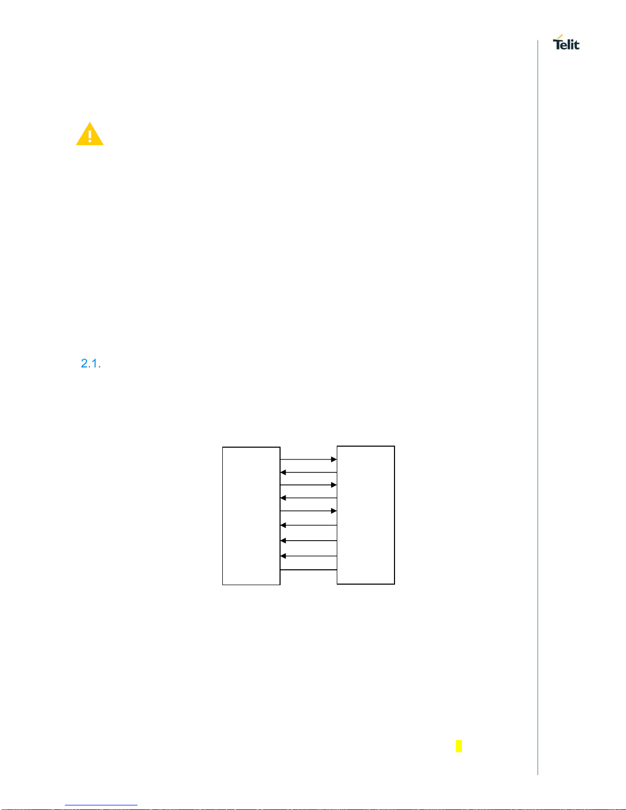
Serial Port Speed
Here is the V.24 serial interface standard provided by the Main Serial Port of the modules. To
have hardware information refer to document [1].
After power on, the module is ready to receive AT commands on its Main Serial Port. Its second
serial port, called Auxiliary, is used for factory test.
For example, type in the following AT command to verify if the DTE/DCE connection is working.
AT
OK
Use the following AT command to configure the Main Serial Port speed.
AT+IPR=<rate>
Use the Test command to get the Main Serial Port speed range expressed in bps; 0 = autobauding.
DTE (User Application)
DCE (Telit Module)
TxD
RxD
RTS
CTS
DTR
DSR
RI
DCD
GND
TxD
RxD
RTS
CTS
DTR
DSR
RI
DCD
GND
Page 13

1vv0301515 Rev.1 Page 13 of 59 2018-07-18
AT+IPR=?
+IPR:
0,75,150,300,600,1200,2400,4800,7200,9600,14400,19200,28800,38400,57600,115200,23040
0,460800,921600
OK
Use the Read command to get the current Main Serial Port speed.
AT+IPR?
+IPR: 115200 factory setting.
OK
Set up the Main Serial Port speed to 38400 bps.
AT+IPR=38400
OK
Before entering the following AT commands, set up the DTE serial port speed to 38400 bps.
Check the new current Main Serial Port speed.
AT+IPR?
+IPR: 38400 setting is not saved in NVM
OK
AT Error Report Format
Use Test command to know the available error report formats
AT+CMEE=?
+CMEE: (0-2)
OK
Disable the error report in numerical and verbose format.
AT+CMEE=0
OK
Enable the error report in numerical format.
AT+CMEE=1
OK
Enable the error report in verbose format.
AT+CMEE=2
OK
Module Identification
Use the following AT commands to verify the Software Versions and module identification.
Check the Software Versions.
AT+CGMR
34.00.000
OK
Page 14

1vv0301515 Rev.1 Page 14 of 59 2018-07-18
Check the module identification.
AT+CGMM
GL865-QUAD V4
OK
Page 15

1vv0301515 Rev.1 Page 15 of 59 2018-07-18
SIM Management
2.4.1. SIM Detection
Power off the module, extract the SIM (no PIN code active), and power on the module, then
enter the following command.
AT+ESIMS?
+ESIMS: 0 the SIM is not present
OK
The module is powered on, insert the SIM
AT+ESIMS?
+ESIMS: 0 the SIM is not detected
OK
Power off/on the module. The following URC is displayed:
+EUSIM: 1 the SIM is detected
Enter the following command.
AT+ESIMS?
+ESIMS: 1 the SIM is detected
OK
AT+CPIN?
+CPIN: READY
OK
AT+EPIN1?
+EPIN1: "READY"
OK
Page 16

1vv0301515 Rev.1 Page 16 of 59 2018-07-18
2.4.2. SIM Lock & Unlock
The following AT commands respectively:
locks/unlocks the SIM
AT+CLCK=<fac>,<mode>,<password>
checks if the SIM is locked, and allows the user to enter the PIN when the SIM is locked.
AT+CPIN=<pin>[,<newpin>]
Example 1
The SIM is inserted into the module. Power on the module, now check if the PIN must be
entered.
AT+CPIN?
+CPIN: SIM PIN the PIN code is needed, the SIM is locked
OK
Enter the PIN to unlock the SIM
AT+CPIN="XYXY"
OK
AT+CPIN?
+CPIN: READY the SIM is unlocked
OK
After 3 attempts failed, the PIN code is no longer requested and the SIM is
locked. Use SIM PUK to enter a new PIN code and unlock the SIM.
Example 2
Enter the following command, and power off/on the module to lock the SIM
AT+CLCK="SC",1,"XYXY"
OK
Check if the SIM has been locked.
AT+CPIN?
+CPIN: SIM PIN the SIM is locked
OK
AT+CPIN="XYXY"
OK
AT+CPIN?
+CPIN: READY
OK
Enter the following command to unlock the SIM
AT+CLCK="SC",0,"XYXY"
OK
Page 17

1vv0301515 Rev.1 Page 17 of 59 2018-07-18
Example 3
Extract the SIM and power off/on the module. Check if PIN code is needed, just to see the
command response when using different +CMEE setting.
+CMEE=0
AT+CPIN?
ERROR
+CMEE=1
AT+CPIN?
+CME ERROR: 10
+CMEE=2
AT+CPIN?
+CME ERROR: SIM not inserted
Page 18

1vv0301515 Rev.1 Page 18 of 59 2018-07-18
Network Information
2.5.1. Network Status
Use the following command to enable/disable network registration reports. The command syntax
is:
AT+CREG=[<mode>]
Use the Test command to get the range of the parameter value.
AT+CREG=?
+CREG: (0-2)
OK
Example
Check if the module is registered.
AT+CREG?
+CREG: 0,1 yes, it is registered.
OK
Now, disconnect the antenna from the module and enter again the command.
AT+CREG?
+CREG: 0,0 it is not registered.
OK
Connect again the antenna to the module, and select the Network Registration Report format:
Local Area Code and Cell Id.
AT+CREG=2
OK
AT+CREG?
+CREG: 2,1,"D5BD","0000520F",0
OK
2.5.2. Network Operator Identification
The following command executes an attempt to select and register the network operator. <mode>
parameter defines whether the operator selection is done automatically or it is established using
the operator identified by <oper> parameter.
AT+COPS=<mode>[,<format>,<oper>[,<Act>]]
Use the following command to query the module for Network Operators Identifications.
AT+COPS?
+COPS: 0,0,"22201"
OK
Test command returns, after a while, the list of the operators present on the air.
AT+COPS=?
Page 19

1vv0301515 Rev.1 Page 19 of 59 2018-07-18
+COPS:
(2,"22201","22201","22201",0),(1,"22210","22210","22210",0),(3,"22288","22288","22288",0),(1,"
29340","29340","29340",0),,(0-3),(0-2)
OK
Disconnect the antenna, wait a moment, and enter again the previous AT command.
AT+COPS=?
+COPS: ,(0-3),(0-2)
OK
2.5.3. Preferred Network Operator List
Use the following AT command to manage the Preferred Operator List stored on SIM. The
command syntax is:
AT+CPOL=[<index>][,<format>[,<oper> …
Check the supported number of operators in the SIM Preferred Operator List and the format:
AT+CPOL=?
+CPOL: (0-23), (0-2)
OK
Reading the entire list:
AT+CPOL?
+CPOL: 0,2,"23203",1,0,1
+CPOL: 1,2,"20610",1,0,1
+CPOL: 2,2,"28405",1,0,1
+CPOL: 3,2,"23002",1,0,1
+CPOL: 4,2,"23820",1,0,1
+CPOL: 5,2,"24491",1,0,1
………..
………..
+CPOL: 22,2,"24001",1,0,1
+CPOL: 23,2,"22801",1,0,1
OK
The meaning of the string "XXXYY" is: - XXX = Mobile Country Code
- YY = Mobile Network Code
Delete the entry in position 1, <index>=1
AT+CPOL=1
OK
Check if the entry is deleted.
AT+CPOL?
+CPOL: 0,2,"23203",1,0,1
+CPOL: 1,2,"",0,0,0 the entry is deleted
+CPOL: 2,2,"28405",1,0,1
……………
……………
OK
Page 20

1vv0301515 Rev.1 Page 20 of 59 2018-07-18
2.5.4. Signal Strength & Quality
Assume that the module is registered on a network. The following AT command returns the
received signal strength (<rssi>) and quality (<ber>), giving an indication about the radio link
reliability. The command syntax is:
AT+CSQ
Example 1
The antenna is not connected to the module or network coverage is not present at all.
AT+CSQ
+CSQ: 99,99
OK
The module is in idle state, the antenna is connected, and network coverage is present. Enter
again the previous AT command.
AT+CSQ
+CSQ: 18,99 18 = <rssi> = Received Signal Strength Indication
OK 99 = <ber> the module is in idle state, no Bit Error Rate
AT+CSQ=?
+CSQ: (0-31,99),(0-7,99)
OK
Example 2
Establish a voice call.
ATD 34XY92X4Y9;
OK voice channel is open
Get the received signal strength (<rssi>) and quality (<ber>) during a voice call
AT+CSQ
+CSQ: 12,0 12 = <rssi> = Received Signal Strength Indication
OK 0 = <ber> = Bit Error Rate in %
Close the voice channel
ATH
OK
Voice Call Establishment – Originate
Before setting up the voice call, it is assumed that the module is registered on a network and the
signal strength is enough to carry on a reliable radio link.
The following sub-chapters introduce AT commands regarding the audio features of the module.
2.6.1. Set Module in a Specific Mode
Use the following AT command to set up the module in a specific mode: data, fax class 1, fax
(manufacturer specific), fax class 2.
Page 21

1vv0301515 Rev.1 Page 21 of 59 2018-07-18
AT+FCLASS=?
(0, 1, 2, 2.0)
OK
Use the Read command to get the current setting.
AT+FCLASS?
0
OK
2.6.2. Dialing a Phone Number
Use the following AT command to establish a voice call. To perform the voice call you must use
the ";" character at the end of the command.
ATD<number>;
Examples
AT+FCLASS?
0 the current mode is data.
OK
Call the national number 040-4X92XYX.
ATD 0404X92XYX;
OK
Call the national number 040-4X92XYX in international format +39-040-4X92XYX.
ATD +390404X92XYX;
OK
If you do not use ";" character, the command returns NO CARRIER message.
ATD+390404X92XYX
NO CARRIER
2.6.3. Disconnect a Call
Use the following AT command to hang up the current voice call:
ATH
OK
Page 22

1vv0301515 Rev.1 Page 22 of 59 2018-07-18
2.6.4. Answering an Incoming Call
When an Incoming Call is recognized, the module sends to the DTE the RING message. Use
the following AT command to answer to the call.
RING
RING
ATA
OK
voice channel is on
2.6.5. Set Volume on Speaker
Use the following AT command to set up the output volume level:
AT+CLVL=<vol>
OK
Use the Test command to get the <vol> range
AT+CLVL=?
+CLVL: (0-6)
OK
Use the Read command to get the current value of <vol>.
AT+CLVL?
+CLVL: 3
OK
2.6.6. Set Microphone Mute
The following AT command mutes the microphone:
AT+CMUT=1
OK
Check the microphone setting:
AT+CMUT?
+CMUT: 1
OK
Page 23

1vv0301515 Rev.1 Page 23 of 59 2018-07-18
GSM Single Numbering Scheme
Most Network Operators use a primary phone number associated to the voice service and a
secondary phone number to data and fax. If the Operator employs a GSM Single Numbering
Scheme, the voice and data number is the same.
To select the bearer to be used when a mobile terminated Single Numbering Scheme call is
established, use the following AT command.
AT+CSNS=[<mode>]
Test command returns the supported bearers or teleservices
AT+CSNS=?
+CSNS: (0-7)
OK
Example 1
Read command returns the current bearer
AT+CSNS?
+CSNS: 0 voice (factory default)
OK
An Incoming Call is recognized:
RING
RING
ATA
voice channel is on
Example 2
Read command returns the current bearer
AT+CSNS=4 data
OK
An Incoming Call is recognized:
RING
RING
ATA
data channel is on
Page 24

1vv0301515 Rev.1 Page 24 of 59 2018-07-18
Call Management
2.8.1. Identifying the Call Type
The module can identify the call type before answering. To accomplish this feature, the module
provides different ring indications (URC) depending on the call type. It is up to the user to enable
the extended format reporting of incoming calls using the following AT command.
AT+CRC=[<mode>]
OK
Test command returns the supported values
AT+CRC=?
+CRC: (0,1)
OK
Example 1
Disable extended format reporting, and then assume that the module receives a call.
AT+CRC=0
OK
AT+CRC?
+CRC: 0 extended format reporting disabled.
OK
The module detects a call. Ring indications are displayed on DTE:
RING
RING
Example 2
Enable extended format reporting, and then assume the module receives a call.
AT+CRC=1
OK
AT+CRC?
+CRC: 1 extended format reporting enabled
OK
The module detects a call. Ring indications in extended format are displayed on DTE:
+CRING: VOICE
+CRING: VOICE
Page 25

1vv0301515 Rev.1 Page 25 of 59 2018-07-18
2.8.2. CLIP Calling Line Identification Presentation
The module can identify the caller number and give indication about it before the call is
answered. The Calling Line Indication is shown on DTE after each RING or +CRING indication.
The following AT command is used to enable/disable the Calling Line Identification Presentation.
AT+CLIP=[<n>]
Test command returns the supported values
AT+CLIP=?
+CLIP: (0-1)
OK
Example
Enable the extended call type format reporting.
AT+CRC=1
OK
Enable the caller number identification.
AT+CLIP=1
OK
AT+CLIP?
+CLIP: 1,1
OK
The module detects a call; ring indications and Calling Line Identification of the calling party are
displayed on DTE:
+CRING: VOICE
+CLIP: "+390404X92XYX",145,"",128,"",0
+CRING: VOICE
+CLIP: "+390404X92XYX",145,"",128,"",0
Page 26

1vv0301515 Rev.1 Page 26 of 59 2018-07-18
2.8.3. CLIR Calling Line Identification Restriction
The module can send the Calling Line Indication (CLI) to the other party through the Network when
an outgoing call is established. This indication can be restricted (CLIR) in various ways.
Use the following AT command to set the Calling Line Identification Restriction.
AT+CLIR=[<n>]
Test command returns the supported values
AT+CLIR=?
+CLIR: (0-2)
OK
Example 1
Check the current CLIR settings:
AT+CLIR?
+CLIR: 0,4
OK
<n> = 0 = CLIR module facility in accordance with CLIR Network Service
<m>= 4 = CLIR temporary mode presentation allowed (it is the facility status on the Network)
The <m> parameter reports the status of the service at Network level. If the CLIR service is not
provisioned by the Network, then it is not possible to use this service and changing the first
parameter <n> will not change the CLI presentation to the other party behavior of the Network.
Example 2
Check the current CLIR settings:
AT+CLIR?
+CLIR: 0,4
OK
Set CLIR facility active, CLI not sent.
AT+CLIR=1
OK
Check the current CLIR settings:
AT+CLIR?
+CLIR: 1,4
OK
Page 27

1vv0301515 Rev.1 Page 27 of 59 2018-07-18
2.8.4. Call Barring Control
The Call Barring Service enables the user to control the calls:
• Outgoing calls
• Outgoing international calls
• Outgoing international calls except those for its Country
• Incoming calls
• Incoming calls while roaming.
User can activate or cancel Call Barring using the AT commands hereafter described. The user
needs to enter a special access code (Call Barring Access Code) to modify Call Barring options.
Network Operator provides the Call Barring Code for every subscriber. Hereafter the Call Barring
Code is indicated as "network password".
The network handles the Call Barring Service: the module sends a network request and it may
take several seconds to have the response from the network. Furthermore, all the Call Barring
Service AT commands must be used when the module is registered on some network, otherwise
an error code is returned.
2.8.4.1. Lock/Unlock the Module
Use the following AT command to lock/unlock the module or Network facilities:
AT+CLCK=<fac>,<mode>[,<passwd>[,<class>]]
Test command returns the supported facilities:
AT+CLCK=?
+CLCK: ("PF","SC","AO","OI","OX","AI","IR","AB","AG","AC","FD","PN","PU","PP","PC")
OK
2.8.4.2. Call Barring Service Status
Use the following AT command to require the status of the selected network facility.
Only "SC", "AO", "OI", "OX", "AI", "IR" support query mode.
AT+CLCK=<fac>,2
Examples
Check the status of SIM facility:
AT+CLCK="SC",2
+CLCK: 0
OK
Check "IR" network facility status (Bar Incoming Calls status when roaming outside the home
country).
AT+CLCK="IR",2
+CLCK: 0,1
+CLCK: 0,2
Page 28

1vv0301515 Rev.1 Page 28 of 59 2018-07-18
+CLCK: 0,4
OK
"IR" network facility is unlocked (0): 1 = voice, 2 = data, 4 = fax.
Check "OI" network facility status (Bar Outgoing (originated) International Calls).
AT+CLCK="OI",2
+CLCK: 0,1
+CLCK: 0,2
+CLCK: 0,4
OK
"OI" network facility is unlocked (0): 1 = voice, 2 = data, 4 = fax.
Set the error report in verbose format, disconnect the antenna, and check "OI" network facility
status.
AT+CMEE=2
OK
AT+CLCK="OI",2
+CME ERROR: no network service
2.8.4.3. Bar/Unbar All Incoming Calls
Use the following AT command to change the status of the "AI" network facility (All Incoming Calls):
AT+CLCK="AI",<mode>,<passwd>
Examples
Lock and unlock "AI" network facility.
Check "AI" network facility status:
AT+CLCK="AI",2
+CLCK: 0,1
+CLCK: 0,2
+CLCK: 0,4
OK
"AI" network facility is unlocked (0): 1 = voice, 2 = data, 4 = fax.
Lock "AI" network facility. The network password is XXXX.
AT+CLCK="AI",1,"XXXX"
OK
Check "AI" facilities status:
AT+CLCK="AI",2
+CLCK: 1,1
+CLCK: 0,2
+CLCK: 0,4
OK
Page 29

1vv0301515 Rev.1 Page 29 of 59 2018-07-18
Unlock "AI" facilities:
AT+CLCK="AI",0,"XXXX"
OK
Check "AI" facilities status:
AT+CLCK=AI,2
+CLCK: 0,1
+CLCK: 0,2
+CLCK: 0,4
OK
"AI" network facility is unlocked (0): 1 = voice, 2 = data, 4 = fax.
2.8.4.4. Bar/Unbar Incoming Calls in International Roaming
Use the following AT command to change the status of the "IR" network facility (Incoming Calls
when Roaming outside the home country).
AT+CLCK="IR",<mode>,<passwd>
Examples
Lock and unlock "IR" network facility.
Check "IR" network facilities status:
AT+CLCK="IR",2
+CLCK: 0,1
+CLCK: 0,2
+CLCK: 0,4
OK
"IR" network facility is unlocked (0): 1 = voice, 2 = data, 4 = fax.
Lock "IR" network facility. The network password is XXXX
AT+CLCK="IR",1,"XXXX"
+CME ERROR: unknown setting not supported by the Network Operator
Change the Network Operator (change the SIM)
Lock "IR" network facility. The network password is YYYY
AT+CLCK="IR",1,"YYYY"
OK setting supported by the new Network Operator
Check "IR" facilities status:
AT+CLCK="IR",2
+CLCK: 1, 1
+CLCK: 0, 2
+CLCK: 1, 4
OK
"IR" network facility is locked (1): 1 = voice, 2 = data, 4 = fax.
Page 30

1vv0301515 Rev.1 Page 30 of 59 2018-07-18
2.8.4.5. Bar/Unbar All Outgoing Calls
Use the following AT command to change the status of the "AO" network facility (All Outgoing
Calls).
AT+CLCK="AO",<mode>,<passwd>
Examples
Check "AO" network facility status:
AT+CLCK="AO",2
+CLCK: 0,1
+CLCK: 0,2
+CLCK: 0,4
OK
"AO" network facility is unlocked (0): 1 = voice, 2 = data, 4 = fax.
Lock "AO" network facility. The network password provided by Network Operator is XXXX.
AT+CLCK="AO",1,"XXXX"
OK
Check "AO" network facility status:
AT+CLCK="AO",2
+CLCK: 1,1
+CLCK: 0,2
+CLCK: 0,4
OK
Unlock "AO" network facility:
AT+CLCK="AO",0,"XXXX"
OK
Checking "AO" network facility status:
AT+CLCK="AO",2
+CLCK: 0,1
+CLCK: 0,2
+CLCK: 0,4
OK
"AO" network facility is unlocked (0): 1 = voice, 2 = data, 4 = fax.
Page 31

1vv0301515 Rev.1 Page 31 of 59 2018-07-18
2.8.4.6. Bar/Unbar All Outgoing International Calls
Use the following AT command to change the status of the "OI" network facility (Outgoing
International Calls).
AT+CLCK="OI",<mode>,<passwd>
Examples
Lock and unlock "OI" network facility.
Checking "OI" network facility status:
AT+CLCK="OI",2
+CLCK: 0,1
+CLCK: 0,2
+CLCK: 0,4
OK
"OI" network facility is unlocked (0): 1 = voice, 2 = data, 4 = fax.
Lock "OI" network facility. The network password is XXXX.
AT+CLCK="OI",1,"XXXX"
OK
Check "OI" network facility status:
AT+CLCK="OI",2
+CLCK: 1,1
+CLCK: 0,2
+CLCK: 0,4
OK
Unlock "OI" network facility:
AT+CLCK="OI",0,"XXXX"
OK
Check "OI" network facility status:
AT+CLCK="OI",2
+CLCK: 0,1
+CLCK: 0,2
+CLCK: 0,4
OK
"OI" network facility is unlocked (0): 1 = voice, 2 = data, 4 = fax.
Page 32

1vv0301515 Rev.1 Page 32 of 59 2018-07-18
2.8.4.7. Bar/Unbar All Outgoing Internat. Calls except to Home Country
Use the following AT command to change the status of the "OX" network facility (Outgoing
International Calls except to Home Country).
AT+CLCK="OX",<mode>,<passwd>
Examples
Lock and unlock "OX" network facility.
Check "OX" network facility status:
AT+CLCK="OX",2
+CLCK: 0,1
+CLCK: 0,2
+CLCK: 0,4
OK
"OX" network facility is unlocked (0): 1 = voice, 2 = data, 4 = fax.
Lock "OX" network facility. The network password is XXXX.
AT+CLCK="OX",1,"XXXX"
+CME ERROR: unknown setting is not supported by the network
AT+CLCK="OX",0,"0000"
+CME ERROR: unknown setting is not supported by the network
Check "OX" network facility status:
AT+CLCK="OX",2
+CLCK: 0,1
+CLCK: 0,2
+CLCK: 0,4
OK
"OX" network facility is unlocked (0): 1 = voice, 2 = data, 4 = fax.
Page 33

1vv0301515 Rev.1 Page 33 of 59 2018-07-18
2.8.4.8. Unbar All Calls
Use the following AT command to change the status of the "AB" network facility (All Barring
services)
AT+CLCK="AB",<mode>,<passwd>
Examples
Unlock "AB" network facility. The network password provided by Network Operator is XXXX.
AT+CLCK="AB",0,"XXXX"
OK
Check "IR" network facility status:
AT+CLCK="IR",2
+CLCK: 0,1
+CLCK: 0,2
+CLCK: 0,4
OK
"IR" network facility is unlocked (0): 1 = voice, 2 = data, 4 = fax.
Check "OI" network facility status:
AT+CLCK="OI",2
+CLCK: 0,1
+CLCK: 0,2
+CLCK: 0,4
OK
"OI" network facility is unlocked (0): 1 = voice, 2 = data, 4 = fax.
Check "AI" network facility status:
AT+CLCK="AI",2
+CLCK: 0,1
+CLCK: 0,2
+CLCK: 0,4
OK
"AI" network facility is unlocked (0): 1 = voice, 2 = data, 4 = fax.
Page 34

1vv0301515 Rev.1 Page 34 of 59 2018-07-18
DTMF Tones
Test command returns the supported DTMF.
AT+VTS=?
+VTS: 0,1,2,3,4,5,6,7,8,9,A,B,C,D,#,*
OK
Example
An Incoming Call is recognized, the module sends to the DTE the RING message. Use the
following AT command to answer to the call.
RING
RING
ATA
OK voice channel is on
AT+VTS=9 send single DTMF
AT+VTS=6;+VTS=2;+VTS=8;+VTS=2 send multiple DTMF
…..
…..
Page 35

1vv0301515 Rev.1 Page 35 of 59 2018-07-18
SMS Management
The SMS Service stores, sends, receives, and deletes SMSs, which are short text messages up
to 160 characters long. Before using the SMS messages, you must configure the Short Message
Service.
2.10.1. Select SMS Format Type
The module supports two SMS formats:
• PDU mode
• Text mode
The module uses the PDU format to send a message on the air. The PDU mode enables the user
to edit the message in PDU format. If the user is familiar with PDU encoding, he can operate with
PDU by selecting that mode and use the appropriate commands.
The present document uses the Text mode to explain how to operate with SMS. Here is the AT
command to select the mode.
AT+CMGF=[<mode>]
Examples
Test command returns the supported range of values:
AT+CMGF=?
+CMGF: (0,1)
OK
Read command returns the current setting
AT+CMGF?
+CMGF: 0 PDU mode
OK
Set up Text Mode for the SMS:
AT+CMGF=1
OK
This setting is active until the module is turned OFF.
Page 36

1vv0301515 Rev.1 Page 36 of 59 2018-07-18
2.10.1.1. Set Text Mode Parameters
When SMS format is Text mode, the SMS parameters that usually reside on the header of the
PDU must be set apart with the +CSMP command.
AT+CSMP=[<fo>[,<vp>[,<pid>[,<dcs>]]]]
Read command returns the current setting
AT+CSMP?
+CSMP: 0, 167, 0, 0
OK
Example 1
Set the SMS parameters as follow:
• <fo> expressed in binary format, see table below. The binary number expressed in
decimal format is 17.
0 0 0
1 0 0 0 1
Module is not requesting a
status report
Always 0
Replay Path not
requested
Validity period field
present in relative format
Always 0
SMS-SUBMIT
• <vp> validity period (in relative format) = 24 hours is coded into 167 decimal format.
• <pid> protocol identifier.
• <dcs> data coding scheme, default value 0.
AT+CSMP= 17,167,0,0
OK
NOTE: the setting is automatically saved.
2.10.1.2. Character Sets
Use the following AT command to select the character set:
AT+CSCS=[<chset>]
Test command returns the supported character sets:
AT+CSCS=?
+CSCS: ("IRA", "GSM", "HEX", "PCCP437", "8859-1", "UCS2", "UCS2_0X81")
OK
Read command returns the current character set:
AT+CSCS?
+CSCS: "IRA"
OK
2.10.1.2.1. IRA Character Set
The IRA character set is used in Text mode. IRA set defines each character as a 7-bit value: from
0x00 to 0x7F. The table below lists all the supported characters and their hexadecimal code.
Page 37

1vv0301515 Rev.1 Page 37 of 59 2018-07-18
Most Significant Nibble
0x
1x
2x
3x
4x
5x
6x
7x
Least Significant Nibble
x0
SP
1
0 @ P p
x1
! 1 A Q a q x2
" 2 B R b r x3
# 3 C S c s x4
$ 4 D T d t x5
% 5 E U e u x6
& 6 F V f
v
x7
‘ 7 G W g
w
x8
( 8 H X h x x9
) 9 I Y i
y
xA
LF
2
* : J Z j
z
xB
+ ; K k
xC
, < L l
xD
CR
3
- = M m
xE
. > N n xF
/ ? O £ o
1
– SP stands for space character
2
– LF stands for Line Feed character
3
– CR stands for Carriage Return character
The following examples show how to use the IRA table:
• Get the IRA code of the character ‘&’: the most significant nibble is 2, the least significant
nibble is 6, so the IRA code for the ‘&’ character is the hexadecimal value: 0x26.
• Translate IRA code 0x6B into the corresponding character: the most significant nibble is
6, the least significant nibble is B, the cell at the crossing of column 6 and row B holds
the character: "k".
2.10.1.2.2. UCS2 Character Set
The UCS2 Character Set is used in Text mode.
• Phone number 329 05 69 6... converted into "UCS2" format: 3=0033, 2=0032, 9=0039,
0=0030, 5=0035, 6=0036, 9=0039, 6=0036 ...
• Text HELLO converted into UCS2 format: H=0048, E=0045, L=004C, O=004F
2.10.2. Read/Write SMSC Number
The module sends the SMS message to the SMSC Center, where the message is dispatched
towards its destination or is kept until the delivery is possible. To ensure the correct operation of
this service, the number of the SMSC Center must be configured on the module in accordance
with the network operator used.
To know the SMSC number stored on the module, use the following AT command.
AT+CSCA?
+CSCA: "+39X20XX58XX0",145
OK
SMSC number is compliant with the international numbering scheme.
Page 38

1vv0301515 Rev.1 Page 38 of 59 2018-07-18
Use the following AT command to store a new SMSC number. The old number is overwritten.
AT+CSCA=<number>,<type>
Set up the desired SMSC number in international format:
AT+CSCA="+39X20XX58XX0",145
OK
This setting remains stored in the SIM card until it is changed or deleted, so this operation may
be done only once if the SIM Card is not changed.
Enter the command with no SMSC number:
AT+CSCA=,145
OK
Check the stored SMSC number:
AT+CSCA?
+CSCA: "+",145
OK
2.10.3. SMS Storage
Module can provide the following SMS storage, grouped into three groups <mem1>, <mem2>,
and <mem3>. The following test command returns the supported SMS storage groups:
AT+CPMS=?
+CPMS: ("SM", "ME", "SM_P", "ME_P", "MT"), ("SM", "ME", "SM_P", "ME_P", "MT"), ("SM",
"ME", "SM_P", "ME_P", "MT")
OK
<mem1>: memory from which SMS messages are read and deleted
• "SM" SIM Card Memory
• "ME" Mobile Equipment Memory
• "SM_P" Manufacturer Specific
• "ME_P" Manufacturer Specific
• "MT" Storages associated with ME
<mem2>: memory to which writing and sending operations are made
• "SM" SIM Card Memory
• "ME" Mobile Equipment Memory
• "SM_P" Manufacturer Specific
• "ME_P" Manufacturer Specific
• "MT" Storages associated with ME
<mem3>: memory to which the received SMS are preferred to be stored
• "SM" SIM Card Memory
• "ME" Mobile Equipment Memory
• "SM_P" Manufacturer Specific
• "ME_P" Manufacturer Specific
• "MT" Storages associated with ME
Page 39

1vv0301515 Rev.1 Page 39 of 59 2018-07-18
Select memory storage "SM":
AT+CPMS="SM"
+CPMS: 15, 30, 15, 30, 15, 30
OK
AT+CPMS?
+CPMS: "SM", 15, 30, "SM_P", 15, 30, "SM_P", 15, 30
OK
Select memory storage "ME":
AT+CPMS="ME"
+CPMS: 0, 50, 15, 30, 15, 30
OK
AT+CPMS?
+CPMS: "ME", 0, 50, "SM_P", 15, 30, "SM_P", 15, 30
OK
Select memory storage "SM_P":
AT+CPMS="SM_P"
+CPMS: 15, 30, 15, 30, 15, 30
OK
AT+CPMS?
+CPMS: "SM_P", 15, 30, "SM_P", 15, 30, "SM_P", 15, 30
OK
AT+CPMS="ME_P"
+CPMS: 0, 50, 15, 30, 15, 30
OK
AT+CPMS?
+CPMS: "ME_P", 0, 50, "SM_P", 15, 30, "SM_P", 15, 30
OK
AT+CPMS="MT"
+CPMS: 15, 80, 15, 30, 15, 30
OK
AT+CPMS?
+CPMS: "MT", 15, 80, "SM_P", 15, 30, "SM_P", 15, 30
OK
Page 40

1vv0301515 Rev.1 Page 40 of 59 2018-07-18
2.10.4. SMS Receiving/Reading & Sending
Use the following AT command to read a SMS received.
AT+CMGR
Example
Check the current character set.
AT+CSCS?
+CSCS: "IRA"
OK
Check the SMS format
AT+CMGF?
+CMGF: 1 Text Mode
OK
Check header parameters of SMS
AT+CSMP?
+CSMP: 0, 168, 0, 240
OK
Select memory storage "SM":
AT+CPMS="SM"
+CPMS: 15, 30, 15, 30, 15, 30
OK
Check the number of SMS stored: 15
AT+CPMS?
+CPMS: "SM", 15, 30, "SM_P", 15, 30, "SM_P", 15, 30
OK
When the module receives a new SMS, an Unsolicited Result Code is generated. This indication
may be sent to the DTE, buffered if the DTE is busy (for example, during a data call), or
discarded. To set the desired behavior, use the following command:
Select how the module notifies to the DTE the new SMS receiving from the network.
AT+CNMI=1,1,0,0,0
OK
Now, a remote device sends a SMS, the DTE displays the following URC:
+CMTI: "SM", 16 16 is the SMS index the "SM" memory
Check the number of SMS stored: 16
AT+CPMS?
+CPMS: "SM", 16, 30, "SM_P", 16, 30, "SM_P", 16, 30
OK
Read the SMS pointed by index=16. The SMS body is in yellow.
AT+CMGR=16
+CMGR: "REC UNREAD","393477928479","","2018/03/07 14:36:25+04"
SMS #1
OK
Page 41

1vv0301515 Rev.1 Page 41 of 59 2018-07-18
Use the following AT command to send a SMS.
AT+CMGS
Example
Send a SMS to the remote device, and do not store it.
Select Text Mode
AT+CMGF=1
OK
Select how the new received message event is notified by the DCE to the DTE.
AT+CNMI=1,1,0,0,0
OK
Send a SMS to the remote device. The SMS body is yellow.
AT+CMGS="+39347XY284XY"
> SMS #2 close the message with Ctrl Z or ESC to abort
+CMGS: 113
OK
Page 42

1vv0301515 Rev.1 Page 42 of 59 2018-07-18
2.10.5. Store and Send a SMS
Use the following AT command to store a SMS.
AT+CMGW=<da>
Use the following AT command to send the SMS stored.
AT+CMSS=<index>
Example
Stores a new SMS in the "SM" storage, send it to the remote device, and read the message in
the receiving storage.
AT+CMGF=1 Select Text Mode
OK
AT+CSMP=17,168,0,240 Assume to send a SMS of Class 0
OK
Select how the new received message event is notified by the DCE to the DTE
AT+CNMI=1,1,0,0,0
OK
Store into "SM" the SMS message to be sent to the module itself.
AT+CMGW="+39347XY284XY "
> SMS #3 close with Ctrl Z or ESC to abort
+CMGW: 17
OK
Read the just stored SMS identified by index=17
AT+CMGR=17
+CMGR: "STO SENT","39347XY284XY",""
SMS #3
OK
Send the stored SMS #3 using the storage position returned by the previous command.
AT+CMSS=17
+CMSS: 114
OK
AT+CPMS?
+CPMS: "SM", 17, 30, "SM_P", 17, 30, "SM_P", 17, 30
OK
Page 43

1vv0301515 Rev.1 Page 43 of 59 2018-07-18
2.10.6. Delete a SMS
Use the following AT command to delete a SMS stored on the "SM" storage type.
AT+CMGD=<index>
Example
Deleting an SMS stored in "SM" storage type:
AT+CPMS="SM" Select memory storage
+CPMS: 17, 30, 17, 30, 17, 30
OK
Delete SMS in memory position 17.
AT+CMGD=17
OK
AT+CPMS="SM"
+CPMS: 16, 30, 16, 30, 16, 30
OK
Delete all SMS. Disregard the first parameter of the +CMGD.
AT+CMGD=1,4
OK
AT+CPMS="SM"
+CPMS: 0, 30, 0, 30, 0, 30
OK
2.10.7. SMS Status
SMSs can be gathered into 5 different groups depending on their status:
• REC UNREAD: received messages not read
• REC READ: received messages read
• STO UNSENT: written messages not sent
• STO SENT: written messages sent
• ALL: all types of messages
Use the following AT command to query the SMS status:
AT+CMGL=<stat>
Example 1
Check if Text Mode is active
AT+CMGF?
+CMGF: 1 Text Mode is active
OK
Check the supported SMS status
AT+CMGL=?
+CMGL: ("REC UNREAD","REC READ","STO UNSENT","STO SENT","ALL")
OK
Page 44

1vv0301515 Rev.1 Page 44 of 59 2018-07-18
Read command returns the current SMS storage groups
AT+CPMS?
+CPMS: "SM", 2, 30, "SM_P", 2, 30, "SM_P", 2, 30
OK
List all the SMSs stored on "SM" storage with their Status.
AT+CMGL="ALL"
+CMGL: 1,"REC READ", •••• SMS body ••••
+CMGL: 2,"REC READ", •••• SMS body ••••
OK
List the SMSs stored on "SM" storage with their Status=STO SENT
AT+CMGL="STO SENT"
OK
Example 2
Check if Text Mode is active.
AT+CMGF?
+CMGF: 1
OK
Check the supported SMS status.
AT+CMGL=?
+CMGL: ("REC UNREAD","REC READ","STO UNSENT","STO SENT","ALL")
OK
Select "ME" storage type.
AT+CPMS="ME"
+CPMS: 0, 50, 2, 30, 2, 30
OK
List SMSs stored in the "ME" storage type.
AT+CMGL="ALL"
OK
AT+CMGL="REC UNREAD"
OK
Page 45

1vv0301515 Rev.1 Page 45 of 59 2018-07-18
Phonebooks
The user can access the different Phonebook types, stored on the SIM card or on the NVM
memory, by means of the dedicated AT commands.
2.11.1. Phonebook Storage
The choice of the Phonebook Storage must be the first Phonebook operation. Once storage is
selected, it is no longer needed to select it again until the desired storage remains the same, and
the module is not turned off.
Use the following command to select the phonebook memory storage identified by <storage>
parameter. To have more information on the command refer to document. The command syntax
is:
AT+CPBS=<storage>
Test command returns the <storage> range provided by the module.
AT+CPBS=?
Example
Read the supported range of Phonebook Storages. The <storage> range depends on the SIM,
that must be inserted.
AT+CPBS=?
+CPBS: ("ME","SM","LD","MC","RC","FD","DC","ON")
OK
Read the current phonebook storage
AT+CPBS?
+CPBS: "SM", 1, 50
OK
Select "FD" phonebook storage.
AT+CPBS="FD"
OK
AT+CPBS?
+CPBS: "FD", 0, 13
OK
Select "MC" Phonebook Storage
AT+CPBS="MC"
OK
AT+CPBS?
+CPBS: "MC", 0, 10
OK
Page 46

1vv0301515 Rev.1 Page 46 of 59 2018-07-18
2.11.2. Search Phonebook Entries
Use the following AT command to search a Phonebook entry.
AT+CPBF=<findtext>
Examples
AT+CPBS="SM"
OK
AT+CPBS?
+CPBS: "SM", 4, 50
OK
Look for entries having name starting with "New" on the selected storage:
AT+CPBF="New"
+CPBF: 2, "1234567890", 129, "New1Record"
+CPBF: 4, "1234567890", 129, "New3Record"
+CPBF: 5, "1234567890", 129, "NEW4Record"
OK
2.11.3. Read Phonebook Entries
Use the following AT command to read a Phonebook entry:
AT+CPBR=<index1>[,<index2>]
Select "SM" storage:
AT+CPBS="SM"
OK
AT+CPBS?
+CPBS: "SM", 3, 50
OK
Look for the entry at the position index = 1:
AT+CPBR=1
+CPBR: 1, "1234567890", 129, "NewRecord"
OK
AT+CPBR=2
+CPBR: 2, "1234567890", 129, "New1Record"
OK
AT+CPBR=3
+CPBR: 3, "1234567890", 129, "New2Record"
OK
Look for the entries from position 7 up to position 9:
AT+CPBR=1,3
+CPBR: 1, "1234567890", 129, "NewRecord"
+CPBR: 2, "1234567890", 129, "New1Record"
+CPBR: 3, "1234567890", 129, "New2Record"
OK.
Page 47

1vv0301515 Rev.1 Page 47 of 59 2018-07-18
2.11.4. Write Phonebook Entry
Use the following AT command to write a Phonebook entry:
AT+CPBW=[<index>][,<number>[,<type>[,<text>]]]
Examples
Select the "SM" phonebook:
AT+CPBS="SM"
OK
Read the current phonebook storage
AT+CPBS?
+CPBS: "SM", 3, 50
OK
Write a new record on the first free position of the selected "SM" phonebook:
AT+CPBW=,"1234567890",129,"New3Record"
OK
Read the current phonebook storage
AT+CPBS?
+CPBS: "SM", 4, 50
OK
Check where the New record has been written (case sensitive):
AT+CPBF="New"
+CPBF: 2, "1234567890", 129, "New1Record"
+CPBF: 3, "1234567890", 129, "New2Record"
+CPBF: 4, "1234567890", 129, "New3Record"
+CPBF: 1, "1234567890", 129, "NewRecord"
OK
Write another record
AT+CPBW=,"1234567890",129,"NEW4Record"
OK
Check where the NEW record has been written (case sensitive):
AT+CPBF="NEW"
+CPBF: 5, "1234567890", 129, "NEW4Record"
OK
Page 48

1vv0301515 Rev.1 Page 48 of 59 2018-07-18
2.11.5. Delete Phonebook Entry
Use the following AT command with only <index> parameter to delete a Phonebook entry:
AT+CPBW=<index>
Examples
Select the "SM" phonebook:
AT+CPBS="SM"
OK
Delete entry in position 3 on the "SM" phonebook:
AT+CPBW= 3
OK
AT+CPBF="New"
+CPBF: 2, "1234567890", 129, "New1Record"
+CPBF: 4, "1234567890", 129, "New3Record"
+CPBF: 5, "1234567890", 129, "NEW4Record"
OK
2.11.6. Dial Phonebook Entry
To dial a phone number stored in the Phonebook, the user must get the desired phone number
index position using the +CPBF command. Once the <index> number is known, the user can
establish the call.
ATD><n>[;]
Wait for command response in accordance with the call type entered.
Examples
Establish a Voice call, on HS audio path, to "Fabio" whose number is stored on the SIM
Phonebook:
Select the "SM" as active storage.
AT+CPBS="SM"
OK
Find the index number where "Fabio" is recorded.
AT+CPBF="NAME"
+CPBF: 3,"+390404X9YYYY",145,"NAME"
OK
Set the volume.
AT+CLVL=6
OK
Check the mute setting.
AT+CMUT?
+CMUT: 0 mute OFF
OK
Page 49

1vv0301515 Rev.1 Page 49 of 59 2018-07-18
Establish the voice call using the index.
ATD>3
OK
Page 50

1vv0301515 Rev.1 Page 50 of 59 2018-07-18
Clock and Alarm Functions
The module provides Real Time Clock and Alarm features. The next chapters describe examples
showing AT commands used to:
• set up the right time
• check the actual time
• set up an alarm time
• delete an alarm time
2.12.1. Clock
2.12.1.1. Set Module Clock
Use the following AT command to update the module clock.
AT+CCLK=<time>
<time> is a string type value. Its format is "yy/MM/dd,hh:mm:ss"
Set up the clock to 12 March 2018 at 10h 27m 30s
AT+CCLK="18/03/12,10:27:30"
OK
The time is successfully set. The updated time starts immediately after the time setting command.
2.12.1.2. Read the Current Date and Time
Use the following AT command to display the current module time.
AT+CCLK?
Read the current time:
AT+CCLK?
+CCLK: "18/03/12,10:29:05" Current date/time is: 12 March 2018 10h 29m 05s
OK
2.12.2. Alarm
2.12.2.1. Set Alarm
Use the following AT command to set up the alarm configuration:
AT+CALA=<time>[,<n>[,<type>[,<text>[<recur>]]]]
Example
Read the current time.
AT+CCLK?
+CCLK: "18/03/12,10:33:47"
OK
Set up the alarm configuration: <n>=0 is the alarm index, <type> and <text> are dummy values.
AT+CALA="18/03/12,10:44:30",0,1,"Dummy"
OK
AT+CCLK?
Page 51

1vv0301515 Rev.1 Page 51 of 59 2018-07-18
+CCLK: "18/03/12,10:43:40"
OK
AT+CCLK?
+CCLK: "18/03/12,10:44:08"
OK
AT+CCLK?
+CCLK: "18/03/12,10:44:22"
OK
The alarm time is reached, the module displays on the DTE the following URC.
+CALV: 0 alarm index is 0.
2.12.2.2. Delete Alarm
Example
Follow these commands to set up and delete the alarm using its index. Read the current time.
AT+CCLK?
+CCLK: "18/03/12,10:44:22"
OK
Set up the alarm configuration, the alarm index is 0.
AT+CALA="18/03/12,10:55:30",0,1,"Dummy"
OK
Read the current time
AT+CCLK?
+CCLK: "18/03/12,10:45:22"
OK
Read the current time
AT+CCLK?
+CCLK: "18/03/12,10:48:30"
OK
The alarm time is not reached. Delete the alarm configuration using the alarm index.
AT+CALD=0
OK
Read the current time
AT+CCLK?
+CCLK: "18/03/12,10:58:20"
OK
The alarm time is over, the unsolicited +CALV: 0 message is not appeared on the DTE in
accordance with AT+CALD=0 command.
Page 52

1vv0301515 Rev.1 Page 52 of 59 2018-07-18
Check the supported alarm indexes
AT+CALD=?
+CALD: (0) is supported only alarm index = 0
OK
2.12.2.3. Recurrent Alarm
Follow these commands to set up the recurrent alarm configuration.
Read the current time
AT+CCLK?
+CCLK: "18/03/12,11:28:20"
OK
Set up the alarm configuration, the alarm index <n>=0. <recur>=0 sets a recurrent alarm for all
days in the week.
AT+CALA="18/03/12,11:55:30",0,1,"Dummy",0
OK
Read the current time
AT+CCLK?
+CCLK: "18/03/12,11:45:20" the alarm time is still not reached
OK
The Alarm time is reached, the module displays on the DTE the following URC.
+CALV: 0 alarm index is 0.
Set up the new day to simulate the passing of time
AT+CCLK="18/03/13,11:42:00+00
OK
Read the current time
AT+CCLK?
+CCLK: "18/03/13,11:44:25" the alarm time is still not reached
OK
The alarm time is reached, the module displays on the DTE the following URC.
+CALV: 0 alarm index is 0.
Page 53

1vv0301515 Rev.1 Page 53 of 59 2018-07-18
GPIO Pins Configuration
The module provides 8 GPIO pins, which can be configured in input or output direction.
AT#GPIO=[<pin>,<mode>[,<dir>]]
User applications, through GPIO AT commands, can control external user equipment connected
to GPIO pins. Simple or no circuitries are needed to perform the required hardware interface.
The GPIO setting is not saved on power off. At power on, repeat the GPIO
setting. For detailed GPIO pins descriptions refer to document [1].
2.13.1. Set GPIO Pin as Output
Use the following AT command to set a GPIO as output with Low or High-status value.
AT#GPIO=<pin>,<mode>,1
Set GPIO1 pin as Output with Low status:
AT#GPIO=1,0,1
OK GPIO1 pin is set in output; its status is Low
Set GPIO1 pin as Output with High status:
AT#GPIO=1,1,1
OK GPIO1 pin is set in output; its status is High
2.13.2. Set GPIO Pin as Input
Use the following AT command to set a GPIO as input. A dummy value must be specified for pin
status value.
AT#GPIO=<pin>,<dummy_value>,0
Example
Set GPIO9 pin as Input:
AT#GPIO=3,0,0
OK GPIO3 pin is set in input
Page 54

1vv0301515 Rev.1 Page 54 of 59 2018-07-18
2.13.3. Get GPIO Pin Status
Use the following AT command to check the pin status.
AT#GPIO=<pin>,2
Example
Set GPIO1 pin as output with Low status.
AT#GPIO=1,0,1
OK
Set GPIO2 pin as input.
AT#GPIO=2,0,0
OK
Now, physically connect GPIO1 with GPIO2, and check the GPIO2 status.
The command returns: <dir> and <status>
AT#GPIO=2,2
#GPIO: 0,0 GPIO2 pin status is Low, as commanded by GPIO1.
Set GPIO1 pin as output with High status.
AT#GPIO=1,1,1
OK
Check the GPIO2 status. The command returns: <dir> and <status>
AT#GPIO=2,2
#GPIO: 0,1 GPIO2 pin status is High, as commanded by GPIO2.
Check the GPIO1 status.
AT#GPIO=1,2
#GPIO: 1,1
Read Analog/Digital Converter Input
Use the following AT command to read the ADC input voltage.
AT#ADC
#ADC: 1050 voltage value expressed in mV
OK
Page 55

1vv0301515 Rev.1 Page 55 of 59 2018-07-18
3. DATA CONNECTION
GPRS Activation
Power on the module, the SIM is inserted.
+EUSIM: 1 SIM is detected
Check if the module is registered.
AT+CREG?
+CREG: 0,1 yes, it is registered.
OK
Check on which Network Operator the module is registered.
AT+COPS?
+COPS: 0,0,"22201"
OK
Check if the module is GPRS attached
AT+CGATT?
+CGATT: 1 GPRS attached
OK
Set a PDP context, <cid>=1
AT+CGDCONT= 1,"IP","APN"
OK
NOTE: setting is saved.
Check how many PDP contexts are defined.
AT+CGDCONT?
+CGDCONT: 1,"IP","APN","0.0.0.0",0,0
OK
Activate PDP context identified by <cid>=1.
AT+CGACT=1,1
OK
Get the IP address assigned to the module by the network
AT+CGPADDR=1
+CGPADDR: 1, "2.192.14.28"
OK
Deactivated the PDP context identified by <cid>=1
AT+CGACT=0,1
OK
No address is assigned.
AT+CGPADDR=1
+CGPADDR: 1, ""
OK
Page 56

1vv0301515 Rev.1 Page 56 of 59 2018-07-18
Connection to an Echo TCP Server
Power on the module, the SIM is inserted.
+EUSIM: 1 SIM is detected
Data account id, total 3 accounts.
AT+EGDCONT=?
+EGDCONT: (0-2),"IP",,,,
OK
Define TCP/IP data account.
AT+EGDCONT=0,"IP","APN"
OK
AT+EGDCONT?
+EGDCONT: 0,"IP","APN" setting is not saved in NVM
OK
Activate PDP. Data account id = 0
AT+ETCPIP=1,0
OK
Create a socket and return socket id. Connection to an echo TCP server.
1: create e socket and returns its id
0: data account id
0: TCP
"…": destination IP address
"…": destination port
AT+ETL=1,0,0,"XXX.YY.YYY.XXX",20510
+ETL: 1 socket id=1
OK
Using the socket id=1, send data
AT+EIPSEND=1,"0123456789"
+EIPSEND: 1, 5
OK
+ESOCK: 1 READY RECV URC that notifies the data reception
Receive data
AT+EIPRECV=1
+EIPRECV: 1,"0123456789"
OK
Close socket id=1
AT+ETL=0,1
OK
Page 57

1vv0301515 Rev.1 Page 57 of 59 2018-07-18
4. GLOSSARY AND ACRONYMS
Description
APN
Access Point Name
CSD
Circuit Switched Data
CTS
Clear To Send
DCE
Data Circuit-Terminating Equipment
DTE
Data Terminal Equipment
DTMF
Dual Tone Multiple Frequency
DTR
Data Terminal Ready
GPIO
General Purpose Input/Output
IRA
International Reference Alphabet
ME
Mobile Equipment
MSISDN
Mobile Station International Subscriber Directory Number
NVM
Non-Volatile Memory
PDN
Public Data Network
PDP
Packet Data Protocol
PDU
Protocol Data Unit
PIN
Personal Identification Number
QoS
Quality of Service
SIM
Subscriber Identification Module
SMS
Short Message Service
SMSC
Short Message Service Center
TCP/IP
Transmission Control Protocol / Internet Protocol
UE
User Equipment
URC
Unsolicited Result Code
Page 58

1vv0301515 Rev.1 Page 58 of 59 2018-07-18
5. DOCUMENT HISTORY
Revision
Date
Changes
0
2018-03-15
First issue
1
2018-07-18
In chapter 2 added a note about sleep mode and the related
AT command.
Page 59

Mod. 0815
 Loading...