

Telit Wireless Solutions EVK Series, EVK4-HE910-GL Series, EVK4-LE910-NA1 Series, EVK4-LE910-EU1 Series User Manual
Page 1

Mod. 0805 2016-08 Rev.5
TELIT EVK 3G/4G IoT Development Kit
HW User Guide
1VV0301381 Rev. 1 – 2017/05/25
Page 2

Telit EVK4 HW User Guide\
SPECIFICATIONS ARE SUBJECT TO CHANGE WITHOUT NOTICE
NOTICE
While reasonable efforts have been made to assure the accuracy of this document, Telit
assumes no liability resulting from any inaccuracies or omissions in this document, or from
use of the information obtained herein. The information in this document has been carefully
checked and is believed to be reliable. However, no responsibility is assumed for
inaccuracies or omissions. Telit reserves the right to make changes to any products
described herein and reserves the right to revise this document and to make changes from
time to time in content hereof with no obligation to notify any person of revisions or changes.
Telit does not assume any liability arising out of the application or use of any product,
software, or circuit described herein; neither does it convey license under its patent rights
or the rights of others.
It is possible that this publication may contain references to, or information about Telit
products (machines and programs), programming, or services that are not announced in
your country. Such references or information must not be construed to mean that Telit
intends to announce such Telit products, programming, or services in your country.
COPYRIGHTS
This instruction manual and the Telit products described in this instruction manual may be,
include or describe copyrighted Telit material, such as computer programs stored in
semiconductor memories or other media. Laws in the Italy and other countries preserve for
Telit and its licensors certain exclusive rights for copyrighted material, including the
exclusive right to copy, reproduce in any form, distribute and make derivative works of the
copyrighted material. Accordingly, any copyrighted material of Telit and its licensors
contained herein or in the Telit products described in this instruction manual may not be
copied, reproduced, distributed, merged or modified in any manner without the express
written permission of Telit. Furthermore, the purchase of Telit products shall not be deemed
to grant either directly or by implication, estoppel, or otherwise, any license under the
copyrights, patents or patent applications of Telit, as arises by operation of law in the sale
of a product.
COMPUTER SOFTWARE COPYRIGHTS
The Telit and 3rd Party supplied Software (SW) products described in this instruction
manual may include copyrighted Telit and other 3rd Party supplied computer programs
stored in semiconductor memories or other media. Laws in the Italy and other countries
preserve for Telit and other 3rd Party supplied SW certain exclusive rights for copyrighted
computer programs, including the exclusive right to copy or reproduce in any form the
copyrighted computer program. Accordingly, any copyrighted Telit or other 3rd Party
supplied SW computer programs contained in the Telit products described in this instruction
manual may not be copied (reverse engineered) or reproduced in any manner without the
express written permission of Telit or the 3rd Party SW supplier. Furthermore, the purchase
of Telit products shall not be deemed to grant either directly or by implication, estoppel, or
otherwise, any license under the copyrights, patents or patent applications of Telit or other
3rd Party supplied SW, except for the normal non-exclusive, royalty free license to use that
arises by operation of law in the sale of a product.
0805 Rev. 6 Page 2 of 49 2017-05-19
Page 3

Telit EVK4 HW User Guide\
USAGE AND DISCLOSURE RESTRICTIONS
I. License Agreements
The software described in this document is the property of Telit and its licensors. It is
furnished by express license agreement only and may be used only in accordance with the
terms of such an agreement.
II. Copyrighted Materials
Software and documentation are copyrighted materials. Making unauthorized copies is
prohibited by law. No part of the software or documentation may be reproduced,
transmitted, transcribed, stored in a retrieval system, or translated into any language or
computer language, in any form or by any means, without prior written permission of Telit
III. High Risk Materials
Components, units, or third-party products used in the product described herein are NOT
fault-tolerant and are NOT designed, manufactured, or intended for use as on-line control
equipment in the following hazardous environments requiring fail-safe controls: the
operation of Nuclear Facilities, Aircraft Navigation or Aircraft Communication Systems, Air
Traffic Control, Life Support, or Weapons Systems (High Risk Activities"). Telit and its
supplier(s) specifically disclaim any expressed or implied warranty of fitness for such High
Risk Activities.
IV. Trademarks
TELIT and the Stylized T Logo are registered in Trademark Office. All other product or
service names are the property of their respective owners.
V. Third Party Rights
The software may include Third Party Right software. In this case you agree to comply with
all terms and conditions imposed on you in respect of such separate software. In addition
to Third Party Terms, the disclaimer of warranty and limitation of liability provisions in this
License shall apply to the Third Party Right software.
TELIT HEREBY DISCLAIMS ANY AND ALL WARRANTIES EXPRESS OR IMPLIED
FROM ANY THIRD PARTIES REGARDING ANY SEPARATE FILES, ANY THIRD PARTY
MATERIALS INCLUDED IN THE SOFTWARE, ANY THIRD PARTY MATERIALS FROM
WHICH THE SOFTWARE IS DERIVED (COLLECTIVELY “OTHER CODE”), AND THE
USE OF ANY OR ALL THE OTHER CODE IN CONNECTION WITH THE SOFTWARE,
INCLUDING (WITHOUT LIMITATION) ANY WARRANTIES OF SATISFACTORY
QUALITY OR FITNESS FOR A PARTICULAR PURPOSE.
NO THIRD PARTY LICENSORS OF OTHER CODE SHALL HAVE ANY LIABILITY FOR
ANY DIRECT, INDIRECT, INCIDENTAL, SPECIAL, EXEMPLARY, OR CONSEQUENTIAL
DAMAGES (INCLUDING WITHOUT LIMITATION LOST PROFITS), HOWEVER CAUSED
AND WHETHER MADE UNDER CONTRACT, TORT OR OTHER LEGAL THEORY,
ARISING IN ANY WAY OUT OF THE USE OR DISTRIBUTION OF THE OTHER CODE
OR THE EXERCISE OF ANY RIGHTS GRANTED UNDER EITHER OR BOTH THIS
LICENSE AND THE LEGAL TERMS APPLICABLE TO ANY SEPARATE FILES, EVEN IF
ADVISED OF THE POSSIBILITY OF SUCH DAMAGES.
0805 Rev. 6 Page 3 of 49 2017-05-19
Page 4

Telit EVK4 HW User Guide\
EVK4-HE910-GL SERIES
EVK4-LE910-NA1 SERIES
EVK4-LE910-EU1 SERIES
APPLICABILITY TABLE
PRODUCTS
0805 Rev. 6 Page 4 of 49 2017-05-19
Page 5

Telit EVK4 HW User Guide\
Contents
NOTICE 2
COPYRIGHTS ................................................................................................ 2
COMPUTER SOFTWARE COPYRIGHTS ...................................................... 2
USAGE AND DISCLOSURE RESTRICTIONS ............................................... 3
I. License Agreements ..................................................................... 3
II. Copyrighted Materials ................................................................... 3
III. High Risk Materials ....................................................................... 3
IV. Trademarks .................................................................................. 3
V. Third Party Rights ......................................................................... 3
APPLICABILITY TABLE ................................................................................ 4
CONTENTS .................................................................................................... 5
1. INTRODUCTION .......................................................................... 8
Scope ................................ ........................................................... 8
Audience....................................................................................... 8
Contact Information, Support ........................................................ 8
Text Conventions .......................................................................... 9
Related Documents .................................................................... 10
2. OVERVIEW ................................................................................ 11
3. DESCRIPTION ........................................................................... 12
EVK4 Kit Content ........................................................................ 12
The below table contains the EVK4 kitting parts............................................ 12
Evaluation Board ........................................................................ 13
3.2.1. Mechanical Characteristics ......................................................... 13
4. POWER SUPPLY ....................................................................... 14
Power Supply Requirements ....................................................... 14
4.1.1. External DC power supply. J9 Barrel Connector ....................... 14
4.1.2. USB power supply. J7 Mini-B USB Connector.......................... 14
4.1.3. Polymer Lithium Ion Battery. P12 Connector ............................. 14
Power Consumption ................................................................... 15
0805 Rev. 6 Page 5 of 49 2017-05-19
Page 6

Telit EVK4 HW User Guide\
5. ADD-ON BOARDS ..................................................................... 16
Texas Instruments Launchpad .................................................... 16
Raspberry Pi2 / Pi3 ..................................................................... 17
Arduino ....................................................................................... 18
5.3.1. Arduino UNO Form Factor Boards .............................................. 18
6. JUMPERS CONFIGURATION ................................................... 21
Principal Modes of Operation ................................ ...................... 21
6.1.1. Standalone Mode. PL203 Jumper ............................................. 21
6.1.2. Booster Pack Mode. PL203 Jumper ................................ .......... 21
I²C Bus ....................................................................................... 22
UART1 (xE910 USIF0) ............................................................... 23
Push Switch1 - SW203 ............................................................... 24
Push Switch2 – SW202 .............................................................. 24
Potentiometer1 – POT1 .............................................................. 25
Booster Pack ADC VREF ........................................................... 26
7. OPTICAL INDICATORS ............................................................. 27
LEDs description ......................................................................... 27
Programmable LEDs .................................................................. 28
Charge Status LED ..................................................................... 28
8. SENSORS .................................................................................. 29
I²C Bus ....................................................................................... 29
List of Sensors, Battery Monitor .................................................. 29
Sensor Interrupt Lines................................................................. 29
9. MISCELANEOUS ....................................................................... 30
Potentiometers ........................................................................... 30
Push-Button Switches ................................................................. 30
10. UART1 (USIF0) .......................................................................... 31
11. STANDALONE\BUNDLING JUMPER CONFIGURATION ......... 32
12. SCHEMATICS ............................................................................ 34
13. CONFORMITY ASSESSMENT ISSUES .................................... 44
FCC/IC Regulatory notices ......................................................... 44
14. SAFETY RECOMMENDATIONS................................................ 45
READ CAREFULLY .................................................................... 45
0805 Rev. 6 Page 6 of 49 2017-05-19
Page 7

Telit EVK4 HW User Guide\
15. ACRONYMS ............................................................................... 46
16. DOCUMENT HISTORY .............................................................. 48
0805 Rev. 6 Page 7 of 49 2017-05-19
Page 8

Telit EVK4 HW User Guide\
1. INTRODUCTION
Scope
Scope of this document is to give an overview of the fonts, styles and general structure -first chapter included -- to use when writing hardware user guides.
Audience
This document is intended for editors who are about to write or edit documentation for Telit.
Contact Information, Support
For general contact, technical support services, technical questions and report
documentation errors contact Telit Technical Support at:
TS-EMEA@telit.com
TS-AMERICAS@telit.com
TS-APAC@telit.com
TS-SRD@telit.com
Alternatively, use:
http://www.telit.com/support
For detailed information about where you can buy the Telit modules or for recommendations
on accessories and components visit:
http://www.telit.com
Our aim is to make this guide as helpful as possible. Keep us informed of your comments
and suggestions for improvements.
Telit appreciates feedback from the users of our information.
0805 Rev. 6 Page 8 of 49 2017-05-19
Page 9
Telit EVK4 HW User Guide\
Danger – This information MUST be followed or catastrophic
equipment failure or bodily injury may occur.
Caution or Warning – Alerts the user to important points about the
device, if these points are not followed, the module and end user
equipment may fail or malfunction.
Tip or Information – Provides advice and suggestions that may be
useful while using the device.
Text Conventions
0805 Rev. 6 Page 9 of 49 2017-05-19
Page 10

Telit EVK4 HW User Guide\
Related Documents
AT Commands Reference Guides of the xE910 modules
Hardware User Guide of TI Launchpad add-on boards
Hardware User Guide of Arduino add-on boards
Hardware User Guide of Raspberry Pi2, Pi3 boards
0805 Rev. 6 Page 10 of 49 2017-05-19
Page 11

Telit EVK4 HW User Guide\
NOTE:
(EN) The combination of the EVK4 with the add-on boards shall be
done according to the configuration described in this manual.
2. OVERVIEW
Rapid IoT Developmet Kit is a system that reduces the length of IoT prototyping cycles from
a matter weeks or months to mere hours - all by capitalizing on the combination of
embedded IoT software and hardware, designed to provide the complete development
environment to the user and intended to be used with add-on boards (Raspberry Pi, Arduino
and TI Launchpad). The aim of this document is the description of the Development Kit
hardware solution along with the interface of add-on boards being useful for developing an
IoT hardware prototyping as fast as possible.
The information presented in this document is believed to be accurate and reliable.
However, no responsibility is assumed by Telit Communications S.p.A. for its use, nor any
infringement of patents or other rights of third parties which may result from its use. No
license is granted by implication or otherwise under any patent rights of Telit
Communications S.p.A. other than for circuitry embodied in Telit products. This document
is subject to change without notice.
0805 Rev. 6 Page 11 of 49 2017-05-19
Page 12
Telit EVK4 HW User Guide\
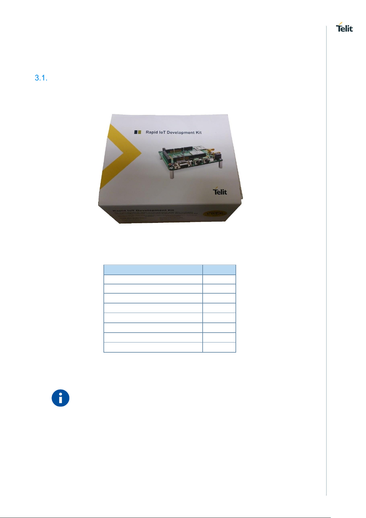
Description
Quantity
EVK4 Board
1
Cellular Antenna
1*
GPS/GLONASS Antenna
1
USB Type B cable
1
Serial cable
1
AC/DC power adapter
1
Telit IoT Connectivity SIM
1
Quick Start Guide
1
3. DESCRIPTION
EVK4 Kit Content
The below table contains the EVK4 kitting parts.
Figure 3-1 Rapid IoT Development Kit
Table 1
NOTE:
0805 Rev. 6 Page 12 of 49 2017-05-19
(*) The EVK4-LE910 V1/V2 product variant comes with two LTE antennas
for main and diversity RF input.
Page 13
Telit EVK4 HW User Guide\
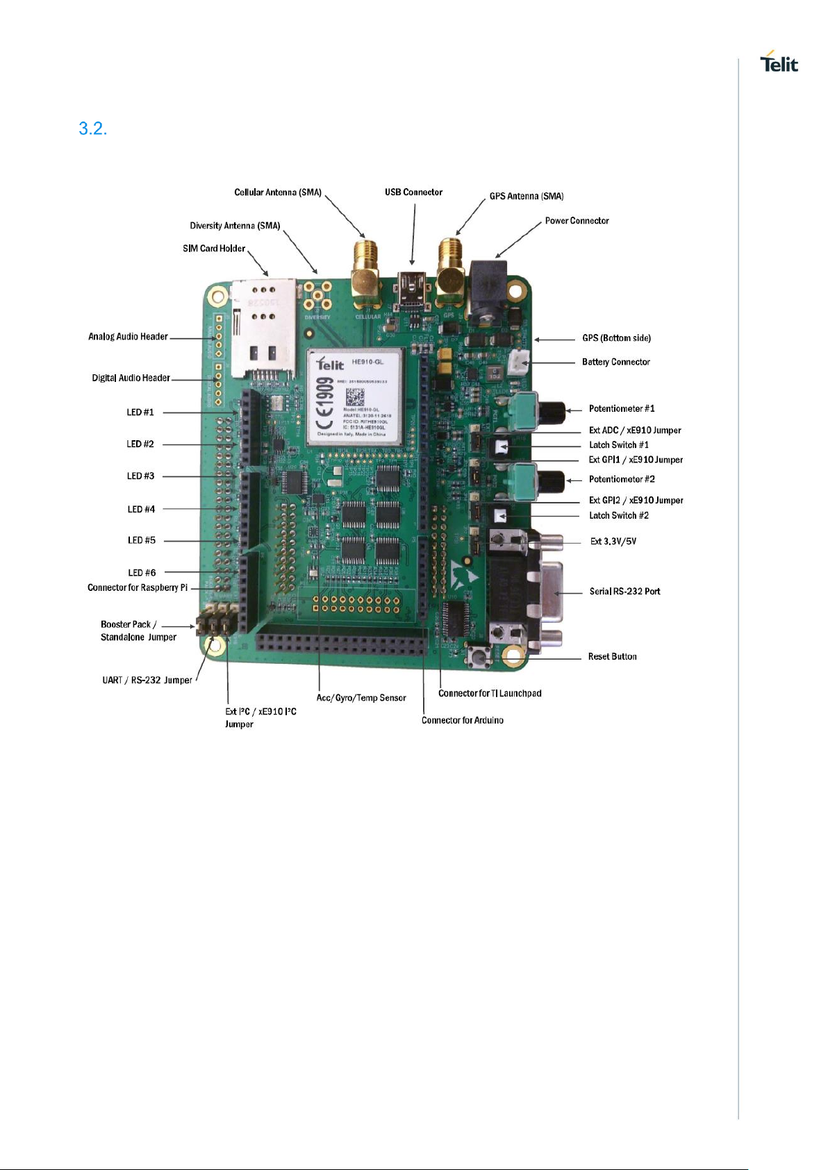
Evaluation Board
Figure 3-2 EVK4 Board
3.2.1. Mechanical Characteristics
Length 4.33 in (110.00 mm)
Width 3.70 in (94.00 mm)
Height 1.10 in (28.00 mm)
0805 Rev. 6 Page 13 of 49 2017-05-19
Page 14
Telit EVK4 HW User Guide\
Power Supply
Value
Nominal Supply Voltage
12V
Normal Operating Voltage Range
2.5V ~ 16V
Extended Operating Voltage Range
2.2V ~ 16.3V
Power Supply
Value
Nominal Supply Voltage
5V
Normal Operating Voltage Range
4.4V ~ 5.25V
Max Current Consumption USB2.0
0.5A
Max Current Consumption USB3.0*
1.5A
Power Supply
Value
Nominal Supply Voltage
3.7V
Normal Operating Voltage Range
3.1V ~ 4.2V
Battery capacity
1000mAH
4. POWER SUPPLY
Power Supply Requirements
The EVK4 can be powered by three different power sources.
4.1.1. External DC power supply. PL601 Barrel Connector
4.1.2. USB power supply. PL303 Mini-B USB Connector
4.1.3. Polymer Lithium Ion Battery. PL701 Connector
NOTE:
1. The Operating Voltage Range MUST never be exceeded. If the voltage
drop is exceeding the limits it could cause a Power Off to the cellular
module.
2. The EVK4 can source power to the add-on boards in Booster pack mode
(4.1V) mainly for portable applications with the battery.
0805 Rev. 6 Page 14 of 49 2017-05-19
Page 15
Telit EVK4 HW User Guide\
Mode
Average
(mA)
Mode Description
Switched Off
0.095
Module supplied but switched off
Sandalone mode
54.2mA
Full funcionality of the device. xE910
idle
(GPS enabled, tracking mode)
Sending data mode
494.1mA
xE910 module in Tx/Rx mode. Data
Standalone mode
14.1mA
Full funcionality of the device. xE910
idle
Sending data mode
534.2mA
xE910 module in Tx/Rx mode. Data
(GPS enabled, tracking mode)
Booster pack mode
36.5mA
(Idle, Without SIM)
BoosterPack Mode
36.2mA
(Idle, SIM, SW202/SW203 ON)
BoosterPack Mode
22.3mA
Idle, SIM, SW202/SW203 OFF
BoosterPack Mode
(Running Windows IoT)
91.7mA
Idle, SIM, RPi idle
BoosterPack Mode
(Running Windows IoT)
128.2mA
Idle, SIM, GPS, RPi idle
BoosterPack Mode
(Running Windows IoT)
257.9mA
Idle, SIM, GPS, RPi idle, HDMI-
Display
BoosterPack Mode
MSP-EXP430F5529LP
(Running LED's App)
41.3mA
Idle, SIM,
Launchpad_EXP430F5529LP
BoosterPack Mode
MSP-EXP430F5529LP
(Running LED's App)
81.9mA
Idle, SIM, GPS,
Launchpad_EXP430F5529LP
BoosterPack Mode
MSP-EXP432P401R (Running
LED's App)
110.5mA
Idle, SIM,
Launchpad_EXP432P401R
BoosterPack Mode
MSP-EXP432P401R (Running
LED's App)
157.4mA
(Idle, SIM, GPS,
Launchpad_EXP432P401R
NOTE:
(*) Is strongly recommended power the EVK4-LE910 V1/V2 product variant
through an USB3.0 port instead of USB2.0 to avoid unexpected reset issues
of the entire system.
Power Consumption
0805 Rev. 6 Page 15 of 49 2017-05-19
Page 16

Telit EVK4 HW User Guide\
Figure 5-1 Stacked on top
Figure 5-1 Stacked on top and bottom
5. ADD-ON BOARDS
The EVK4 supports three types of add-on boards: TI Launchpads, Raspberry Pi and
Arduino boards. The header connectors for the add-on boards are available on both sides
of the EVK4 allowing a stackable configuration.
The add-on boards must be inserted carefully to match the position of the EVK4 connectors,
making sure that the pin headers are vertically aligned upon among connectors upon
insertion.
Texas Instruments Launchpad
A variety of Booster Pack plug-in modules are supported through the 40-pin headers (P801
and P802). For more information about the standard and specific pinout of every Launchpad
circuit board go to: http://www.ti.com/lsds/ti/tools-software/launchpads/launchpads.page
http://www.ti.com/lit/ml/slat157/slat157.pdf
0805 Rev. 6 Page 16 of 49 2017-05-19
Page 17

Telit EVK4 HW User Guide\
Figure 5-4 EVK4 + Raspberry Pi 2
Figure 5-5 RPi board insertion
Figure 5-3 Double-stacked configuration on top
Raspberry Pi2 / Pi3
Raspberry Pi 1 Model A+, Pi 2 Model B, B+ and Pi 3 Model B are supported through the
40-pin header (PL901).
NOTE:
1. (*) Remove the standoff H1 to have access to the 2x USB-A ports that
2. The Raspberry Pi 1 Model A and B are also supported since the pinout
0805 Rev. 6 Page 17 of 49 2017-05-19
Figure 5-6 2x USB-A ports*
are on the right side of the Raspberry Pi board.
of the first 26 GPIO pins is the same than the 40-pin header, however an
extender ribbon cable would be needed to avoid any mechanical
interference with the Raspberry Pi audio connectors.
Page 18

Telit EVK4 HW User Guide\
Figure 5-7 Arduino stacked on bottom
Figure 5-8 Stacked on top and bottom
Arduino
A variety of Arduino boards and shields are supported (32 pin and 86 pin configuration)
through the ‘c’ headers (PL1001~PL1007). The Arduino boards (8-bit and 32-bit) are usually
inserted from the bottom of the EVK4 board whereas the Arduino shields are inserted on
top.
For more information about the standard and specific pinout of every Arduino board type go
to: http://www.arduino.org/products/boards
5.3.1. Arduino UNO Form Factor Boards
Be careful upon inserting the small Arduino boards like the UNO or Zero since there is a
mechanical issue with the P801 header due to the height of some components like with the
Arduino UNO where the Microcontroller (DIP package) physically interfere with the board
placement, therefore an extension headers must be used together with this type of boards.
0805 Rev. 6 Page 18 of 49 2017-05-19
Page 19

Telit EVK4 HW User Guide\
Figure 5-9 Mechanical issue with P1 Header
The EVK4 product box contains an Arduino header kit (3x8 and 1x10 pin header extensions)
to extend the pin length. Please insert the set of headers before connect the board as shown
in the below pictures.
0805 Rev. 6 Page 19 of 49 2017-05-19
Page 20

Telit EVK4 HW User Guide\
Figure 5-10 Arduino header extensions
Figure 5-11 Arduino UNO stacked
NOTE:
Each add-on board has its own GPIO configuration, thus make sure to
perform a proper setup along with the correct jumper placement to
avoid a malfunctioning of the system.
Figure 5-12 Functional solution - Arduino UNO
0805 Rev. 6 Page 20 of 49 2017-05-19
Page 21

Telit EVK4 HW User Guide\
6. JUMPERS CONFIGURATION
Principal Modes of Operation
6.1.1. Standalone Mode. PL203 Jumper
This configuration allows the cellular module be the host processor (typical application
design)
Figure 6-1 Jumper setting for Standalone Mode
6.1.2. Booster Pack Mode. PL203 Jumper
This configuration allows an external microcontroller to be the host processor. Setting the
EVK4 in Booster Pack mode will enable the TI Launchpad, Raspberry Pi 2 and Arduino host
boards to control the EVK4.
0805 Rev. 6 Page 21 of 49 2017-05-19
Page 22

Telit EVK4 HW User Guide\
Jumper Position
Description
1-2
I²C driven by an external microcontroller
2-3
I²C driven by the xE910 module
Figure 6-2 Jumper setting for Booster Pack Mode
I²C Bus
PL202: This jumper selects which master drives the I²C lines, thus selecting the I²C bus
master.
0805 Rev. 6 Page 22 of 49 2017-05-19
Page 23

Telit EVK4 HW User Guide\
Jumper Position
Description
1-2
Connects the USIF0 to the external microcontroller
headers. This is the typical position for Booster Pack
mode.
2-3
Connects the USIF0 to the RS232 DB9 connector.
This is the typical position for Standalone mode
Figure 6-3 Jumper setting for I²C driven by the xE910 module
UART1 (xE910 USIF0)
PL304: This jumper selects whether the USIF0 UART on the xE910 module is connected
to the RS232 DB9 connector, or if it is routed to a UART on an external microcontroller.
Figure 6-4 Jumper setting to type AT commands
through the PC connected to the RS232 port
0805 Rev. 6 Page 23 of 49 2017-05-19
Page 24

Telit EVK4 HW User Guide\
Jumper Position
Description
1-2
Connects SW203 to a general purpose interrupt pin (GPI1)
on the external microcontroller
2-3
Connects SW203 to the xE910 module
Jumper Position
Description
1-2
Connects SW202 to a general purpose interrupt pin
(GPI2) on the external microcontroller
2-3
Connects SW202 to the xE910 module
Push Switch1 - SW203
PL208: This jumper connects the digital output of push switch #1 (‘1’ logic or ’0’ logic) to
either the xE910 module or an external microcontroller.
Figure 6-5 Jumper setting to connect the SW203 output to the xE910 module
Push Switch2 – SW202
PL207: This jumper connects the digital output of push switch #2 (‘1’ logic or ’0’ logic) to
either the xE910 module or an external microcontroller.
0805 Rev. 6 Page 24 of 49 2017-05-19
Page 25

Telit EVK4 HW User Guide\
Jumper Position
Description
1-2
Connects POT1 to an external ADC on the
microcontroller headers
2-3
Connects POT1 to the ADC_IN1 input on xE910
module
Figure 6-6 Jumper setting to connect the S3 output to the xE910 module
Potentiometer1 – POT1
PL206: This jumper connects potentiometer #1 to either the xE910 module or an external
microcontroller.
NOTE:POT2 is useless in Standalone mode because the xE910 module only has one ADC.
Figure 6-7 Jumper setting to connect the POT1 to the xE910 module
0805 Rev. 6 Page 25 of 49 2017-05-19
Page 26

Telit EVK4 HW User Guide\
Jumper Position
Description
1-2
Source 5V for the Analog reference. AVCC
2-3
Source 3.3V for the Analog reference. AVCC
Booster Pack ADC VREF
PL602: When in Booster Pack mode, this jumper selects the external voltage reference for
the POT1 and POT2.
Figure 6-8 Jumper setting to select 3.3V as VREF for the ADC
NOTE: The Voltage Reference for the ADC has no effect in Standalone mode.
0805 Rev. 6 Page 26 of 49 2017-05-19
Page 27

Telit EVK4 HW User Guide\
LED
Color
Description
201
Green
xE910 Network Service Status / General Purpose GPIO*
202
Red
xE910 VAUX/PWRMON. Is used as indicator to
determine whether or not the xE910 module is powered on.
203
Blue
Built-in GPS Status / General Purpose
204
Yellow
General Purpose
205
Red
General Purpose
501
Blue
PPS SL869**
701
Green
Battery Charge Status – PG
702
Yellow
Battery Charge Status – CHG
7. OPTICAL INDICATORS
LEDs description
The EVK4 has 8 optical indicators LED1~LED8.
(*) Can be programmable only in Standalone mode. Type the AT#GPIO=1,0,2 for enable Network Status LED.
(**) Only available for the LE910-V2, HE910-GL and UE910 variants
Figure 7-1 LED201, LED202, LED203, LED204, LED205, LED501.
Figure 7-2 LED701, LED702.
0805 Rev. 6 Page 27 of 49 2017-05-19
Page 28

Telit EVK4 HW User Guide\
LED
xE910
Standalone
Mode
TI Launchpad
(Headers P801, P802)
Raspberry
Pi
(Header PL901)
Arduino
(Headers
PL1001~PL1007)
201
GPIO_01
N/A
N/A
N/A
203
GPIO_08*
J4.40
(P802.1)
GPIO20
(PL901.38)
IO13
(PL1006.6)
204
GPIO_09
J4.39
(P802.3)
GPIO18
(PL901.12)
IO12
(PL1006.5)
205
GPIO_10
J4.38
(P802.5)
GPIO21
(PL901.40)
IO10
(PL1006.3)
Charge status
LED701 (PG) green
LED702 (CHG)
yellow
1’st Charge
---
ON
Refresh charge
---
OFF
OVP
OFF
OFF
SLEEP
OFF
OFF
TEMP FAULT
---
ON (1’st charge)
UVLO
OFF
---
Normal Input
ON
---
Programmable LEDs
These are the GPIOs that should be configured to drive the General Purpose LEDs:
(*) Can be programmable only in Standalone mode.
Charge Status LED
The LED701 and LED702 will have the following behavior upon charging the Li-Pol
battery.
*PG is independent of chip disable
0805 Rev. 6 Page 28 of 49 2017-05-19
Page 29

Telit EVK4 HW User Guide\
I²C
xE910
Standalone Mode
TI Launchpad
(Headers P801, P8022)
Raspberry Pi
(Header PL901)
Arduino
(Headers
PL1001~PL1007)
SDA
GPIO_02
J1.10
(P801.19)
GPIO2
(PL901.3)
SDA
(PL1006.9)
SCL
GPIO_03
J1.9
(P801.17)
GPIO3
(PL901.5)
SCL
(PL1006.10)
Part Number
Description
LSM6DS3
Accelerometer/Gyro/Temperature Sensor (U403)
HDC1080*
Humidity Sensor (U401)
LPS25H*
Pressure Sensor (U402)
LC709203F
Battery monitor (U702)
OPT3001DNP
Optical Sensor (U406)
INT1
xE910
Standalone Mode
TI Launchpad
(Headers P801, P802)
Raspberry Pi
(Header PL901)
Arduino
(Headers
PL1001~PL1007)
U403
GPIO_06
J4.36
(P802.9)
GPIO16
(PL901.36)
IO3
(PL1005.4)
U402
GPIO_07
J4.35
(P802.11)
GPIO24
(PL901.18)
IO2
(PL1005.3)
U406
DSR as GPIO
J3.24
(P801.8)
GPIO4
(PL901.7)
ADC8
(PL1003.1)
8. SENSORS
I²C Bus
All the sensors and battery monitor are connected to the I²C bus, therefore the I²C lines
shall be configured correctly to establish a proper communication.
NOTE:
SDA and SCL lines have 10KΩ pull-up resistors.
List of Sensors, Battery Monitor
NOTE:(*) Some sensors are not populated by default. Ask to the technical
support for the complete BOM if you want to mount the sensors
Sensor Interrupt Lines
The LSM6DS3 and LPS25H, and OPT3001DNP have an output (INT) that can be used as
Interrupt line
0805 Rev. 6 Page 29 of 49 2017-05-19
Page 30

Telit EVK4 HW User Guide\
POT
xE910
Standalone Mode
TI Launchpad
(Headers P801, P802)
Raspberry
Pi
(Header PL901)
Arduino
(Headers
PL1001~PL1007)
POT1
ADC_IN1
J1.2
(P801.3)
N/A*
(PL901.35)
ADC0
(PL1002.1)
POT2
N/A
J1.6
(P801.11)
N/A*
(PL901.37)
ADC1
(PL1002.2)
Switch
xE910
Standalone Mode
TI Launchpad
(Headers P801, P802)
Raspberry
Pi
(Header PL901)
Arduino
(Headers P4~P10)
SW203
GPIO_04
J1.5
(P801.9)
GPIO6
(PL901.31)
IO/ADC3
(PL1002.4)
SW202
GPIO_05
J1.8
(P801.15)
GPIO13
(PL901.33)
IO11
(PL1006.4)
9. MISCELANEOUS
Potentiometers
The EVK4 has two potentiometers of 10KΩ.
The PL206 jumper should be configured based on the mode of operation (Refer to chapter
6.6).
Guidelines
Push-Button Switches
The EVK4 has two push button switches that are latched (On-On) to set a ‘1’ logic or ’0’
logic.
The PL208 and PL207 jumpers should be configured based on the mode of operation
(Refer to chapter 6.4 and 6.5).
.
Guidelines
0805 Rev. 6 Page 30 of 49 2017-05-19
Page 31

Telit EVK4 HW User Guide\
UART
xE910
Standalone Mode
TI Launchpad
(Headers P801, P802)
Raspberry
Pi
(Header PL901)
Arduino
(Headers
PL1001~PL1007)
TX
TXD
J1.3
(P801.5)
GPIO15
(PL901.10)
RXD
(PL1005.1)
RX
RXD
J1.4
(P801.7)
GPIO14
(PL901.8)
TXD
(PL1005.2)
RTS
RTS
J2.14
(P802.14)
GPIO8
(PL901.24)
IO6
(PL1005.5)
CTS
CTS
J2.12
(P802.18)
GPIO25
(PL901.22)
IO4
(PL1005.7)
10. UART1 (USIF0)
This is the configuration to have serial communication with the xE910 module through the
UART1.
0805 Rev. 6 Page 31 of 49 2017-05-19
Page 32

Telit EVK4 HW User Guide\
COMPONENT
STANDALONE
BOOSTERPACK
PL203
2-3
1-2
PL202
2-3
1-2
PL208
2-3
1-2
PL207
2-3
1-2
PL206
2-3
1-2
PL304
2-3
1-2
PL303
2-3
1-2
11. STANDALONE\BOOSTERPACK JUMPER
CONFIGURATION
In order to use the Board in STAND-ALONE or BOOSTERPACK configurations the jumpers
should be configured as follow.
Figure 11.1 STANDALONE complete jumpers configuration
0805 Rev. 6 Page 32 of 49 2017-05-19
Page 33

Telit EVK4 HW User Guide\
Figure 11.2 BOOSTERPACK complete jumpers configuration
0805 Rev. 6 Page 33 of 49 2017-05-19
Page 34

Telit EVK4 HW User Guide\
12. SCHEMATICS
EVK4_MAIN
0805 Rev. 6 Page 34 of 49 2017-05-19
Page 35

Telit EVK4 HW User Guide\
HE910-GL_MODULE
0805 Rev. 6 Page 35 of 49 2017-05-19
Page 36

Telit EVK4 HW User Guide\
EXTERNAL_PORTS
0805 Rev. 6 Page 36 of 49 2017-05-19
Page 37

Telit EVK4 HW User Guide\
SENSORS
0805 Rev. 6 Page 37 of 49 2017-05-19
Page 38

Telit EVK4 HW User Guide\
GPS_SL869
0805 Rev. 6 Page 38 of 49 2017-05-19
Page 39

Telit EVK4 HW User Guide\
DC_DC_POWER_SUPPLY
0805 Rev. 6 Page 39 of 49 2017-05-19
Page 40

Telit EVK4 HW User Guide\
BATTERY_CHARGER_MONITOR
0805 Rev. 6 Page 40 of 49 2017-05-19
Page 41

Telit EVK4 HW User Guide\
TI_LAUNCHPAD_HEADER
0805 Rev. 6 Page 41 of 49 2017-05-19
Page 42

Telit EVK4 HW User Guide\
RASPBERRY_PI_HEADER
0805 Rev. 6 Page 42 of 49 2017-05-19
Page 43

Telit EVK4 HW User Guide\
ARDUINO_HEADER
0805 Rev. 6 Page 43 of 49 2017-05-19
Page 44

Telit EVK4 HW User Guide\
13. CONFORMITY ASSESSMENT ISSUES
FCC/IC Regulatory notices
Modification statement
Telit has not approved any changes or modifications to this device by the user. Any changes
or modifications could void the user’s authority to operate the equipment.
Telit n’approuve aucune modification apportée à l’appareil par l’utilisateur, quelle qu’en soit
la nature. Tout changement ou modification peuvent annuler le droit d’utilisation de
l’appareil par l’utilisateur.
Interference statement
The xE910 module populated on the EVK4 complies with Part 15 of the FCC Rules and
Industry Canada licence-exempt RSS standard(s).
Operation is subject to the following two conditions: (1) this device may not cause
interference, and (2) this device must accept any interference, including interference that
may cause undesired operation of the device.
Le module xE910 installé sur l’EVK4 est conforme aux CNR d'Industrie Canada applicables
aux appareils radio exempts de licence.
L'exploitation est autorisée aux deux conditions suivantes : (1) l'appareil ne doit pas
produire de brouillage, et (2) l'utilisateur de l'appareil doit accepter tout brouillage
radioélectrique subi, même si le brouillage est susceptible d'en compromettre le
fonctionnement.
0805 Rev. 6 Page 44 of 49 2017-05-19
Page 45

Telit EVK4 HW User Guide\
14. SAFETY RECOMMENDATIONS
READ CAREFULLY
Be sure the use of this product is allowed in the country and in the environment required.
The use of this product may be dangerous and has to be avoided in the following areas:
Where it can interfere with other electronic devices in environments such as
hospitals, airports, aircrafts, etc.
Where there is risk of explosion such as gasoline stations, oil refineries, etc. It is the
responsibility of the user to enforce the country regulation and the specific
environment regulation.
Do not disassemble the product; any mark of tampering will compromise the warranty
validity. We recommend following the instructions of the hardware user guides for correct
wiring of the product. The product has to be supplied with a stabilized voltage source and
the wiring has to be conformed to the security and fire prevention regulations. The product
has to be handled with care, avoiding any contact with the pins because electrostatic
discharges may damage the product itself. Same cautions have to be taken for the SIM,
checking carefully the instruction for its use. Do not insert or remove the SIM when the
product is in power saving mode.
The system integrator is responsible for the functioning of the final product; therefore, care
has to be taken to the external components of the module, as well as any project or
installation issue, because the risk of disturbing the GSM network or external devices or
having impact on the security. Should there be any doubt, please refer to the technical
documentation and the regulations in force. Every module has to be equipped with a proper
antenna with specific characteristics. The antenna has to be installed with care in order to
avoid any interference with other electronic devices and has to guarantee a minimum
distance from the body (20 cm). In case this requirement cannot be satisfied, the system
integrator has to assess the final product against the SAR regulation.
The European Community provides some Directives for the electronic equipment
introduced on the market. All of the relevant information is available on the European
Community website:
http://ec.europa.eu/enterprise/sectors/rtte/documents/
The text of the Directive 99/05 regarding telecommunication equipment is available,
while the applicable Directives (Low Voltage and EMC) are available at:
http://ec.europa.eu/enterprise/sectors/electrical/
0805 Rev. 6 Page 45 of 49 2017-05-19
Page 46

Telit EVK4 HW User Guide\
TTSC
Telit Technical Support Centre
USB
Universal Serial Bus
HS
High Speed
DTE
Data Terminal Equipment
DCE
Data Communication Equipment
UMTS
Universal Mobile Telecommunication System
WCDMA
Wideband Code Division Multiple Access
HSDPA
High Speed Downlink Packet Access
HSUPA
High Speed Uplink Packet Access
LTE
Long-Term Evolution
GPS
Global Position System
GNSS
Global Navigation Satellite System
UART
Universal Asynchronous Receiver Transmitter
SIM
Subscriber Identification Module
I²C
Inter-Integrated Circuit
SDA
Serial Data - I²C
SCL
Serial Clock - I²C
ADC
Analog – Digital Converter
DAC
Digital – Analog Converter
I/O
Input Output
GPIO
General Purpose Input Output
15. ACRONYMS
0805 Rev. 6 Page 46 of 49 2017-05-19
Page 47

Telit EVK4 HW User Guide\
CMOS
Complementary Metal – Oxide Semiconductor
SPI
Serial Peripheral Interface
MOSI
Master Output – Slave Input
MISO
Master Input – Slave Output
CLK
Clock
MRDY
Master Ready
SRDY
Slave Ready
CS
Chip Select
RTC
Real Time Clock
PCB
Printed Circuit Board
ESR
Equivalent Series Resistance
VSWR
Voltage Standing Wave Radio
LED
Light-Emitting Diode
RS-232
Standard for Serial Communication transmission of data
POT
Potentiometer
SMA
SubMiniature version A connector
EVK
Telit Evaluation Kit
RPi
Raspberry Pi
TI
Texas Instruments
0805 Rev. 6 Page 47 of 49 2017-05-19
Page 48

Telit EVK4 HW User Guide\
Revision
Date
Changes
0
2016-10-26
First issue
16. DOCUMENT HISTORY
0805 Rev. 6 Page 48 of 49 2017-05-19
Page 49

Mod. 0805 2016-08 Rev.5
 Loading...