

Page 1

Telit EVK2 User Guide
1vv0300704 Rev.17 - 2013/05/30
Page 2
Model
Part Number
Engine
EVK2
3990150474
Mother Board
EVK2-M2MAIR
3990150502
Mother Board + m2mAIR SIM
GM862 INTERFACE
3990250670
GM862
GE863-PY INTERFACE
3990250684
GE863-PY
GE863-GPS INTERFACE
3990250696
GE863-GPS
GE863-SIM INTERFACE
3990250703
GE863-SIM
GE864-PY INTERFACE
3990250672
GE864-PY
GE864-QUAD V2 INTERFACE
3990250777
GE864-QUAD V2
GE864-DUAL V2 INTERFACE
3990250778
GE864-DUAL V2
GE864-QUAD AUTOMOTIVE V2 INTERFACE
3990250773
GE864-QUAD AUTOMOTIVE V2
GE864-QUAD ATEX V2 INTERFACE
3990250772
GE864-QUAD ATEX V2
GE864-QUAD SIM V2 INTERFACE
3990250771
GE864-QUAD SIM V2
GE864-GPS INTERFACE
3990250820
3990250822
GE864-GPS
GC864 INTERFACE
3990250680
GC864
GC864-QUAD-C2 INTERFACE
3990250683
GC864-QUAD-C2
GE865-QUAD INTERFACE
3990250766
GE865-QUAD
GE865/SE867-AGPS INTERFACE
3990250814
GE865-QUAD
GE865/JF2 INTERFACE
3990250868
3990250954
GE865-QUAD
GL865-QUAD INTERFACE
3990250812
GL865-QUAD
GL865-DUAL INTERFACE
3990250783
GL865-DUAL
GL868-DUAL INTERFACE
3990250790
GL868-DUAL
UC864 INTERFACE
4990150470
UC864
Telit EVK2 User Guide
1vv0300704 Rev.17 – 2013/05/30
APPLICABILITY LIST:
GL865/JN3 INTERFACE
Reproduction forbidden without Telit Communications S.p.A. written authorization - All Rights Reserved page 2 of 243
3990250821
GL865-QUAD
Page 3

HE863-EUR INTERFACE
3990250797
HE863
HE863-EUG INTERFACE
3990250798
HE863
HE863-NAD INTERFACE
3990250799
HE863
HE863-NAR INTERFACE
3990250800
HE863
HE863-NAG INTERFACE
3990250801
HE863
HE863-AUR INTERFACE
3990250803
HE863
HE863-AUG INTERFACE
3990250804
HE863
HE910 INTERFACE
3990250845
HE910
UE910-EUR INTERFACE
3990250918
UE910-EUR
UE910-NAR INTERFACE
3990250919
UE910-NAR
GE910 INTERFACE
3990250882
GE910
GE910-GNSS INTERFACE
3990250941
GE910-GNSS
GE910-QUAD V3 INTERFACE
3990251006
GE910-QUAD V3
3990250886
CE910 INTERFACE
3990250887
CE910
GL865-DUAL V3 1.8V INTERFACE
3990250948
GL865-DUAL V3
LE920-EU INTERFACE
3990251000
LE920-EU
LE920-NA INTERFACE
3990250999
LE920-NA
Telit EVK2 User Guide
1vv0300704 Rev.17 – 2013/05/30
DE910 INTERFACE
DE910
Reproduction forbidden without Telit Communications S.p.A. written authorization - All Rights Reserved page 3 of 243
Page 4

Telit EVK2 User Guide
1vv0300704 Rev.17 – 2013/05/30
SPECIFICATIONS SUBJECT TO CHANGE WITHOUT NOTICE
Notice
While reasonable efforts have been made to assure the accuracy of this document, Telit
assumes no liability resulting from any inaccuracies or omissions in this document, or from
use of the information obtained herein. The information in this document has been carefully
checked and is believed to be entirely reliable. However, no responsibility is assumed for
inaccuracies or omissions. Telit reserves the right to make changes to any products described
herein and reserves the right to revise this document and to make changes from time to time
in content hereof with no obligation to notify any person of revisions or changes. Telit does
not assume any liability arising out of the application or use of any product, software, or
circuit described herein; neither does it convey license under its patent rights or the rights of
others.
It is possible that this publication may contain references to, or information about Telit
products (machines and programs), programming, or services that are not announced in your
country. Such references or information must not be construed to mean that Telit intends to
announce such Telit products, programming, or services in your country.
Copyrights
This instruction manual and the Telit products described in this instruction manual may be,
include or describe copyrighted Telit material, such as computer programs stored in
semiconductor memories or other media. Laws in the Italy and other countries preserve for
Telit and its licensors certain exclusive rights for copyrighted material, including the
exclusive right to copy, reproduce in any form, distribute and make derivative works of the
copyrighted material. Accordingly, any copyrighted material of Telit and its licensors
contained herein or in the Telit products described in this instruction manual may not be
copied, reproduced, distributed, merged or modified in any manner without the express
written permission of Telit. Furthermore, the purchase of Telit products shall not be deemed
to grant either directly or by implication, estoppel, or otherwise, any license under the
copyrights, patents or patent applications of Telit, as arises by operation of law in the sale of
a product.
Computer Software Copyrights
rd
The Telit and 3
may include copyrighted Telit and other 3
semiconductor memories or other media. Laws in the Italy and other countries preserve for
Telit and other 3
programs, including the exclusive right to copy or reproduce in any form the copyrighted
computer program. Accordingly, any copyrighted Telit or other 3
Party supplied Software (SW) products described in this instruction manual
rd
Party supplied SW certain exclusive rights for copyrighted computer
rd
Party supplied computer programs stored in
rd
Party supplied SW
computer programs contained in the Telit products described in this instruction manual may
not be copied (reverse engineered) or reproduced in any manner without the express written
permission of Telit or the 3
shall not be deemed to grant either directly or by implication, estoppel, or otherwise, any
license under the copyrights, patents or patent applications of Telit or other 3
rd
Party SW supplier. Furthermore, the purchase of Telit products
rd
Party
Reproduction forbidden without Telit Communications S.p.A. written authorization - All Rights Reserved page 4 of 243
Page 5

Telit EVK2 User Guide
1vv0300704 Rev.17 – 2013/05/30
supplied SW, except for the normal non-exclusive, royalty free license to use that arises by
operation of law in the sale of a product.
Usage and Disclosure Restrictions
License Agreements
The software described in this document is the property of Telit and its licensors. It is
furnished by express license agreement only and may be used only in accordance with the
terms of such an agreement.
Copyrighted Materials
Software and documentation are copyrighted materials. Making unauthorized copies is
prohibited by law. No part of the software or documentation may be reproduced,
transmitted, transcribed, stored in a retrieval system, or translated into any language or
computer language, in any form or by any means, without prior written permission of Telit
High Risk Materials
Components, units, or third-party products used in the product described herein are NOT
fault-tolerant and are NOT designed, manufactured, or intended for use as on-line control
equipment in the following hazardous environments requiring fail-safe controls: the
operation of Nuclear Facilities, Aircraft Navigation or Aircraft Communication Systems, Air
Traffic Control, Life Support, or Weapons Systems (High Risk Activities”). Telit and its
supplier(s) specifically disclaim any expressed or implied warranty of fitness for such High
Risk Activities.
Trademarks
TELIT and the Stylized T Logo are registered in Trademark Office. All other product or
service names are the property of their respective owners.
Copyright © Telit Communications S.p.A.
Reproduction forbidden without Telit Communications S.p.A. written authorization - All Rights Reserved page 5 of 243
Page 6

Telit EVK2 User Guide
1vv0300704 Rev.17 – 2013/05/30
Contents
1. Introduction ............................................................................................................................. 15
1.1. Scope .................................................................................................................................................... 15
1.2. Audience .............................................................................................................................................. 15
1.3. Contact Information, Support ........................................................................................................... 15
1.4. Text Conventions ................................................................................................................................ 16
1.5. Related Documents ............................................................................................................................. 16
1.6. Content of the kit ................................................................................................................................ 17
2. Description ............................................................................................................................... 18
2.1. PCB characteristics ............................................................................................................................ 19
2.2. Mechanical characteristics of the assembled PCBs ......................................................................... 20
2.2.1. Mother Board CS1139B ................................................................................................................... 20
2.2.2. GM862 Interface CS1150B ................................................................................................................. 20
2.2.3. GE863 Interface CS1151A .................................................................................................................. 20
2.2.4. GE864 Interface CS1152B .................................................................................................................. 20
2.2.5. GE864-GPS Interface CS1439B .......................................................................................................... 20
2.2.6. GC864 Interface CS1203B .................................................................................................................. 21
2.2.7. GC864-C2 Interface CS1231X ............................................................................................................. 21
2.2.8. GE865 Interface CS1324A .................................................................................................................. 21
2.2.9. GE865/SE867-AGPS Interface CS1433 .............................................................................................. 21
2.2.10. GE865/JF2 Interface CS1521 .............................................................................................................. 21
2.2.11. GL865 Interface CS1431A .................................................................................................................. 21
2.2.12. UC864-CC864 Interface KS0101C ........................................................................................................ 21
2.2.13. HE910 Interface CS1467C ..................................................................................................................... 22
2.2.14. UE910 Interface CS1467D ..................................................................................................................... 22
2.2.15. GE910 Interface CS1467D ..................................................................................................................... 22
2.2.16. GE910-GNSS Interface CS1467F .......................................................................................................... 22
2.2.17. GE910-QUAD V3 Interface CS1467F ................................................................................................... 22
2.2.18. DE910 Interface CS1467D ..................................................................................................................... 22
2.2.19. CE910 Interface CS1467D ..................................................................................................................... 22
2.2.20. GL865 V3 Interface CS1531B ................................................................................................................ 23
2.2.21. LE920 Interface KS0145B ...................................................................................................................... 23
3. Startup procedure ................................................................................................................... 24
4. Insertion of the Interface Boards ........................................................................................... 25
5. Power supply setting ............................................................................................................... 26
5.1. Fixed DC source .................................................................................................................................. 26
5.2. Variable DC source ............................................................................................................................ 27
5.2.1. Coaxial Plug ............................................................................................................................................ 28
5.3. Li-Ion Battery pack and Charger ..................................................................................................... 28
5.4. Application Notes ............................................................................................................................... 29
5.4.1. Li-Ion Battery Pack ................................................................................................................................. 29
Reproduction forbidden without Telit Communications S.p.A. written authorization - All Rights Reserved page 6 of 243
Page 7

Telit EVK2 User Guide
1vv0300704 Rev.17 – 2013/05/30
5.4.2. About Current Charger ........................................................................................................................... 29
6. Serial interface ........................................................................................................................ 30
6.1. Serial Port Setup ................................................................................................................................. 31
7. Audio Section ........................................................................................................................... 32
7.1. Overview ............................................................................................................................................. 32
7.1.1. History .................................................................................................................................................... 32
7.2. Actual ................................................................................................................................................... 33
7.2.1. The choice ............................................................................................................................................... 33
7.3. Differential and Single Ended ........................................................................................................... 33
7.3.1. Concepts ................................................................................................................................................. 33
7.3.2. Benefits and disadvantages ..................................................................................................................... 34
7.3.3. Settings ................................................................................................................................................... 35
8. AF Amplifiers Setting ............................................................................................................. 36
9. Audio outputs .......................................................................................................................... 37
9.1. Low AF Power Mode ......................................................................................................................... 37
9.2. High AF Power Mode ......................................................................................................................... 38
9.2.1. Speaker and Stand-alone Microphone .................................................................................................... 39
9.2.2. Speaker plus Headset .............................................................................................................................. 40
10. Audio Accessories ................................................................................................................ 41
10.1. Headset ................................................................................................................................................ 41
10.2. Stand-alone microphone .................................................................................................................... 42
10.3. Speaker ................................................................................................................................................ 42
11. Indication and services ........................................................................................................ 43
11.1. Optical Indicators ............................................................................................................................... 43
11.1.1. Status Led ............................................................................................................................................... 43
11.1.2. CHARGE Led ......................................................................................................................................... 44
11.2. Switches ............................................................................................................................................... 45
11.2.1. POWER ON Switch ................................................................................................................................ 45
11.2.2. RESET Switch ........................................................................................................................................ 45
12. Connectors pinout ............................................................................................................... 46
12.1. Motherboard to Module .................................................................................................................... 46
13. Module Interface Boards .................................................................................................... 49
13.1. Generality ............................................................................................................................................ 49
13.2. Short Description ................................................................................................................................ 49
13.3. Further Accessories for GPS version ................................................................................................ 49
14. GM862 Interface ................................................................................................................. 50
Reproduction forbidden without Telit Communications S.p.A. written authorization - All Rights Reserved page 7 of 243
Page 8

Telit EVK2 User Guide
1vv0300704 Rev.17 – 2013/05/30
14.1. Stand-alone setup ............................................................................................................................... 50
14.2. Interface connectors ........................................................................................................................... 51
14.3. Content of the kit ................................................................................................................................ 51
15. GE863 Interface ................................................................................................................... 52
15.1. Stand-alone setup ............................................................................................................................... 52
15.2. Content of the kits .............................................................................................................................. 53
15.2.1. GE863-PY/QUAD version ..................................................................................................................... 53
15.2.2. GE863-GPS version ................................................................................................................................ 53
15.2.3. GE863-SIM version ................................................................................................................................ 53
15.3. Interface connectors ........................................................................................................................... 53
15.4. Additional components for GPS version .......................................................................................... 53
15.5. USB connector .................................................................................................................................... 54
15.6. Serial port configuration .................................................................................................................... 55
15.6.1. GE863-PY/QUAD .................................................................................................................................. 55
15.6.2. GE863 – GPS .......................................................................................................................................... 56
15.7. ANTENNA connectors ....................................................................................................................... 57
15.7.1. GPS ANTENNA connector .................................................................................................................... 57
15.7.2. GSM ANTENNA connector ................................................................................................................... 57
15.7.3. RFU ANTENNA connector .................................................................................................................... 57
16. GE864 Interface ................................................................................................................... 58
16.1. Stand-alone setup ............................................................................................................................... 58
16.2. Interface connectors ........................................................................................................................... 59
16.3. Content of the kit ................................................................................................................................ 59
17. GE864-GPS Interface ......................................................................................................... 60
17.1. Part numbering................................................................................................................................... 60
17.2. Stand-alone setup ............................................................................................................................... 61
17.3. Interface connectors ........................................................................................................................... 61
17.4. Contents of the kit .............................................................................................................................. 61
17.5. Power supply ....................................................................................................................................... 62
17.6. GPS external LNA enable signal ....................................................................................................... 62
17.7. Serial port configuration .................................................................................................................... 63
17.7.1. ASC1 to RS-232 ..................................................................................................................................... 64
17.7.2. GPS to ASC1 (internal host controlling configuration) .......................................................................... 64
17.7.3. GPS to RS-232 (external host controlling configuration) ....................................................................... 65
17.7.4. GPS to USB ............................................................................................................................................ 65
17.8. GPIO settings ...................................................................................................................................... 66
17.8.1. Internal host controlling configuration ................................................................................................... 66
Reproduction forbidden without Telit Communications S.p.A. written authorization - All Rights Reserved page 8 of 243
Page 9

Telit EVK2 User Guide
1vv0300704 Rev.17 – 2013/05/30
17.8.2. External host controlling configuration .................................................................................................. 67
17.9. Antenna connectors ............................................................................................................................ 69
17.9.1. GSM antenna connector .......................................................................................................................... 69
17.9.2. GPS antenna connector ........................................................................................................................... 69
18. GE865 – SE867 AGPS Interface ........................................................................................ 70
18.1. Stand-alone setup ............................................................................................................................... 70
18.2. Interface connectors ........................................................................................................................... 71
18.3. Contents of the kit .............................................................................................................................. 71
18.3.1. GSM to GPS (GSM controlling configuration) ...................................................................................... 72
18.3.2. GSM to Trace ......................................................................................................................................... 73
18.3.3. GPS to Trace(external host controlling configuration) ........................................................................... 74
18.4. Antenna connectors ............................................................................................................................ 74
18.4.1. GSM antenna connector .......................................................................................................................... 74
18.4.2. GPS antenna connector ........................................................................................................................... 74
19. GE865 – JF2 Interface ........................................................................................................ 75
19.1. Stand-alone setup ............................................................................................................................... 75
19.2. Interface connectors ........................................................................................................................... 76
19.3. Contents of the kit .............................................................................................................................. 76
19.4. Power supply ....................................................................................................................................... 76
19.5. GPS external LNA enable signal ....................................................................................................... 77
19.6. Serial port configuration .................................................................................................................... 79
19.7. GSM to Trace...................................................................................................................................... 80
19.8. GPS to Trace ....................................................................................................................................... 80
19.9. GSM to USB ........................................................................................................................................ 81
19.10. GPS to USB ......................................................................................................................................... 81
19.11. GPS to GSM (internal host controlling configuration) ................................................................... 82
19.12. GPIO settings ...................................................................................................................................... 82
19.12.1. Internal host controlling configuration ................................................................................................... 83
19.12.2. External host controlling configuration .................................................................................................. 84
19.13. GPS serial interface setting ............................................................................................................... 85
19.14. MEMS Sensor/EEPROM Interface .................................................................................................. 85
19.15. GPS power-on management .............................................................................................................. 85
19.16. Antenna connectors ............................................................................................................................ 86
19.16.1. GSM antenna connector .......................................................................................................................... 86
19.16.2. GPS antenna connector ........................................................................................................................... 86
20. GL865 – SL869/JN3 Interface ............................................................................................ 87
Reproduction forbidden without Telit Communications S.p.A. written authorization - All Rights Reserved page 9 of 243
Page 10

Telit EVK2 User Guide
1vv0300704 Rev.17 – 2013/05/30
20.1. Stand-alone setup ............................................................................................................................... 88
20.2. Interface connectors ........................................................................................................................... 88
20.3. Contents of the kit .............................................................................................................................. 88
20.1. Power supply ....................................................................................................................................... 89
20.2. GPS external LNA enable signal ....................................................................................................... 90
20.3. Serial port configuration .................................................................................................................... 91
20.4. GSM to Trace...................................................................................................................................... 92
20.5. GPS to Trace ....................................................................................................................................... 92
20.6. GSM to USB ........................................................................................................................................ 93
20.7. GPS to USB ......................................................................................................................................... 93
20.8. GPS to GSM (internal host controlling configuration) ................................................................... 94
20.9. GPIO settings ...................................................................................................................................... 95
20.9.1. Internal host controlling configuration ................................................................................................... 95
20.9.2. External host controlling configuration .................................................................................................. 96
20.10. Antenna connectors ............................................................................................................................ 97
20.10.1. GSM antenna connector .......................................................................................................................... 97
20.10.2. GPS antenna connector ........................................................................................................................... 97
21. GC864 Interface .................................................................................................................. 98
21.1. Stand-alone setup ............................................................................................................................... 98
21.2. Interface connectors ........................................................................................................................... 99
21.3. Content of the kit ................................................................................................................................ 99
22. GC864-C2 family Interface .............................................................................................. 100
22.1. Stand-alone setup ............................................................................................................................. 100
22.2. Interface connectors ......................................................................................................................... 101
22.3. Content of the kit .............................................................................................................................. 101
23. GE865 Interface ................................................................................................................. 102
23.1. Stand-alone setup ............................................................................................................................. 102
23.2. Interface connectors ......................................................................................................................... 103
23.3. Content of the kit .............................................................................................................................. 103
24. GL865 Interface ................................................................................................................. 104
24.1. Stand-alone setup ............................................................................................................................. 104
24.2. Interface connectors ......................................................................................................................... 105
24.3. Content of the kit .............................................................................................................................. 105
25. UC864 family Interface ..................................................................................................... 106
Reproduction forbidden without Telit Communications S.p.A. written authorization - All Rights Reserved page 10 of 243
Page 11

Telit EVK2 User Guide
1vv0300704 Rev.17 – 2013/05/30
25.1. Stand-alone setup ............................................................................................................................. 106
25.2. Interface connectors ......................................................................................................................... 107
25.3. Content of the kit .............................................................................................................................. 107
26. HE910 family Interface ..................................................................................................... 108
26.1. Stand-alone setup ............................................................................................................................. 109
26.2. Interface connectors ......................................................................................................................... 109
26.3. Antenna connectors .......................................................................................................................... 110
26.3.1. GSM/UMTS Antenna connector .......................................................................................................... 110
26.3.2. Receiver Diversity Antenna connector ................................................................................................. 110
26.3.3. GPS antenna connector ......................................................................................................................... 110
26.4. Expansion Connectors ..................................................................................................................... 111
26.4.1. PL301/PL302 ........................................................................................................................................ 111
26.4.2. PL303/PL304/PL305 ............................................................................................................................ 112
26.4.3. PL102 .................................................................................................................................................... 113
26.4.4. ON_OFF & UNCONDITIONAL SHUDOWN BUTTONS ................................................................ 113
26.5. Content of the kit .............................................................................................................................. 113
27. UE910 family Interface ..................................................................................................... 114
27.1. Stand-alone setup ............................................................................................................................. 115
27.2. Interface connectors ......................................................................................................................... 115
27.3. Antenna connectors .......................................................................................................................... 116
27.3.1. GSM/UMTS Antenna connector .......................................................................................................... 116
27.4. Expansion Connectors ..................................................................................................................... 116
27.4.1. PL301/PL302 ........................................................................................................................................ 116
27.4.2. PL303/PL304/PL305 ............................................................................................................................ 117
27.4.3. PL102 .................................................................................................................................................... 118
27.4.4. ON_OFF & UNCONDITIONAL SHUDOWN BUTTONS ................................................................ 118
27.5. Content of the kit .............................................................................................................................. 118
28. GE910 Interface ................................................................................................................. 119
28.1. Stand-alone setup ............................................................................................................................. 120
28.2. Interface connectors ......................................................................................................................... 120
28.3. Antenna connectors .......................................................................................................................... 121
28.3.1. GSM/GPRS Antenna connector ........................................................................................................... 121
28.4. Expansion Connectors ..................................................................................................................... 121
28.4.1. PL301/PL302 ........................................................................................................................................ 121
28.4.2. PL303/PL304 ........................................................................................................................................ 122
28.4.3. PL102 .................................................................................................................................................... 122
28.4.4. ON_OFF & UNCONDITIONAL SHUTDOWN BUTTONS .............................................................. 123
28.5. Content of the kit .............................................................................................................................. 123
29. GE910-GNSS Interface ..................................................................................................... 124
Reproduction forbidden without Telit Communications S.p.A. written authorization - All Rights Reserved page 11 of 243
Page 12

Telit EVK2 User Guide
1vv0300704 Rev.17 – 2013/05/30
29.1. Stand-alone setup ............................................................................................................................. 125
29.2. Interface connectors ......................................................................................................................... 125
29.3. Antenna connectors .......................................................................................................................... 126
29.3.1. GSM/GPRS Antenna connector ........................................................................................................... 126
29.3.2. GNSS antenna connector ...................................................................................................................... 126
29.4. Expansion Connectors ..................................................................................................................... 127
29.4.1. PL301/PL302 ........................................................................................................................................ 127
29.4.2. PL303/PL304 ........................................................................................................................................ 128
29.4.3. PL102 .................................................................................................................................................... 128
29.4.4. ON_OFF & UNCONDITIONAL SHUTDOWN BUTTONS .............................................................. 129
29.5. Content of the kit .............................................................................................................................. 129
30. GE910-QUAD V3 Interface .............................................................................................. 130
30.1. Stand-alone setup ............................................................................................................................. 131
30.2. Interface connectors ......................................................................................................................... 131
30.3. Antenna connectors .......................................................................................................................... 132
30.3.1. GSM/GPRS Antenna connector ........................................................................................................... 132
30.4. Expansion Connectors ..................................................................................................................... 132
30.4.1. PL301/PL302 ........................................................................................................................................ 132
30.4.2. PL303/PL304 ........................................................................................................................................ 133
30.4.3. PL102 .................................................................................................................................................... 133
30.4.4. ON_OFF & UNCONDITIONAL SHUTDOWN BUTTONS .............................................................. 134
30.5. Content of the kit .............................................................................................................................. 134
31. DE910 family Interface ..................................................................................................... 135
31.1. Stand-alone setup ............................................................................................................................. 136
31.2. Interface connectors ......................................................................................................................... 136
31.3. Antenna connectors .......................................................................................................................... 137
31.3.1. CDMA Antenna connector ................................................................................................................... 137
31.3.2. Receiver Diversity Antenna connector ................................................................................................. 137
31.3.3. GPS antenna connector ......................................................................................................................... 137
31.4. Expansion Connectors ..................................................................................................................... 138
31.4.1. PL301/PL302 ........................................................................................................................................ 138
31.4.2. PL303/PL304/PL305 ............................................................................................................................ 139
31.4.3. PL102 .................................................................................................................................................... 140
31.4.4. ON_OFF & UNCONDITIONAL SHUDOWN BUTTONS ................................................................ 140
31.5. Content of the kit .............................................................................................................................. 140
32. CE910 family Interface ..................................................................................................... 141
32.1. Stand-alone setup ............................................................................................................................. 142
32.2. Interface connectors ......................................................................................................................... 142
32.3. Antenna connectors .......................................................................................................................... 143
Reproduction forbidden without Telit Communications S.p.A. written authorization - All Rights Reserved page 12 of 243
Page 13

Telit EVK2 User Guide
1vv0300704 Rev.17 – 2013/05/30
32.3.1. CDMA Antenna connector ................................................................................................................... 143
32.4. Expansion Connectors ..................................................................................................................... 143
32.4.1. PL301/PL302 ........................................................................................................................................ 143
32.4.2. PL303/PL304 ........................................................................................................................................ 144
32.4.3. PL102 .................................................................................................................................................... 144
32.4.4. ON_OFF & UNCONDITIONAL SHUDOWN BUTTONS ................................................................ 145
32.5. Content of the kit .............................................................................................................................. 145
33. GL865 V3 Interface ........................................................................................................... 146
33.1. Stand-alone setup ............................................................................................................................. 146
33.2. Interface connectors ......................................................................................................................... 147
33.3. Antenna connectors .......................................................................................................................... 148
33.3.1. GSM Antenna connector....................................................................................................................... 148
33.4. Expansion Connectors ..................................................................................................................... 148
33.4.1. PL101 .................................................................................................................................................... 148
33.4.2. PL106 .................................................................................................................................................... 148
33.4.3. PL107 .................................................................................................................................................... 149
33.5. Content of the kit .............................................................................................................................. 149
34. LE920 Interface ................................................................................................................. 150
34.1. Stand-alone setup ............................................................................................................................. 151
34.2. Interface connectors ......................................................................................................................... 151
34.3. Antenna connectors .......................................................................................................................... 152
34.3.1. Main Antenna connector ....................................................................................................................... 152
34.3.2. Diversity Antenna connector ................................................................................................................ 152
34.3.3. Main Antenna connector ....................................................................................................................... 152
34.4. Expansion Connectors ..................................................................................................................... 152
34.4.1. PL102/PL104 ........................................................................................................................................ 152
34.4.2. ON_OFF & UNCONDITIONAL SHUTDOWN, RESET BUTTONS ................................................ 154
34.5. Content of the kit .............................................................................................................................. 154
35. GPIO ports ......................................................................................................................... 155
35.1. GPIO location ................................................................................................................................... 156
35.1.1. GM862 Interface .................................................................................................................................. 156
35.1.2. GE863-GPS Interface ........................................................................................................................... 158
35.1.3. GE863 Interfaces (p/n 3990250684 -3990250685-3990250703) ......................................................... 160
35.1.4. GE864 Interface (p/n 3990250672) ...................................................................................................... 161
35.1.5. GE864-GPS Interface (p/n 3990250822) .............................................................................................. 162
35.1.6. GE865/SE867-AGPS Interface (p/n 3990250814) ............................................................................... 163
35.1.7. GC864 Interface .................................................................................................................................... 164
35.1.8. GC864-C2 Interface (p/n 3990250683) ................................................................................................ 165
35.1.9. UC864 Interface .................................................................................................................................... 166
35.1.10. HE910 Interface .................................................................................................................................... 167
35.1.11. GE910 Interface .................................................................................................................................... 169
35.1.12. DE910 Interface .................................................................................................................................... 171
Reproduction forbidden without Telit Communications S.p.A. written authorization - All Rights Reserved page 13 of 243
Page 14

Telit EVK2 User Guide
1vv0300704 Rev.17 – 2013/05/30
35.1.13. CE910 Interface .................................................................................................................................... 173
35.1.14. GL865 V3 Interface .............................................................................................................................. 175
36. SCHEMATICS .................................................................................................................. 177
36.1. EVK2 Mother Board ........................................................................................................................ 178
36.2. GM862 Interface Board ................................................................................................................... 183
36.3. GE863 Interface Board .................................................................................................................... 184
36.4. GE864 Interface board .................................................................................................................... 186
36.5. GE864 Interface board – Automotive ............................................................................................. 187
36.6. GE864 Interface board – V2 ............................................................................................................ 188
36.7. GE864-GPS Interface board ........................................................................................................... 189
36.8. GE865/SE867-AGPS Interface board ............................................................................................. 191
36.9. GE865 Interface board .................................................................................................................... 193
36.10. GL865 Interface board .................................................................................................................... 194
36.11. GC864 Interface board .................................................................................................................... 195
36.12. GC864-C2 Interface board .............................................................................................................. 196
36.13. UC864 Interface board .................................................................................................................... 197
36.14. HE910/UE910 Interface board ........................................................................................................ 199
36.15. GE910 Interface board .................................................................................................................... 203
36.16. GE910-GNSS Interface board ......................................................................................................... 207
36.17. GE910-QUAD V3 Interface board .................................................................................................. 211
36.18. GE865 – JF2 Interface board .......................................................................................................... 215
36.1. GL865 – SL869/JN3 Interface board .............................................................................................. 218
36.2. DE910 Interface board ..................................................................................................................... 221
36.3. CE910 Interface board ..................................................................................................................... 225
36.4. GL865 V3 Interface board ............................................................................................................... 229
36.5. LE920 Interface board ..................................................................................................................... 230
37. Service and firmware update ........................................................................................... 235
38. SAFETY RECOMMENDATIONS ................................................................................. 236
38.1. Disposal of this product in the European Union ............................................................................ 237
39. RoHS Certifications .......................................................................................................... 239
40. Disposal of old Electrical & Electronic Equipment (WEEE Mark) ............................. 240
41. Document History ............................................................................................................. 241
Reproduction forbidden without Telit Communications S.p.A. written authorization - All Rights Reserved page 14 of 243
Page 15

1. Introduction
1.1. Scope
The Aim of this document is the handling description of the developer’s Evaluation KIT
second edition, a laboratory tool named EVK2.
ÓÉ Foxit PDF Editor ±à¼°æȨËùÓÐ (c) by Foxit Software Company, 2004
½цУГУЪЖА¹А¡£
Telit EVK2 User Guide
1vv0300704 Rev.17 – 2013/05/30
1.2. Audience
All given information shall be used as a guide and a starting point for properly developing of
your product. Obviously this document cannot cover all the hardware solutions and products
that may be designed.
1.3. Contact Information, Support
For general contact, technical support, to report documentation errors and to order manuals,
contact Telit’s Technical Support Center (TTSC) at:
Alternatively, use:
For detailed information about where you can buy the Telit modules or for recommendations
on accessories and components visit:
To register for product news and announcements or for product questions contact Telit’s
Technical Support Center (TTSC).
Our aim is to make this guide as helpful as possible. Keep us informed of your comments
and suggestions for improvements.
Telit appreciates feedback from the users of our information.
Reproduction forbidden without Telit Communications S.p.A. written authorization - All Rights Reserved
page
15 of 243
Page 16
1.4.
Text Conventions
1.5.
Related Documents
Telit EVK2 User Guide
1vv0300704 Rev.17 – 2013/05/30
Danger – This information MUST be followed or catastrophic equipment failure or
bodily injury may occur.
Caution or Warning – Alerts the user to important points about integrating the
module, if these points are not followed, the module and end user equipment may
fail or malfunction.
Tip or Information – Provides advice and suggestions that may be useful when
integrating the module.
All dates are in ISO 8601 format, i.e. YYYY-MM-DD.
• Telit’s GSM/GPRS Family Software User Guide, 1vv0300784
• Audio settings application note , 80000NT10007a
• Digital Voice Interface Application Note, 80000NT10004a
• HE910 Digital Voice Application Note, 80000NT10050a
• SIM Holder Design Guides, 80000NT10001a
• AT Commands Reference Guide, 80000ST10025a
• HE910 AT Commands Reference Guide, 80378ST10091A
• Telit EVK2 User Guide, 1vv0300704
Reproduction forbidden without Telit Communications S.p.A. written authorization - All Rights Reserved page 16 of 243
Page 17
1.6.
Content of the kit
Description
Quantity
EVK2 MOTHERBOARD
1
INFORMATION NOTE
1
2 PIN JUMPER FEMALE CONN
18
ASSEMBLED USB A-B CABLE
1
RED & BLACK CABLE WITH PLUGS
1
GSM-UMTS MAGNETIC ANTENNA
CABLE RG174 WITH SMA/M
1
Telit EVK2 User Guide
1vv0300704 Rev.17 – 2013/05/30
Please check out the content of your EVK2 kit; if any of the items is missing, please contact
your supplier.
Table 1
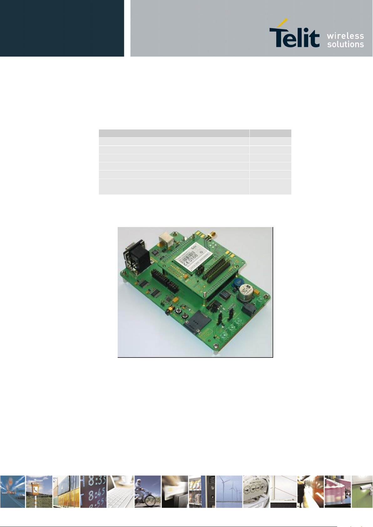
Figure 1: GE863-PY Interface Board (upper) fitted on EVK2 Motherboard (lower).
Reproduction forbidden without Telit Communications S.p.A. written authorization - All Rights Reserved page 17 of 243
Page 18
2.
Description
Telit EVK2 User Guide
1vv0300704 Rev.17 – 2013/05/30
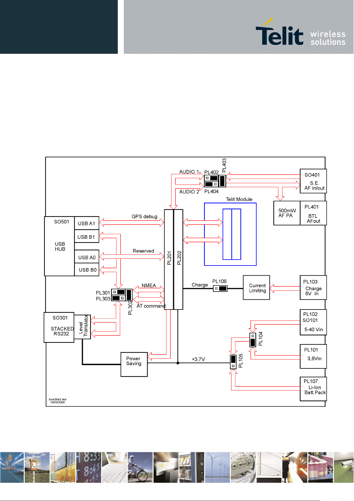
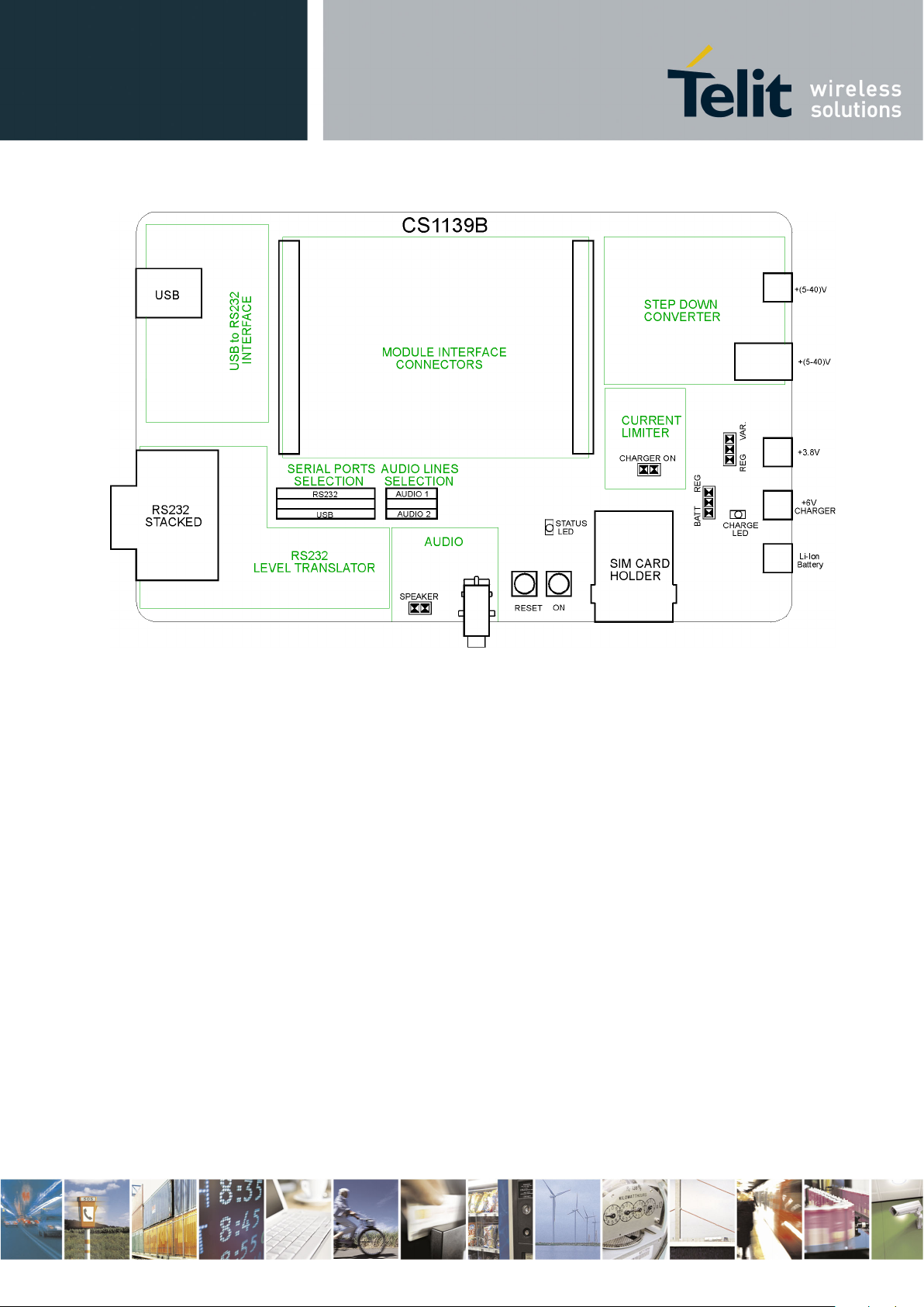
The motherboard CS1139B can be split into several functional blocks depending on the
implemented function; the following drawings show a block diagram and the displacement of
the main blocks on motherboard.
Figure 2: Miscellaneous signals, connections and routing on CS1139B.
Reproduction forbidden without Telit Communications S.p.A. written authorization - All Rights Reserved page 18 of 243
Page 19
2.1.
PCB characteristics
Telit EVK2 User Guide
1vv0300704 Rev.17 – 2013/05/30
Figure 3: CS1139B circuital displacement
Material: FR4
Thickness: 0, 95 mm
Surface finishing: Chemical gold plate Ni 5um/ Au 0,1um
Reproduction forbidden without Telit Communications S.p.A. written authorization - All Rights Reserved page 19 of 243
Page 20

2.2.
Mechanical characteristics of the assembled PCBs
2.2.1.
Mother Board CS1139B
2.2.2.
GM862 Interface CS1150B
2.2.3.
GE863 Interface CS1151A
2.2.4.
GE864 Interface CS1152B
2.2.5.
GE864-GPS Interface CS1439B
Telit EVK2 User Guide
1vv0300704 Rev.17 – 2013/05/30
Length 100 mm (max 102,6 mm)
Width 160 mm (max 166,10mm)
Height 47,6 mm (included the support with columns)
Weight 200 gr (without any interface)
Length 66,04 mm
Width 78,74 mm
Height 21,00 mm
Weight 27 gr (without the module)
Length 75 mm (max 84,70mm)
Width 78,74 mm
Height 21,00 mm
Weight 40 gr (with module)
Weight 44,3 gr (with module for GPS version)
Length 66,04 mm (max 75,20mm)
Width 78,74 mm
Height 21,00 mm
Weight 36 gr (with module)
Length 78.70 mm (max mm)
Width 83.70 mm
Height 21 mm
Reproduction forbidden without Telit Communications S.p.A. written authorization - All Rights Reserved page 20 of 243
Page 21

2.2.6.
GC864 Interface CS1203B
2.2.7.
GC864-C2 Interface CS1231X
2.2.8.
GE865 Interface CS1324A
2.2.9.
GE865/SE867-AGPS Interface CS1433
2.2.10.
GE865/JF2 Interface CS1521
2.2.11.
GL865 Interface CS1431A
2.2.12.
UC864-CC864 Interface KS0101C
Telit EVK2 User Guide
1vv0300704 Rev.17 – 2013/05/30
Length 66,04 mm
Width 78,74 mm
Height 21,00 mm
Weight 27 gr (without the module)
Length 50,00 mm
Width 33,00 mm
Height 5,60 mm
Weight 13,8 gr (with module)
Length 66,04 mm (max 75,20mm)
Width 78,74 mm
Height 21,00 mm
Weight 34 gr (with module)
Length 101.00 mm
Width 78.74 mm
Height mm
Length 101,00 mm
Width 78,74 mm
Height mm
Length 66,04 mm (max 75,20mm)
Width 78,74 mm
Height 21,00 mm
Weight 34 gr (with module)
Length 102,00 mm
Reproduction forbidden without Telit Communications S.p.A. written authorization - All Rights Reserved page 21 of 243
Page 22

2.2.13.
HE910 Interface CS1467C
2.2.14.
UE910 Interface CS1467D
2.2.15.
GE910 Interface CS1467D
2.2.16.
GE910-GNSS Interface CS1467F
2.2.17.
GE910-QUAD V3 Interface CS1467F
2.2.18.
DE910 Interface CS1467D
2.2.19.
CE910 Interface CS1467D
Telit EVK2 User Guide
1vv0300704 Rev.17 – 2013/05/30
Width 67,50 mm
Height 20,80 mm
Weight 55 gr (without module)
Length 107,00 mm
Width 102,00 mm
Height 25,00 mm
Length 107,00 mm
Width 102,00 mm
Height 25,00 mm
Length 107,00 mm
Width 102,00 mm
Height 25,00 mm
Length 107,00 mm
Width 102,00 mm
Height 25,00 mm
Length 107,00 mm
Width 102,00 mm
Height 25,00 mm
Length 107,00 mm
Width 102,00 mm
Height 25,00 mm
Length 107,00 mm
Width 102,00 mm
Height 25,00 mm
Reproduction forbidden without Telit Communications S.p.A. written authorization - All Rights Reserved page 22 of 243
Page 23
2.2.20.
GL865 V3 Interface CS1531B
2.2.21.
LE920 Interface KS0145B
NOTE:
Telit EVK2 User Guide
1vv0300704 Rev.17 – 2013/05/30
Length 92,00 mm
Width 89,00 mm
Height 25,00 mm
Length 92,00 mm
Width 107,00 mm
Height 25,00 mm
The overall height for every combination (mother board + interface board) is still the
height of the mother board
Reproduction forbidden without Telit Communications S.p.A. written authorization - All Rights Reserved page 23 of 243
Page 24

3.
Startup procedure
NOTE:
Telit EVK2 User Guide
1vv0300704 Rev.17 – 2013/05/30
The motherboard factory setup is:
Serial port RS232
DC source + (5÷40) V / ≥ 1A
Batt.Charger connector (PL106) On
RX Amplifier Audio 1
Respect the following order to use the EVK2:
• insert your SIM card
• set properly all jumpers in the desired position
• plug the module Interface board into PL201 and PL202
• connect the antenna to RF connector (on module or on Interface Board)
• connect the audio accessories if required
• plug the external power supply into the right socket, depending from DC source
• switch ON the power supply
• connect the serial cable between your PC and UART (RS232 or USB 1.1)
• push ON/OFF button on EVK Board for at least 5 seconds, on the XX910 form factor
products, push ON/OFF button on Interface Board for at least 5 seconds until the
STATUS LED is on
Your EVK2 should now be operational and ready to receive AT Commands.
When you use USB port, it is very important to respect the following sequences:
Start: first turning ON the EVK2 and then connecting it to the PC
Stop: first disconnecting the PC and then turning OFF the EVK2
Reproduction forbidden without Telit Communications S.p.A. written authorization - All Rights Reserved page 24 of 243
Page 25
4.
Insertion of the Interface Boards
Telit EVK2 User Guide
1vv0300704 Rev.17 – 2013/05/30
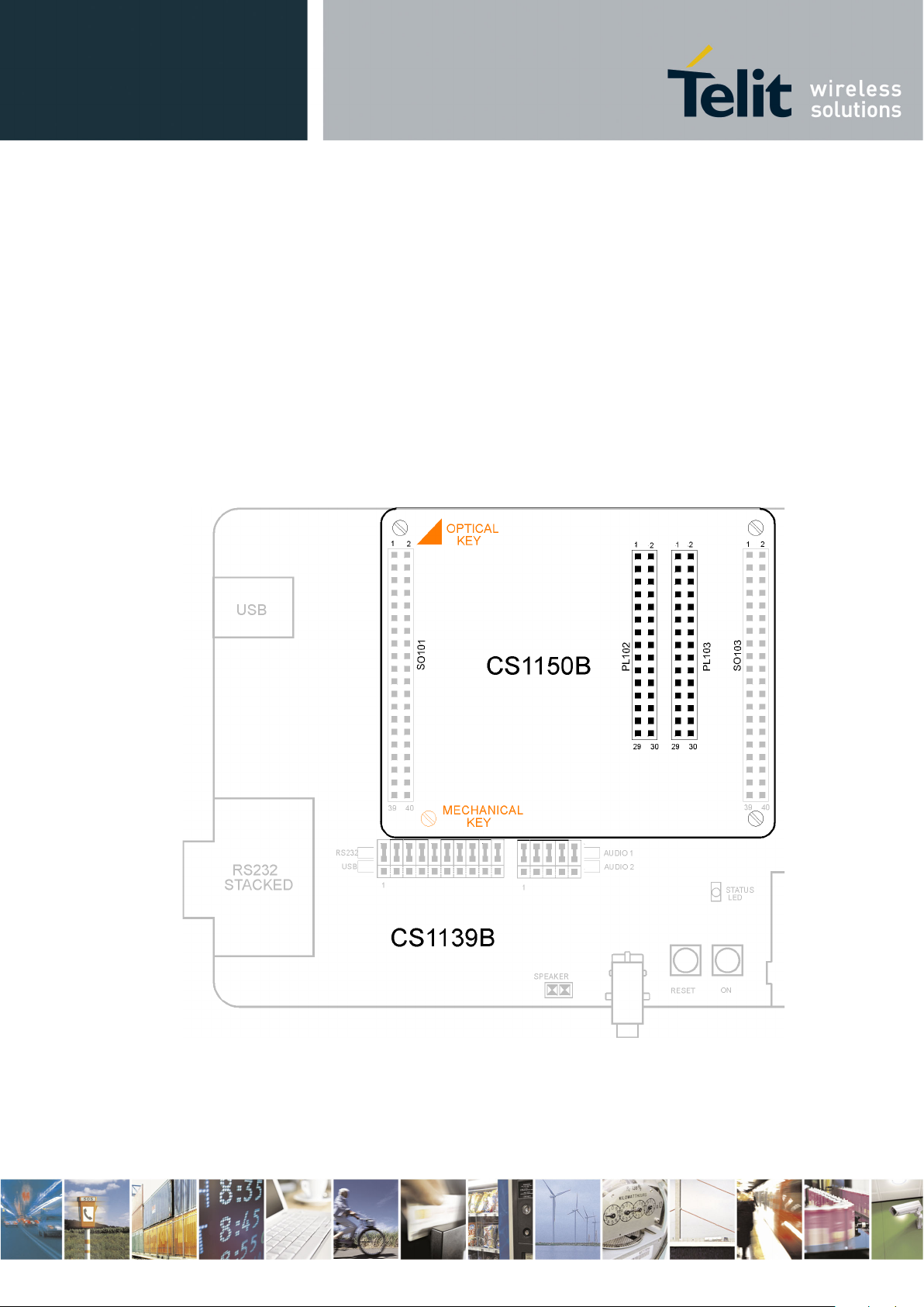
Every Interface Board must be inserted on CS1139B paying great attention to match the
position of the main connectors; this has been made easy:
optically by a triangle drawn on both printed circuits (except CS1231X) ;
mechanically shifting a column out of regular square cross position.
Both guide systems are highlighted by orange color as shown on the next figure.
Figure 4: Positioning Guide Systems of GM862 Interface Board on CS1139B.
Reproduction forbidden without Telit Communications S.p.A. written authorization - All Rights Reserved page 25 of 243
Page 26
5.
Power supply setting
5.1.
Fixed DC source
Telit EVK2 User Guide
1vv0300704 Rev.17 – 2013/05/30
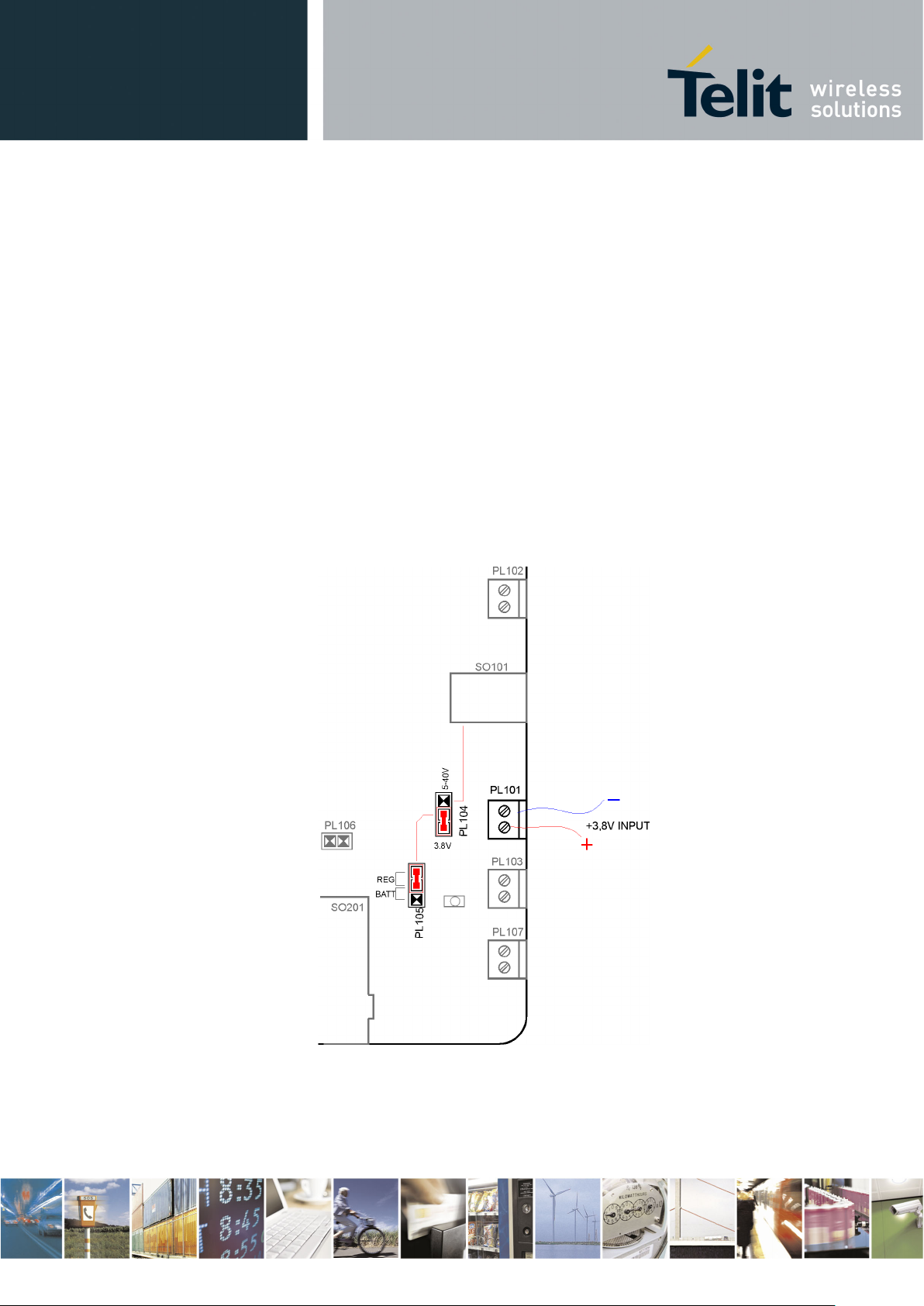
The EVK2 could be powered by different external sources, only one at time. The requested
setting is made inserting the proper jumper connectors in the right position as described in the
following paragraphs.
Be careful to the connections, even if every supply line is protected by a diode against “polarity
reversing” and by a 0Ω resistor against “short circuiting”.
Connect a +3,8V / ≥ 2A fixed DC source to PL101 respecting the polarization; short pin2 &
pin3 – PL104 and pin1 & pin2- PL105 by 2 contacts jumper connectors. No other jumpers
are needed.
Figure 5: +3,8V fixed source setting
Reproduction forbidden without Telit Communications S.p.A. written authorization - All Rights Reserved page 26 of 243
Page 27
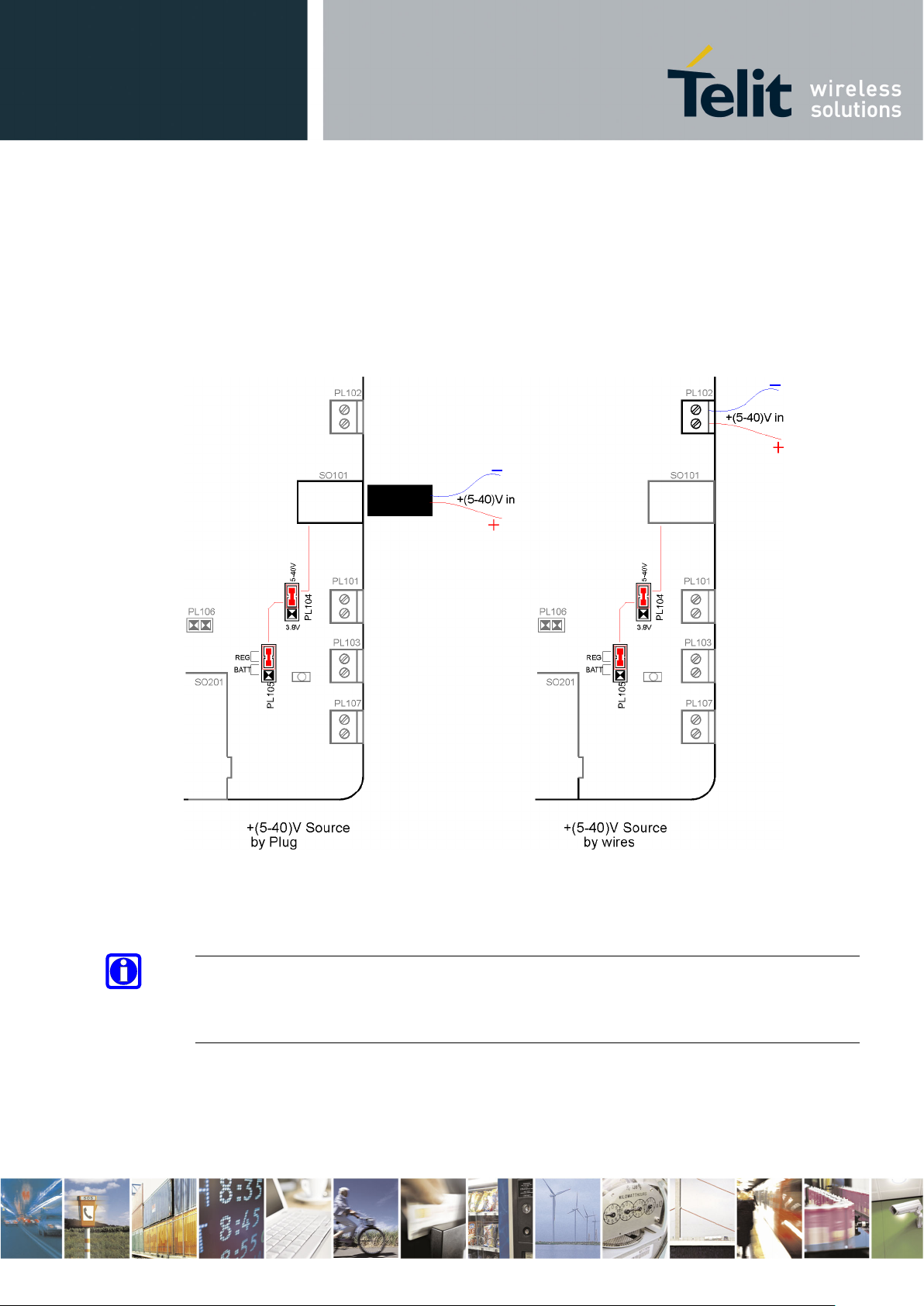
5.2.
Variable DC source
NOTE:
Telit EVK2 User Guide
1vv0300704 Rev.17 – 2013/05/30
Connect a + 5÷40 V / ≥ 1A variable DC source to PL102 (by wires) or to SO101 (by coaxial
plug), with care to the polarities. Short pin1& pin2-PL104 and pin1& pin2-PL105 by
inserting 2 contacts jumper connectors.
No other jumpers are needed.
Figure 6: Variable DC source setting
It is useful set the variable DC source at 6V minimum to avoid problems with voltage
drops due to the length of the wires or the conductors gauge.
Reproduction forbidden without Telit Communications S.p.A. written authorization - All Rights Reserved page 27 of 243
Page 28
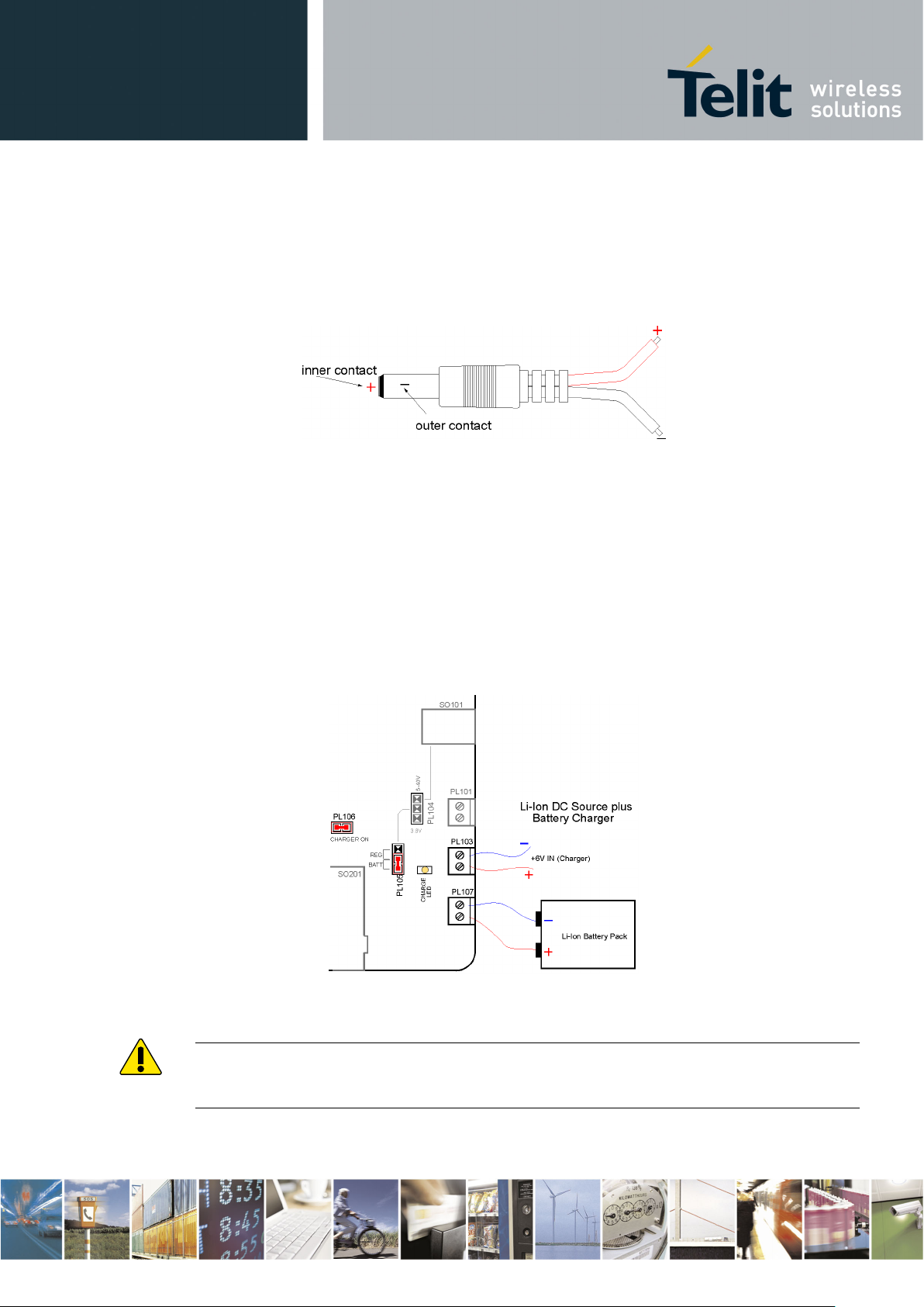
5.2.1.
Coaxial Plug
5.3.
Li-Ion Battery pack and Charger
WARNING:
NEVER CONNECT
Telit EVK2 User Guide
1vv0300704 Rev.17 – 2013/05/30
The figure 7 shows the connections of the Power Plug of left part of figure 6.
Figure 7: Coaxial “Power Plug” connection.
Connect a Li-Ion battery pack to PL107 with care to the polarity then short pin 2& pin3PL105 by inserting the 2 contacts jumper connector.
If the battery pack needs to be recharged, connect a +6V /≥ 0,5A fixed DC source to PL103,
with care to the polarity; short PL106 inserting a 2 contacts jumper connector as shown in
figure 8: the yellow CHARGE LED will be on during the initial phase of charge. If you
remove the battery pack when the charge stops (no current flows), immediately REMOVE
also the jumper of PL106.
Figure 8: Battery Pack and Battery Charger wired connections and setting.
Reproduction forbidden without Telit Communications S.p.A. written authorization - All Rights Reserved page 28 of 243
any Battery Charging source to PL102 without connected Battery!!
Page 29

5.4.
Application Notes
5.4.1.
Li-Ion Battery Pack
5.4.2.
About Current Charger
where
R
par
Vbe
Q
I
ch
→=
102
R113R112,R111,//R110,
R
par
=
WARNING:
SET THE MAXIMUM VOLTAGE
CURRENT UNLIMITED SOUCE
Telit EVK2 User Guide
1vv0300704 Rev.17 – 2013/05/30
The 3.7V Li-Ion rechargeable Battery Pack should be connected directly to PL107 connector.
Remember to use the connection cables as short as possible, with the appropriate conductors
gauge and the other attributes, such as device power budget and cable flexibility, in order to
match the specified voltage drop (especially during the high current absorption periods).
To obtain the best performance we suggest a capacity of 1000 mAh (
not lower than 500 mAh).
With a +6V Current Unlimited Source connected to PL103 connector, the battery pack will
be directly charged through VBATT connector pins of the Telit Modules, under control of the
Internal Charge Algorithm (only on models where is implemented).
Depending of the size, the Li-Ion cell manufacturers suggest a charge current value not
greater than 1,5C
current means a longer charging time, a current equal to 0,5C is considered to be a good
choice.
With reference to the schematic diagram 30276SE11139A –sheet1, the Current Limiting
Circuit (
of the Charge Current in respect to the law:
Q102, Q103, R106, R107, R108, R109, R110, R111, R112, R113, C105) sets the maximum value
(C= Capacity of the battery pack, expressed in mAh); even if a lower
With the default values, the charge current will be ∼ 470mA, which will charge Battery
Packs with a capacity from 350mAh to 1000mAh, without any dissipation problem.
If a higher capacity Battery Pack is needed, you must increment the Time Out in the Telit
Modules.
of the
lower then +8V.
Reproduction forbidden without Telit Communications S.p.A. written authorization - All Rights Reserved page 29 of 243
Page 30
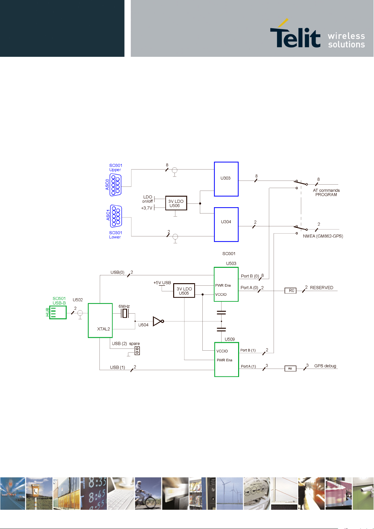
6.
Serial interface
The following figure shows the architecture of the serial ports.
Telit EVK2 User Guide
1vv0300704 Rev.17 – 2013/05/30
Figure 9: Serial ports block diagram.
Reproduction forbidden without Telit Communications S.p.A. written authorization - All Rights Reserved page 30 of 243
Page 31

6.1.
Serial Port Setup
Telit EVK2 User Guide
1vv0300704 Rev.17 – 2013/05/30
Communications between your application and the Telit modules are allowed connecting the
DTE to the Asynchronous Serial Interfaces of Base-Band Chip, ASC0 and ASC1, through
the stacked standard RS232 communications port (double 9 way D-socket connector at slow
data rates of RS232 protocol) or a standard USB-B Series receptacle (at higher data rates of
USB1.1 specification through a CMOS HUB that realizes a multiple attachment point
device).
Figure 10: Double 9 way D-Socket Connector
The selection is made short circuiting PL302&PL303 (RS232 mode) or PL302&PL301
(USB 1.1 mode) by 10 pieces of 2 contacts jumpers. This solution has been implemented
because you can isolate every single line during the development.
Figure 11: Serial Ports selection
Reproduction forbidden without Telit Communications S.p.A. written authorization - All Rights Reserved page 31 of 243
Page 32

7.
Audio Section
7.1.
Overview
7.1.1.
History
Telit EVK2 User Guide
1vv0300704 Rev.17 – 2013/05/30
The Base Band chip of the Telit’s modules provides one or two (depends of model) audio
paths both in receive and in transmit sections, which could be active only one at time.
To turn on your well-suited section on EVK2, please refer to “AF Amplifiers Setting
“paragraph and followings.
To know which are the suggested performances of the EVK2 audio transducers, refer to
“Audio Accessories “paragraph.
The Baseband chip of our modules was developed for the cellular phones, which needed two
separated amplifiers both in RX and in TX section. A couple of amplifiers had to be used
with internal audio transducers (
be used with external audio transducers (
Transducers definitions:
Headsets are transducers that receive an electrical signal from a receiver and use speakers
placed in close proximity to the ears to convert the signal into audible sound waves.
In the context of telecommunication, the word Headset is also commonly understood to refer
to a combination of Headphone and Microphone used for two-way communication, like with
a mobile phone.
Earphones are small Headphones that are placed directly outside of the ear canal, but
without fully enveloping it. They are generally inexpensive and are favored for their
portability and convenience.
Earpiece A part whether of a telephone receiver or hearing aid, that fits in or is held next to
the ear.
Handset mode, HS) while the other couple of amplifiers must
Handsfree mode, HF).
Reproduction forbidden without Telit Communications S.p.A. written authorization - All Rights Reserved page 32 of 243
Page 33

7.2.
Actual
7.2.1.
The choice
7.3.
Differential and Single Ended
7.3.1.
Concepts
Telit EVK2 User Guide
1vv0300704 Rev.17 – 2013/05/30
The HS and HF definitions have been kept in the Software and on the schematics of the Telit
modules, but with EVK2 we will refer to Audio1 and Audio2 section instead of Handset and
Handsfree respectively, remembering that:
they can have fully equivalent electrical performances (like the two microphone amplifiers)
they can activate the same functionalities (like the Echo Canceller module)
they can offer slightly different performances (like the two speaker buffering stages)
The activation of the audio path is made Hardware by AXE line or Software by AT#CAP
command.
If you don’t have any load driving constraint (like a speaker with an impedance coil lower
than 16 ohm), the choice between one or other “block” could be done without consideration
related to the electrical performances; for example in order to overcome the PCB design
difficulties.
Any voltage can be characterized by a potential difference between two terminals.
The configuration of the two terminals and how the signal is delivered from output to input
allows the signal to be more generally described in one of three ways:
Single-ended signal
One terminal for a single-ended connection is always at fixed potential (
Ground
Differential Signals
signal pair, neither of the terminals is Ground.
Common mode Signals. They represent a special case of differential signals, also
travelling between a pair of traces, where the voltage potential on both signals is
the same.
).
. This is a signal delivered between a signal trace and a ground.
usually
. These are signals that travel through a pair of traces. On the
Reproduction forbidden without Telit Communications S.p.A. written authorization - All Rights Reserved page 33 of 243
Page 34

7.3.2.
Benefits and disadvantages
Telit EVK2 User Guide
1vv0300704 Rev.17 – 2013/05/30
Differential amplifiers are desirable to use, especially in audio applications where signal
levels are very low such as those from microphones.
Classically, the benefits obtained from differential amplification are:
Increase of Common Mode Rejection Ratio (CMRR)
Differential inputs enable cancellation of any noise common on both inputs. Noise
generated at the input of the amplifier has a greater effect than noise generated at
the output, because any noise on the input is multiplied by the gain of the amplifier.
Increase Signal to Noise Ratio (SNR)
The inputs to the amplifier are especially sensitive to noise because they are
typically not driven by a very low impedance source.
High Rejection in Electromagnetic Interference (EMI)
Noise immunity is very important in wireless phones because the RF signal is sent
in bursts such that the frequency between bursts is in the audio band. RF
rectification is such a problem that many manufacturers shield the audio portion of
the phone.
Double Useful signals level
The signal levels from microphone and the voltage swing to the load are doubled.
Then the AF power to the load it is 4 times the single-ended Afpower at the same
voltage supply.
No output blocking capacitor is needed
Even if the differential outputs are biased at half-supply; no DC voltage exists
across the load. You do not need the big, expensive and heavy blocking capacitors
generally from 33 µF to 1000 µF), lowering the cost and saving PCB space
(
There is no frequency limiting effect due to the high pass filter network created with
the speaker impedance and the coupling capacitance.
Less shielding is required from amplifier to load
Mainly we have only one disadvantage using differential amplification: the routing of one
more signal line could be more difficult and the additional trace requires more board space.
Reproduction forbidden without Telit Communications S.p.A. written authorization - All Rights Reserved page 34 of 243
Page 35

7.3.3.
Settings
Telit EVK2 User Guide
1vv0300704 Rev.17 – 2013/05/30
Connecting your accessories to SO401 in/out connector, you will implement Single Ended
Input/Output configurations.
Removing all 2 contacts jumpers inserted between PL402&PL403 or PL403&PL404, the
in/out lines of our modules will be directly available on PL402 and PL404 connectors.
In such a way, you will be able to implement fully Differential Input/Output configurations.
Only with GC864-QUAD/PY-C2 modules the Ear output lines are AC coupled.
Figure 12: PL402 and PL404 Fully Differential audio lines.
Reproduction forbidden without Telit Communications S.p.A. written authorization - All Rights Reserved page 35 of 243
Page 36

8.
AF Amplifiers Setting
Telit EVK2 User Guide
1vv0300704 Rev.17 – 2013/05/30
The Base Band Processor Audio Amplifiers selection is made short-circuiting PL403&PL402
(RX Amplifier 1) or PL403&PL404 (RX Amplifier 2). In such a way you could verify the
complete performance of both audio paths.
Figure 13: Base Band Audio Amplifiers selection
Reproduction forbidden without Telit Communications S.p.A. written authorization - All Rights Reserved page 36 of 243
Page 37

9.
Audio outputs
9.1.
Low AF Power Mode
NOTE:
Telit EVK2 User Guide
1vv0300704 Rev.17 – 2013/05/30
The EVK2 output audio signals could be drive a device connected to SO401 (LOW AF POWER
mode) or to PL401 (HIGH AF POWER mode).
Inserting the 2 contacts jumpers as explained at paragraph 9A, a standard off-the-shelf
Headset should be connected to the SO401 (
With such an insertion, the Telit Modules will power the Microphone through a Single
Ended input circuit and the Earpiece through a Single Ended/ AC coupled output circuit.
3 contacts, 2.5mm diameter jack connector).
The acoustic performance of the
depends by its housing, fitting and acoustic impedance.
The coil impedance of the Headset should be higher than 15 ohm @ 1KHz.
Headset (frequency response, loudness
) largely
Figure 14: Headset insertion Figure 15: Headset plug connection
Reproduction forbidden without Telit Communications S.p.A. written authorization - All Rights Reserved page 37 of 243
Page 38

9.2.
High AF Power Mode
410
407
2
406
404
2
R
R
R
R
A
v
•=•=
NOTE:
Telit EVK2 User Guide
1vv0300704 Rev.17 – 2013/05/30
Connecting an 8 ohm Speaker to PL401 by a 2 contacts female connector, you could drive it
through the 500mW Power Amplifier.
In this case the Speaker will be driven in fully differential configuration, with no side
connected to ground and without any output coupling capacitor. Therefore care must be
taken because there is DC voltage on both sides of the Speaker.
The overall gain of this amplifier can be modified varying the ratios R406/R404 and
R407/R410:
if R404=R407 and R406=R410
The coil impedance of the Speaker should be higher than 8 ohm @ 1KHz .
Figure 16: Speaker insertion
Reproduction forbidden without Telit Communications S.p.A. written authorization - All Rights Reserved page 38 of 243
Page 39

9.2.1.
Speaker and Stand-alone Microphone
Telit EVK2 User Guide
1vv0300704 Rev.17 – 2013/05/30
If you are using a Speaker, you can connect a stand-alone electrete microphone by a coaxial
2,5mm plug to SO401, respecting the following pin-out.
Figure 17: Microphone Plug Connection
Figure 18: Speaker & Microphone case insertion
Reproduction forbidden without Telit Communications S.p.A. written authorization - All Rights Reserved page 39 of 243
Page 40

9.2.2.
Speaker plus Headset
WARNING:
must be at least 16Ω@1KHz
or
higher.
must be at least 8Ω@1KHz
or
higher
Telit EVK2 User Guide
1vv0300704 Rev.17 – 2013/05/30
If you have chosen to connect the Speaker to HIGH AF POWER output, without having a
stand-alone electret microphone, it is also possible to connect a standard off-the-shelf
Headset to SO401 without any problem, as shown in the figure 18: the AF output signal will
be heard on both Speaker and Earpiece.
You must use the right coil impedance depending from audio output you want to use.
If you sort out the LOW AF POWER solution connecting your Headset to SO401, the coil
impedance
If you sort out the HIGH AF POWER solution connecting your Speaker to PL401, the coil
impedance
Figure 19: Speaker plus Headset insertion
Reproduction forbidden without Telit Communications S.p.A. written authorization - All Rights Reserved page 40 of 243
Page 41

10.
Audio Accessories
10.1.
Headset
Nominal sensitivity
-45dBV
rms
/1Pa (+/- 3dB)
Line coupling
AC
Nominal Voltage
2V
Range of Using Voltage
(1÷10)V
Consumption Current
(150÷500 ) μA
Impedance
2,2KΩ
Signal to Noise Ratio
56dB /1KHz/1Pa (A curve)
Inner EMI capacitor between
terminals
10pF, 33pF
Rated Input Power
5mW
Maximum Input Power
20mW
Coil Impedance
32Ω ± 5Ω @ 1kHz
SPL
95±3 dB @ 1KHz/1mW sine
wave
Resonance frequency (Fo)
< 350Hz
Useful Bandwidth
Fo ÷ 8000 Hz @ -3dB
Telit EVK2 User Guide
1vv0300704 Rev.17 – 2013/05/30
The following tables show the suggested specification to obtain the best performance from offthe-shelf accessories.
Table 2: Microphone electrical characteristics
Table 3: Earpiece electrical characteristics
Reproduction forbidden without Telit Communications S.p.A. written authorization - All Rights Reserved page 41 of 243
Page 42

10.2.
Stand-alone microphone
Nominal sensitivity
-45dBV
rms
/1Pa (+/- 3dB)
Line coupling
AC
Nominal Voltage
2V
Range of Using Voltage
(1÷10)V
Consumption Current
(150÷500 ) μA
Impedance
2,2KΩ
Signal to Noise Ratio
56dB /1KHz/1Pa /A curve
EMI capacitor between terminals
10pF, 33pF
10.3.
Speaker
Rated Input Power
500 mW
Maximum Input Power
1W
Coil Impedance
≥ 8Ω
SPL
≥ 85±3 dB @ 1KHz
Resonance frequency (Fo)
< 350Hz
Useful Bandwidth
Fo ÷ 8000 Hz @ -3dB
Telit EVK2 User Guide
1vv0300704 Rev.17 – 2013/05/30
Table 4: Microphone electrical characteristics
Table 5: Speaker electrical characteristics
Reproduction forbidden without Telit Communications S.p.A. written authorization - All Rights Reserved page 42 of 243
Page 43

11.
Indication and services
11.1.
Optical Indicators
11.1.1.
Status Led
LED status
Device Status
Permanently off
Device off
Fast blinking (period 1s, Ton 0,5s)
Net search / Not registered / turning off
Slow blinking (period 3s, Ton 0,3s)
Registered: full service
Permanently on
A call is active
Telit EVK2 User Guide
1vv0300704 Rev.17 – 2013/05/30
It is a debug aid that shows information on the network service availability and Call status.
Table 6: STAT_LED indications
Reproduction forbidden without Telit Communications S.p.A. written authorization - All Rights Reserved page 43 of 243
Figure 20: STAT_LED position
Page 44

11.1.2.
CHARGE Led
A yellow LED is used as Charge In Act Indicator, as explained in the following table.
CHARGE LED Meaning
Always on Start Charge/ Hugh current Charge in act
Always off Low current Charge in act/Charge stop
Telit EVK2 User Guide
1vv0300704 Rev.17 – 2013/05/30
Table 7: CHARGE LED indications
Figure 21: CHARGE LED position
Reproduction forbidden without Telit Communications S.p.A. written authorization - All Rights Reserved page 44 of 243
Page 45

11.2.
Switches
11.2.1.
POWER ON Switch
11.2.2.
RESET Switch
Telit EVK2 User Guide
1vv0300704 Rev.17 – 2013/05/30
You turn On/Off or Reset the EVK2 by 2 push buttons.
Push ON/OFF button on EVK Board for at least 5 seconds, on the XX910 form factor
products, push ON/OFF button on Interface Board for at least 5 seconds until the STATUS
LED starts to slowly blink (
Whenever the RESET SWITCH is pressed, you could reset the Telit module in use.
When the device is reset, it stops any operation without doing any detach operation from the
network where it is registered and it reboots after the release of the Reset Switch.
This behavior is not a proper shut down because any GSM device is requested to issue a
detach request at turning off. For this reason the Reset pressing action must not be used to
normally reboot/shutting down the device, but only as an emergency exit in the rare case the
device remains stuck waiting for some network response.
The RESET is internally controlled at start-up to achieve always a proper power-on reset
sequence, so there is no need to control this pin on start-up. It may only be used to reset a
device already on that is not responding to any command.
ON state) or stops to blink (OFF state).
Figure 22: SWITCHES position
Reproduction forbidden without Telit Communications S.p.A. written authorization - All Rights Reserved page 45 of 243
Page 46

12.
Connectors pinout
12.1.
Motherboard to Module
Pin
Signal
Type
Function
1
NC1
2
TX_Trace
Digital Output
to RS232 or USB level translators
3
RX_Trace
Digital Input
from RS232 or USB level
translators
4
IIC_SDA_HW
Digital In/Out
from/to USB level translators
5
GND
DC voltage
Power
6
IIC_SCL_HW
Digital Input
from USB level translators
7
SSC0_CLK
Digital Output
to USB level translators
8
SSC0_MTSR
Digital In/Out
from/to USB level translators
9
SSC0_MRST
Digital In/Out
from/to USB level translators
10
NC
11
GND
DC voltage
Power
12
GND
DC voltage
Power
13
GND
DC voltage
Power
14
GND
DC voltage
Power
15
C109/DCD
Digital Output
to RS232 or USB level translator
16
C104/RXD
Digital Output
to RS232 or USB level translator
17
C103/TXD
Digital Input
from RS232 or USB level translator
18
C108/DTR
Digital Input
from RS232 or USB level translator
19
GND
DC voltage
Power
20
C107/DSR
Digital Output
to RS232 or USB level translator
21
C105/RTS
Digital Input
from RS232 or USB level translator
22
C106/CTS
Digital Output
to RS232 or USB level translator
23
C125/RING
Digital Output
to RS232 or USB level translator
24
NC
25
GND
DC voltage
Power
26
GND
DC voltage
Power
27
GND
DC voltage
Power
28
GND
DC voltage
Power
29
EAR_HF+
AC Out Voltage
Audio
30
EAR_MT-
AC Out Voltage
Audio
31
EAR_HF-
AC Out Voltage
Audio
Telit EVK2 User Guide
1vv0300704 Rev.17 – 2013/05/30
The connections between CS1139B and every Telit module Interface Board are made
through two 40 pin male connectors. Theirs pin functions are listed in the following tables.
1
DO NOT CONNECT
Reproduction forbidden without Telit Communications S.p.A. written authorization - All Rights Reserved page 46 of 243
Page 47

32
EAR_MT+
AC Out Voltage
Audio
33
AXE
DC voltage
INT/EXT Switching
34
MIC_HF-
AC In Voltage
Audio
35
MIC_MT+
AC In Voltage
Audio
36
MIC_HF+
AC In Voltage
Audio
37
MIC_MT-
AC In Voltage
Audio
38
GND
DC voltage
Power
39
GND
DC voltage
Power
40
GND
DC voltage
Power
Pin
Function
Type
NOTES
1
VBATT
DC voltage
Power
2
VBATT
DC voltage
Power
3
VBATT
DC voltage
Power
4
VBATT
DC voltage
Power
5
GND
DC voltage
Power
6
GND
DC voltage
Power
7
GND
DC voltage
Power
8
GND
DC voltage
Power
9
CHARGE
DC voltage
Power
10
CHARGE
DC voltage
Power
11
GND
DC voltage
Power
12
GND
DC voltage
Power
13
GND
DC voltage
Power
14
GND
DC voltage
Power
15
ON_OFF*
DC voltage
Pull up to VBATT
16
NC
17
RESET*
DC voltage
Module Reset
18
NC
19
NC
20
NC
21
STAT_LED
Open Collector
Status Indicator LED
22
NC
23
NC
24
NC
25
GND
DC voltage
Power
26
GND
DC voltage
Power
27
GND
DC voltage
Power
28
GND
DC voltage
Power
29
NC
30
NC
31
SIMIO
3V Only
SIM Data I/O
32
SIMCLK
Digital Signal
SIM Clock
33
SIMRST
DC voltage
SIM Reset
Telit EVK2 User Guide
1vv0300704 Rev.17 – 2013/05/30
Table 8: PL201-CS1139B
Reproduction forbidden without Telit Communications S.p.A. written authorization - All Rights Reserved page 47 of 243
Page 48

34
SIMVCC
DC voltage
SIM Power
35
SIMIN
DC voltage
SIM inside detector
36
NC
37
NC
38
GND
DC voltage
Power
39
GND
DC voltage
Power
40
GND
DC voltage
Power
Telit EVK2 User Guide
1vv0300704 Rev.17 – 2013/05/30
Table 9: PL202-CS1139B
Reproduction forbidden without Telit Communications S.p.A. written authorization - All Rights Reserved page 48 of 243
Page 49

13.
Module Interface Boards
13.1.
Generality
13.2.
Short Description
13.3.
Further Accessories for GPS version
SMA/MMCX cable adapter
Module under test
Interface Board
GPS Antenna
1ff1400073tlb
P/N
1rr0100071tlb
1
GM862-GPS
3990250670 1 -
GE863-GPS
3990250671
1
-
GE864-GPS
TBD 1 -
SE867-AGPS
TBD 1 -
HE910
3990250845
1
Telit EVK2 User Guide
1vv0300704 Rev.17 – 2013/05/30
You can use your EVK2 with see APPLICABILITY LIST Telit modules fitted on its own
Interface Board; all connections are made through 2x40 contacts connectors.
It’s possible to use these Interface Boards also in stand-alone mode, inserting the “not
mounted” components (related to RESET BUTTON, ON BUTTON, SIM HOLDER and
STATUS LED functions) plus the use of an external level translator circuit.
For more information refer to Telit Product Description.
The interface boards convert the module connection technology (board-to-board or BGA
soldering) into a PTH pin connector. The part of the basic interfaces is served by the
motherboard, whereas specific interfaces according to the type of the module (antenna,
general purpose inputs/outputs GPIO, ADC/DAC, UART) are available on the adapter board
to connect it to the user applications, extension boards, measurements equipment or other
tools.
When test the GPS products, besides the content of the single kits you need the accessories
listed in below table.
Reproduction forbidden without Telit Communications S.p.A. written authorization - All Rights Reserved page 49 of 243
Table 11. GPS versions further accessories.
Page 50

14.
GM862 Interface
14.1.
Stand-alone setup
Telit EVK2 User Guide
1vv0300704 Rev.17 – 2013/05/30
This board allows easily interfacing the module with the EVK2 and testing its functionalities;
any version of GM862 can be insert.
No settings are needed.
Figure 23: GM862 Interface Board
If you need to use the interface out of EVK2 (Stand-alone setup) you have to mount the
following missing components:
RESET Button
ON Button;
STATUS LED and its load resistance.
Reproduction forbidden without Telit Communications S.p.A. written authorization - All Rights Reserved page 50 of 243
Page 51

14.2.
Interface connectors
14.3.
Content of the kit
Description
Quantity
GM862 INTERFACE
1
ASSEMBLED CABLE L–250 RG174
TERMINALS SMA F & MMCX 90 M
Telit EVK2 User Guide
1vv0300704 Rev.17 – 2013/05/30
The following connectors are available:
2 male connectors (30 pins each one: PL102, PL103), on which it is possible to connect
external devices like user’s application, Telit extension boards, measurements equipment or
other tools
2 female connectors (40 pins each one: SO101, SO102), to connect the interface to the
EVK2 mother board circuits (power supply lines, serial in/out lines, audio in/out lines).
Please check out the contents of your interface kit; if any of the items is missing, please
contact your supplier.
1
Table 12.
Reproduction forbidden without Telit Communications S.p.A. written authorization - All Rights Reserved page 51 of 243
Page 52

15.
GE863 Interface
15.1.
Stand-alone setup
Telit EVK2 User Guide
1vv0300704 Rev.17 – 2013/05/30
This board allows easily interfacing the GE863 modules with the EVK2 and testing their
functionalities;
Figure 24: GE863 Interface Boards: GE863-QUAD or GE863-SIM (at left) and GE863-GPS (at right)
If you need to use the interface out of EVK2 (Stand-alone setup) you have to mount also:
the SIMCARD Holder;
the RESET Button
the ON Button;
the STATUS LED and its load resistance.
Reproduction forbidden without Telit Communications S.p.A. written authorization - All Rights Reserved page 52 of 243
Page 53

15.2.
Content of the kits
15.2.1.
GE863-PY/QUAD version
Description
Quantity
GE863 INTERFACE BOARD
1
2 PIN JUMPER FEMALE CONN
2
15.2.2.
GE863-GPS version
Description
Quantity
GE863–GPS INTERFACE BOARD
1
2 PIN JUMPER FEMALE CONN
2
15.2.3.
GE863-SIM version
Description
Quantity
GE863-SIM INTERFACE BOARD
1
2 PIN JUMPER FEMALE CONN
2
15.3.
Interface connectors
15.4.
Additional components for GPS version
Telit EVK2 User Guide
1vv0300704 Rev.17 – 2013/05/30
Please check out the contents of your interface kit; if any of the items is missing, please
contact your supplier.
Table 13
Table 14
Table 15
The following connectors are available in any version:
GSM RF connector (SMA Female)
2 male connectors (4 pins each one: PL101, PL102) to select the Serial port configuration
2 female connectors (40 pins each one: SO101, SO106) to connect the interface to the EVK2
mother board circuits (power supply lines, serial in/out lines, audio in/out lines)
2 male connectors (30 pins each one: PL103, PL104), on which it is possible to connect
external devices like user’s application, Telit extension boards, measurements equipment or
other tools
The following components are available only in GPS version (P/N 3990250671):
Reproduction forbidden without Telit Communications S.p.A. written authorization - All Rights Reserved page 53 of 243
Page 54

15.5.
USB connector
Telit EVK2 User Guide
1vv0300704 Rev.17 – 2013/05/30
GPS RF connector (SMA Female)
USB B-type connector and its circuitry (see schematic 30276SE11151A)
Figure 25: Connectors displacement on GE863-GPS
Reproduction forbidden without Telit Communications S.p.A. written authorization - All Rights Reserved page 54 of 243
The USB interface provides 2 serial ports that are related to the NMEA serial port and SIRF-
Binary serial port of GE863-GPS module.
It is possible to select if the SIRF Binary serial port will be available on the USB connector
or directly connected to the second serial port of the modem (CONTROLLED MODE).
For setting refer to paragraphs 16.7.1, 16.7.2.1, 16.7.2.2.
Page 55

15.6.
Serial port configuration
15.6.1.
GE863-PY/QUAD
Telit EVK2 User Guide
1vv0300704 Rev.17 – 2013/05/30
Figure 26: GE863-GPS Serial ports block diagram
To switch the serial lines you must short-circuit the PL101-PL102 connectors by 2 contacts
jumpers.
The 2 contacts jumpers have to be fitted between pin1&pin2 of PL101-PL102 connectors.
This carries out the Python Debug Port on Trace Port of EVK2.
Reproduction forbidden without Telit Communications S.p.A. written authorization - All Rights Reserved page 55 of 243
Page 56

15.6.2.
GE863 – GPS
NOTE:
Telit EVK2 User Guide
1vv0300704 Rev.17 – 2013/05/30
Figure 27: Jumpers setting for GE863-PY/QUAD
The 2 contacts jumpers have to be fitted between pin2&pin3 or pin3&pin4 of PL101-PL102
connectors.
“CONTROLLED MODE”
This set the SIRF Binary to serial port of the modem. (Typical application Design)
Figure 28: Jumpers setting for SIRF BINARY port connected to MODEM port 2
All AT GPS commands
are available in this configuration
Reproduction forbidden without Telit Communications S.p.A. written authorization - All Rights Reserved page 56 of 243
Page 57

15.7.
ANTENNA connectors
15.7.1.
GPS ANTENNA connector
WARNING:
15.7.2.
GSM ANTENNA connector
15.7.3.
RFU ANTENNA connector
Telit EVK2 User Guide
1vv0300704 Rev.17 – 2013/05/30
“SEPARATED SERIAL PORT”
This set the SIRF Binary available on the USB connector.
Figure 29: Jumpers setting for SIRF BINARY port available on USB connector
NOTE:
In this configuration soma AT GPS commands are not available. Refer to AT Commands
Reference User Guide.
An active GPS antenna should be connected to SO104; the GPS section provides the DC
feeding.
Don’t connect a
A GSM antenna should be connected to SO103.
GSM
antenna on this connector
Reproduction forbidden without Telit Communications S.p.A. written authorization - All Rights Reserved page 57 of 243
On PCB there is the mounting possibility of a further RF connector (SO105): it is related to
future implementation.
Page 58

16.
GE864 Interface
16.1.
Stand-alone setup
Telit EVK2 User Guide
1vv0300704 Rev.17 – 2013/05/30
This board allows easily interfacing the GE864 modules with the EVK2 and testing their
functionalities.
No settings are needed.
Figure 30: GE864 Interface Board
If you need to use the interface out of EVK2 (Stand-alone setup) you have to mount the
following missing components:
• the SIMCARD Holder;
• the RESET Button
• the ON Button;
• the STATUS LED and its load resistance.
Reproduction forbidden without Telit Communications S.p.A. written authorization - All Rights Reserved page 58 of 243
Page 59

16.2.
Interface connectors
16.3.
Content of the kit
Description
Quantity
GE864 INTERFACE
1
Telit EVK2 User Guide
1vv0300704 Rev.17 – 2013/05/30
The following connectors are available:
2 male connectors (30 PTH pins each one: PL102, PL103), by which it is possible to
connect external devices, user’s application, Telit extension boards, measurements
equipment or other tools;
2 female connectors (40 PTH pins each one: SO101, SO102), to connect the interface to the
EVK2 mother board circuits (power supply lines, serial in/out lines, audio in/out lines);
Please check out the contents of your interface kit; if any of the items is missing, please
contact your supplier.
Table 16
Reproduction forbidden without Telit Communications S.p.A. written authorization - All Rights Reserved page 59 of 243
Page 60

17.
GE864-GPS Interface
17.1.
Part numbering
Part number
Identifier
Module mounted
3990250820
cs1439b
cs1479
3990250821
cs1439b-A
cs1446
3990250822
cs1439b-B
cs1485a
Telit EVK2 User Guide
1vv0300704 Rev.17 – 2013/05/30
This board allows testing the functionalities and performance of the GE864-GPS module.
Figure 31: GE864-GPS Interface Board
This board comes in three different configurations, each characterized by its own part
number, depending on the module it contains. In the following paragraphs we will refer to
them using an identifier according to the table below:
Table 17
Reproduction forbidden without Telit Communications S.p.A. written authorization - All Rights Reserved page 60 of 243
Page 61

17.2.
Stand-alone setup
17.3.
Interface connectors
17.4.
Contents of the kit
Description
Quantity
GE864-GPS INTERFACE
1
JUMPERS
13
Telit EVK2 User Guide
1vv0300704 Rev.17 – 2013/05/30
The interface can be used without the EVK2, in this case the following components have to
be soldered on the board:
the GSM-RESET button
the GSM-ON button
the STATUS led and its load resistor.
The following connectors are available:
2 male connectors (30 PTH pins each: PL101 and PL102), to connect external devices,
user’s applications, Telit extension boards, measurement equipment or other tools; PL102
can also be used to select particular configurations between the GSM module’s GPIOs and
the GPS module
2 female connectors (40 PTH pins each one: SO101 and SO104), to connect the interface to
the EVK2 mother board (power supply lines, serial in/out lines, audio in/out lines)
1 male connector (3 PTH pins: PL104), to select an enable signal for the external GPS LNA
1 male connector (2 PTH pins: PL105), in order to allow inserting an ammeter in series
with the supply, in order to monitor the module’s current consumption
1 GSM RF connector (SMA Female: SO105)
1 GPS RF connector (SMA Female: SO103)
1 JTAG connector (PL103, not mounted)
1 male connector (12 PTH pins: PL201), to select one of the available configurations for the
Serial and USB ports.
Please check out the contents of your interface kit. If any of the following items is missing,
contact your Telit supplier.
Table 18
Reproduction forbidden without Telit Communications S.p.A. written authorization - All Rights Reserved page 61 of 243
Page 62

17.5.
Power supply
17.6.
GPS external LNA enable signal
Telit EVK2 User Guide
1vv0300704 Rev.17 – 2013/05/30
The module (but not the whole interface) receives its power supply from PL105: this jumper
must always be plugged in, except when a series measurement instrument is needed.
Figure 32: Jumper for VBATT.
The module contains an internal LNA for the GPS antenna that is enabled by default. The
user can though decide to use an external LNA: this option is selected by means of a
software command, which puts the internal LNA in a low gain mode and provides an
additional signal to enable the external LNA. The interface can provide a bias for the
external LNA, and the user can choose whether to enable it by this signal or to leave it
always enabled, by means of a jumper on PL104, as shown in the picture below.
Reproduction forbidden without Telit Communications S.p.A. written authorization - All Rights Reserved page 62 of 243
Page 63

17.7.
Serial port configuration
Telit EVK2 User Guide
1vv0300704 Rev.17 – 2013/05/30
Figure 33: Jumper on PL104.
By means of proper jumper connections on PL201, three different configurations for serial
outputs can be selected. These configurations are mutually exclusive.
Figure 34: GE864-GPS Interface Board serial connections
Reproduction forbidden without Telit Communications S.p.A. written authorization - All Rights Reserved page 63 of 243
Page 64

17.7.1.
ASC1 to RS-232
17.7.2.
GPS to ASC1 (internal host controlling configuration)
Telit EVK2 User Guide
1vv0300704 Rev.17 – 2013/05/30
This configuration connects the ASC1 UART to the Trace serial connector of the EVK2.
Figure 35: ASC1 to RS-232 (Trace) configuration
This configuration directly connects the host GSM module to the GPS receiver, thus setting
the GPS receiver in Controlled Mode.
Figure 36: GPS to ASC1 configuration
Reproduction forbidden without Telit Communications S.p.A. written authorization - All Rights Reserved page 64 of 243
Page 65

WARNING:
17.7.3.
GPS to RS-232 (external host controlling configuration)
17.7.4.
GPS to USB
Telit EVK2 User Guide
1vv0300704 Rev.17 – 2013/05/30
Other than the ASCII UART, the user must also connect the host module’s GPIOs to the
corresponding signals of the GPS receiver (as explained in the next paragraphs).
This configuration allows sending the GPS output to the Trace serial connector of the EVK2.
Figure 37: GPS to RS-232 (Trace) configuration
The NMEA sentences can be redirected to EVK2’s USB port by setting PL201 as explained
in the Figure 37, i.e. connecting the NMEA line with the RS-232, and at the same time
setting the EVK2 serial line on USB Mode, as shown in Paragraph 7.1 of this document.
Reproduction forbidden without Telit Communications S.p.A. written authorization - All Rights Reserved page 65 of 243
Page 66

17.8.
GPIO settings
17.8.1.
Internal host controlling configuration
Telit EVK2 User Guide
1vv0300704 Rev.17 – 2013/05/30
The interface allows choosing among different options for driving the GPS control signals:
Using the GPIOs of the GSM module
Using an external host
Manually controlling the signals by plugging a jumper.
The last option is not available for every signal and every configuration; please refer to the
schematics of the interface for more details.
The choice among the options can be made by PL102, as detailed below.
The following settings on PL101 and PL102 allow selecting the internal host configuration.
Two different cases have to be considered:
cs1439b-A
cs1439b and cs1439b-B
Refer to the beginning of this chapter for the correspondence between board part number
and mounting options.
Figure 38: Settings for PL101 and PL102: internal host,cs1439b-A
Reproduction forbidden without Telit Communications S.p.A. written authorization - All Rights Reserved page 66 of 243
Page 67

17.8.2.
External host controlling configuration
Telit EVK2 User Guide
1vv0300704 Rev.17 – 2013/05/30
Figure 39: Settings for PL101 and PL102: internal host, cs1439b and cs1439b-B
Note that jumper settings are detailed in the pictures above.
The signal connected to pin10 of PL102 is no longer available, and it is recommended to
tie it to ground by plugging a jumper between pin10 & pin12 of PL102.
When an external host is used to drive the GPS module, two different cases have to be
considered:
cs1439b-A
cs1439b and cs1439b-B
Refer to the beginning of this chapter for the correspondence between board part number
and mounting options.
Two jumpers must be plugged, between pin14 & pin16 of PL101 and pin10 & pin12 of
PL102. Additionally, the host GPIOs must be connected to PL102 as shown in the pictures
below.
Note that in this configuration the signal on pin10 of PL102 is no longer available and it
must be connected to ground by plugging a jumper on pin10 & pin12 of PL102.
Reproduction forbidden without Telit Communications S.p.A. written authorization - All Rights Reserved page 67 of 243
Page 68

Telit EVK2 User Guide
1vv0300704 Rev.17 – 2013/05/30
Figure 40: Settings for PL101 and PL102: external host, cs1439b-A.
Figure 41: Settings for PL101 and PL102: external host, cs1439b and cs1439b-B.
Reproduction forbidden without Telit Communications S.p.A. written authorization - All Rights Reserved page 68 of 243
Page 69

17.9.
Antenna connectors
17.9.1.
GSM antenna connector
17.9.2.
GPS antenna connector
WARNING:
Telit EVK2 User Guide
1vv0300704 Rev.17 – 2013/05/30
A GSM antenna must be connected to SO105.
A GPS antenna must be connected to SO103.
Don’t connect a
GSM
antenna on this connector
Reproduction forbidden without Telit Communications S.p.A. written authorization - All Rights Reserved page 69 of 243
Page 70

18.
GE865 – SE867 AGPS Interface
18.1.
Stand-alone setup
Telit EVK2 User Guide
1vv0300704 Rev.17 – 2013/05/30
This board allows testing the functionalities and performance of the GE865 and SE867 modules
interconnected according to Telit guidelines.
Figure 42: GE865/SE867-AGPS Interface Board
The interface can be used without the EVK2, in this case the following components have to
be soldered on the board:
the RESET button
the ON button
the STATUS led and its load resistor.
Reproduction forbidden without Telit Communications S.p.A. written authorization - All Rights Reserved page 70 of 243
Page 71

18.2.
Interface connectors
18.3.
Contents of the kit
Description
Quantity
GE865/SE867-AGPS INTERFACE
1
JUMPERS
5
Telit EVK2 User Guide
1vv0300704 Rev.17 – 2013/05/30
The following connectors are available:
2 male connectors (30 PTH pins each: PL101 and PL102), to connect external devices,
user’s applications, Telit extension boards, measurement equipment or other tools
2 female connectors (40 PTH pins each one: SO101 and SO104), to connect the interface to
the EVK2 mother board circuits (power supply lines, serial in/out lines, audio in/out lines)
1 male connector (5 PTH pins: PL104), which makes available in one place all GPIOs
related to PCM
1 GSM RF connector (SMA Female: SO103)
1 GPS RF connector (SMA Female: SO201)
1 JTAG connector (PL103, not mounted)
2 male connectors (2 PTH pins: PL203, PL205, not mounted), which allow to manually
control some functions, therefore freeing the corresponding GPIOs for other uses
1 male connector (2 PTH pins: PL204) by means of which the user can manually disable
VIN_GPS
4 male connectors (2 PTH pins: PL202, PL207; 3 PTH pins: PL201, PL206) to select one
particular UART connection configuration.
Please check out the contents of your interface kit. If any of the following items is missing,
contact your Telit supplier.
Table 19
Reproduction forbidden without Telit Communications S.p.A. written authorization - All Rights Reserved page 71 of 243
Page 72

18.3.1.
GSM to GPS (GSM controlling configuration)
Serial connections
By means of proper jumper connections on PL201, PL202, PL206, and PL207, three
different configurations for serial outputs can be selected.
Telit EVK2 User Guide
1vv0300704 Rev.17 – 2013/05/30
This configuration is achieved by plugging a female jumper connector on pin1 & pin2 of
both PL201 and PL206. It allows to connect the GE865 UART with SE867-AGPS UART,
thereby putting the board in the so-called controlled mode. No connection with the EVK2
RS-232 Trace is present.
Figure 43: Jumpers in controlled mode configuration.
Reproduction forbidden without Telit Communications S.p.A. written authorization - All Rights Reserved page 72 of 243
Page 73

18.3.2.
GSM to Trace
Telit EVK2 User Guide
1vv0300704 Rev.17 – 2013/05/30
This configuration is realized by plugging a female jumper connector on pin2 & pin3 of
both PL201 and PL206. It allows redirecting the GE865 UART to the EVK2 RS-232 Trace.
No connection with the SE867 UART is present.
Figure 44: Jumpers in GSM to Trace configuration.
Reproduction forbidden without Telit Communications S.p.A. written authorization - All Rights Reserved page 73 of 243
Page 74

18.3.3.
GPS to Trace(external host controlling configuration)
18.4.
Antenna connectors
18.4.1.
GSM antenna connector
18.4.2.
GPS antenna connector
WARNING:
Telit EVK2 User Guide
1vv0300704 Rev.17 – 2013/05/30
This configuration is achieved by plugging two female jumper connectors on PL202 and
PL207. It allows redirecting the SE867 UART to the EVK2 RS-232 Trace. No connection
with the GE865 UART is present.
Figure 45: Jumpers in GPS to Trace configuration.
A GSM antenna must be connected to SO103.
A GPS antenna must be connected to SO201.
Don’t connect a
GSM
antenna on this connector
Reproduction forbidden without Telit Communications S.p.A. written authorization - All Rights Reserved page 74 of 243
Page 75

19.
GE865 – JF2 Interface
19.1.
Stand-alone setup
Telit EVK2 User Guide
1vv0300704 Rev.17 – 2013/05/30
This board allows testing the functionalities and performance of the GE865 and JF2 modules
interconnected according to Telit guidelines.
Figure 46: GE865/JF2 Interface Board.
Reproduction forbidden without Telit Communications S.p.A. written authorization - All Rights Reserved page 75 of 243
The interface can be used without EVK2 and in this case the following components have to be
soldered to the board:
- RESET button
- GSM ON/OFF button
- GSM STATUS led and its load resistor
Page 76

19.2.
Interface connectors
19.3.
Contents of the kit
Description
Quantity
GE865/JF2 INTERFACE
1
JUMPERS
15
19.4.
Power supply
Telit EVK2 User Guide
1vv0300704 Rev.17 – 2013/05/30
The following connectors are available:
- 2 male connectors (30 PTH pins each: PL301 and PL302), to connect external devices,
user’s applications, Telit extension boards, measurement equipment or other tools; PL301
can also be used to select particular configurations between the GSM module’s GPIOs
and the GPS module
- 2 female connectors (40 PTH pins each one: SO301 and SO302), to connect the interface
to the EVK2 mother board circuits (power supply lines, serial in/out lines, audio in/out
lines)
- 1 GSM RF connector (SMA Female: SO105)
- 1 GPS RF connector (SMA Female: SO201)
- 1 JTAG connector (PL103, not mounted)
- 1 male connector (3 PTH pins: PL202), to select an enable signal for the external GPS
LNA,
- 1 male connector (12 PTH pins: PL303), to select one of the available configurations for
the Serial and USB ports.
- 1 male connector (2 PTH pins: PL105), that can be used to insert an ammeter in series with
the supply, in order to monitor the module’s current consumption,
- 1 male connector (9 PTH pins: PL304), in order to set the data format between USB or
SSC0 lines to send to EVK2.
Please check out the contents of your interface kit. If any of the following items is missing,
contact your Telit supplier.
Table 20
The GE865 module (but not the whole interface) receives its power supply from PL105: this
jumper must always be plugged on except when a series measurement instrument is needed.
Reproduction forbidden without Telit Communications S.p.A. written authorization - All Rights Reserved page 76 of 243
Page 77

19.5.
GPS external LNA enable signal
Telit EVK2 User Guide
1vv0300704 Rev.17 – 2013/05/30
Figure 46: Jumper for VBATT.
The module contains an internal LNA for the GPS antenna.
The user can though decide to use an external LNA: this option is selected by means of a
software command, which puts the internal LNA in a low gain mode and provides an
additional signal to enable the external LNA. The interface can provide a bias for the
external LNA, and the user can choose whether to enable it by this signal or to leave it
always enabled, by means of a jumper on PL202, as shown in the picture below.
Reproduction forbidden without Telit Communications S.p.A. written authorization - All Rights Reserved page 77 of 243
Page 78

EXTERNAL LNA
SIGNAL
EXTERNAL LNA ALWAYS ON
Telit EVK2 User Guide
1vv0300704 Rev.17 – 2013/05/30
CONTROLLED BY ENABLE
In order to use the External LNA controlled by the GE865 signal the user musts insert a jumper in pins 14-16
of PL301.
Reproduction forbidden without Telit Communications S.p.A. written authorization - All Rights Reserved page 78 of 243
.
Figure 47: Jumper selection on PL202.
Page 79

19.6.
Serial port configuration
cs1521
GE865-JF2 Interface Board
PL303
GE865
JF2-
Telit EVK2 User Guide
1vv0300704 Rev.17 – 2013/05/30
By means of proper jumper connections on PL303, it is possible to choose different
configurations for serial or USB outputs. These configurations are mutually exclusive.
Figure 48: GE865-JF2 Interface Board serial connections
Reproduction forbidden without Telit Communications S.p.A. written authorization - All Rights Reserved page 79 of 243
Page 80

19.7.
GSM to Trace
19.8.
GPS to Trace
Telit EVK2 User Guide
1vv0300704 Rev.17 – 2013/05/30
This configuration connects the GSM to the RS232 serial connector of the EVK2.
Figure 49: GSM to RS-232 (Trace) configuration
This configuration allows sending the GPS output to the Trace serial connector of EVK2 by
means of transceivers.
Figure 50.GPS to RS232 (Trace)
Reproduction forbidden without Telit Communications S.p.A. written authorization - All Rights Reserved page 80 of 243
Page 81

19.9.
GSM to USB
19.10.
GPS to USB
Telit EVK2 User Guide
1vv0300704 Rev.17 – 2013/05/30
This configuration connects the GSM to the USB connector of the EVK2.
Figure 51: GSM to USB
The NMEA sentences can be redirected to the EVK2’s USB port by setting the PL303 as
explained in the Figure 53, i.e. connecting the NMEA line with the RS-232, and at the same
time setting the EVK2 serial line on USB mode, as showed in Paragraph 7.1 of this
document.
Figure 52: GPS to USB
Reproduction forbidden without Telit Communications S.p.A. written authorization - All Rights Reserved page 81 of 243
Page 82

19.11.
GPS to GSM (internal host controlling configuration)
19.12.
GPIO settings
Telit EVK2 User Guide
1vv0300704 Rev.17 – 2013/05/30
This configuration directly connects the host GSM module to the GPS receiver, thus setting
the GPS receiver in Controlled Mode.
Figure 53: GPS to GSM configuration
The interface allows choosing among different options for driving the GPS control signals:
- Using the GPIOs of the GSM module
- Using an external host
- Manually controlling the signals by plugging jumpers.
The last option is not available for every signal and every configuration; please refer to the
schematics of the interface for more details.
The choice among the options can be made by PL301 and PL302, as detailed below.
Reproduction forbidden without Telit Communications S.p.A. written authorization - All Rights Reserved page 82 of 243
Page 83

19.12.1.
Internal host controlling configuration
Telit EVK2 User Guide
1vv0300704 Rev.17 – 2013/05/30
The following settings on PL301 and PL302 allow selecting the internal host configuration.
Figure 54: Settings for PL301 and PL302: internal host controlling
Reproduction forbidden without Telit Communications S.p.A. written authorization - All Rights Reserved page 83 of 243
Page 84

19.12.2.
External host controlling configuration
Telit EVK2 User Guide
1vv0300704 Rev.17 – 2013/05/30
The following settings on PL301 and PL302 allow selecting the external host configuration.
Figure 55: Settings for PL301 and PL302: external host.
Reproduction forbidden without Telit Communications S.p.A. written authorization - All Rights Reserved page 84 of 243
Page 85

19.13.
GPS serial interface setting
MODE
GPS GPIO n.6
GPS GPIO n.7
UART
1-2 pins shorted in PL302
Float
I2C
Float
15-16 pins shorted in PL302
SPI
Float
Float
19.14.
MEMS Sensor/EEPROM Interface
GPS GPIO n.4
GPS GPIO n.0
GPS GPIO n.1
With sensor
Float
3-4 pins shorted in
PL302
5-6 pins shorted in PL302
Without sensor
13-14 pins shorted in
PL302
Float
Float
19.15.
GPS power-on management
Power Mode
10-12 and 19-21 pins shorted in
PL302
Full power mode
11-12 pins shorted in PL302
ON/OFF controlled by an external
host signal
Telit EVK2 User Guide
1vv0300704 Rev.17 – 2013/05/30
GPS module has the capability to operate in serial UART mode, SPI mode or I2C mode
depending upon how the JF2 GPIO6 and GPIO7 pins are strapped at power up. In the
table below is shown the configuration set in PL302 to select the type of serial interface:
Table 21
If you connect JF2 module with GE865 module you must use UART configuration.
Using an external host, if you want use I2C configuration, you need to plugging on
PL302 two jumpers in positions 3-4 and 5-6 in order to connect pull-ups in SDA and SCL
lines.
The DR I2C port of JF2 is used for connecting to MEMS sensors, such as accelerometer
or magnetometer.
Table 22
JF2 module power on/off can be controlled by an external host signal or it is possible to
have the automatic module transition to the full power state by tying the SYSTEM-ON
output to the ON-OFF input. The table below shows how to set these two options:
Table 23
Reproduction forbidden without Telit Communications S.p.A. written authorization - All Rights Reserved page 85 of 243
Page 86

19.16.
Antenna connectors
19.16.1.
GSM antenna connector
19.16.2.
GPS antenna connector
WARNING:
Telit EVK2 User Guide
1vv0300704 Rev.17 – 2013/05/30
A GSM antenna must be connected to SO105.
A GPS antenna must be connected to SO201.
Don’t connect a
GSM
antenna on the GPS antenna connector
Reproduction forbidden without Telit Communications S.p.A. written authorization - All Rights Reserved page 86 of 243
Page 87

20.
GL865 – SL869/JN3 Interface
Telit EVK2 User Guide
1vv0300704 Rev.17 – 2013/05/30
This board allows testing the functionalities and performance of the GL865-V3 and SL869/JN3
modules interconnected according to Telit guidelines.
Figure 56: GL865 – SL869/JN3 Interface Board.
Reproduction forbidden without Telit Communications S.p.A. written authorization - All Rights Reserved page 87 of 243
Page 88

20.1.
Stand-alone setup
20.2.
Interface connectors
20.3.
Contents of the kit
Description
Quantity
GL865 - SL869/JN3 INTERFACE
1
JUMPERS
10
Telit EVK2 User Guide
1vv0300704 Rev.17 – 2013/05/30
The interface can be used without EVK2 and in this case the following components have to be
soldered to the board:
-GSM RESET button
- GSM ON/OFF button
- GPS STATUS led and its load resistor
- GSM STATUS led and its load resistor (both NO MOUNT)
The following connectors are available:
- 2 male connectors (30 PTH pins each: PL300 and PL301), to connect external devices,
user’s applications, Telit extension boards, measurement equipment or other tools
- 2 female connectors (40 PTH pins each one: SO300 and SO301), to connect the interface
to the EVK2 mother board circuits (power supply lines, serial in/out lines, audio in/out
lines)
- 1 GSM RF connector (SMA Female: SO101)
- 1 GPS RF connector (SMA Female: SO201)
- 1 JTAG connector (PL100, not mounted)
- 1 male connector (3 PTH pins: PL200), to select an enable signal for the external GPS
LNA,
- 1 male connector (12 PTH pins: PL302), to select one of the available configurations for
the Serial and USB ports.
- 2 male connector (2 PTH pins: PL101, PL201), that can be used to insert an ammeter in
series with the supply, in order to monitor respectively the current consumption of GL865
and SL869/JN3 modules.
Reproduction forbidden without Telit Communications S.p.A. written authorization - All Rights Reserved page 88 of 243
Please check out the contents of your interface kit. If any of the following items is missing,
contact your Telit supplier.
Table 24
Page 89

20.1.
Power supply
Telit EVK2 User Guide
1vv0300704 Rev.17 – 2013/05/30
The GL865 module (but not the whole interface) receives its power supply from PL101: this
jumper must always be plugged on except when a series measurement instrument is needed.
The SL869/JN3 module receives its power supply from PL201: this jumper must always be
plugged on except when a series measurement instrument is needed.
Figure 57: Jumper for VBATT.
Reproduction forbidden without Telit Communications S.p.A. written authorization - All Rights Reserved page 89 of 243
Page 90

20.2.
GPS external LNA enable signal
EXTERNAL
ALWAYS ON
EXTERNAL LNA
ENABLE SIGNAL
Telit EVK2 User Guide
1vv0300704 Rev.17 – 2013/05/30
The module contains an internal LNA for the GPS antenna.
The user can though decide to use an external LNA: this option is selected by means of a
software command, which puts the internal LNA in a low gain mode and provides an
additional signal to enable the external LNA. The interface can provide a bias for the
external LNA by means of a jumper on PL202, and the user can choose whether to enable it
by this signal or to leave it always enabled, by means of a jumper on PL200, as shown in the
picture below.
Reproduction forbidden without Telit Communications S.p.A. written authorization - All Rights Reserved page 90 of 243
LNA
CONTROLLED BY
Figure 58: Jumper selection on PL200, PL202 for antenna bias.
Page 91

20.3.
Serial port configuration
SL869/JN3
GL865-SL869/JN3 INTERFACE EVK2
Telit EVK2 User Guide
1vv0300704 Rev.17 – 2013/05/30
By means of proper jumper connections on PL302, it is possible to choose different
configurations for serial or USB outputs. These configurations are mutually exclusive.
Figure 59: GL865 - SL869/JN3 Interface Board serial connections
Reproduction forbidden without Telit Communications S.p.A. written authorization - All Rights Reserved page 91 of 243
Page 92

20.4.
GSM to Trace
20.5.
GPS to Trace
Telit EVK2 User Guide
1vv0300704 Rev.17 – 2013/05/30
This configuration connects the GSM to the RS232 serial connector of the EVK2.
Figure 60: GSM to RS-232 (Trace) configuration
This configuration allows sending the GPS output to the Trace serial connector of EVK2 by
means of transceivers
Figure 61: GPS to RS-232 (Trace) configuration
Reproduction forbidden without Telit Communications S.p.A. written authorization - All Rights Reserved page 92 of 243
Page 93

20.6.
GSM to USB
20.7.
GPS to USB
Telit EVK2 User Guide
1vv0300704 Rev.17 – 2013/05/30
This configuration connects the GSM to the USB connector of the EVK2.
Figure 62: GSM to USB configuration
This configuration connects the GPS to the USB connector of the EVK2.
Figure 63: GPS to USB configuration
Reproduction forbidden without Telit Communications S.p.A. written authorization - All Rights Reserved page 93 of 243
Page 94

20.8.
GPS to GSM (internal host controlling configuration)
Telit EVK2 User Guide
1vv0300704 Rev.17 – 2013/05/30
This configuration directly connects the host GSM module to the GPS receiver, thus setting
the GPS receiver in Controlled Mode.
Figure 64: GPS to GSM configuration
Reproduction forbidden without Telit Communications S.p.A. written authorization - All Rights Reserved page 94 of 243
Page 95

20.9.
GPIO settings
20.9.1.
Internal host controlling configuration
GPS_PPS
GPS_EN
GPS_BOOT
Telit EVK2 User Guide
1vv0300704 Rev.17 – 2013/05/30
The interface allows choosing among different options for driving the GPS control signals:
- Using the GPIOs of the GSM module
- Using an external host
- Manually controlling the signals by plugging jumpers.
The last option is not available for every signal and every configuration; please refer to the
schematics of the interface for more details.
The choice among the options can be made by PL300, PL301 and as detailed below.
The following settings on PL300 and PL301 allow selecting the internal host configuration.
Figure 65: Settings for PL300 and PL301: internal host controlling
Reproduction forbidden without Telit Communications S.p.A. written authorization - All Rights Reserved page 95 of 243
Page 96

20.9.2.
External host controlling configuration
VTRASL
GPS_PPS
GPS_BOOT
GPS_EN
Telit EVK2 User Guide
1vv0300704 Rev.17 – 2013/05/30
The following settings on PL300 and PL301 allow selecting the external host configuration.
Figure 66: Settings for PL300 and PL301: external host.
Reproduction forbidden without Telit Communications S.p.A. written authorization - All Rights Reserved page 96 of 243
Page 97

20.10.
Antenna connectors
20.10.1.
GSM antenna connector
20.10.2.
GPS antenna connector
Telit EVK2 User Guide
1vv0300704 Rev.17 – 2013/05/30
A GSM antenna must be connected to SO101.
A GPS antenna must be connected to SO201
Reproduction forbidden without Telit Communications S.p.A. written authorization - All Rights Reserved page 97 of 243
Page 98

21.
GC864 Interface
21.1.
Stand-alone setup
Telit EVK2 User Guide
1vv0300704 Rev.17 – 2013/05/30
This board allows easily interfacing the module with the EVK2 and testing its
functionalities; any version of GC864 can be inserted.
No settings are needed.
Figure 67: GC864 Interface Board
If you need to use the interface out of EVK2 (Stand-alone setup) you have to mount also:
the SIMCARD Holder;
the RESET Button
the ON Button;
the STATUS LED and its load resistance.
Reproduction forbidden without Telit Communications S.p.A. written authorization - All Rights Reserved page 98 of 243
Page 99

21.2.
Interface connectors
21.3.
Content of the kit
Description
Quantity
GC864 INTERFACE
1
ASSEMBLED CABLE L–200 COAX 0.8
TERMINALS GSC & SMA F PANNEL
Telit EVK2 User Guide
1vv0300704 Rev.17 – 2013/05/30
The following connectors are available:
2 male connectors (30 PTH pins each one: PL102, PL103), by which it is possible to
connect external devices, user’s application, Telit extension boards, measurements
equipment or other tools
2 female connectors (40 PTH pins each one: SO101, SO102), to connect the interface to the
EVK2 mother board circuits (power supply lines, serial in/out lines, audio in/out lines).
Please check out the contents of your interface kit; if any of the items is missing, please
contact your supplier.
1
Table 24
Reproduction forbidden without Telit Communications S.p.A. written authorization - All Rights Reserved page 99 of 243
Page 100

22.
GC864-C2 family Interface
22.1.
Stand-alone setup
Telit EVK2 User Guide
1vv0300704 Rev.17 – 2013/05/30
This board allows easily interfacing the module with the EVK2 and testing its functionalities;
any version of GC864-C2 can be inserted.
No settings are needed.
Figure 68: GC864-C2 Interface Board
If you need to use the interface out of EVK2 (Stand-alone setup) you have to mount the
following missing components:
the SIMCARD Holder ;
the ON Button ;
the STATUS LED and its load resistance.
Reproduction forbidden without Telit Communications S.p.A. written authorization - All Rights Reserved page 100 of 243
 Loading...