

Page 1

1
Manuale_551_Inglese_New
pagina 1
Martedì 29 Agosto 2000 10.56
Page 2

2
Contents
Contents _______________________________________________ 2
Introduction _____________________________________________ 4
Safety Information _______________________________________ 5
Basic Pack ______________________________________________ 8
Cradle _________________________________________________ 10
Amplifier _______________________________________________ 10
Micro telephone _________________________________________ 10
Loudspeaker and microphone ______________________________ 10
Connecting wires for the vehicle IO devices ___________________ 11
Stereo mute feature ______________________________________ 11
Indication of switching on __________________________________ 12
Globalstar wire __________________________________________ 12
Globalstar magnetic external antenna ________________________ 12
GSM external antenna (optional) ____________________________ 13
Data connector __________________________________________ 13
Installation precautions __________________________________ 14
Installation example _____________________________________ 15
Installing the car kit _____________________________________ 16
Installing the amplifier (ODU) _______________________________ 16
Installing the cradle _______________________________________ 18
Connectors and keys on the cradle __________________________ 22
Manuale_551_Inglese_New
pagina 2
Martedì 29 Agosto 2000 10.56
Page 3

3
Installing the micro telephone ______________________________ 23
Installing the microphone __________________________________ 24
Installing the speaker _____________________________________ 25
Connecting to vehicle IO devices ____________________________ 26
Advice for wire routing ____________________________________ 27
Using the car kit ________________________________________ 28
Placing the Sat 550 in the cradle and removing it _______________ 28
Switching on the telephone and the car kit ____________________ 29
Hands-free mode ________________________________________ 29
Adjusting the volume in hands-free mode _____________________ 30
Using the micro telephone _________________________________ 30
Adjusting the volume on the micro telephone __________________ 31
Connecting to a Personal Computer _________________________ 31
Technical information ___________________________________ 32
Manuale_551_Inglese_New
pagina 3
Martedì 29 Agosto 2000 10.56
Page 4

4
Introduction
This manual contains instructions for the correct installation and subsequent
use of the car kit especially developed for the Telit Globalstar/GSM, Sat 550
model telephone.
The main functions of the car kit comprise:
t "hands free" function: enables to use the telephone while driving, in
compliance with road safety laws;
t option of conversation privacy by means of the included receiver;
t telephone battery recharge function and stored power maintained
during recharge;
t option for connection to a portable computer by means of the standard
serial port RS232.
Please, read all instructions in this manual carefully to ensure correct
installation of the car kit and exploit all device potential.
In accordance with ongoing improvements, specifications, design and other descriptions in the present
manual are subject to modifications without prior notice.
The Manufacturer declines all liability for direct and/or indirect damage deriving from installation of this
accessory.
© Telit Mobile Terminals S.p.A. All rights reserved.
Manuale_551_Inglese_New
pagina 4
Martedì 29 Agosto 2000 10.56
Page 5

5
Safety information
In your car
Always check on the laws and regulations governing the use of cellular
telephones in force in the country in which you are driving. Should you use
the telephone while driving, the following should always be adhered to:
t Always pay maximum attention to your driving.
t Only use your automobile kit where available.
t Do not stop your car in the emergency lanes on a motorway to make
or receive calls, only stop the vehicle in parking areas provided.
Electronic devices
Most electronic devices are protected by RF signals. Some electronic
apparatus may not be sufficiently protected against RF signals emitted by
the cellular telephone.
Pacemakers
t When the telephone is switched on always keep it at least 30 cm from
pacemakers.
t Do not keep the telephone in pockets near the thorax.
t Use the ear on the opposite side from the pacemaker when using the
telephone.
t If you suspect any interference with the pacemaker, switch the
telephone off immediately.
Other medical devices
If you are using the telephone near medical equipment, consult the
manufacturer to ensure that it is adequately protected from RF signals.
The telephone must be switched off in medical centres where this is
expressly indicated. It is possible that medical equipment in use in
hospitals and medical centres may be sensitive to RF signals.
Manuale_551_Inglese_New
pagina 5
Martedì 29 Agosto 2000 10.56
Page 6

6
Vehicles
The use of cellular telephones inside vehicles may have a negative effect
on their functioning, where these have not been correctly installed, and
where RF signals emitted by the cellular phone have not been sufficiently
shielded.
Where there are warnings
Always keep your telephone switched off wherever notices are posted
expressly requesting this.
Aircraft
Standards set by aeronautical authorities forbid the use of telephones
while an aircraft is flying.
Telephones must always be switched off before boarding an aircraft.
Locations where there is a danger of explosion
The telephone must be switched off, and the battery must not be removed
wherever there is a danger of explosion. Always comply with warnings and
instructions. In such locations the smallest spark may cause explosion or
fire.
Areas that are subject to the danger of explosion are usually, but not
always, clearly marked. These include, but are not limited to: filling stations
like petrol garages, between decks on ships, depots or transhipment areas
for fuels or chemicals, areas subject to the emission of fuel vapours, areas
where the air contains chemical products, and any other area where the
request is made that vehicles be switched off.
Manuale_551_Inglese_New
pagina 6
Martedì 29 Agosto 2000 10.56
Page 7

7
Other warnings
Keep the telephone out of reach of children.
Only use original spares and accessories. The use of any other
components shall cause the guarantee to lapse.
Do not try to dismantle the telephone. It does not contain any parts that
can be repaired by clients.
Avoid the telephone coming into contact with liquids. Should this happen it
must be removed from the power supply if on charge, and the supplier
must be contacted.
Avoid using the telephone beyond the temperature limits: -10°C and +55°
C.
Never leave the telephone in direct sunlight or in very humid or dusty
areas.
The telephone can be cleaned using a moist, soft cloth, dampened with a
very diluted detergent solution.
No definite data is available as to any harmful effects related to the
electromagnetic waves generated by cellular telephones. Exposure to such
waves can be drastically reduced by using the car kit.
No definite data is available at this time as to the harmful nature of electromagnetic waves generated by cellular telephones. In any event, exposure
to electro-magnetic waves is drastically reduced by using the car kit
device.
Manuale_551_Inglese_New
pagina 7
Martedì 29 Agosto 2000 10.56
Page 8

8
Basic pack
The standard car kit contains:
t Telit Sat 550 telephone holder (cradle);
t Amplifier unit (ODU, OutDoor Unit);
t Brackets and spacers for fixing amplifier unit;
t ODU front casing;
t ODU front casing frame;
t Telephone holder fixing bracket and rubber vibration dumpers;
t Receiver and relevant support;
t Globalstar magnetic antenna and relevant connection cables to the
ODU;
t Loudspeaker complete with connection cable to the cradle;
t Microphone complete with connection cable to the cradle;
t Wires for connecting the cradle to the vehicle IO (Input Output)
device;
t Globalstar cable (for connection between cradle and ODU);
t Screws, nuts and bolts;
t Installation and Operation guide.
Note: Should any of the items listed and shown on the following page
not be found in the basic pack, please contact the retailer from whom
you purchased your car kit.
Manuale_551_Inglese_New
pagina 8
Martedì 29 Agosto 2000 10.56
Page 9
9
1. Cradle.
2. Amplifier unit (ODU).
3. Globalstar wire for connecting the cradle to the amplifier.
4. Globalstar external magnetic antenna.
5. Loudspeaker.
6. Microphone.
7. Micro-telephone and cradle.
8. Wires for connecting the cradle to the vehicle IO device.
9. GSM external antenna (not supplied).
1
2
3
4
5
6
7
8
9
Manuale_551_Inglese_New
pagina 9
Martedì 29 Agosto 2000 10.56
Page 10

10
Cradle
The cradle connects your Telit Sat 550 telephone to the car kit allowing
you to use it with the micro telephone or in hands-free mode. When
connected to the amplifier using a coaxial wire, the cradle amplifies the
audio output, removes the echo, charges the Sat 550’s battery and keeps
it charged, and connects the telephone to the vehicle IO devices.
Amplifier
The amplifier (ODU) connects the external Globalstar antenna to the car
kit. This must be housed in the passenger compartment or the boot of the
vehicle, so as not to interfere with the normal use of the vehicle. It must
also be so positioned that it is easily connected to the cradle (using the 5 m
coaxial wire provided) and the magnetic external antenna (using the 2 m
coaxial wire provided).
Micro telephone
The micro telephone (included in the pack) allows you greater privacy
during a conversation than when using the hands-free mode. The use of
the micro telephone automatically disables the hands-free feature.
Note: It is possible to change from a private conversation to the
hands-free mode, by simply replacing the micro telephone in its
cradle. To end a call, the e key must be pressed on the Sat 550.
Loudspeaker and Microphone
The loudspeaker is fitted with a 2.8 m wire for connecting it to the cradle
via the 3.5 mm stereo jack. When installing, position the loudspeaker at
least 1 m from the microphone and not facing it.
Manuale_551_Inglese_New
pagina 10
Martedì 29 Agosto 2000 10.56
Page 11

11
The micro telephone is fitted with a 3 m wire for connecting it to the cradle
via the 2.5 mm mono jack. When installing, position the microphone not
further than 40 cm from the driver and secure it in position using the twosided tape or the bracket provided, which is to be screwed to the vehicle
using the two screws provided in the pack.
Connecting wires for the vehicle IO devices
The wires connecting to the vehicle IO devices are attached to the cradle
by a 6-pin connector.
The purpose each wire serves is as follows:
t the red wire is to be connected to the car battery’s positive terminal
(+12 V).
Note: A 4 A retarded fuse must be placed in series with the red wire
on the battery side. Should it fuse, it must be replaced with a similar
fuse and you must have your car kit checked at an authorised service
centre.
t The black wire must be connected to an earth point (e.g. an unpainted
metal surface on the vehicle).
t The white wire must be connected to the vehicle‘s ignition.
t The blue wire must be connected to the feature for silencing the car
radio (stereo mute).
Stereo mute feature (depending on the car radio used)
When the blue wire is connected to the radio in your vehicle, the automatic
silencing feature silences the radio when a call is received.
When making a call this feature is only activated after the telephone number
has been dialled and the call has been started by pressing the s key, and a
dial or engaged tone is established.
Manuale_551_Inglese_New
pagina 11
Martedì 29 Agosto 2000 10.56
Page 12

12
Indication of switching on
By connecting the white wire to the vehicle‘s ignition you will avoid any
possibility of the vehicle telephone running the vehicle‘s battery flat. In fact,
the switching on indication will only allow the car kit to be switched on and
off when the vehicle is switched on and off.
Note: If you switch off the vehicle while a call is in progress, the call
will not be interrupted.
Globalstar wire
The Globalstar wire is a 5 m long coaxial wire for connecting the amplifier
to the cradle. These two units must only be connected to each other using
the Globalstar wire provided in the pack.
Note: Do not cut or modify the Globalstar wire.
Ensure that the Globalstar wire is positioned inside the vehicle in
such a way that it is protected from the weather.
Globalstar magnetic external antenna
The Globalstar external antenna (provided in the pack) must be installed
for satellite communication using the car kit. The antenna is fitted with a
magnet which allows it to be positioned temporarily on a metal surface
(e.g. the vehicle‘s roof). It must face the sky and there must be no
obstacles near it.
The Globalstar antenna is connected by means of the red and black
connectors via the respective jacks on the amplifier.
Note: The antenna has been designed to withstand a maximum
speed of 160 km/h (99 mph).
The antenna is fitted with a 2 m wire.
Manuale_551_Inglese_New
pagina 12
Martedì 29 Agosto 2000 10.56
Page 13

13
GSM external antenna (optional)
An external antenna can be used to improve the telephone’s performance
in GSM 900 MHz mode. This antenna must be connected via the TNC type
connector, on the rear of the cradle, marked with a small black square.
Data connector
A serial RS232, 9–pin port is provided on the cradle. Laptop computers
can be connected to this port for sending and receiving data and faxes.
This type of connecting wire is not included in the car kit.
Note: Data and fax transmitting depends on the network and type of
subscription used. Consult your service provider for information as
to the means by which these services are provided.
Manuale_551_Inglese_New
pagina 13
Martedì 29 Agosto 2000 10.56
Page 14

14
Installation Precautions
t The car kit must only be installed by trained technicians using the
technical assistance provided at authorised service centres (a list of
these centres is included in the pack). Any installation or repair that is
not done correctly may be dangerous and cause damage to the car kit
and the Sat 500, and will cause the guarantee to lapse.
t The car kit is designed for vehicles with a 12 V, negative earthed power
supply. Any other power supply or polarity may damage the car kit.
t The cradle and amplifier should be positioned so that they do not
interfere with normal driving operations, and where they are not
exposed to streams of hot air from the vehicle‘s heating system.
t The car kit must not be installed directly over electrical connections,
electric wires, or fuel, lubrication oil, air conditioning, or any other type
of ducting or piping.
t Do not insta ll any electrical device near the airbag, or near the airbag
opening.
t Only use the wires provided in the pack. Do not cut or modify them.
t Before starting installation of the car kit, the terminals must be
disconnected from the vehicle’s battery.
t Before starting installation, check that the wires can be laid to connect
the amplifier to the cradle, and the antenna wire to the amplifier and
the Globalstar magnetic external antenna.
t On completing the installation, check that the wires connecting the
vehicle‘s IO devices and the external antenna wire(s) (Globalstar and/or
GSM 900) do not interfere with the opening and closing of doors, the
boot, the sun visors, the wheels, brakes, gear change, or seats.
Also check that all wires are working properly.
t On completing the installation also check that all the car kit‘s
components are correctly secured and that they do not move around
when the vehicle is moving or braking.
Manuale_551_Inglese_New
pagina 14
Martedì 29 Agosto 2000 10.56
Page 15

15
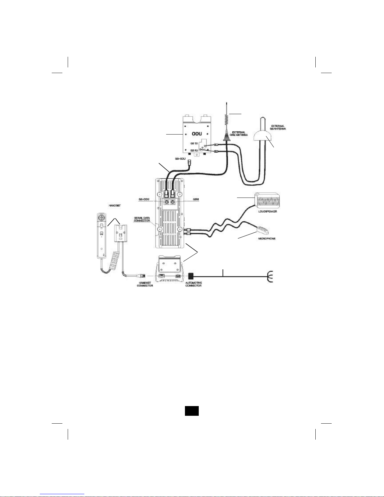
Installation Example
The installation of the car kit varies depending on the model of the vehicle.
The diagram below shows a possible installation of the various
components in the car kit.
ODU
GSM External
Antenna
(not supplied)
Globalstar
Antenna
Globalstar
wire
Microphone
Loudspeaker
Cradle
Manuale_551_Inglese_New
pagina 15
Martedì 29 Agosto 2000 10.56
Page 16

16
Installing the car kit
Installing the amplifier (ODU)
t Install the metal bracket for the amplifier and the four spacers
(provided in the pack), by fixing it to a metal panel using 4 screws
(not supplied).
Note: Before beginning to install the amplifier (for example in the
boot), check that it will be possible to connect it to the cradle using
the 5 m long Globalstar wire (provided in the pack) and the magnetic
external antenna (using the 2 m long antenna wire).
Manuale_551_Inglese_New
pagina 16
Martedì 29 Agosto 2000 10.56
Page 17

17
t Connect the coaxial wire for the Globalstar magnetic external antenna
to the red and black connectors on the amplifier.
t Insert the two metal lugs on the amplifier into the spaces provided on
the bracket, then fix in place using the screw provided in the pack.
t Fix the Globalstar wire to connect the amplifier to the cradle, using the
connector provided on the amplifier.
t Fix the front plastic casing to the amplifier using the central screw
(provided in the pack).
t Clip the plastic frame for the amplifier’s front casing in place by
pressing gently.
Metal lugs
Screw fixing to the
bracket
Globalstar external
antenna connectors
Globalstar wire
connector
Black
Red
Manuale_551_Inglese_New
pagina 17
Martedì 29 Agosto 2000 10.56
Page 18

18
Installing the cradle
Note: Position the cradle inside the vehicle so that it does not
interfere with normal driving operations, is not exposed to streams of
hot air coming from the vehicle’s heating system, and away from the
airbag.
Before installing the cradle bracket, check that it can be connected to
the amplifier (using the 5 m long Globalstar wire), the microphone
(using the 2.8 m long wire), the loudspeaker (using the 3 m wire),
the micro telephone and the vehicle’s IO devices.
t Fit the cradle bracket (the screws are not provided in the pack) to the
vehicle, choosing a position carefully that will allow easy, convenient use.
Manuale_551_Inglese_New
pagina 18
Martedì 29 Agosto 2000 10.56
Page 19

19
t Screw the vibration damping lugs (provided in the pack) onto the
cradle bracket.
Manuale_551_Inglese_New
pagina 19
Martedì 29 Agosto 2000 10.56
Page 20

20
t Connect the Globalstar cable to the TNC connector on the back of the
cradle, marked by the round red label.
t Connect the GSM 900MHz external antenna (not provided in the pack)
to the TNC connector on the back of the cradle, marked by a square
black label.
Globalstar wire
connector
GSM 900 MHz
antenna
connector
Manuale_551_Inglese_New
pagina 20
Martedì 29 Agosto 2000 10.56
Page 21

21
t Fix the cradle to the bracket using the washers and locknuts provided
in the pack.
Manuale_551_Inglese_New
pagina 21
Martedì 29 Agosto 2000 10.56
Page 22

22
Connectors and keys on the cradle
1. Cradle connector – Sat 550.
2. Connector Sat 550 – cradle.
3. Cradle antenna connectors – Sat 550.
4. Connector for external GSM 900 MHz antenna (optional).
5. Globalstar wire for connecting the cradle to the amplifier.
6. RS232, 9-pin data connector.
7. 2.5 mm mono audio connector for the microphone.
8. 3.5 mm stereo audio connector for the external speaker.
9. RJ45 type connector for the micro telephone.
10. Connector for vehicle IO devices.
11. Heat dissipator.
12. Key to release the Sat 550.
13. Key for adjusting hands-free and ring volume.
5 4 11
13 12
8
3
6
2
1 7
10 9
Manuale_551_Inglese_New
pagina 22
Martedì 29 Agosto 2000 10.56
Page 23

23
Installing the micro telephone
Note: Install the micro telephone inside the vehicle near the cradle,
being careful not to hamper normal driving operations and staying
clear of airbag openings.
t Secure the micro telephone bracket on a flat surface inside the vehicle
using two screws (not provided in the pack).
t Connect the micro telephone to the cradle using the (1.45 m wire) with
the RJ45 connector.
To the cradle
Micro telephone
bracket
Manuale_551_Inglese_New
pagina 23
Martedì 29 Agosto 2000 10.56
Page 24

24
Installing the microphone
Install the microphone in the upper portion of the vehicle body using the
relevant plastic bracket and two screws (provided in the pack), or on the
sun visor using the double-sided adhesive tape.
The microphone must face the driver’s mouth and not further than 40 cm
from his mouth.
Note: It is inadvisable to direct the stream of air from the air
conditioner towards the microphone, or to pass the wire connecting
the microphone to the cradle through an air conditioning duct.
Fit the wire connecting the microphone to the cradle in such a way
that it does not interfere with normal driving operations.
Manuale_551_Inglese_New
pagina 24
Martedì 29 Agosto 2000 10.56
Page 25

25
Installing the speaker
For best results, the speaker should be installed at least one metre from
the microphone and not facing it.
Remove (if the speaker is to be fixed) the speaker bracket by exercising
gentle outward pressure on it.
Secure the bracket on a flat surface inside the vehicle using two screws
(not provided in the pack). The ideal position for the speaker is near the front
passenger seat. Ensure that it does not interfere with the airbag opening.
Fit the speaker to the bracket.
Manuale_551_Inglese_New
pagina 25
Martedì 29 Agosto 2000 10.56
Page 26

26
Connecting to vehicle IO devices
t Ensure that the vehicle is switched off and that the battery terminals
have been removed before connecting the wires.
t Connect the red and then the white wire only after all the other wires
have been connected.
t Ensure that the connections have been formed tightly.
t Ensure that the wires do not interfere with, and that they are not
damaged by the movement of the seats, the pedals, or the handbrake.
Connect the wires in the following order:
t Connect the black (earth) wire to an unpainted metal surface in the
vehicle.
t Connect the blue (stereo mute) wire to the car radio, where fitted.
t Connect the red (+12 V) wire to the vehicle battery’s positive terminal.
Insert a 4 A retarded fuse in series with the power supply, on the
battery side.
t Connect the white (ignition) wire to the ignition indication if the ignition
key has an “ACC” position.
t Connect the microphone and speaker to the cradle.
t Connect the micro telephone to the cradle.
t Connect the cradle to the wires connecting it to the vehicle’s IO devices.
Manuale_551_Inglese_New
pagina 26
Martedì 29 Agosto 2000 10.56
Page 27

27
Advice for wire routing
t Where possible use existing ducts.
t When choosing a route for wires, ensure that they do not hamper the
movement of pedals, seats or the handbrake.
t Position the wires so that they do not interfere with other electronic
devices.
t Be sure to cut the connecting wires for the vehicle’s IO devices to the
required length.
t Ensure that the connection between the amplifier and the cradle is
inside the vehicle.
Manuale_551_Inglese_New
pagina 27
Martedì 29 Agosto 2000 10.56
Page 28

28
Using the car kit
Placing the Sat 550 in the cradle and removing it
To avoid damaging the Sat 550 telephone, before placing it in the cradle
check that the yellow key at the top of the cradle is pressed and the Sat
550 is switched off.
Insert the Sat 550 into the cradle from the top. Having pushed it down,
push it inwards until a click is heard which means that it has been secured.
The stop on the cradle will hook the base of the Sat 550 to prevent it
coming loose accidentally.
To remove the Sat 550 press the yellow key again and remove the
telephone carefully.
Note: Once the Sat 550 has been placed in the car kit, the indication
of an incoming call will be emitted via the speaker and not the
telephone.
Only remove the telephone after switching it off, and after pressing
the yellow button on the cradle to avoid damaging the telephone and
the cradle.
Manuale_551_Inglese_New
pagina 28
Martedì 29 Agosto 2000 10.56
Page 29

29
Switching on the telephone and the car kit
The telephone and the car kit switch on automatically when the vehicle‘s
ignition is switched on (if the white wire has been connected). For information
on operating the Sat 550, consult its instruction manual.
If the Sat 550 is correctly placed in the cradle, the display will show the
symbol H.
Note: Do not switch the telephone on when its use is forbidden or
when the unit could cause interference on dangerous situations.
Hands-free mode
Once the Sat 550 has been placed in the cradle and switched on, calls can
be made and received in hands-free mode immediately.
For best results in communication, we suggest you speak towards the
microphone. The caller’s voice will be heard over the external speaker.
Note: Always pay maximum attention to driving while having a
conversation.
Before making a call the vehicle must be stopped in a stopping zone.
Manuale_551_Inglese_New
pagina 29
Martedì 29 Agosto 2000 10.56
Page 30

30
Adjusting the volume in hands-free mode
To adjust the conversation volume when in hands-free mode, merely press
the keys on the side of the cradle. The upper key increases the volume,
the lower decreases volume.
The volume of the ring can be set using the same keys while the telephone
is in stand-by mode.
Note: The Sat 550 menu may also be used to adjust communication and
ring volumes, or the ## ** keys may be used. Consult the Sat 550
instruction manual.
Using the micro telephone
The micro telephone (included in the pack) may be used for a private
conversation. The hands-free mode is automatically disabled when the
micro telephone is removed, and can be reactivated by replacing the micro
telephone.
Note: The micro telephone is not to be used while driving. It must
only be used when the vehicle is stopped in a stopping zone.
A call can also be made in private mode:
t Remove the micro telephone from its support.
t Key in the telephone number on the Sat 550 keyboard.
t Press the s key.
To end the call simply press the e key.
Note: A call that started while the ignition was switched on will
continue until ended even when the vehicle‘s ignition is switched off
during the call.
Manuale_551_Inglese_New
pagina 30
Martedì 29 Agosto 2000 10.56
Page 31

31
Adjusting the volume on the micro telephone
The volume of a conversation in private mode can be adjusted by using
the volume adjuster on the side of the micro telephone.
Connecting to a Personal Computer
A laptop PC can be connected to the car kit, using the RS232, 9-pin
connector, to transmit data and faxes.
Note: The telephone cannot be used while you are transmitting or
receiving data.
An analogue facsimile machine cannot be connected directly to the
car kit to receive faxes.
Data transmission is a network service. Consult your service
provider for information on how to access this service.
Manuale_551_Inglese_New
pagina 31
Martedì 29 Agosto 2000 10.56
Page 32

32
Technical Information
Cradle Dimensions 220 x 90 x 40 mm
Cradle Weight 500 g
Cradle Operating Temperature 0 / +40° C
Cradle Storage Temperature -20° / +55° C
Globalstar Antenna Operating Temperature -10° / +50° C
Globalstar Antenna Storage Temperature -20° / +55° C
Car kit power supply
From the vehicle‘s battery:
ð Nominal Voltage: +12V;
ð Normal Voltage: +13.2V;
ð Minimum and maximum
Voltage: +10.8V / +15.6 V;
Microphone pre-amplifier
ð Maximum entry signal:
210 mV
rms
;
ð Maximum Distortion: 0.35%;
ð Maximum absorption: 10 mA
Speaker pre-amplifier
ð Maximum entry signal:
2.28 V
rms
;
ð Maximum output signal :
5.1V
rms
;
ð Maximum distortion: 5.77%;
ð Maximum absorption: 800 mA
Manuale_551_Inglese_New
pagina 32
Martedì 29 Agosto 2000 10.56
 Loading...