

Page 1

BlueMod+S42M
Hardware User Guide
1VV0301379 Rev. 4 – 2018-11-28
Page 2

BlueMod+S42M Hardware User Guide
1VV0301379 Rev. 4 Page 2 of 48 2018-11-28
SPECIFICATIONS ARE SUBJECT TO CHANGE WITHOUT NOTICE
NOTICE
While reasonable efforts have been made to assure the accuracy of this document, Telit
assumes no liability resulting from any inaccuracies or omissions in this document, or from
use of the information obtained herein. The information in this document has been carefully
checked and is believed to be reliable. However, no responsibility is assumed for
inaccuracies or omissions. Telit reserves the right to make changes to any products
described herein and reserves the right to revise this document and to make changes from
time to time in content hereof with no obligation to notify any person of revisions or changes.
Telit does not assume any liability arising out of the application or use of any product,
software, or circuit described herein; neither does it convey license under its patent rights
or the rights of others.
It is possible that this publication may contain references to, or information about Telit
products (machines and programs), programming, or services that are not announced in
your country. Such references or information must not be construed to mean that Telit
intends to announce such Telit products, programming, or services in your country.
COPYRIGHTS
This instruction manual and the Telit products described in this instruction manual may be,
include or describe copyrighted Telit material, such as computer programs stored in
semiconductor memories or other media. Laws in the Italy and other countries preserve for
Telit and its licensors certain exclusive rights for copyrighted material, including the
exclusive right to copy, reproduce in any form, distribute and make derivative works of the
copyrighted material. Accordingly, any copyrighted material of Telit and its licensors
contained herein or in the Telit products described in this instruction manual may not be
copied, reproduced, distributed, merged or modified in any manner without the express
written permission of Telit. Furthermore, the purchase of Telit products shall not be deemed
to grant either directly or by implication, estoppel, or otherwise, any license under the
copyrights, patents or patent applications of Telit, as arises by operation of law in the sale
of a product.
COMPUTER SOFTWARE COPYRIGHTS
The Telit and 3rd Party supplied Software (SW) products described in this instruction
manual may include copyrighted Telit and other 3rd Party supplied computer programs
stored in semiconductor memories or other media. Laws in the Italy and other countries
preserve for Telit and other 3rd Party supplied SW certain exclusive rights for copyrighted
computer programs, including the exclusive right to copy or reproduce in any form the
copyrighted computer program. Accordingly, any copyrighted Telit or other 3rd Party
supplied SW computer programs contained in the Telit products described in this instruction
manual may not be copied (reverse engineered) or reproduced in any manner without the
express written permission of Telit or the 3rd Party SW supplier. Furthermore, the purchase
of Telit products shall not be deemed to grant either directly or by implication, estoppel, or
otherwise, any license under the copyrights, patents or patent applications of Telit or other
3rd Party supplied SW, except for the normal non-exclusive, royalty free license to use that
arises by operation of law in the sale of a product.
Page 3

BlueMod+S42M Hardware User Guide
1VV0301379 Rev. 4 Page 3 of 48 2018-11-28
USAGE AND DISCLOSURE RESTRICTIONS
I. License Agreements
The software described in this document is the property of Telit and its licensors. It is
furnished by express license agreement only and may be used only in accordance with the
terms of such an agreement.
II. Copyrighted Materials
Software and documentation are copyrighted materials. Making unauthorized copies is
prohibited by law. No part of the software or documentation may be reproduced,
transmitted, transcribed, stored in a retrieval system, or translated into any language or
computer language, in any form or by any means, without prior written permission of Telit.
III. High Risk Materials
Components, units, or third-party products used in the product described herein are NOT
fault-tolerant and are NOT designed, manufactured, or intended for use as on-line control
equipment in the following hazardous environments requiring fail-safe controls: the
operation of Nuclear Facilities, Aircraft Navigation or Aircraft Communication Systems, Air
Traffic Control, Life Support, or Weapons Systems (High Risk Activities"). Telit and its
supplier(s) specifically disclaim any expressed or implied warranty of fitness for such High
Risk Activities.
IV. Trademarks
TELIT and the Stylized T Logo are registered in Trademark Office. All other product or
service names are the property of their respective owners.
V. Third Party Rights
The software may include Third Party Right software. In this case you agree to comply with
all terms and conditions imposed on you in respect of such separate software. In addition
to Third Party Terms, the disclaimer of warranty and limitation of liability provisions in this
License shall apply to the Third Party Right software.
TELIT HEREBY DISCLAIMS ANY AND ALL WARRANTIES EXPRESS OR IMPLIED
FROM ANY THIRD PARTIES REGARDING ANY SEPARATE FILES, ANY THIRD PARTY
MATERIALS INCLUDED IN THE SOFTWARE, ANY THIRD PARTY MATERIALS FROM
WHICH THE SOFTWARE IS DERIVED (COLLECTIVELY “OTHER CODE”), AND THE
USE OF ANY OR ALL THE OTHER CODE IN CONNECTION WITH THE SOFTWARE,
INCLUDING (WITHOUT LIMITATION) ANY WARRANTIES OF SATISFACTORY
QUALITY OR FITNESS FOR A PARTICULAR PURPOSE.
NO THIRD PARTY LICENSORS OF OTHER CODE SHALL HAVE ANY LIABILITY FOR
ANY DIRECT, INDIRECT, INCIDENTAL, SPECIAL, EXEMPLARY, OR CONSEQUENTIAL
DAMAGES (INCLUDING WITHOUT LIMITATION LOST PROFITS), HOWEVER CAUSED
AND WHETHER MADE UNDER CONTRACT, TORT OR OTHER LEGAL THEORY,
ARISING IN ANY WAY OUT OF THE USE OR DISTRIBUTION OF THE OTHER CODE
OR THE EXERCISE OF ANY RIGHTS GRANTED UNDER EITHER OR BOTH THIS
LICENSE AND THE LEGAL TERMS APPLICABLE TO ANY SEPARATE FILES, EVEN IF
ADVISED OF THE POSSIBILITY OF SUCH DAMAGES.
Page 4

BlueMod+S42M Hardware User Guide
1VV0301379 Rev. 4 Page 4 of 48 2018-11-28
APPLICABILITY TABLE
PRODUCTS
BLUEMOD+S42M/AI
BLUEMOD+S42M/AI3ATH
Page 5

BlueMod+S42M Hardware User Guide
1VV0301379 Rev. 4 Page 5 of 48 2018-11-28
CONTENTS
1. INTRODUCTION .......................................................................... 7
Scope ......................................................................................... 7
Audience .................................................................................... 7
Contact Information, Support ...................................................... 7
Text Conventions ....................................................................... 8
Related Documents .................................................................... 8
2. OVERVIEW .................................................................................. 9
3. GENERAL PRODUCT DESCRIPTION ...................................... 10
Feature Summary ..................................................................... 10
Applications .............................................................................. 11
Block Diagram .......................................................................... 12
4. APPLICATION INTERFACE ...................................................... 13
Power Supply ........................................................................... 13
Reset ........................................................................................ 14
Serial Interface ......................................................................... 15
I2C Interface ............................................................................. 17
General Purpose I/O (GPIO) .................................................... 17
Serial Wire Debug Interface ...................................................... 17
MEMS Sensors (Optional) ........................................................ 18
Test Mode ................................................................................ 19
Operating in a Power-Switched Environment............................ 19
5. MODULE PINS ........................................................................... 20
Pin Numbering .......................................................................... 20
Pin Allocation ............................................................................ 20
Pin Description ......................................................................... 21
Handling of Unused Signals ..................................................... 21
6. ELECTRICAL CHARACTERISTICS .......................................... 22
Absolute Maximum Ratings ...................................................... 22
Operating Conditions ................................................................ 22
Environmental Requirements ................................................... 22
DC Parameter .......................................................................... 23
Power Consumption and Power-Down Modes .......................... 24
RF Performance ....................................................................... 25
Antenna-Gain and Radiation Pattern ........................................ 26
Page 6

BlueMod+S42M Hardware User Guide
1VV0301379 Rev. 4 Page 6 of 48 2018-11-28
7. MECHANICAL CHARACTERISTICS ......................................... 28
Dimensions .............................................................................. 28
Recommended Land Pattern .................................................... 28
Re-flow Temperature-Time Profile ............................................ 29
Placement Recommendation .................................................... 30
Antenna Issues ......................................................................... 30
Housing Guidelines .................................................................. 30
Safety Guidelines ..................................................................... 30
Cleaning ................................................................................... 31
8. APPLICATION DIAGRAM.......................................................... 31
9. COMPLIANCES ......................................................................... 32
Declaration of Conformity CE ................................ ................... 32
SRRC Compliance ................................................................... 32
NCC Compliance ...................................................................... 32
Bluetooth Qualification .............................................................. 39
RoHS Declaration ..................................................................... 40
10. PACKING ................................................................................... 41
Tape&Reel Packing .................................................................. 41
Tray Packing ............................................................................ 43
Moisture Sensitivity Level ......................................................... 43
11. EVALUATION KIT ...................................................................... 44
12. SAFETY RECOMMENDATIONS................................................ 45
13. ACRONYMS ............................................................................... 46
14. DOCUMENT HISTORY .............................................................. 47
Page 7

BlueMod+S42M Hardware User Guide
1VV0301379 Rev. 4 Page 7 of 48 2018-11-28
1. INTRODUCTION
Scope
This document provides information how the BlueMod+S42M can be integrated into
customer systems. It addresses hardware specifications of the BlueMod+S42M and
requirements of the hardware environments for the BlueMod+S42M.
The description text “BlueMod+S42M” refers to all modules listed in the
Applicability Table.
Audience
This document is intended for Telit customers, especially system integrators, about to
implement Bluetooth modules in their application.
Contact Information, Support
For general contact, technical support services, technical questions and report
documentation errors contact Telit Technical Support at:
• TS-EMEA@telit.com
• TS-AMERICAS@telit.com
• TS-APAC@telit.com
• TS-SRD@telit.com
Alternatively, use:
https://www.telit.com/contact-us/
For detailed information about where you can buy the Telit modules or for recommendations
on accessories and components visit:
https://www.telit.com/
Our aim is to make this guide as helpful as possible. Keep us informed of your comments
and suggestions for improvements.
Telit appreciates feedback from the users of our information.
Page 8

BlueMod+S42M Hardware User Guide
1VV0301379 Rev. 4 Page 8 of 48 2018-11-28
Text Conventions
Danger – This information MUST be followed or catastrophic
equipment failure or bodily injury may occur.
Caution or Warning – Alerts the user to important points about
integrating the module, if these points are not followed, the module and
end user equipment may fail or malfunction.
Tip or Information – Provides advice and suggestions that may be
useful when integrating the module.
All dates are in ISO 8601 format, i.e. YYYY-MM-DD.
Related Documents
• [1] Bluetooth SIG Core SpecificationV4.2
• [2] UICP_UART_Interface_Control_Protocol, 30507ST10756A
• [3] BlueMod+S42M AT Command Reference, 80527ST10839A
• [4] BlueMod+S42M Software User Guide, 1VV0301391
• [5] BlueEva+S42M Evaluation Kit User Guide, 1VV0301390
Page 9

BlueMod+S42M Hardware User Guide
1VV0301379 Rev. 4 Page 9 of 48 2018-11-28
2. OVERVIEW
This document provides information how the BlueMod+S42M can be integrated into
customer systems. It addresses hardware specifications of the BlueMod+S42M and
requirements of the hardware environments for the BlueMod+S42M.
The term BlueMod+S42M is used as an abreviation and refers to
both, the BlueMod+S42M/AI and the BlueMod+S42M/AI3ATH.
If information is related to dedicated versions, the whole product
name is used.
The BlueMod+S42M is delivered in two different hardware versions:
• BlueMod+S42M/AI: with integrated bluetooth antenna and without additional
sensors
• BlueMod+S42M/AI3ATH: with integrated bluetooth antenna and with a 3 axis
acceleration sensor (3A) and a temperature and humidity sensor (TH)
The integration of the BlueMod+S42M bluetooth module within user
application shall be done according to the design rules described in
this manual.
The information presented in this document is believed to be accurate and reliable.
However, no responsibility is assumed by Telit Communications S.p.A. for its use, nor any
infringement of patents or other rights of third parties which may result from its use. No
license is granted by implication or otherwise under any patent rights of Telit
Communications S.p.A. other than for circuitry embodied in Telit products. This document
is subject to change without notice.
Page 10

BlueMod+S42M Hardware User Guide
1VV0301379 Rev. 4 Page 10 of 48 2018-11-28
3. GENERAL PRODUCT DESCRIPTION
Feature Summary
• Supports Bluetooth low energy
• Fully qualified Bluetooth V4.2 Single Mode LE
• CE certified
• SRRC and NCC certified
• Humidity sensor onboard (optional)
• 3 axis accelerometer onboard (optional)
• Fast connection setup
• RF output power typ 0dBm
• RF output power -40dBm in Whisper Mode
• High sensitivity design
• Supply voltage range 1,8V to 3,6V
• Internal crystal oscillator (40 MHz)
• LGA Surface Mount type. BlueMod+S42M: 17 x 10 x 2.6 mm3
• Pin compatible to Telit BlueMod+S, BlueMod+S42 and BlueMod+SR
• Shielded to be compliant to optional FCC full modular approval
• Flexible Power Management
• 128-bit AES encryption
• High-speed UART interface
• I2C Master
• Manufactured in conformance with RoHS2
• Weight: 0.65g
Page 11

BlueMod+S42M Hardware User Guide
1VV0301379 Rev. 4 Page 11 of 48 2018-11-28
Applications
The BlueMod+S42M is designed to be used in low power applications, like sensor devices.
Some typical applications are described in this chapter.
Supported profiles are:
• Terminal I/O
• GATT based LE-profiles
Support for any additional profile is possible on request.
3.2.1. General Cable Replacement
In case there is no standardized application specific profile available the BlueMod+S42M
offers Telit’s Terminal I/O profile, which allows transparent data transfer over UART and
supports Secure Simple Pairing, making the pairing process easy and the connection
secure. Terminal I/O is available for iOS and Android as well as implemented in Telit’s dual
mode module BlueMod+SR.
3.2.2. Industry
BlueMod+S42M can be used to monitor and control motors, actuators, values and entire
processes.
3.2.3. POS/Advertising
BlueMod+S42M supports iBeacon or similar applications.
3.2.4. Healthcare and Medical
Usage of Bluetooth is aimed mainly at devices that are used for monitoring vital data. Typical
devices are blood glucose meter, blood pressure cuffs and pulse ox meters. Bluetooth
BR/EDR and low energy were chosen by the Continua Health Alliance as transports for
interoperable end to end communication.
3.2.5. Sports and Fitness
In the sports and fitness segment the BlueMod+S42M is used in devices for positioning as
well as monitoring vital data. Typical devices in this market are heart rate monitors, body
temperature thermometers, pedometers, cadence meters, altimeter, positioning / GPS
tracking and watches displaying information from sensors.
3.2.6. Entertainment
Bluetooth technology is already used in a wide variety of devices in the entertainment
sector, namely set-top boxes / gaming consoles. BlueMod+S42M is especially suited for
use in remote controls, gaming controller and wireless mouse/keyboard applications.
Page 12
BlueMod+S42M Hardware User Guide
1VV0301379 Rev. 4 Page 12 of 48 2018-11-28
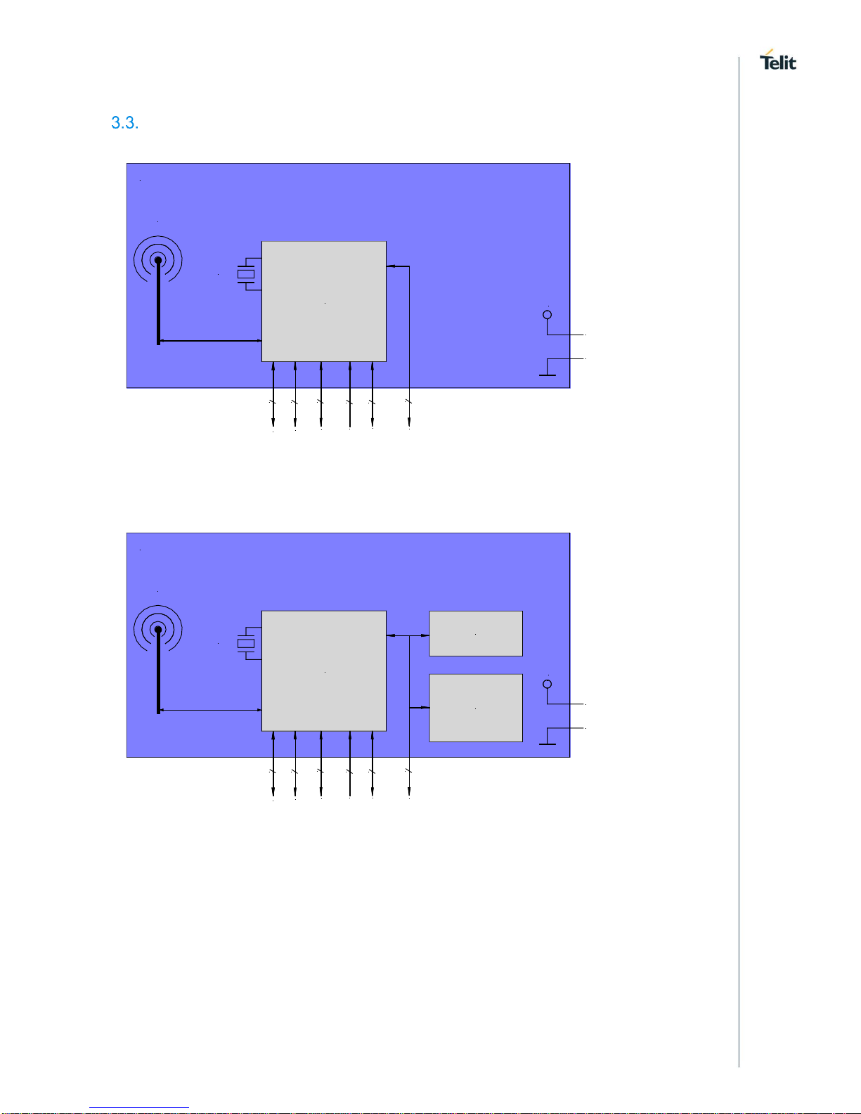
Block Diagram
BLE Single Chip
VSUP
BlueMod+S42M/AI
RESET
I2C
UART
SPI
1
2
up to 7
3
GND
3.0V
40MHz
SWD
onboard
antenna
GPIO
up to 2
2
Figure 1: BlueMod+S42M/AI Block Diagram
BLE Single Chip
VSUP
BlueMod+S42M/AI-3ATH
RESET
I2C
UART
SPI
1
2
up to 7
3
GND
3.0V
40MHz
SWD
onboard
antenna
GPIO
up to 2
2
Temp &
Humidity
Sensor (TH)
Motion
Sensor (3A)
Figure 2: BlueMod+S42M/AI3ATH Block Diagram
Page 13
BlueMod+S42M Hardware User Guide
1VV0301379 Rev. 4 Page 13 of 48 2018-11-28
4. APPLICATION INTERFACE
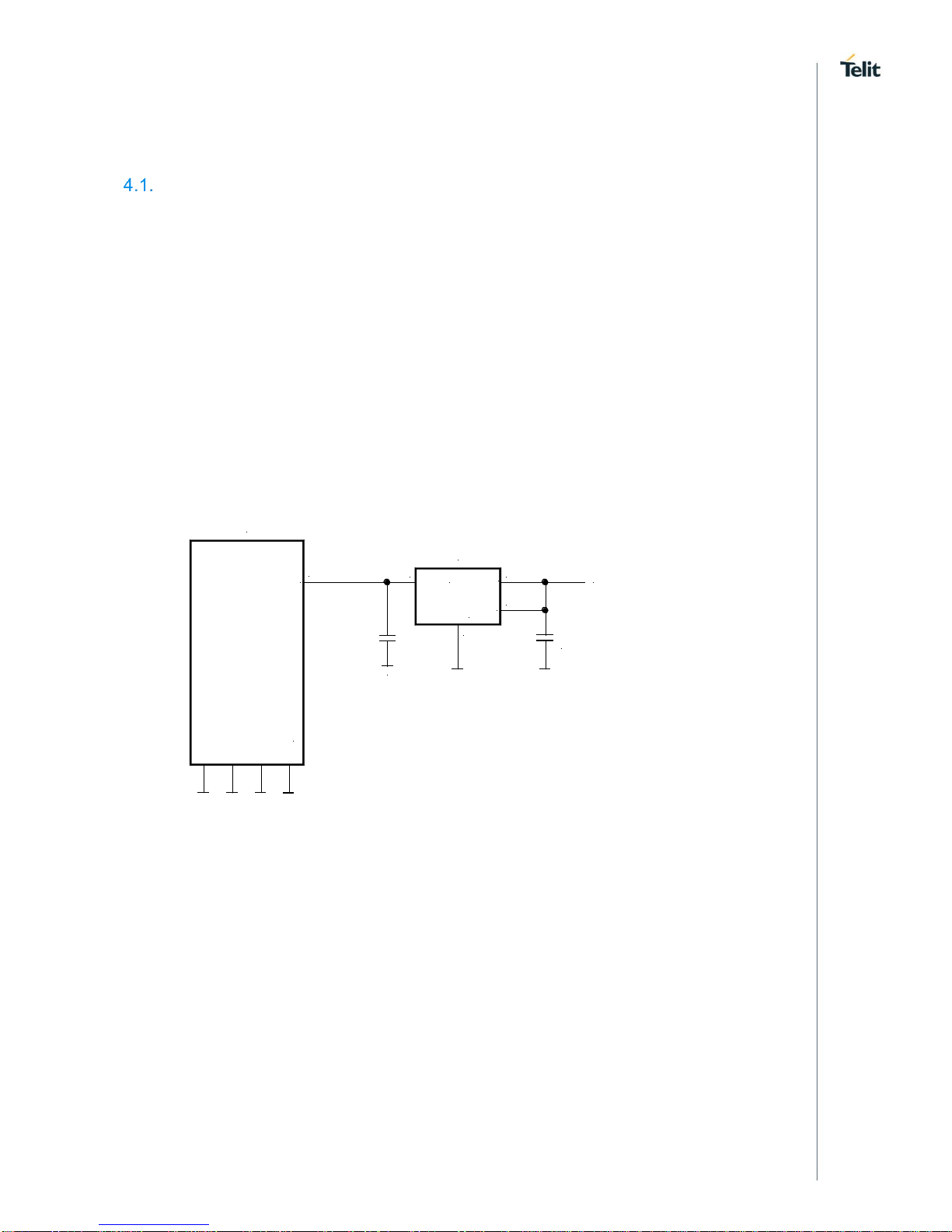
Power Supply
BlueMod+S42M require a power supply with the following characteristics:
Typical: 3,0VDC, min.: 1,8VDC, max.: 3,6VDC, thereby delivering > 25 mA peak
BlueMod+S42M is designed to be powered from 3V coin cell batteries e.g. CR2032 directly,
or any other power source complying with the given requirements. For optimal performance,
a stable supply is recommended. Furthermore, it is recommended to place a capacitor in
parallel to the CR2032 3V coin cell battery in order to prolong battery lifetime, by
compensating the effects of the rising source resistance of the battery to pulsed loads. Since
the isolation resistance of this capacitor will discharge the battery in a not insignificant scale,
the capacitor should be chosen under consideration of the following rules:
• capacitance as small as necessary
• nominal voltage as high as possible
• case size as large as possible
• use X7R instead of X5R
.
BlueMod+S42M
XC6209F-3.3
E-6,F-6
VSUP
GND:
A-7,E-7,F-7,B-[5:8],
C-[5:8],D-8,E-8,F-8
1µ + 100n
1µ
VOUT
VSS
VIN
CE
5 1
3
2
+5VDC
Figure 3: BlueMod+S42M Example Power Supply with LDO
Page 14

BlueMod+S42M Hardware User Guide
1VV0301379 Rev. 4 Page 14 of 48 2018-11-28
Reset
BlueMod+S42M are equipped with circuitry for generating reset from two sources:
• A reset is held active, when VSUP falls below the threshold of the Supply Voltage
Monitor (V
IT- =
1,67V), and is released when VSUP rises above V
IT-
+ V
HYST
.
• By holding pin B-1 (EXT-RES#) at ≤ VSUP*0,3V for t
HOLDRESETNORMAL
≥ 0,2µs, an
external reset (pin reset) is generated. This pin has a fixed internal pull-up resistor
(RPU = 10kΩ ... 30kΩ). EXT-RES# may be left open if not used.
BlueMod+S42M
E-6,F-6
VSUP
GND
+3V3
EXT-RES#
B-1
Reset-Switch is optional
Please Note: EXT-RES# of BlueMod+S42M has a 20k (range 10k to 30k) internal pullup.
Reset signal is optional
Host MCU
GPIO
VDD
Figure 4: BlueMod+S42M Example Reset
The following table shows the pin states of BlueMod+S42M during reset active.
Pin Name
State: BlueMod+S42M
EXT-RES#
Input with pull-up typ. 20kΩ
XL-IN
Input
XL-OUT
Output
SWDIO
Input with pull-up
(1)
SWCLK
Input with pull-up
(1)
all other port pins
Input with pull-down
(1)
(1)
pull-up, pull-down: R
PU, RPD
is typ. 10kΩ
Table 1: Pin States during Reset
If a logic signal driving EXT-RES# does not go fully to VSUP, some additional current is
drawn as a result of the internal pullup resistor on EXT-RES#. To minimize current draw,
an open drain driver or a logic-level FET as shown in Figure 5 can be used.
BlueMod+S42M
20k
EXT-RES#
VSUP
RES
EXT-RES
Figure 5: EXT-RES# with external FET
Page 15

BlueMod+S42M Hardware User Guide
1VV0301379 Rev. 4 Page 15 of 48 2018-11-28
Serial Interface
The serial interface of BlueMod+S42M is a high-speed UART interface supporting
RTS/CTS flow control and interface-up/down mechanism according to the UICP+ protocol
(refer to [2]).
Electrical interfacing is at CMOS levels (defined by VSUP; see chapter 6.4.1).
Transmission speeds are 9600 – 921600 bps and 1Mbps (asynchronous).
Character representation: 8 Bit, no parity, 1 stop bit (8N1).
Hardware flow-control with RTS and CTS (active low).
Transmission speed may be limited by firmware. See corresponding
AT command reference [3] for further information.
4.3.1. Basic Serial Interface
The basic serial interface (with RTS/CTS flow control) uses only four signal lines (UARTRXD, UART-TXD, UART-CTS#, UART-RTS#) and GND. IUR-IN#, IUR-OUT# and GPIO[4]
(see below) can be left unconnected.
BlueMod+S42M
Host
UART-RXD
UART-TXD
UART-CTS#
UART-RTS#
GND
Figure 6: Basic Serial Interface
If the host in question is sufficiently fast, a four-wire scheme may be successful. Connect
the serial lines UART-RXD, UART-TXD as well as UART-RTS# and GND; leave UARTCTS# open. The host is required to stop sending data within a short time after de-assertion
of UART-RTS# (there is room for up to 4 more characters at the time RTS# drops).
UICP has to be deactivated permanently in this configuration, because
signal UART-CTS# and IUR-IN# become inputs with no PU or PD if
UICP is active. This would cause floating CMOS inputs.
It is strongly recommended to use hardware flow control in both
directions. Not using flow control can cause a loss of data.
Page 16
BlueMod+S42M Hardware User Guide
1VV0301379 Rev. 4 Page 16 of 48 2018-11-28
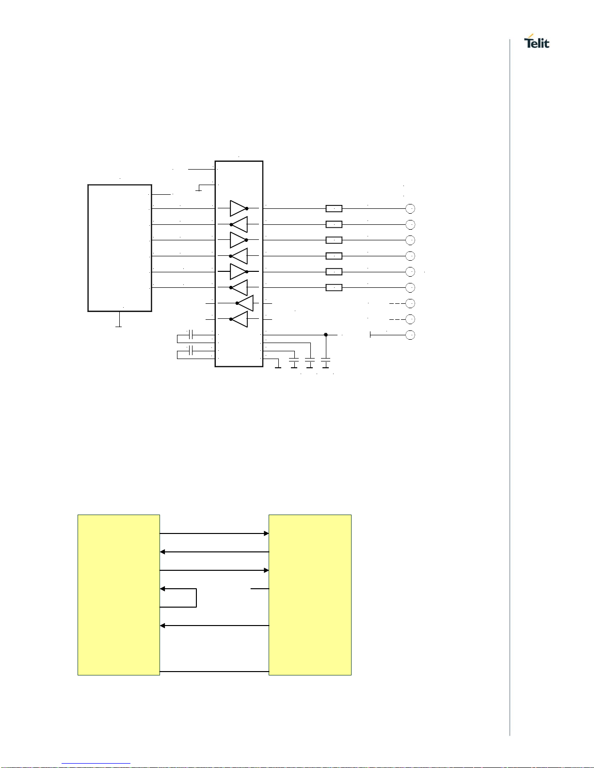
4.3.2. Serial Interface with UICP
A substantially saving of power during idle phases can be achieved (see 6.5.1) when the
UICP protocol is used (refer to [2]). This protocol should be implemented on the host side
as well. Signals IUR-IN# and IUR-OUT# should be connected to the host and may be
mapped to DSR and DTR, if an RS232-style (DTE-type) interface is used (see Figure 7).
2
BlueMod+S42M
GND
MAX3241
14
+3V3
22
23
2
3
7
8
4
6
1
9
TXD
RXD
RTS#
CTS#
IUR-OUT#
IUR-IN#
TXD
RXD
RTS
CTS
DTR
DSR
DCD
RI
RS232
DSUB9 (male)
9
4
10
5
11
6
7
8
19
13
18
12
17
16
15
F-4
D-2
D-7
F-3
B-4
D-5
UART_TXD
UART_RXD
UART_RTS#
UART_CTS#
IUR-OUT#
IUR-IN#
SHDN#
EN#
100n
100n
28
24
1
+3V3
100n
100n
100n
26
3
27
25
V+
VCC
V -
GND
C2+
C2-
C1+
C1-
220R
220R
220R
220R
220R
220R
5
SigGND
can be left open
VSUP
+3V3
DTE style connector pinout
Figure 7: BlueMod+S42M Example Serial Interface (RS-232) Supporting UICP
If I/O line availability at the host side is extremely tight, 2 I/O lines could be saved by using
the following scheme. This would come at the cost of
• The host is not allowed to enter sleep mode.
• The host must accept incoming data at all times and is not able to stop the
BlueMod+Sx sending data. This may be difficult to control for all scenarios and
adds the risk that data gets lost.
• The host doesn’t implement UICP, but wake-up BT via GPIO.
UART-TXD
GND
UART-RXD
IUC_IN# / CTS#
UART-RXD
UART-TXD
BlueMod
+Sx
Host
RTS#
CTS#
IUC_OUT# / RTS#
IUR_OUT#
IUR_IN# BM+Sx-WKUP
Figure 8: Five Wire Interface supporting UICP
Page 17

BlueMod+S42M Hardware User Guide
1VV0301379 Rev. 4 Page 17 of 48 2018-11-28
I2C Interface
The I2C bus interface serves as an interface between the internal microcontroller and the
serial I2C bus. BlueMod+S42M is the master and controls all I2C bus specific sequencing,
protocol and timing. It supports standard (100kHz) and fast (400kHz) speed modes. The
BlueMod+S42M as an I2C master must be the only master of the I2C bus (no multimaster
capability). Clock stretching is not supported.
SDA and SCL can be used to form an I2C interface. It is not required to connect pull-up
resistors on SCL and SDA when this interface is used.
SDA
SCL
SDA
SCL
BlueMod+S42M
VSUP
B-2
D-3
E-6,F-6
+3.0V
4k7
Figure 9: BlueMod+S42M I2C Interface
General Purpose I/O (GPIO)
Configuration and functionality of pins
• IOA
• IOB
• HANGUP
are described in [3]. Unused GPIO pins shall be left unconnected to stay compatible. There
may be functions assigned to some in future versions of the firmware.
Serial Wire Debug Interface
The Serial Wire Debug (SWD) interface (signals SWDIO, SWCLK) is normally not used in
a customer’s product. It is reserved for debugging purposes.
Leave SWDIO, SWCLK unconnected. Only if you intend to use them for debugging
purposes, make them available.
Page 18

BlueMod+S42M Hardware User Guide
1VV0301379 Rev. 4 Page 18 of 48 2018-11-28
MEMS Sensors (Optional)
The BlueMod+S42M includes optional an triaxial, low-g acceleration sensor, which
integrates a multitude of features that facilitate its use especially in the area of motion
detection applications, such as device orientation detection, navigation and spirit level
measurements. Featuring 14 bit digital resolution, the sensor allows very low-noise
measurement of accelerations in 3 perpendicular axes and thus senses tilt, motion, shock
and vibration.
Option: 3A
Furthermore the BlueMod+S42M includes optional an humidity and temperature sensor that
provides high accuracy measurements with very low power consumption.
The capacitive-based sensor provides high accuracy measurement capability for a wide
range of environmental monitoring applications and Internet of Things (IoT) such as smart
thermostats, smart home assistants and wearables. The sensor can also be used to provide
critical temperature and humidity data for cold chain transportation and storage of
perishable goods to help ensure products like food and pharma- ceuticals arrive fresh.
The sensor is factory-calibrated to 0.2°C temperature accuracy and 2% relative humidity
accuracy and includes a heating element to burn away condensation and moisture for
increased reliability.
Option: TH
The functionality of both sensors is highly Firmware dependent!
Please refer to [4] for further informations.
Page 19

BlueMod+S42M Hardware User Guide
1VV0301379 Rev. 4 Page 19 of 48 2018-11-28
Test Mode
For regulatory approval purposes, the ability of test mode operation like “Direct Test Mode”
(DTM) is mandatory. The Direct Test Mode (as defined by the Bluetooth SIG) is part of the
BlueMod+S42M.
For enabling the test mode the BlueMod+S42M provides the Testmode# IO pin. This pin is
low active, connect to GND to activate DTM.
To enter and use DTM, access to the following signals is required:
• TESTMODE#
• UART-RXD
• UART-TXD
• UART-RTS#
• UART-CTS#
• GND
These pins shall be routed to some test pads on an outer layer, but can be left open during
normal operation when not used.
Please note the UART is required for operation of DTM. For any
regulatory approval, UART-RXD, UART-TXD, UART-RTS# and
UART-CTS# must be freely accessible.
Operating in a Power-Switched Environment
A potential “back feeding” problem may arise, if the module is operated in an environment
where its power supply (VSUP) is switched off by the application. This might be done to
save some power in times Bluetooth is not needed.
As stated in Table 4, the voltage on any I/O pin must not exceed VSUP by more than 0,3V
at any time. Otherwise, some current I
INJ
flows through the internal protection diodes. This
may damage the module (please refer to chapter 6.1 for limits).
There is no problem if the application circuit design and programming can assure that all
signals directed towards BlueMod+S42M are set to low (U < 0,3V) before and while VSUP
is turned off. If this is not guaranteed, at least a series resistor (about 1k) must be inserted
into each signal path. This does protect the module but obviously cannot prevent from an
unwanted, additional current flow in case of such signal being at high-level. It may be
necessary to use driver chips in such applications, that gate off these signals while VSUP
is not present.
Page 20

BlueMod+S42M Hardware User Guide
1VV0301379 Rev. 4 Page 20 of 48 2018-11-28
5. MODULE PINS
Pin Numbering
F1
E1
D1
C1
B1
A1 A2 A3 A4 A5 A6 A7 A8
F2
E2
D2
C2
B2
F3
E3
D3
C3
B3
F4
E4
D4
C4
B4
F5
E5
D5
C5
B5
F6
E6
D6
C6
B6
F7
E7
D7
C7
B7
F8
E8
D8
C8
B8
Figure 10: BlueMod+S42M Pin Numbering (Top View)
Pin Allocation
1 2 3 4 5 6
7 8
A
DNU
DNU
DNU
DNU
DNU
DNU
GND
DNU
B
EXT-RES#
I2C-SDA
DNU
IUR-OUT#
GND
GND
GND
GND
C
DNU
DNU
DNU
DNU
GND
GND
GND
GND
D
DNU
UART-RXD
I2C-SCL
HANGUP
IUR-IN#
DNU
UART-RTS#
GND
E
DNU
IOA
DNU
IOB
DNU
VSUP
GND
GND
F
TESTMODE#
DNU
UART-CTS#
UART-TXD
DNU
VSUP
GND
GND
1 2 3 4 5 6
7 8
Table 2: BlueMod+S42M Pin Allocation (Top View)
Page 21
BlueMod+S42M Hardware User Guide
1VV0301379 Rev. 4 Page 21 of 48 2018-11-28
Pin Description
Pin Name
Signal
Function
Type
(1)
Act
Description
E-6
VSUP1
Power
PWR
+3,3V nom.
F-6
VSUP2
Power
PWR
+3,3V nom
A-7,E-7,F-7,
B-[5,6,7,8],
C-[5,6,7,8],
D-8,E-8,F-8
GND
GND
PWR
Ground
All GND pins must be connected
A-[1,2,3]
C-[1,2,3,4]
B-3 D-1 E-1
E-5 F-2 F-5
not connected
none
leave open
A-8
reserved
DNU
leave open
B-1
EXT-RES#
Reset
I-PU
L
User Reset
A-6
reserved
DNU
leave open
F-4
UART-TXD
TXD
O
Serial Data Transmit (OUT)
D-2
UART-RXD
RXD
I Serial Data Receive (IN)
D-7
UART-RTS#
/RTS
O
L
Flow Control Ready to Send
F-3
UART-CTS#
/CTS
I-PD
L
Flow Control Clear to Send
B-4
IUR-OUT#
/IUR-OUT
O
L
UICP Control
D-5
IUR-IN#
/IUR-IN
I L UICP Control
D-3
SCL
I2C-SCL
O
I2C-Clock Output
B-2
SDA
I2C-SDA
I/O-PU
I2C-Data In-/Output
E-4
IOB
GPIO
I/O
Firmware depent GPIO
D-4
HANGUP
Input
I-PD
Hangup Connection, FW depent
E-2
IOA
GPIO
I/O
Firmware depent GPIO
A-4
reserved
DNU
leave open, see warning below
F-1
TESTMODE#
Input
I-PU
L
Enable Direct Test Mode
E-3
SWDIO
DNU
Serial Wire Debug
D-6
SWCLK
DNU
Serial Wire Debug
A-5
reserved
DNU
leave open
(1)
PU: pull-up; PD: pull-down; PWR: Power; I: Input; O: Output; I/O: bidir; RF: RadioFreq; DNU: Do Not Use
Table 3: Pin Assignments
Handling of Unused Signals
Depending on the application, not all signals of BlueMod+S42M may be needed. The
following list gives some hints how to handle unused signals.
Signal
Handling
EXT-RES#
If no external Reset is needed: Leave open
UART-RXD
add a pullup (e.g.100kΩ) to VSUP
(1)
UART-TXD
leave UART-TXD open
(1)
UART-RTS#, UART-CTS#
If neither flow control nor UICP is used: Leave open
(1)(2)
IUR-OUT#, IUR-IN#
If UICP is not used: leave open
TESTMODE#
Leave open
(1)
unused GPIOs
Leave open
SWDIO, SWCLK
Leave open. Only needed for debug purposes
(1)
Signals must be accessible for regulatory approving
(2)
It is strongly recommended to use hardware flow control in both directions. Not using flow control can cause loss of data.
Table 4: Handling of Unused Signals
Page 22

BlueMod+S42M Hardware User Guide
1VV0301379 Rev. 4 Page 22 of 48 2018-11-28
6. ELECTRICAL CHARACTERISTICS
Absolute Maximum Ratings
Stresses beyond those listed under “Absolute Maximum Ratings” may cause permanent
damage to the device. These are stress ratings only and functional operation of the device
at these or any other conditions beyond those indicated under “Electrical Requirements” is
not implied. Exposure to absolute-maximum-rated conditions for extended periods may
affect device reliability.
Item
Symbol
Min
Max
Unit
Supply voltage
VSUP
-0,3
3,6 V Voltage on any pin
V
Pin
-0,3
VSUP+0,3 ≤ 3,6
V
Table 4: Absolute Maximum Ratings
Operating Conditions
T
amb
= 25°C
Item
Condition
Limit
Unit
Min
Typ
Max
Supply voltage VSUP
1,8
3,0
3,6
VDC
Table 5: DC Operating Conditions
Environmental Requirements
Item
Symbol
Absolute Maximum Ratings
Unit
Storage temperature range
T
stg
-40 to +125
°C
Operating temperature range
Top
-20 to +70
°C
Table 6: Environmental Requirements
Page 23

BlueMod+S42M Hardware User Guide
1VV0301379 Rev. 4 Page 23 of 48 2018-11-28
DC Parameter
6.4.1. General Purpose I/O (GPIO)
T
amb
= 25°C
Symbol
Item
Condition
Limit
Unit
Min
Typ
Max
VIL
Input Low Voltage
VSUP = 3,3V
VSUP = 2,8V
-
0
0,9
0,8
V
VIH
Input High Voltage
VSUP = 3,3V
VSUP = 2,8V
2
1,8
3,3
2,8
3,6
3,1
V
VOL
Output Low Voltage
VSUP = 3,3V
VSUP = 2,8V
0
-
0,33
0,28
V
VOH
Output High Voltage
VSUP = 3,3V
VSUP = 2,8V
2,97
2,5
-
3,3
3,1
V
IOL/IOH
Low and High Level
Output Current
A4, F1
VSUP=3.3V
-
20 - mA
Other Pads
VSUP=3.3V
- 8 -
mA
RPU/RPD
pull-up/down resistor
- 10 - kΩ
Table 7: DC Characteristics, Digital IO
6.4.2. Reset
BlueMod+S42M contains a voltage supervisory circuit that monitors VSUP.
The reset device initiates an internal reset signal whenever:
• VSUP drops below V
IT-
or
• EXT-RES# is ≤V
ILMR
The reset remains active for 200 ms (typical) after:
• VSUP rises above V
IT-
+ V
hys
and
• EXT-RES# is ≥V
IHMR
T
amb
= 25°C
Symbol
Item
Limit
Unit
Min
Typ
Max
V
(POR)
VSUP for valid reset function
0,6 V V
IT-
Negative going Threshold
1,628
1,670
1,695
V
V
hys
Hysteresis
17 mV
V
ILMR
EXT-RES# low-level input voltage
0,3VSUP
V
V
IHMR
EXT-RES# high-level input voltage
0,7VSUP
RPU
pull-up resistor
10
20
30
kΩ
Table 8: Reset Characteristics
Page 24

BlueMod+S42M Hardware User Guide
1VV0301379 Rev. 4 Page 24 of 48 2018-11-28
Power Consumption and Power-Down Modes
6.5.1. Terminal I/O Configuration
The following values are typical power consumption values in different states of operation.
BlueMod+S42M configured as a peripheral device.
VSUP = 3,0V, T
amb
= 25°C, all GPIO lines left open
Mode
Condition
Note
Current
Consumption (I
Avg
)
Tx power: 0dBm (max)
Unit
AI
AI3ATH
System off
CPU off, Radio inactive, 32k clock off,
SRAM Retention off
1 1,9
µA
Reset
Device hold in Reset
1,1
1,6
mA
UICP active
and
serial interface
down
Standby, Advertising Off (Radio
inactive)
1,2
2,2
µA
Standby, Advertising, 3 channels
advertising interval: 1.28s
25
28
µA
Connected,
connection interval: 1.28s
(1)
34
39
µA
Connected,
connection interval: 40ms
(1,2)
560
620
µA
UICP not
active
or
serial interface
up
Idle, Advertising Off (Radio inactive)
3,5
3,9
mA
Advertising, 3 channels
advertising interval: 1.28s
3,5
3,9
mA
Connected,
connection interval: 1.28s
(1)
3,5
3,9
mA
Connected,
connection interval: 40ms
(1,2)
3,5
3,9
mA
Connected,
connection interval: 7,5ms
(1)
3,7
4,1
mA
(1)
connection parameters are setup by the central device when connection is established
(2)
these are a typical connection parameters used by an iPhone, iPad or iPad mini device in the central device role
Table 9: Supply Current BLE Terminal I/O Profile, Peripheral Device Role
Page 25

BlueMod+S42M Hardware User Guide
1VV0301379 Rev. 4 Page 25 of 48 2018-11-28
RF Performance
6.6.1. BLE Receiver
VSUP = 3,0V, T
amb
= +25°C
Receiver
Conditions
Min
Typ
Max
BT Spec
Unit
Sensitivity
PER ≤ 30,8%
-94,0
≤ -70
dBm
max received input level
PER ≤ 30,8%
-1 ≥ -10
dBm
max PER report integrity
Wanted signal level -30dBm
2,426 Ghz
50 50 < PER < 65,4
%
Blocker Power
Wanted signal level -67dBm
0,030 – 2,000
-30
-30
dBm
2,000 – 2,400
-35
-35
2,500 – 3,000
-35
-35
3,000 – 12,75
-30
-30
Adjacent channel
Selectivity C/I
co-channel
6
≤21
dB
F = F0 + 1 MHz
-9 ≤15
dB
F = F0 - 1 MHz
-8 ≤15
dB
F = F0 + 2 MHz
-38 ≤-17
dB
F = F0 - 2 MHz
-32 ≤-15
dB
F = F0 + 3 MHz
-41 ≤-27
dB
F = Fimage
-26 ≤-9
dB
max intermodulation level
-50
≥-50
dBm
Table 10: RF Performance BLE Receiver
6.6.2. BLE Transmitter
VSUP = 1,7V to 3,6V, T
amb
= +20°C
Transmitter
Conditions
Min
Typ
Max
BT Spec
Unit
RF Transmit Power
-
0
-20 to +10
dBm
RF Frequency Range
-
2402 2480 MHz
RF Transmit Power
“Whisper Mode”
-
-40 N/A
dBm
Adjacent Channel Power
ACP
F = F0 ± 2MHz
≤ -20
dBm
F = F0 ± 3MHz
≤ -30
F = F0 ± > 3MHz
≤ -30
Modulation Characteristics
∆f1avg
250 225 … 275
kHz
∆f2max Thrsh. 185kHz
100 ≥ 99,9
%
∆f2avg / ∆f1avg
0,9 ≥ 0,8
Carrier Frequency Offset
and drift
Avg Fn
± 20 ± 150
kHz
avg drift
8
≤ 50
kHz
max drift rate
7,5 ≤ 20
kHz/50µs
Table 11: RF Performance BLE Transmitter
Page 26

BlueMod+S42M Hardware User Guide
1VV0301379 Rev. 4 Page 26 of 48 2018-11-28
Antenna-Gain and Radiation Pattern
If BlueMod+S42M is integrated into an end product while the recommendations depicted in
chapter 7.4 are maintained, the following typical antenna radiation patterns can be
expected.
Radiation Pattern will depend on the end products PCB size, masses in the antenna
environment, housing material and geometrics.
Typical antenna gain is about +2dBi.
Figure 11: Typical Antenna Radiation Pattern at 2402MHz
Figure 12: Typical Antenna Radiation Pattern at 2440MHz
Z
Y
X
Z
Y
X
Page 27

BlueMod+S42M Hardware User Guide
1VV0301379 Rev. 4 Page 27 of 48 2018-11-28
Figure 13: Typical Antenna Radiation Pattern at 2480MHz
Z
Y
X
Page 28
BlueMod+S42M Hardware User Guide
1VV0301379 Rev. 4 Page 28 of 48 2018-11-28
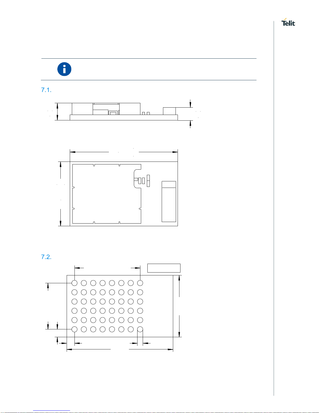
7. MECHANICAL CHARACTERISTICS
All dimensions are in millimeters.
Dimensions
17,0
+0,2
-0,0
10,0
+0,2
-0,0
2,0
+0,25
-0,25
2,6
+0,25
-0,25
Figure 14: BlueMod+S42M Dimensions
Recommended Land Pattern
F1
E1
D1
C1
B1
A1 A2 A3 A4 A5 A6 A7 A8
F2
E2
D2
C2
B2
F3
E3
D3
C3
B3
F4
E4
D4
C4
B4
F5
E5
D5
C5
B5
F6
E6
D6
C6
B6
F7
E7
D7
C7
B7
F8
E8
D8
C8
B8
1,25
1,25
7x1,5=10,5
5x1,5=7,5
0,9
17,0
10,0
Figure 15: BlueMod+S42M Land Pattern
TOP VIEW
Page 29

BlueMod+S42M Hardware User Guide
1VV0301379 Rev. 4 Page 29 of 48 2018-11-28
Re-flow Temperature-Time Profile
The data here is given only for guidance on solder and has to be adapted to your process
and other re-flow parameters for example the used solder paste. The paste manufacturer
provides a re-flow profile recommendation for his product.
Figure 16: Soldering Temperature-Time Profile (For Reflow Soldering)
Preheat
Main Heat
Peak
tsmax
tLmax
tpmax
Temperature
Time
Temperature
Time
Temperature
Time
[°C]
[sec]
[°C]
[sec]
[°C]
[sec]
150 100
217
90
260 10
230
50
Average ramp-up rate
[°C / sec]
3
Average ramp-down rate
[°C / sec]
6
Max. Time 25°C to Peak
Temperature
[min.]
8
Opposite side reflow is prohibited due to module weight.
Devices will withstand the specified profile and will withstand up to one re-flows to a
maximum temperature of 260°C. The reflow soldering profile may only be applied if the
BlueMod+S42M resides on the PCB side looking up. Heat above the solder eutectic point
while the BlueMod+S42M is mounted facing down may damage the module permanently.
Page 30

BlueMod+S42M Hardware User Guide
1VV0301379 Rev. 4 Page 30 of 48 2018-11-28
Placement Recommendation
To achieve best radio performance for BlueMod+S42M, it is recommended to use the
placement shown in Figure 17. This is a “corner placement” meaning the module is placed
such that the antenna comes close to the corner of the application PCB (red area). So, the
yellow area is outside the PCB and regards to the housing, too (refer to 7.6).
Please note that for best possible performance the antenna should be directed away from
the application PCB as shown in Figure 17.
max.0,5
4,5
10
10
max.0,5
10
15
no bare copper (exept solder pads for module)
no copper and components on any layer
no components on any layer
provide solid ground plane(s) as large as possible around
17
do not place any conductive parts in this area
20
20
40
area
Applic. PCB
Figure 17: BlueMod+S42M Placement Recommendation
Antenna Issues
BlueMod+S42M comprises a ceramic antenna, which as a component is soldered to the
circuit board. The performance of the antenna has to be checked within the final integration
environment. Adjacent PCBs, components, cables, housings etc. could otherwise influence
the radiation pattern or be influenced by the radio wave energy.
Housing Guidelines
The individual case must be checked to decide whether a specific housing is suitable for
the use of the internal antenna. A plastic housing must at least fulfill the following
requirements:
• Non-conductive material, non-RF-blocking plastics
• No metallic coating
• ABS is suggested
Safety Guidelines
According to SAR regulation EN 62479:2010 the BlueMod+S42M is not intended to be used
in close proximity to the human body. Please refer to above-mentioned regulation for more
specific information.
In respect to the safety regulation EN 62368-1:2014 + AC:2015 all conductive parts of the
BlueMod+S42M are to be classified as SELV circuitry. OEM’s implementing the
BlueMod+S42M in their products should follow the isolation rules given in regulation EN
62368-1:2014.
The PCB material of the BlueMod+S42M is classified UL-94V0.
Page 31

BlueMod+S42M Hardware User Guide
1VV0301379 Rev. 4 Page 31 of 48 2018-11-28
Cleaning
In general, cleaning the modules mounted on the host board is strongly discouraged.
Residues between module and host board cannot be easily removed with any cleaning
method.
• Cleaning with water or any organic solvent can lead to capillary effects where the
cleaning solvent is absorbed into the gap between the module and the host board.
The combination of soldering flux residues and encapsulated solvent could lead to
short circuits between conductive parts. The solvent could also damage any
labels.
• Ultrasonic cleaning could damage the module permanently. Especially for crystal
oscillators the risk of damaging is very high.
8. APPLICATION DIAGRAM
Figure 18 shows a typical application of BlueMod+S42M. The module is connected to some
MCU running the application layer. MCU and BlueMod+S42M use the same 3,3V power
supply. The serial interface has RTS/CTS flow control and UICP support in this example.
The optional hangup feature to close down the link is provided.
All other module pins may be left unconnected.
Host MCU
VDD
GND
+3V3
GPIO (o)
In this example BlueMod+S42M is connected to an MCU supporting UICP, RTS/CTS flow control and Hangup.
BlueMod+S42M/AI
E-6,F-6
VSUP
B-1
EXT-RES#
UART-RXD
UART-TXD
UART-CTS#
UART-RTS#
GPIO[4]/Hangup
TXD (o)
RXD (i)
RTS# (o)
CTS# (i)
GPIO (o)
B-4
D-4
all GND pads (14) must be connected.
Blocking capacitors not shown.
pushpull or OD
pushpull
D-2
F-4
F-3
D-7
IUR-IN#
D-5
IUR-OUT#
GPIO/DTR# (o)
GPIO/DSR# (i)
Figure 18: Typical Application Schematics
Page 32

BlueMod+S42M Hardware User Guide
1VV0301379 Rev. 4 Page 32 of 48 2018-11-28
9. COMPLIANCES
The BlueMod+S42M has been tested to comply with the appropriate EU, SRRC, NCC, FCC
and IC directives.
CE testing is intended for end products only. Therefore, CE testing is not mandatory for a
Bluetooth Module sold to OEM’s. However, Telit provides CE tested Modules for customers
in order to ease CE compliance assessment of end products and to minimize test effort.
Declaration of Conformity CE
The BlueMod+S42M fully complies with the essential requirements of the following EU
directives:
• RED 2014/53/EU
• RoHS 2011/65/EC (Assessment in progress)
The actual version of EU Declaration of Conformity (EU DoC) can be downloaded from
https://www.telit.com/RED/
SRRC Compliance
The BlueMod+S42M is certified in China according to the Radio regulations of the People’s
republic of China with the CMIIT ID: 2017DJ6332.
The actual version of the SRRC certificate can be downloaded from the Telit Download
Zone:
https://www.telit.com/support-training/download-zone/
Take note that you have to register to get access to the Download Zone.
NCC Compliance
9.3.1. NCC Warning Statement
• 經型式認證合格之低功率射頻電機,非經許可,公司、商號或使用者均不得擅自變更頻率
、加大功率或變更原設計之特性及功能。
• 低功率射頻電機之使用不得影響飛航安全及干擾合法通信;經發現有干擾現象時,應立即停
用,並改善至無干擾時方得繼續使用。前項合法通信,指依電信法規定作業之無線電通信。
低功率射頻電機須忍受合法通信或工業、科學及醫療用電波輻射性電機設備之干擾
Statement translation:
• Without permission granted by the NCC, any company, enterprise, or user is not allowed
to change frequency, enhance transmitting power or alter original characteristic as well as
performance to approved low power radio-frequency devices.
• The low power radio-frequency devices shall not influence aircraft security and interfere
legal communications; If found, the user shall cease operating immediately until no
interference is achieved. The said legal communications means radio communications is
operated in compliance with the Telecommunications Act. The low power radiofrequency devices must be susceptible with the interference from legal communications
or ISM radio wave radiated devices.
Page 33

BlueMod+S42M Hardware User Guide
1VV0301379 Rev. 4 Page 33 of 48 2018-11-28
9.3.2. NCC Label Requirements for End product
A product implementing the BlueMod+S42M and placed on the Taiwanese market has be
affixed with a label containing at least the following information.
CCAK17LP1710T3
9.3.3. Certificate
The actual version of the NCC certificate can be downloaded from the Telit Download Zone:
https://www.telit.com/support-training/download-zone/
Take note that you have to register to get access to the Download Zone.
FCC Compliance
The BlueMod+S42M has been tested to fulfill the FCC requirements. Test reports are
available on request.
9.4.1. FCC Grant
The actual version of the FCC Grant can be downloaded from the Telit Download Zone:
https://www.telit.com/support-training/download-zone/
Take note that you have to register to get access to the Download Zone.
9.4.2. FCC Statement
This device complies with 47 CFR Part 2 and Part 15 of the FCC Rules.
Operation is subject to the following two conditions:
(1) this device my not cause harmful interference, and
(2) this device must accept any interference received, including interference that may
cause undesired operation.
9.4.3. FCC Caution
WARNING:
Changes or modifications made to this equipment not expressly
approved by Telit may void the FCC authorization to operate this
equipment
Page 34

BlueMod+S42M Hardware User Guide
1VV0301379 Rev. 4 Page 34 of 48 2018-11-28
9.4.4. FCC Warning
This equipment has been tested and found to comply with the limits for a Class B digital
device, pursuant to Part 15 of the FCC Rules. These limits are designed to provide
reasonable protection against harmful interference in a residential installation. This
equipment generates, uses and can radiate radio frequency energy and, if not installed and
used in accordance with the instructions, may cause harmful interference to radio
communications. However, there is no guarantee that interference will not occur in a
particular installation. If this equipment does cause harmful interference to radio or
television reception, which can be determined by turning the equipment off and on, the user
is encouraged to try to correct the interference by one or more of the following measures:
• Reorient or relocate the receiving antenna.
• Increase the separation between the equipment and receiver.
• Connect the equipment into an outlet on a circuit different from that to which the
receiver is connected.
Consult the dealer or an experienced radio/TV technician for help.
9.4.5. FCC RF-exposure Statement
The BlueMod+S42M complies with the FCC/IC RF radiation exposure limits set forth for an
uncontrolled environment.
The output power is < 10mW EIRP and therefore according to “FCC OET KDB 447498 D01
General RF Exposure Guidance v05” Appendix A, table “SAR Exclusion Threshold”,
excluded from SAR testing for test separation distances ≥ 5mm and if it is not used in colocations with other antennas. If the product implementing the BlueMod+S42M has other
antennas in co-location or separation distances < 5mm, a MPE has to be re-evaluated.
9.4.6. FCC Labeling Requirements for the End Product
Any End Product integrating the BlueMod+S42M must be labeled with at least the following
information:
This device contains transmitter with
FCC ID: RI7-S42M
IC: 5131A-S42M
Page 35

BlueMod+S42M Hardware User Guide
1VV0301379 Rev. 4 Page 35 of 48 2018-11-28
IC Compliance
The BlueMod+S42M has been tested to fulfill the IC requirements. Test reports RSS-247 of
Industry Canada are available on request.
Le BlueMod + S42M a été testé pour répondre aux exigences de l’Indutrie du Canada.
Les rapports de test RSS-247 d'Industrie du Canada sont disponibles sur demande.
9.5.1. IC Grant
The actual version of the IC Grants can be downloaded from the Telit Download Zone:
https://www.telit.com/support-training/download-zone/
Take note that you have to register to get access to the Download Zone.
Le certificat fourni par L’Indutrie du Canada peut être téléchargé en ligne sur le site TELIT
suivant le lien ci-dessous :
https://www.telit.com/support-training/download-zone/
Prenez note que vous devez au prealable vous inscrire sur le site Telit pour accéder à la
zone de téléchargement.
9.5.2. IC Statement
(i) This device must be installed and operated in a fully enclosed enclosure to prevent RF
radiation that could otherwise interfere with aeronautical navigation. Installation must be
performed by qualified installers, in full compliance with the manufacturer's instructions.
(ii) This device can only be operated in a non-jamming and non-protection mode, i.e. the
user must accept that high power radars of the same frequency band can jam this device
or even damage it. On the other hand, level sensors that have been shown to interfere with
an operation authorized by a Master Operating License must be removed at the expense
of the user.
(i) Ce dispositif doit être installé et exploité dans une enceinte entièrement fermée afin de
prévenir les rayonnements RF qui pourraient autrement perturber la navigation
aéronautique. L’installation doit être effectuée par des installateurs qualifiés, en pleine
conformité avec les instructions du fabricant.
(ii) Ce dispositif ne peut être exploité qu’en régime de non-brouillage et de non-protection,
c’est-à-dire que l’utilisateur doit accepter que des radars de haute puissance de la même
bande de fréquences puissent brouiller ce dispositif ou même l’endommager. D’autre part,
les capteurs de niveau à propos desquels il est démontré qu’ils perturbent une exploitation
autorisée par licence de fonctionnement principal doivent être enlevés aux frais de leur
utilisateur.
This device complies with Industry Canada license-exempt RSS standard(s). Operation is
subject to the following two conditions:
(1) this device may not cause interference, and
(2) this device must accept any interference, including interference that may cause
undesired operation of the device.
Cet appareil est conforme aux normes RSS exemptes de licence de l’Industrie du Canada.
L'utilisation est soumise aux deux conditions suivantes:
(1) cet appareil ne doit pas causer d'interférences, et
Page 36

BlueMod+S42M Hardware User Guide
1VV0301379 Rev. 4 Page 36 of 48 2018-11-28
(2) cet appareil doit accepter toute interférence, y compris les interférences
susceptibles de provoquer un fonctionnement indésirable de l'appareil.
NOTICE:
This Class B digital apparatus complies with Canadian ICES-003.
Cet appareil numérique de la classe B est conforme à la norme NMB-003 en vigeur au
Canada.
Page 37

BlueMod+S42M Hardware User Guide
1VV0301379 Rev. 4 Page 37 of 48 2018-11-28
9.5.3. IC Caution
WARNING:
Telit has not approved any changes or modifications to this device by
the user. Any changes or modifications could void the user’s authority
to operate the equipment.
Telit n’approuve aucune modification apportée à l’appareil par
l’utilisateur, quelle qu’en soit la nature. Tout changement ou
modification peuvent annuler le droit d’utilisation de l’appareil par
l’utilisateur.
9.5.4. IC RF-exposure Statement
This equipment is portable device. According to RSS-102 Issue 5 §2.5.1 Exemption Limits
for Routine Evaluation – SAR Evaluation Table 1, the allowed distances to the human body
for products implementing the BlueMod+S42M can be calculated as follows. If the intended
use of the end product asks for smaller distances a new evaluation has to be repeated with
the end product.
• Max. RF output power is 0dBm
• Antenna peak Gain is +2dBi
• Resulting max. RF output power is +2dBm = 1.6mW < 4mW
• Table 1 of RSS-102 Issue 5 §2.5.1 shows that for 2450MHz the distance at 4mW
should be 5 mm
Cet équipement est un appareil portable. Selon le document RSS-102 Issue 5 §2.5.1
Exemption Limits for Routine Evaluation – SAR Evaluation Table 1, les distances
autorisées par rapport au corps humain pour les produits mettant en œuvre BlueMod +
S42M peuvent être calculées comme suit. Si l'utilisation prévue du produit final nécessite
de plus petites distances, une nouvelle évaluation doit être répétée avec le produit final.
• La puissance de sortie RF maximale est 0dBm
• Le gain l’antenne est +2dBi
• La puissance de sortie RF maximale résultante est +2dBm = 1.6mW < 4mW
• Le tableau 1 du document RSS-102, numéro 5, § 2.5.1 stipule que pour les
frequences de 2450 MHz, la distance à 4 mW doit être de 5 mm.
9.5.5. IC Labeling Requirements for the End Product
Any end product integrating the BlueMod+S42M must be labeled with at least the following
information:
This device contains transmitter with
Tout produit final intégrant le BlueMod + S42M doit porter au minimum les informations
suivantes:
Cet appareil contient un émetteur avec
FCC ID: RI7-S42M
IC: 5131A-S42
Page 38

BlueMod+S42M Hardware User Guide
1VV0301379 Rev. 4 Page 38 of 48 2018-11-28
9.5.6. IC Label Information BlueMod+S42M
The BlueMod+S42M shows the IC-ID on the product label.
Le BlueMod + S42M affiche l’IC-ID sur l’étiquette du produit.
Model: BlueMod+S42M
IC-ID: 5131A-S42M
Page 39

BlueMod+S42M Hardware User Guide
1VV0301379 Rev. 4 Page 39 of 48 2018-11-28
Bluetooth Qualification
The BlueMod+S42M is a qualified design according to the Bluetooth Qualification Program
Reference Document (PRD) V2.3.
The Declaration ID is:
D036716
The Qualified Design ID is:
99965
For further information about marking requirements of your product attention should be paid
the Bluetooth Brand Usage Guide at
https://www.bluetooth.org/en-us/bluetooth-brand/bluetooth-brand
According to the Bluetooth SIG rules (Bluetooth Declaration Process Document – DPD) you
must complete a Product Listing and Declaration of Compliance (DoC) referencing the
Qualified Design (QDID) for your product. For further information see www.Bluetooth.org or
contact Telit.
Page 40

BlueMod+S42M Hardware User Guide
1VV0301379 Rev. 4 Page 40 of 48 2018-11-28
RoHS Declaration
The BlueMod+S42M fully complies with the EU RoHS directive:
• RoHS 2011/65/EC
The actual version of RoHS Declaration of Conformity (EU DoC) can be downloaded from
the Telit Download Zone:
https://www.telit.com/support-training/download-zone
Take note that you have to register to get access to the Download Zone.
Page 41

BlueMod+S42M Hardware User Guide
1VV0301379 Rev. 4 Page 41 of 48 2018-11-28
10. PACKING
The BlueMod+S42M modules are packed either as Tape&Reel or as tray packing.
Tape&Reel Packing
The BlueMod+S42M modules are packed using carrier tape in this orientation.
pull off direction from reel
25 empty pockets as leader per packing unit
15 empty pockets as trailer per packing unit
module type + label as example only
ABC
ABC
ABC
ABC
Figure 19: Module Orientation in Carrier Tape
Page 42
BlueMod+S42M Hardware User Guide
1VV0301379 Rev. 4 Page 42 of 48 2018-11-28
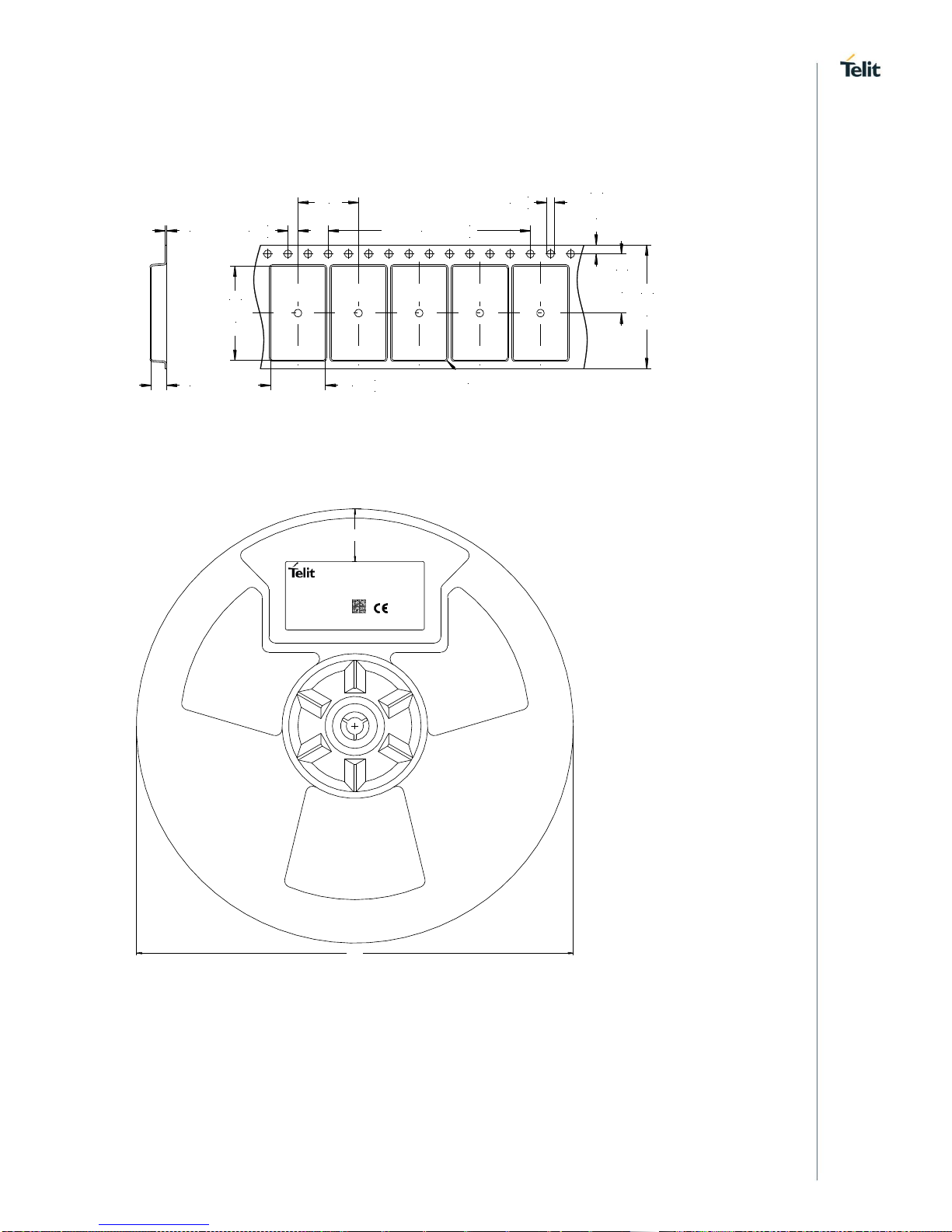
10.1.1. Tape
The dimensions of the tape are shown in Figure 20 (values in mm):
2,0
+0,1
-0,1
10,9
+0,1
-0,1
18,3
+0,1
-0,1
R 0,5
1,75
+0,10
-0,10
24,0
+0,3
-0,3
10x4,0=40,0
+0,2
-0,2
1,5
+0,1
-0,0
12,0
11,5
+0,1
-0,1
0,3
3,0
Figure 20: Carrier Tape Dimensions
10.1.2. Reel
name
p/n
firmware
fw p/n
trace
quantity
Designed in Germany, Made in China
XXXXXXXXXXXXXXXX
aaaaa-aa
b/c
ddddd-dd
mwwyy
q
FCC ID: RFRMS
IC: 4957A-MS
40
label content as example only
330
Figure 21: Reel Dimensions
Page 43

BlueMod+S42M Hardware User Guide
1VV0301379 Rev. 4 Page 43 of 48 2018-11-28
Tray Packing
10.2.1. Module Orientation
Figure 22: Module Orientation on Tray
10.2.2. Tray Dimensions
Figure 23: Tray Dimensions
Moisture Sensitivity Level
Moisture Sensitivity Level (MSL) for BlueMod+S42M is 3.
Page 44

BlueMod+S42M Hardware User Guide
1VV0301379 Rev. 4 Page 44 of 48 2018-11-28
11. EVALUATION KIT
Following evaluation kits are available:
• BLUEEVA+S42M/AI
• BLUEEVA+S42M/AI3ATH
Please refer to [5] for additional informations.
Page 45

BlueMod+S42M Hardware User Guide
1VV0301379 Rev. 4 Page 45 of 48 2018-11-28
12. SAFETY RECOMMENDATIONS
Read carefully
Be sure the use of this product is allowed in the country and in the environment required.
The use of this product may be dangerous and has to be avoided in the following areas:
• Where it can interfere with other electronic devices in environments such as
hospitals, airports, aircrafts, etc.
• Where there is risk of explosion such as gasoline stations, oil refineries, etc. It is the
responsibility of the user to enforce the country regulation and the specific
environment regulation.
Do not disassemble the product; any mark of tampering will compromise the warranty
validity. We recommend following the instructions of the hardware user guides for correct
wiring of the product. The product has to be supplied with a stabilized voltage source and
the wiring has to be conformed to the security and fire prevention regulations. The product
has to be handled with care, avoiding any contact with the pins because electrostatic
discharges may damage the product itself. Same cautions have to be taken for the SIM,
checking carefully the instruction for its use. Do not insert or remove the SIM when the
product is in power saving mode.
The system integrator is responsible for the functioning of the final product; therefore, care
has to be taken to the external components of the module, as well as any project or
installation issue, because the risk of disturbing the GSM network or external devices or
having impact on the security. Should there be any doubt, please refer to the technical
documentation and the regulations in force. Every module has to be equipped with a proper
antenna with specific characteristics. The antenna has to be installed with care in order to
avoid any interference with other electronic devices and has to guarantee a minimum
distance from the body (5 cm). In case this requirement cannot be satisfied, the system
integrator has to assess the final product against the SAR regulation.
The European Community provides some Directives for the electronic equipment
introduced on the market. All of the relevant information is available on the European
Community website:
http://ec.europa.eu/enterprise/sectors/rtte/documents/
The text of the Directive 99/05 regarding telecommunication equipment is available,
while the applicable Directives (Low Voltage and EMC) are available at:
http://ec.europa.eu/enterprise/sectors/electrical/
Page 46

BlueMod+S42M Hardware User Guide
1VV0301379 Rev. 4 Page 46 of 48 2018-11-28
13. ACRONYMS
TTSC Telit Technical Support Centre
USB Universal Serial Bus
DTE Data Terminal Equipment
UART Universal Asynchronous Receiver Transmitter
SPI Serial Peripheral Interface
I/O Input Output
GPIO General Purpose Input Output
CMOS Complementary Metal – Oxide Semiconductor
MOSI Master Output – Slave Input
MISO Master Input – Slave Output
CLK Clock
CS Chip Select
PCB Printed Circuit Board
ESR Equivalent Series Resistance
VSWR Voltage Standing Wave Radio
VNA Vector Network Analyzer
Page 47

BlueMod+S42M Hardware User Guide
1VV0301379 Rev. 4 Page 47 of 48 2018-11-28
14. DOCUMENT HISTORY
Revision
Date
Changes
0
2017-08-22
Initial release
1
2017-12-12
Chapter Compliances revised
Power consumption values added
2
2018-01-31
Operating temperature range extended to -20°C
Safety standard adapted to newer version
3
2018-10-19
Update power consumtion values of the AI3ATH variant
for UICP and systemoff
Added chapters FCC Compliance and IC Compliance
Updated Chapter 9.7
4
2018-11-28
Updated chapter IC Compliance with text in French
Page 48

 Loading...