

Page 1

BlueMod+S42/Central Software User Guide
1VV0301318 Rev. 3 – 2018-08-31
Reproduction forbidden without written authorization from Telit Communications S.p.A.- All Rights Reserved. Page 1 of 66
BlueMod+S42/Central
Software User Guide
1VV0301318 Rev. 3 – 2018-08-31
Page 2

BlueMod+S42/Central Software User Guide
1VV0301318 Rev. 3 – 2018-08-31
Reproduction forbidden without written authorization from Telit Communications S.p.A.- All Rights Reserved. Page 2 of 66
APPLICABILITY TABLE
PRODUCT
BlueMod+S42/Central
Page 3

BlueMod+S42/Central Software User Guide
1VV0301318 Rev. 3 – 2018-08-31
Reproduction forbidden without written authorization from Telit Communications S.p.A.- All Rights Reserved. Page 3 of 66
SPECIFICATIONS SUBJECT TO CHANGE WITHOUT NOTICE
Notice
While reasonable efforts have been made to assure the accuracy of this document, Telit assumes no
liability resulting from any inaccuracies or omissions in this document, or from use of the information
obtained herein. The information in this document has been carefully checked and is believed to be
entirely reliable. However, no responsibility is assumed for inaccuracies or omissions. Telit reserves the
right to make changes to any products described herein and reserves the right to revise this document and
to make changes from time to time in content hereof with no obligation to notify any person of revisions
or changes. Telit does not assume any liability arising out of the application or use of any product,
software, or circuit described herein; neither does it convey license under its patent rights or the rights of
others.
It is possible that this publication may contain references to, or information about Telit products
(machines and programs), programming, or services that are not announced in your country. Such
references or information must not be construed to mean that Telit intends to announce such Telit
products, programming, or services in your country.
Copyrights
This instruction manual and the Telit products described in this instruction manual may be, include or
describe copyrighted Telit material, such as computer programs stored in semiconductor memories or
other media. Laws in the Italy and other countries preserve for Telit and its licensors certain exclusive
rights for copyrighted material, including the exclusive right to copy, reproduce in any form, distribute
and make derivative works of the copyrighted material. Accordingly, any copyrighted material of Telit
and its licensors contained herein or in the Telit products described in this instruction manual may not
be copied, reproduced, distributed, merged or modified in any manner without the express written
permission of Telit. Furthermore, the purchase of Telit products shall not be deemed to grant either
directly or by implication, estoppel, or otherwise, any license under the copyrights, patents or patent
applications of Telit, as arises by operation of law in the sale of a product.
Computer Software Copyrights
The Telit and 3rd Party supplied Software (SW) products described in this instruction manual may
include copyrighted Telit and other 3rd Party supplied computer programs stored in semiconductor
memories or other media. Laws in the Italy and other countries preserve for Telit and other 3rd Party
supplied SW certain exclusive rights for copyrighted computer programs, including the exclusive right
to copy or reproduce in any form the copyrighted computer program. Accordingly, any copyrighted Telit
or other 3rd Party supplied SW computer programs contained in the Telit products described in this
instruction manual may not be copied (reverse engineered) or reproduced in any manner without the
express written permission of Telit or the 3rd Party SW supplier. Furthermore, the purchase of Telit
products shall not be deemed to grant either directly or by implication, estoppel, or otherwise, any license
under the copyrights, patents or patent applications of Telit or other 3rd Party supplied SW, except for
the normal non-exclusive, royalty free license to use that arises by operation of law in the sale of a
product.
Page 4

BlueMod+S42/Central Software User Guide
1VV0301318 Rev. 3 – 2018-08-31
Reproduction forbidden without written authorization from Telit Communications S.p.A.- All Rights Reserved. Page 4 of 66
Usage and Disclosure Restrictions
License Agreements
The software described in this document is the property of Telit and its licensors. It is furnished by
express license agreement only and may be used only in accordance with the terms of such an agreement.
Copyrighted Materials
Software and documentation are copyrighted materials. Making unauthorized copies is prohibited by
law. No part of the software or documentation may be reproduced, transmitted, transcribed, stored in a
retrieval system, or translated into any language or computer language, in any form or by any means,
without prior written permission of Telit.
High Risk Materials
Components, units, or third-party products used in the product described herein are NOT fault-tolerant
and are NOT designed, manufactured, or intended for use as on-line control equipment in the following
hazardous environments requiring fail-safe controls: the operation of Nuclear Facilities, Aircraft
Navigation or Aircraft Communication Systems, Air Traffic Control, Life Support, or Weapons Systems
(High Risk Activities"). Telit and its supplier(s) specifically disclaim any expressed or implied warranty
of fitness for such High Risk Activities.
Trademarks
TELIT and the Stylized T Logo are registered in Trademark Office. All other product or service names
are the property of their respective owners.
Third Party Rights
The software may include Third Party Right software. In this case you agree to comply with all terms
and conditions imposed on you in respect of such separate software. In addition to Third Party Terms,
the disclaimer of warranty and limitation of liability provisions in this License shall apply to the Third
Party Right software.
TELIT HEREBY DISCLAIMS ANY AND ALL WARRANTIES EXPRESS OR IMPLIED FROM
ANY THIRD PARTIES REGARDING ANY SEPARATE FILES, ANY THIRD PARTY MATERIALS
INCLUDED IN THE SOFTWARE, ANY THIRD PARTY MATERIALS FROM WHICH THE
SOFTWARE IS DERIVED (COLLECTIVELY “OTHER CODE”), AND THE USE OF ANY OR ALL
THE OTHER CODE IN CONNECTION WITH THE SOFTWARE, INCLUDING (WITHOUT
LIMITATION) ANY WARRANTIES OF SATISFACTORY QUALITY OR FITNESS FOR A
PARTICULAR PURPOSE.
NO THIRD PARTY LICENSORS OF OTHER CODE SHALL HAVE ANY LIABILITY FOR ANY
DIRECT, INDIRECT, INCIDENTAL, SPECIAL, EXEMPLARY, OR CONSEQUENTIAL
DAMAGES (INCLUDING WITHOUT LIMITATION LOST PROFITS), HOWEVER CAUSED AND
WHETHER MADE UNDER CONTRACT, TORT OR OTHER LEGAL THEORY, ARISING IN ANY
WAY OUT OF THE USE OR DISTRIBUTION OF THE OTHER CODE OR THE EXERCISE OF
ANY RIGHTS GRANTED UNDER EITHER OR BOTH THIS LICENSE AND THE LEGAL TERMS
APPLICABLE TO ANY SEPARATE FILES, EVEN IF ADVISED OF THE POSSIBILITY OF SUCH
DAMAGES.
Copyright © Telit Communications S.p.A. 2018.
Page 5

BlueMod+S42/Central Software User Guide
1VV0301318 Rev. 3 – 2018-08-31
Reproduction forbidden without written authorization from Telit Communications S.p.A.- All Rights Reserved. Page 5 of 66
Contents
1. Introduction ................................................................................................................... 7
1.1. Scope ....................................................................................................................... 7
1.2. Audience .................................................................................................................. 7
1.3. Contact Information, Support ................................................................................... 7
1.4. Text Conventions ..................................................................................................... 8
1.5. Related Documents .................................................................................................. 8
2. Introduction ................................................................................................................... 9
2.1. Overview .................................................................................................................. 9
2.2. Feature Set .............................................................................................................. 9
3. Modes and Connections ............................................................................................ 10
3.1. AT Command Mode ............................................................................................... 10
3.1.1. Central Role as GATT Client ...................................................................................... 10
3.1.2. Peripheral Role as Terminal I/O Server...................................................................... 18
3.1.3. Multiple GATT Connections ....................................................................................... 21
3.2. MUX Mode ............................................................................................................. 23
3.2.1. Central Role as GATT Client ...................................................................................... 23
4. Startup Timing ............................................................................................................ 32
4.1. Firmware Version 3.002 ......................................................................................... 32
5. Security ....................................................................................................................... 33
5.1. Pairable and Bondable Mode ................................................................................. 33
5.2. LE Secure Connections ......................................................................................... 33
5.3. Security Levels for Terminal I/O ............................................................................. 34
5.4. Connection Example Terminal I/O “Just Works” .................................................... 38
5.5. Connection Example Terminal I/O “Passkey Entry” ............................................... 39
6. UART Interface Control Protocol (UICP) ................................................................... 40
6.1. General Protocol Description ................................................................................. 40
6.2. Requirements of Using UICP on BlueMod+S42/Central ........................................ 40
6.3. Connection Example between BlueMod+S42/Central and Host Controller ............ 40
6.4. UICP Protocol States ............................................................................................. 41
6.4.1. Drive from "interface up" to "interface down" State ..................................................... 42
Page 6

BlueMod+S42/Central Software User Guide
1VV0301318 Rev. 3 – 2018-08-31
Reproduction forbidden without written authorization from Telit Communications S.p.A.- All Rights Reserved. Page 6 of 66
6.4.2. Drive from "interface down" to "interface up" State ..................................................... 43
6.5. Example of UICP Usage ........................................................................................ 44
6.5.1. State Change from "interface up" to "interface down" ................................................ 44
6.5.2. State Change from "interface down" to "interface up" ................................................ 45
7. NFC Handover ............................................................................................................. 46
7.1. NFC Mode .............................................................................................................. 46
7.2. NFC Handover Example ........................................................................................ 46
8. Firmware Upgrade ...................................................................................................... 48
8.1. Serial Firmware Upgrade ....................................................................................... 48
8.1.1. Prerequisites for Serial Firmware Upgrade ................................................................ 48
8.1.2. Telit IoT Updater ........................................................................................................ 48
8.1.3. Firmware Update Protocol on the Host System .......................................................... 50
8.2. Firmware Update over The Air (OTA) .................................................................... 53
8.2.1. Firmware Update Over The Air using Nordic nRF Toolbox on Android ...................... 54
9. System OFF Mode ...................................................................................................... 57
9.1. Using System OFF Mode for Terminal I/O ............................................................. 57
10. LE Connection Parameters ..................................................................................... 59
10.1. Create a Bluetooth Low Energy Connection ....................................................... 59
10.2. Optimize the Connection Interval from Slave by using the Slave Latency .......... 60
10.3. Identify the Required Connection Interval ........................................................... 61
10.4. Update the Connection Parameters .................................................................... 62
10.5. Connection Examples of Different Use Cases .................................................... 62
10.5.1. Central Side Initiates a GATT Connection .............................................................. 63
10.5.2. Central Side Changed Initial Connection Parameter ............................................... 64
10.5.3. Peripheral Side Create a Connection Parameter Update Request ......................... 65
11. Document History ................................................................................................... 66
Page 7

BlueMod+S42/Central Software User Guide
1VV0301318 Rev. 3 – 2018-08-31
Reproduction forbidden without written authorization from Telit Communications S.p.A.- All Rights Reserved. Page 7 of 66
1. Introduction
1.1. Scope
This document describes the usage of the BlueMod+S42/Central Bluetooth module.
1.2. Audience
This document is intended for Telit customers, especially system integrators, about to
implement Bluetooth modules in their application.
1.3. Contact Information, Support
For general contact, technical support, to report documentation errors and to order manuals,
contact Telit Technical Support Center (TTSC) at:
TS-SRD@telit.com
Alternatively, use:
https://www.telit.com/contact-us/
For detailed information about where you can buy the Telit modules or for recommendations
on accessories and components visit:
https://www.telit.com
To register for product news and announcements or for product questions contact Telit
Technical Support Center (TTSC).
Our aim is to make this guide as helpful as possible. Keep us informed of your comments and
suggestions for improvements.
Telit appreciates feedback from the users of our information.
Page 8
BlueMod+S42/Central Software User Guide
1VV0301318 Rev. 3 – 2018-08-31
Reproduction forbidden without written authorization from Telit Communications S.p.A.- All Rights Reserved. Page 8 of 66
1.4. Text Conventions
Danger – This information MUST be followed or catastrophic equipment failure or bodily
injury may occur.
Caution or Warning – Alerts the user to important points about integrating the module, if
these points are not followed, the module and end user equipment may fail or malfunction.
Tip or Information – Provides advice and suggestions that may be useful when integrating
the module.
All dates are in ISO 8601 format, i.e. YYYY-MM-DD.
1.5. Related Documents
[1] BlueMod+S42 Hardware User Guide, 1VV0301303
[2] BlueMod+S42/Central AT Command Reference, 80512ST10771A
[3] Bluetooth 4.0 Core Specification
[4] UICP+ UART Interface Control Protocol, 30507ST10756A
Page 9

BlueMod+S42/Central Software User Guide
1VV0301318 Rev. 3 – 2018-08-31
Reproduction forbidden without written authorization from Telit Communications S.p.A.- All Rights Reserved. Page 9 of 66
2. Introduction
2.1. Overview
This document describes the usage of the BlueMod+S42/Central Bluetooth module featuring
firmware version V3.001 or later.
For a detailed description of the commands refer to the BlueMod+S42/Central AT Command
Reference.
2.2. Feature Set
The combined central and peripheral BlueMod+S42/Central firmware includes the following
feature set:
• Handling for 4 parallel links (3 in central role and 1 in peripheral role)
• Generic GATT client support in central role
• Terminal I/O server role in peripheral role
• Up to 60 characteristics shared by all GATT clients
• 10 configurable 128 bit UUIDs
• Fix pin for easy security
• AT command mode and multiplexing mode
• Easy control over all connection parameters
• Advanced power saving features like UICP and SYSTEMOFF
• Firmware over the air update
This document shows the practical use of some commands listed in the AT command reference.
For command details it is referred to the BlueMod+S42/Central AT Command Reference.
Page 10

BlueMod+S42/Central Software User Guide
1VV0301318 Rev. 3 – 2018-08-31
Reproduction forbidden without written authorization from Telit Communications S.p.A.- All Rights Reserved. Page 10 of 66
3. Modes and Connections
In AT command mode the BlueMod+S42/Central supports 3 parallel central connections or one
peripheral Terminal I/O server connection. This means that the BlueMod+S42/Central stops
advertising (being connectable) as peripheral as soon a central connection is established.
When a peripheral Terminal I/O server connection is active, it is not possible to establish a
central connection to be used as GATT client.
The reason for this behavior is that a Terminal I/O connection in AT mode puts the serial
interface in data mode, where it is not possible to handle AT commands or events for an
additional central connection. Therefore it is not possible to use the ATD command for
connection establishment during a Terminal I/O connection.
To use peripheral and central connections in parallel the BlueMod+S42/Central supports the
multiplexing (MUX) mode. In this mode there is an always accessible AT command channel.
This makes it possible to handle all 4 links in parallel (3 central connections and one peripheral
Terminal I/O server connection). The host has to implement the simple to use multiplexing
protocol.
3.1. AT Command Mode
This chapter describes connection examples for different roles:
• Central role: GATT client connections to BLE peripheral devices in AT command mode
• Peripheral role as Terminal I/O server
3.1.1. Central Role as GATT Client
In central role the BlueMod+S42/Central supports the possibility to connect to any Bluetooth
low energy peripheral devices.
The following example lists the GATT connection in multiple steps include an explanation of
the different result messages.
Page 11

BlueMod+S42/Central Software User Guide
1VV0301318 Rev. 3 – 2018-08-31
Reproduction forbidden without written authorization from Telit Communications S.p.A.- All Rights Reserved. Page 11 of 66
3.1.1.1. Searching for Available Peripheral Devices
If the Bluetooth address of the peripheral device is unknown the BlueMod+S42/Central needs
to scan for available peripheral devices first.
AT+LESCAN=GATT
D0A4E9658F65,t3 RSSI:-60 TYPE:CONN
NAME:BM+S 8F65
MNF:8F0009B0011000
UUID:FEFB
DE338F0D1A22,t3 RSSI:-68 TYPE:CONN
NAME:BM+S 1A22
MNF:8F0009B0011000
UUID:FEFB
0080254978B3,t2 RSSI:-62 TYPE:CONN
NAME:BM+SR 7
MNF:8F0009B0011000
UUID:53544D544552494F5345525631303030
UUID:FEFB
F1B9EB41D81E,t3 RSSI:-57 TYPE:CONN
NAME:TESTDEVICE
UUID:FF00
008025001162,t2 RSSI:-68 TYPE:CONN
NAME:BM+SR 1
MNF:8F0009B0011000
UUID:53544D544552494F5345525631303030
UUID:FEFB
OK
This output lists 5 different peripheral devices with different services.
To list peripheral devices with a specific UUID it is possible to add this UUID value in the
AT+LESCAN command.
AT+LESCAN=uFF00
F1B9EB41D81E,t3 RSSI:-57 TYPE:CONN
NAME:TESTDEVICE
UUID:FF00
OK
The found peripheral device includes the following information:
Bluetooth address and type: F1B9EB41D81E,t3
Signal strength in dbm: RSSI:-57
Advertisement type: TYPE:CONN
Device name: NAME:TESTDEVICE
Service UUID: UUID:FF00
Page 12

BlueMod+S42/Central Software User Guide
1VV0301318 Rev. 3 – 2018-08-31
Reproduction forbidden without written authorization from Telit Communications S.p.A.- All Rights Reserved. Page 12 of 66
3.1.1.2. Create GATT Connection
To establish a GATT connection to a peripheral device it is required to initiate a call request to
the unique Bluetooth address.
ATDF1B9EB41D81E,t3,GATT
CONNECT GATT 0x10
The BlueMod+S42/Central reports the created GATT connection with the result message
„CONNECT“ include the connection type „GATT“ and a connection handle “0x10”.
This connection handle is not set to a fixed value and will be different for each connection.
The given connection handle is required for further activities onto this peripheral device.
3.1.1.3. Discovering Services and Characteristics
After the GATT connection was established the BlueMod+S42/Central should search for
available services and their characteristics using the AT+LESRVD command.
AT+LESRVD=0x10
UUID:1800
UUID:1801
UUID:180A
UUID:FF00
OK
The BlueMod+S42/Central reports a list of GATT services from the peripheral device.
This list of available services also includes the UUID: “FF00”. This UUID was listed during
the LESCAN result of this peripheral device as well. If the required service UUID is already
known, the service search function could be skipped.
In addition to the service UUID value it is required to get the characteristic values of the
required service UUID.
Page 13

BlueMod+S42/Central Software User Guide
1VV0301318 Rev. 3 – 2018-08-31
Reproduction forbidden without written authorization from Telit Communications S.p.A.- All Rights Reserved. Page 13 of 66
AT+LESRVD=0x10,uFF00
UUID:FF00
0x0011 PROP:0x3E UUID:FF01
0x0014 PROP:0x3E UUID:FF02
0x0017 PROP:0x3E UUID:FF03
0x001A PROP:0x08 UUID:FF04
0x001C PROP:0x04 UUID:FF05
0x001E PROP:0x02 UUID:FF06
0x0020 PROP:0x10 UUID:FF07
0x0023 PROP:0x20 UUID:FF08
0x0026 PROP:0x30 UUID:FF09
0x0029 PROP:0x3E UUID:FF0A
0x002C PROP:0x3E UUID:FF0B
0x002F PROP:0x3E UUID:FF0C
0x0032 PROP:0x3E UUID:FF0D
0x0035 PROP:0x3E UUID:0000FF0A000010008000008025000000
0x0038 PROP:0x3E UUID:0000FF0B000010008000008025000000
0x003B PROP:0x3E UUID:0000FF0C000010008000008025000000
0x003E PROP:0x3E UUID:0000FF0D000010008000008025000000
OK
The BlueMod+S42/Central reports a list of GATT characteristics of the requested GATT
service UUID: “FF00” from the peripheral device. This list of characteristics includes all
characteristic specific values like, characteristic handle, characteristic properties, characteristic
UUID.
The following example lists the information of the first characteristic in details:
characteristic handle: 0x0011
characteristic properties: PROP:0x3E
characteristic UUID: UUID:FF01
The characteristic handle is required for all access functions to use with this characteristic.
The characteristic properties inform about the possible access functions available on this
characteristic, like: read, write, write without response, notify, indicate. In this example the
properties PROP: 0x3E with the characteristic handle 0x0011 are set to all possible properties.
The characteristic UUID identifies the characteristic ID within this service.
Page 14

BlueMod+S42/Central Software User Guide
1VV0301318 Rev. 3 – 2018-08-31
Reproduction forbidden without written authorization from Telit Communications S.p.A.- All Rights Reserved. Page 14 of 66
3.1.1.4. Writing Data to a Characteristic
To write data to a characteristic it is required that the properties of this characteristic support
“write” or “write without response”.
There are two different options to write data to the characteristic:
• AT+LEWRITE: Initiate a write with response access
to the characteristic
• AT+LEWRITECMD: Initiate a write without response access
(write command) to the characteristic
In addition it is important to know the data size of the GATT characteristic.
This information is listed in the service specification of the addressed service.
In the example the data size is defined to two bytes.
To write two data bytes (0xaa and 0xbb) to the GATT server on the peripheral side the host
controller needs to use the connection handle and characteristic handle from the ATD and
AT+LESRVD commands. Additionally the data content has to be added to the command line.
AT+LEWRITE=0x10,0x0011,aabb
OK
The command “AT+LEWRITE” uses a “write request” command which is confirmed by the
peripheral side with a “write response” message.
The result “OK” means that the value was written to the peripherals GATT server successfully.
AT+LEWRITECMD=0x10,0x0011,aabb
OK
The command “AT+LEWRITECMD” uses a “write command” which is not confirmed by the
peripheral side. The result “OK” means that the data was sent over the air.
Page 15

BlueMod+S42/Central Software User Guide
1VV0301318 Rev. 3 – 2018-08-31
Reproduction forbidden without written authorization from Telit Communications S.p.A.- All Rights Reserved. Page 15 of 66
3.1.1.5. Reading Data from a Characteristic
To read data from a characteristic it is required that the properties of this characteristic supports
“read”, “notify” or “indicate”.
To read data bytes from a characteristic of the GATT server on the peripheral side the host
controller needs to use the connection handle and characteristic handle from the ATD and
AT+LESRVD commands.
AT+LEREAD=0x10,0x0011
LEREAD:0x10,0x0011,AABB
OK
The answer is separated into two parts:
The result message “OK” reports that reading to the required connection handle and
characteristic handle was successful.
The “LEREAD:0x10,0x0011,AABB” message reports the read data of the requested
connection handle “0x10” and characteristic handle “0x0011”.
The data is formatted as a hexadecimal stream “AABB” that includes two bytes 0xAA and
0xBB.
3.1.1.6. Reading Data with Indications or Notifications
Indications and notifications are messages that inform the GATT client when a characteristic
on the GATT server changes its value.
▪ INDICATIONS: The GATT client generated a response to the GATT server when
receiving data
• NOTIFICATIONS: The GATT client generated no response to the GATT server when
receiving data
This feature has to be enabled by the client for a specific characteristic.
It is not possible to enable indications and notifications at the same time.
To use this feature, it is required that the properties of the characteristic supports “notify” or
“indicate”. This information is given in the service discovery for the characteristic in the “PROP”
value.
Page 16

BlueMod+S42/Central Software User Guide
1VV0301318 Rev. 3 – 2018-08-31
Reproduction forbidden without written authorization from Telit Communications S.p.A.- All Rights Reserved. Page 16 of 66
3.1.1.6.1. Enable Notifications:
AT+LECCCD=0x10,0x0011,1
OK
The result message “OK” reports that activating notifications to the required connection handle
and characteristic handle was successful.
When the data of this characteristic on the GATT server changed to “0x36, 0x37” the
BlueMod+S42/Central generates an event (“LENOTI”) that reports these changes:
LENOTI:0x10,0x0011,3637
The reported “LENOTI” event of the BlueMod+S42/Central contains the new data of the
characteristic with handle “0x0011” and connection handle “0x10”.
The data is formatted as a hexadecimal stream “3637” that includes two bytes 0x36 and 0x37.
Every data change on the remote GATT server characteristic generates a new “LENOTI” event
until the notifications to this characteristic are switched off.
3.1.1.6.2. Disable Notifications:
AT+LECCCD=0x10,0x0011,0
OK
The result message “OK” reports that deactivating the notifications to the required connection
handle and characteristic handle was successful.
3.1.1.6.3. Enable Indications:
AT+LECCCD=0x10,0x0011,2
OK
The result message “OK” reports that activating indications to the required connection handle
and characteristic handle was successful.
When the data of this characteristic on the GATT server changed to “0x36, 0x38” the
BlueMod+S42/Central generates an event (“LEIND”) that reports these changes:
LEIND:0x10,0x0011,3638
The reported “LEIND” event of the BlueMod+S42/Central contains the new data of the
characteristic with handle “0x0011” and connection handle “0x10”.
The data is formatted as a hexadecimal stream “3638” that includes two bytes 0x36 and 0x38.
Every data change on the remote GATT server characteristic generates a new “LEIND” event
until the indications to this characteristic are switched off.
Page 17

BlueMod+S42/Central Software User Guide
1VV0301318 Rev. 3 – 2018-08-31
Reproduction forbidden without written authorization from Telit Communications S.p.A.- All Rights Reserved. Page 17 of 66
3.1.1.6.4. Disable Indications:
AT+LECCCD=0x10,0x0011,0
OK
The result message “OK” reports that deactivating the indications to the required connection
handle and characteristic handle was successful.
3.1.1.6.5. Close Connection:
When the connection is not needed anymore, it could be disconnected. To close a GATT
connection to a peripheral device the host controller needs to use the connection handle.
ATH=0x10
NO CARRIER 0x10
The response of the disconnect request “ATH” is the event “NO CARRIER” followed by
disconnected connection handle.
The same event is reported when the remote peripheral disconnects the connection.
It is also possible to disconnect all existing GATT connection to different peripheral devices
by using the GPIO “HANGUP”.
Page 18
BlueMod+S42/Central Software User Guide
1VV0301318 Rev. 3 – 2018-08-31
Reproduction forbidden without written authorization from Telit Communications S.p.A.- All Rights Reserved. Page 18 of 66
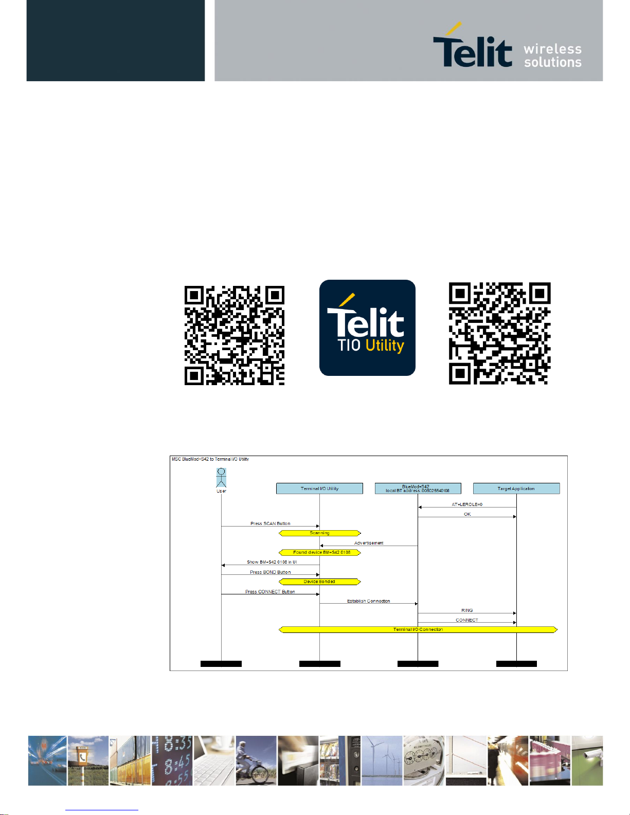
3.1.2. Peripheral Role as Terminal I/O Server
A Terminal I/O connection to the BlueMod+S42/Central can be created from each Bluetooth
Low Energy device that supports the Terminal I/O client role.
Telit provide the Terminal I/O client implementation for iOS and Android.
To establish a Bluetooth Low Energy connection from a smartphone to the
BlueMod+S42/Central the "Terminal IO Utility" app from Telit needs to be installed on the
smartphone.
The following QR-Codes provide the link to download the "Terminal IO Utility" app.
iOS
Logo
Android
The Terminal IO Utility app allows the user to connect to Terminal I/O peripheral devices
(BlueMod+S42/Central) and exchange data providing a simple terminal emulation.
As soon as the connection is established data can be sent from the smartphone to
BlueMod+S42/Central and vice versa.
Page 19

BlueMod+S42/Central Software User Guide
1VV0301318 Rev. 3 – 2018-08-31
Reproduction forbidden without written authorization from Telit Communications S.p.A.- All Rights Reserved. Page 19 of 66
3.1.2.1. Incoming Terminal I/O Connection
For a Terminal I/O connection it is necessary that the Terminal I/O service and the advertising
mode are enabled. This is the default behavior of the BlueMod+S42/Central.
The BlueMod+S42/Central signals an incoming Terminal I/O connection with the following
event:
RING
CONNECT TIO 0x01
The BlueMod+S42/Central report the incoming Terminal I/O connection with the result
message “RING”. The established Terminal I/O connection is reported with the message
„CONNECT“ including the connection type „TIO“ and a connection handle “0x01”.
The given connection handle is required for detailed activities onto this Terminal I/O
connection.
After reporting the “CONNECT” result message the BlueMod+S42/Central changed from the
AT based “command mode” to the “online data mode”.
3.1.2.2. Exchange Terminal I/O Data
All data send on the serial interface is transparently sent to the Terminal I/O client side.
All data send by the remote Terminal I/O client is binary output on the serial interface of the
BlueMod+S42/Central.
When a peripheral Terminal I/O server connection is active, it is not possible to create a GATT
connection to a peripheral device.
Page 20

BlueMod+S42/Central Software User Guide
1VV0301318 Rev. 3 – 2018-08-31
Reproduction forbidden without written authorization from Telit Communications S.p.A.- All Rights Reserved. Page 20 of 66
3.1.2.3. Close Terminal I/O Connection
The Terminal I/O connection can be closed in the following two different options:
• By using the GPIO “HANGUP”
(only available if this GPIO is controlled by the host controller)
• Send the “ATH” command.
Using the GPIO “HANGUP”
set GPIO “HANGUP” to high level
set GPIO “HANGUP” to low level
NO CARRIER 0x01
Using the “ATH” command
<wait 1 sec after data exchange>
+++
ATH=0x01
OK
NO CARRIER 0x01
The response of the disconnect request reports the event “NO CARRIER” followed by
disconnected connection handle.
The same event is reported when the remote Terminal I/O client side disconnects the connection.
Page 21

BlueMod+S42/Central Software User Guide
1VV0301318 Rev. 3 – 2018-08-31
Reproduction forbidden without written authorization from Telit Communications S.p.A.- All Rights Reserved. Page 21 of 66
3.1.3. Multiple GATT Connections
This chapter describes the possibility to connect to different GATT peripheral devices at the
same time.
In complement to chapter 3.1.1 the following example demonstrates GATT connections to 3
different peripheral devices.
3.1.3.1. Searching for Available Peripheral Devices
Scan for available devices:
AT+LESCAN=GATT
D0A4E9658F65,t3 RSSI:-60 TYPE:CONN
NAME:BM+S 8F65
MNF:8F0009B0011000
UUID:FEFB
DE338F0D1A22,t3 RSSI:-68 TYPE:CONN
NAME:BM+S 1A22
MNF:8F0009B0011000
UUID:FEFB
0080254978B3,t2 RSSI:-62 TYPE:CONN
NAME:BM+SR 7
MNF:8F0009B0011000
UUID:53544D544552494F5345525631303030
UUID:FEFB
F1B9EB41D81E,t3 RSSI:-57 TYPE:CONN
NAME:TESTDEVICE
UUID:FF00
008025001162,t2 RSSI:-68 TYPE:CONN
NAME:BM+SR 1
MNF:8F0009B0011000
UUID:53544D544552494F5345525631303030
UUID:FEFB
OK
This output lists 5 different peripheral devices with different services.
Page 22

BlueMod+S42/Central Software User Guide
1VV0301318 Rev. 3 – 2018-08-31
Reproduction forbidden without written authorization from Telit Communications S.p.A.- All Rights Reserved. Page 22 of 66
3.1.3.2. Create Multiple GATT Connections
Initiate first GATT connection to a peripheral device.
ATDF1B9EB41D81E,t3,GATT
CONNECT GATT 0x10
The BlueMod+S42/Central reports the created GATT connection with the result message
„CONNECT“ include the connection type „GATT“ and a connection handle “0x10”.
Initiate second GATT connection to a peripheral device.
ATDDE338F0D1A22,t3,GATT
CONNECT GATT 0x11
The BlueMod+S42/Central reports the created GATT connection with the result message
„CONNECT“ include the connection type „GATT“ and a connection handle “0x11”.
Initiate third GATT connection to a peripheral device.
ATD0080254978B3,t2,GATT
CONNECT GATT 0x12
The BlueMod+S42/Central reports the created GATT connection with the result message
„CONNECT“ include the connection type „GATT“ and a connection handle “0x12”.
For all further activities to each established GATT connections (read or write data), it is
required to set the specific connection handle value.
This is already described here: 3.1.1 Central Role as GATT Client
Page 23

BlueMod+S42/Central Software User Guide
1VV0301318 Rev. 3 – 2018-08-31
Reproduction forbidden without written authorization from Telit Communications S.p.A.- All Rights Reserved. Page 23 of 66
3.2. MUX Mode
To handle connections to peripheral devices and the Terminal I/O connection in parallel the
BlueMod+S42/Central supports the multiplexing (MUX) mode.
In this mode there is an always accessible AT command channel available.
This command channel (channel ID= “FF”) enables the possibility to handle all four links in
parallel (three GATT connections to peripheral devices and one Terminal I/O connection).
The host has to implement the simple to use multiplexing protocol.
Data has to be sent and are received in the following framing (all values in hexadecimal format):
Name
Description
Length
Value
Start
Start of frame
8 bit
CC
Data
Channel ID
Channel identifier
8 bit
00 – FE
Command
Channel ID
Channel identifier
8 bit
FF
Length
Length of data
8 bit
-
Data
Max. 255 bytes data
Min. 0 byte
Max. 255 bytes
-
Start of frame, channel ID, length and data are always transmitted in direct, binary form.
A detailed description of the multiplexing mode is listed in the BlueMod+S42/Central AT
Command Reference.
3.2.1. Central Role as GATT Client
In the multiplexing mode the BlueMod+S42/Central supports the possibility to connect to any
Bluetooth low energy peripheral device and the Terminal I/O connection in parallel.
The following example lists one GATT connection and one Terminal I/O connection in multiple
steps.
Page 24

BlueMod+S42/Central Software User Guide
1VV0301318 Rev. 3 – 2018-08-31
Reproduction forbidden without written authorization from Telit Communications S.p.A.- All Rights Reserved. Page 24 of 66
3.2.1.1. Enable the Multiplexing Mode
As default the BlueMod+S42/Central communicates to the serial interface in the AT command
mode. This is the default behavior of the BlueMod+S42/Central.
To enable the multiplexing mode during the run time it is required to send the following
command:
AT+BMUX=1
OK
After this initial command the BlueMod+S42/Central reports the response “OK” in the AT
command mode and then changes to the multiplexing mode. All exchanged data requires to be
sent in the defined MUX packet framing.
The multiplexing response message of the BlueMod+S42/Central may be sent in several MUX
frames.
The MUX mode can be left with the AT command “AT+BMUX=0” or a reset of the
BlueMod+S42/Central device.
Note: The following example in the MUX mode is listing the serial data in hexadecimal
coded form to identify the MUX framing. For a better understanding the
corresponding text message (human readable) is added in italic letters.
3.2.1.2. Create GATT Connection
To establish a GATT connection to a peripheral device it is required to initiate a call request to
the unique Bluetooth address.
cc ff 18 41 54 44 30 30 38 30 32 35 30 30 31 32 34 31 2c
74 32 2c 47 41 54 54 0d
ATD008025001241,t2,GATT
cc ff 0e 0d 0a 43 4f 4e 4e 45 43 54 20 47 41 54 54
cc ff 05 20 30 78 31 30
cc ff 02 20 3c
cc ff 0c 30 30 38 30 32 35 30 30 31 32 34 31
cc ff 05 20 30 78 30 32
cc ff 01 3e
cc ff 02 0d 0a
CONNECT GATT 0x10 <008025001241 0x02>
The BlueMod+S42/Central reports the created GATT connection with the result message
„CONNECT“ include the connection type „GATT“ and a connection handle “0x10”.
This connection handle is not set to a fixed value and will be different for each connection.
The given connection handle is required for further activities onto this peripheral device.
Page 25

BlueMod+S42/Central Software User Guide
1VV0301318 Rev. 3 – 2018-08-31
Reproduction forbidden without written authorization from Telit Communications S.p.A.- All Rights Reserved. Page 25 of 66
3.2.1.3. Discovering Services and Characteristics
After the GATT connection gets established the BlueMod+S42/Central is searching for
available services.
cc ff 0f 41 54 2b 4c 45 53 52 56 44
3d 30 78 31 30 0d
AT+LESRVD=0x10
cc ff 02 0d 0a
cc ff 05 55 55 49 44 3a
cc ff 04 31 38 30 30
cc ff 02 0d 0a
cc ff 05 55 55 49 44 3a
cc ff 04 31 38 30 31
cc ff 02 0d 0a
cc ff 05 55 55 49 44 3a
cc ff 04 31 38 30 41
cc ff 02 0d 0a
cc ff 05 55 55 49 44 3a
cc ff 04 46 45 46 42
cc ff 02 0d 0a
cc ff 06 0d 0a 4f 4b 0d 0a
UUID:1800
UUID:1801
UUID:180A
UUID:FEFB
OK
The BlueMod+S42/Central reports a list of GATT services from the peripheral device.
This list of available services also includes the UUID: “FEFB” which is used for further
activities.
Page 26

BlueMod+S42/Central Software User Guide
1VV0301318 Rev. 3 – 2018-08-31
Reproduction forbidden without written authorization from Telit Communications S.p.A.- All Rights Reserved. Page 26 of 66
In addition to the service UUID value it is required to get the characteristic values of the
required service UUID “FEFB”.
cc ff 15 41 54 2b 4c 45 53 52 56 44
3d 30 78 31 30 2c 75 46 45 46 42 0d
AT+LESRVD=0x10,uFEFB
cc ff 02 0d 0a
cc ff 05 55 55 49 44 3a
cc ff 04 46 45 46 42
cc ff 02 0d 0a
cc ff 08 20 20 30 78 30 30 31 31
cc ff 0b 20 50 52 4f 50 3a 30 78 30
34 20
cc ff 05 55 55 49 44 3a
cc ff 20 30 30 30 30 30 30 30 31 30
30 30 30 31 30 30 30 38 30 30 30 30
30 38 30 32 35 30 30 30 30 30 30
cc ff 02 0d 0a
cc ff 08 20 20 30 78 30 30 31 33
cc ff 0b 20 50 52 4f 50 3a 30 78 31
30 20
cc ff 05 55 55 49 44 3a
cc ff 20 30 30 30 30 30 30 30 32 30
30 30 30 31 30 30 30 38 30 30 30 30
30 38 30 32 35 30 30 30 30 30 30
cc ff 02 0d 0a
cc ff 08 20 20 30 78 30 30 31 36
cc ff 0b 20 50 52 4f 50 3a 30 78 30
38 20
cc ff 05 55 55 49 44 3a
cc ff 20 30 30 30 30 30 30 30 33 30
30 30 30 31 30 30 30 38 30 30 30 30
30 38 30 32 35 30 30 30 30 30 30
cc ff 02 0d 0a
cc ff 08 20 20 30 78 30 30 31 38
cc ff 0b 20 50 52 4f 50 3a 30 78 32
30 20
cc ff 05 55 55 49 44 3a
cc ff 20 30 30 30 30 30 30 30 34 30
30 30 30 31 30 30 30 38 30 30 30 30
30 38 30 32 35 30 30 30 30 30 30
cc ff 02 0d 0a
cc ff 06 0d 0a 4f 4b 0d 0a
UUID:FEFB
0x0011 PROP:0x04
UUID:00000001000010008000008025000000
0x0013 PROP:0x10
UUID:00000002000010008000008025000000
0x0016 PROP:0x08
UUID:00000003000010008000008025000000
0x0018 PROP:0x20
UUID:00000004000010008000008025000000
OK
The BlueMod+S42/Central reports a list of characteristics of the required GATT service UUID:
“FEFB” from the peripheral device. This list of characteristics includes all characteristic
specific values like, characteristic handle, characteristic properties, characteristic UUID.
Page 27

BlueMod+S42/Central Software User Guide
1VV0301318 Rev. 3 – 2018-08-31
Reproduction forbidden without written authorization from Telit Communications S.p.A.- All Rights Reserved. Page 27 of 66
The list reports all characteristic information of the service UUID: “FEFB” in details:
characteristic handle: 0x0011
characteristic properties: PROP:0x04
characteristic UUID: UUID: 00000001000010008000008025000000
characteristic handle: 0x0013
characteristic properties: PROP:0x10
characteristic UUID: UUID: 00000002000010008000008025000000
characteristic handle: 0x0016
characteristic properties: PROP:0x08
characteristic UUID: UUID: 00000003000010008000008025000000
characteristic handle: 0x0018
characteristic properties: PROP:0x20
characteristic UUID: UUID: 00000004000010008000008025000000
The characteristic handle is required for all access functions to use with this characteristic.
The characteristic properties gives information about the possible access functions available on
this characteristic, like: read, write, write without response, notify, and indicate. Detailed
information is available in the BlueMod+S42/Central AT Command Reference.
The characteristic UUID identifies the characteristic within this service.
3.2.1.4. Add MUX Channel from a Characteristic of the Connected GATT Peripheral
Device
In the normal AT command mode data bytes needs to be written into the GATT server by using
the connection handle and characteristic handle. Compare: 3.1.1.4 Writing Data to a
Characteristic
In the MUX mode it is possible to create an own data channel to transfer the data bytes for this
characteristic.
Page 28

BlueMod+S42/Central Software User Guide
1VV0301318 Rev. 3 – 2018-08-31
Reproduction forbidden without written authorization from Telit Communications S.p.A.- All Rights Reserved. Page 28 of 66
The example will add data channels for two characteristics of the service UUID: “FEFB”.
cc ff 1b 41 54 2b 4c 45 41 44 44 43 48 41 4e 3d 30 78
31 30 2c 30 78 31 33 2c 43 4d 44 0d
AT+LEADDCHAN=0x10,0x13,CMD
cc ff 02 0d 0a
cc ff 04 30 78 30 38
cc ff 02 0d 0a
cc ff 06 0d 0a 4f 4b 0d 0a
0x08
OK
cc ff 1b 41 54 2b 4c 45 41 44 44 43 48 41 4e 3d30 78
31 30 2c 30 78 31 31 2c 43 4d 44 0d
AT+LEADDCHAN=0x10,0x11,CMD
cc ff 02 0d 0a
cc ff 04 30 78 30 37
cc ff 02 0d 0a
cc ff 06 0d 0a 4f 4b 0d 0a
0x07
OK
To add a MUX data channel it is required to set the connection handle and characteristic handle
of this peripheral device in addition to the “write type”.
As result of the “AT+LEADDCHAN” command the BlueMod+S42/Central returns the MUX
channel ID include the response message “OK”. The reported MUX channel ID value will be
different to each AT+LEADDCHAN command during the connection.
The list reports all information of the service UUID: “FEFB” in details:
characteristic handle: 0x0011
characteristic properties: PROP:0x04
characteristic UUID: UUID: 00000001000010008000008025000000
MUX channel: 0x08
characteristic handle: 0x0013
characteristic properties: PROP:0x10
characteristic UUID: UUID: 00000002000010008000008025000000
MUX channel: 0x07
3.2.1.5. Enable Indications or Notifications for MUX Channel
If the GATT server characteristic uses the properties “indication” or “notification”, it is possible
to enable this feature by the client side in the MUX mode as well.
The MUX based command structure is identical to the AT based command.
See also: 3.1.1.6 Reading Data with Indications or Notifications
Page 29

BlueMod+S42/Central Software User Guide
1VV0301318 Rev. 3 – 2018-08-31
Reproduction forbidden without written authorization from Telit Communications S.p.A.- All Rights Reserved. Page 29 of 66
The following example demonstrates activating “notifications” for the characteristic handle
“0x13” in MUX mode:
cc ff 16 41 54 2b 4c 45 43 43 43 44 3d 30 78 31 30 2c
30 78 31 33 2c 31 0d
AT+LECCCD=0x10,0x13,1
cc ff 06 0d 0a 4f 4b 0d 0a
OK
The result message “OK” reports that activating notifications to the required connection handle
and characteristic handle was successful.
3.2.1.6. Exchange Data on MUX Channel
After creating MUX data channels with the AT+LEADDCHAN command the
BlueMod+S42/Central uses these channels to exchange data between the local host and the
GATT server characteristic during this active connection.
The following example demonstrates the data exchange between both given MUX channels of
the service UUID: “FEFB”.
(GATT Server: reading data)
characteristic handle: 0x0011
characteristic properties: PROP:0x04
characteristic UUID: UUID: 00000001000010008000008025000000
MUX channel: 0x08
(GATT Server: writing data)
characteristic handle: 0x0013
characteristic properties: PROP:0x10
characteristic UUID: UUID: 00000002000010008000008025000000
MUX channel: 0x07
cc 08 08 41 42 43 44 45 46 47 0d
ABCDEFG
cc 07 0b 31 32 33 34 35 36 37 38 39 20 30
123456789 0
The BlueMod+S42/Central received serial data on the MUX channel “0x08” and transfer these
data bytes to the characteristic handle “0x13” of the GATT server.
The BlueMod+S42/Central received Bluetooth data from the GATT server from the
characteristic handle “0x11” and send them on the MUX channel “0x07” to the serial interface.
Page 30

BlueMod+S42/Central Software User Guide
1VV0301318 Rev. 3 – 2018-08-31
Reproduction forbidden without written authorization from Telit Communications S.p.A.- All Rights Reserved. Page 30 of 66
3.2.1.7. Accept Incoming Terminal I/O Connection
During the active GATT server connection to maximum three peripheral devices it is possible
to handle one Terminal I/O connection in parallel.
The following example lists the serial communication of an incoming Terminal I/O connection
(i.e. from a mobile phone).
cc ff 06 0d 0a 52 49 4e 47
cc ff 02 0d 0a
RING
cc ff 0d 0d 0a 43 4f 4e 4e 45 43 54 20 54 49 4f cc ff
05 20 30 78 30 31
cc ff 02 0d 0a
CONNECT TIO 0x01
The BlueMod+S42/Central reports an incoming Terminal I/O connection with the result
message „CONNECT“ include the connection type „TIO“ and a connection handle “0x01”.
The given connection handle is required for further activities onto this Terminal I/O connection.
3.2.1.8. Exchange Data on the Terminal I/O Connection
During the active Terminal I/O connection in the multiplexing mode the data needs to be
exchanged on the given connection handle which is also used as MUX channel ID.
The following example demonstrates the serial data exchange between the
BlueMod+S42/Central and the connected Bluetooth device using the Terminal I/O profile.
cc 01 0b 31 32 33 34 35 36 37 38 39 30
1234567890
cc 01 14 30 30 30 30 30 30 30 31 20 61 62 63 64
00000001 abcd
The BlueMod+S42/Central received the serial MUX data content “1234567890” from the host
controller and send it to the Terminal I/O client (i.e. mobile phone) with connection handle and
MUX channel “0x01”.
The mobile phone sends back the response message “00000001 abcd” over the air to the
BlueMod+S42/Central which is transferred onto the MUX channel “0x01” to the serial
interface.
Page 31

BlueMod+S42/Central Software User Guide
1VV0301318 Rev. 3 – 2018-08-31
Reproduction forbidden without written authorization from Telit Communications S.p.A.- All Rights Reserved. Page 31 of 66
3.2.1.9. Close Terminal I/O Connection
To disconnect the Terminal I/O connection (i.e. from a mobile phone) the
BlueMod+S42/Central close the connection with the use of the connection handle.
cc ff 09 41 54 48 3d 30 78 30 31 0d
ATH=0x01
cc ff 0c 0d 0a 4e 4f 20 43 41 52 52 49 45 52
cc ff 05 20 30 78 30 31
NO CARRIER 0x01
The response of the disconnect request “ATH” is the event “NO CARRIER” followed by
disconnected connection handle.
The same event is reported when the remote peripheral disconnects the connection.
Page 32

BlueMod+S42/Central Software User Guide
1VV0301318 Rev. 3 – 2018-08-31
Reproduction forbidden without written authorization from Telit Communications S.p.A.- All Rights Reserved. Page 32 of 66
4. Startup Timing
The start-up time until the BlueMod+S42/Central is able to accept link requests or serial data
depends on:
• the firmware version
• the source for the slow clock
• the usage of the UART Interface Control Protocol (UICP)
For more details about the UICP protocol please refer to the document
UICP+ UART Interface Control Protocol.
4.1. Firmware Version 3.002
The following diagram shows the startup timing of the BlueMod+S42/Central
based on firmware version 3.002 with external 32,768 kHz crystal signal and UICP deactivated.
(*) The firmware is command ready ~840ms after the reset has been released and when GPIO8
(IOA) is low.
After GPIO8 gets low the state of the /RTS and /IUR-OUT lines depends on the UICP
parameter. When UICP is disabled (AT+UICP=0) both output lines get low, otherwise
the UICP function will be started.
For more details about the UICP protocol please refer to the document UICP+ UART Interface
Control Protocol.
Page 33

BlueMod+S42/Central Software User Guide
1VV0301318 Rev. 3 – 2018-08-31
Reproduction forbidden without written authorization from Telit Communications S.p.A.- All Rights Reserved. Page 33 of 66
5. Security
This chapter describes the security mechanisms of the BlueMod+S42/Central to control the
access to the local Bluetooth devices characteristics. The pairing process is triggered
automatically when an access to a characteristic is requested that requires security.
5.1. Pairable and Bondable Mode
In general we distinguish between pairing and bond. Pairing is the active process to generate a
set of encryption keys. The paring can be done with or without user interaction depending of
the I/O capabilities. The pairing will result in a bond if the generated data is stored in the bonded
device list (AT+BNDLIST).
AT+BPAIRMODE controls if a pairing is performed or not.
Value
Description
0
No pairing (pairing request will be refused)
1
Pairing
AT+BNDS controls the storing of the pairing information as bond.
Value
Description
0
No storing (no bond)
1
Storing (entry in the bonded device list)
The bonded device list is affected by the following commands:
• AT+BNDLIST shows the devices stored in the bonded device list
• AT+BNDSIZE determines the size of the bonded device list and deletes the whole
list when modifying the size
• AT+BNDDEL deletes single entries or the whole list
• AT&F1 deletes the bonded device list
If the bonded device list is full and another device is bonded, the least recently used device will
be overwritten by the new one. If bonds are not required please set AT+BNDS=0.
5.2. LE Secure Connections
Bluetooth 4.2 supports a new security mechanism called “Secure Connections”.
LE Secure Connection introduces a new method to generate a shared secret (key) in a way that
ensures the data integrity and privacy of a connection even in cases where the pairing/bonding
procedure was completely tapped with a Bluetooth sniffer if that shared secret is used for
authentication and encryption.
Secure connection key generation is applicable for all authentication methods (e.g. just works
or passkey entry) while all authentication trigged I/O activity remain the same as for legacy LE
security but one new method (display yes/no) is introduced.
Bluetooth 4.2 mandates that LE Secure Connection key generation is used while
pairing/bonding if both devices of a given connection support this feature. If one device of a
Page 34

BlueMod+S42/Central Software User Guide
1VV0301318 Rev. 3 – 2018-08-31
Reproduction forbidden without written authorization from Telit Communications S.p.A.- All Rights Reserved. Page 34 of 66
given connection only supports LE legacy security key generation procedures this legacy
procedures will be used instead.
From user point of view this negotiation is mostly transparent and backward compatible. The
only exceptions are if LE Secure Connection is mandated (AT+LETIO=4) or the new display
yes/no (AT+BIOCAP=1) configuration is used.
By configuring AT+LETIO=4 for incoming Terminal I/O connections LE Secure Connection
usage is mandated for incoming Terminal I/O connections. In such case Terminal I/O
connections from devices that only support LE legacy security are rejected.
By configuring AT+BIOCAP=1 for I/O capabilities “display yes/no”, the “yes/no”
functionality is only used for LE Secure Connection procedures.
For LE legacy security only the “display” functionality is used so the results are the same as for
a “display only” configuration.
5.3. Security Levels for Terminal I/O
The behavior of LE Security is configurable using the parameters for I/O capabilities
(AT+BIOCAP) and a man in the middle protection (AT+BMITM).
The security level of Terminal I/O is configurable using the parameter AT+LETIO.
Value
Description
0
Terminal I/O service disabled (no advertising, no characteristics)
1
Terminal I/O service enabled, security is required
2
Terminal I/O service enabled, no security required
3
Terminal I/O service enabled, authenticated pairing with encryption (MITM
required)
4
Terminal I/O service enabled, authenticated LE Secure connections pairing with
encryption (MITM required, LE secure connections required)
AT+BIOCAP sets the input and output capabilities of the device used for LE Security.
Value
Description
Related commands
Related events
0
Display only
SSPPIN
1
Display Yes/No
AT+BSSPCONF (LE secure
connections)
SSPPIN (LE legacy pairing)
SSPCONF (LE secure
connections)
2
Keyboard only
AT+BSSPPIN
SSPPIN
3
No input no output
4
Display and
keyboard
AT+BSSPPIN (LE legacy
pairing)
AT+BSSPCONF (LE secure
connections)
SSPPIN (LE legacy pairing)
SSPCONF (LE secure
connections)
Page 35

BlueMod+S42/Central Software User Guide
1VV0301318 Rev. 3 – 2018-08-31
Reproduction forbidden without written authorization from Telit Communications S.p.A.- All Rights Reserved. Page 35 of 66
AT+BMITM controls the man in the middle (MITM) protection of the device during LE
Security.
Value
Description
0
Man in the middle protection disabled (default)
1
Man in the middle protection enabled
LE Security defines the following association models based on the Input/Output (I/O)
capabilities of the two devices:
• Just Works:
This method is used when at least one of the devices does not have display capability of six
digits and also is not capable of entering six decimal digits using a keyboard or any other means
(no I/O).
This method does not provide MITM protection (see 5.4 Connection Example Terminal I/O
“Just Works”).
• Passkey Entry:
This method may be used between a device with a display and a device with numeric keypad
entry (such as a keyboard), or two devices with numeric keypad entry (see 5.5 Connection
Example Terminal I/O “Passkey Entry”).
In the first case, the display is used to show a six digit numeric code to the user, who then enters
the code on the keypad.
In the second case, the user of each device enters the same six digit numeric code.
Both cases provide MITM protection.
Possible combinations of I/O capabilities and the possibility of MITM protection are listed in
the table below. For each case of the “MITM protection” an example of the serial messages
between the BlueMod+S42/Central and the DTE are listed.
In case the user choose a scenario where MITM protection is not allowed but one of the
communication devices is configured to MITM protection, the pairing is refused.
• Numeric Comparison:
This method may be used between two devices with a display and keys that allow the user to
accept or reject a connection.
If the “Display Yes/No” or “Display and keyboard” capability is supported by both devices the
displays show a 6 digit numerical code. The user is then requested to compare the codes of both
displays. If the codes on both displays are equal the user can accept the connection by pressing
the “yes” input of both devices. In case the user presses the “no” input on at least one of the
devices the pairing becomes rejected.
This method provides MITM protection.
Page 36

BlueMod+S42/Central Software User Guide
1VV0301318 Rev. 3 – 2018-08-31
Reproduction forbidden without written authorization from Telit Communications S.p.A.- All Rights Reserved. Page 36 of 66
Green color: BM+Sx output message SSPPIN <BT addr>,tx ? (example)
Blue color: BM+Sx input request AT+BSSPPIN <BT addr>,tx <passkey> (example)
Responder
Initiator
Display only
Display Yes/No
Keyboard only
No input no output
Display and keyboard
Display only
AT+BIOCAP=0
Just Works
(both automatic confirmation)
No MITM protection
Just Works
(both automatic confirmation)
No MITM protection
Passkey entry
(initiator displays, responder inputs)
MITM protection
SSPPIN <BT addr>,tx <passkey>
Just Works
(both automatic
confirmation)
No MITM protection
Passkey entry
(initiator displays, responder inputs)
MITM protection
SSPPIN <BT addr>,tx <passkey>
Display Yes/No
AT+BIOCAP=1
Just Works
(both automatic confirmation)
No MITM protection
Just Works (for LE legacy pairing)
(both automatic confirmation)
No MITM protection
------------------------------------------------Numeric comparison (for LE secure
connections)
MITM protection
SSPCONF <BT addr>,tx <passkey> ?
AT+BSSPCONF <BT addr>,tx,1
Passkey entry
(initiator displays, responder inputs)
MITM protection
SSPPIN <BT addr>,tx <passkey>
Just Works
(both automatic
confirmation)
No MITM protection
Passkey entry (for LE legacy pairing)
(initiator displays, responder inputs)
MITM protection
SSPPIN <BT addr>,tx <passkey>
--------------------------------------------------Numeric comparison (for LE secure
connections)
MITM protection
SSPCONF <BT addr>,tx <passkey> ?
AT+BSSPCONF <BT addr>,tx,1
Keyboard only
AT+BIOCAP=2
Passkey entry
(responder displays, initiator inputs)
MITM protection
SSPPIN <BT addr>,tx ?
AT+BSSPPIN <BT addr>,tx,<passkey>
Passkey entry
(responder displays, initiator inputs)
MITM protection
SSPPIN <BT addr>,tx ?
AT+BSSPPIN <BT addr>,tx,<passkey>
Passkey entry
(initiator and responder inputs)
MITM protection
SSPPIN <BT addr>,tx ?
AT+BSSPPIN <BT addr>,tx,<passkey>
Just Works
(both automatic
confirmation)
No MITM protection
Passkey entry
(responder displays, initiator inputs)
MITM protection
SSPPIN <BT addr>,tx ?
AT+BSSPPIN <BT addr>,tx,<passkey>
No input
no output
AT+BIOCAP=3
Just Works
(both automatic confirmation)
No MITM protection
Just Works
(both automatic confirmation)
No MITM protection
Just Works
(both automatic confirmation)
No MITM protection
Just Works
(both automatic
confirmation)
No MITM protection
Just Works
(both automatic confirmation)
No MITM protection
Display and
keyboard
AT+BIOCAP=4
Passkey entry
(responder displays, initiator inputs)
MITM protection
SSPPIN <BT addr>,tx ?
AT+BSSPPIN <BT addr>,tx,<passkey>
Passkey entry (for LE legacy pairing)
(responder displays, initiator inputs)
MITM protection
SSPPIN <BT addr>,tx ?
AT+BSSPPIN <BT addr>,tx,<passkey>
------------------------------------------------Numeric comparison (for LE secure
connections)
MITM protection
SSPCONF <BT addr>,tx <passkey> ?
AT+BSSPCONF <BT addr>,tx,1
Passkey entry
(initiator displays, responder inputs)
MITM protection
SSPPIN <BT addr>,tx <passkey>
Just Works
(both automatic
confirmation)
No MITM protection
Passkey entry (for LE legacy pairing)
(initiator displays, responder inputs)
MITM protection
SSPPIN <BT addr>,tx <passkey>
------------------------------------------------Numeric comparison (for LE secure
connections)
MITM protection
SSPCONF <BT addr>,tx <passkey> ?
AT+BSSPCONF <BT addr>,tx,1
Page 37

BlueMod+S42/Central Software User Guide
1VV0301318 Rev. 3 – 2018-08-31
Reproduction forbidden without written authorization from Telit Communications S.p.A.- All Rights Reserved. Page 37 of 66
The following flow charts will give an example for the different SSP authentication methods
“just works” and “passkey entry” within an incoming call request from an iPhone (or other
compatible iOS device) using Telit’s Terminal I/O Utility app to the BlueMod+S42/Central
(see also the connection example in chapter 3.1.2).
The “Target Application” part will simulate the device at the end (DTE) which communicates
to the BlueMod+S42/Central with configuration commands.
The interesting part of the bonding procedure is placed between the yellow boxes “Start of
bonding procedure” and “End of bonding procedure”.
All serial commands between the “Target Application” and the “BlueMod+S42” out of the
bonding procedure are used for further configuration of LE Security.
The configuration commands and responses within the flow charts are described in the
BlueMod+S42/Central AT Command Reference.
Page 38

BlueMod+S42/Central Software User Guide
1VV0301318 Rev. 3 – 2018-08-31
Reproduction forbidden without written authorization from Telit Communications S.p.A.- All Rights Reserved. Page 38 of 66
5.4. Connection Example Terminal I/O “Just Works”
Page 39

BlueMod+S42/Central Software User Guide
1VV0301318 Rev. 3 – 2018-08-31
Reproduction forbidden without written authorization from Telit Communications S.p.A.- All Rights Reserved. Page 39 of 66
5.5. Connection Example Terminal I/O “Passkey Entry”
with I/O capabilities “display only”
Page 40

BlueMod+S42/Central Software User Guide
1VV0301318 Rev. 3 – 2018-08-31
Reproduction forbidden without written authorization from Telit Communications S.p.A.- All Rights Reserved. Page 40 of 66
6. UART Interface Control Protocol (UICP)
6.1. General Protocol Description
Telit UART Interface Control Protocol (UICP) defines a protocol to control the logical state of
an UART based interface, thereby peers to switch off local UART devices for power saving (or
other) reasons.
The UICP+ is a bi-directional, symmetrical protocol that allows to negotiate UART interface
states with a communication partner connected via UART by the use of standard UART signal
lines.
The UICP+ mechanisms defined here enable the involved peers to negotiate UART interface
states by signaling the remote peer that it is allowed to enter or exit an UART interface up state.
The UICP+ does not enforce any power saving support of the involved peers but implements
mechanisms to allow the save usage of MCU power saving features like UART peripheral
switched off.
6.2. Requirements of Using UICP on BlueMod+S42/Central
To make use of UICP, the lines UART-TXD, UART-RXD, UART-RTS# (IUC-OUT#),
UART-CTS# (IUC-IN#), IUR-OUT# and IUR-IN# should be connected between
BlueMod+S42/Central and the host and additionally the UICP protocol should be implemented
on host site.
A detailed description of implementing UICP is described in the document
UICP+ UART Interface Control Protocol.
To activate UICP on the BlueMod+S42/Central the configuration parameter AT+UICP=1
needs to be set (followed by AT&W and AT+RESET).
6.3. Connection Example between BlueMod+S42/Central
and Host Controller
BlueMod+S42
UART-TXD
IUR-OUT#
UART Tx IF
IUC-IN# / UART-CTS#
IUR-IN#
UART-RXD
IUC-OUT# / UART-RTS#
UART Rx IF
GND
Host
UART Tx IF
UART Rx IF
IUR-IN#
UART-RXD
IUC-OUT# / UART-CTS#
IUR-OUT#
UART-TXD
IUC-IN# / UART-RTS#
GND
Further information about the BlueMod+S42/Central UART interface is described in the
document BlueMod+S42 Hardware User Guide.
Page 41
BlueMod+S42/Central Software User Guide
1VV0301318 Rev. 3 – 2018-08-31
Reproduction forbidden without written authorization from Telit Communications S.p.A.- All Rights Reserved. Page 41 of 66
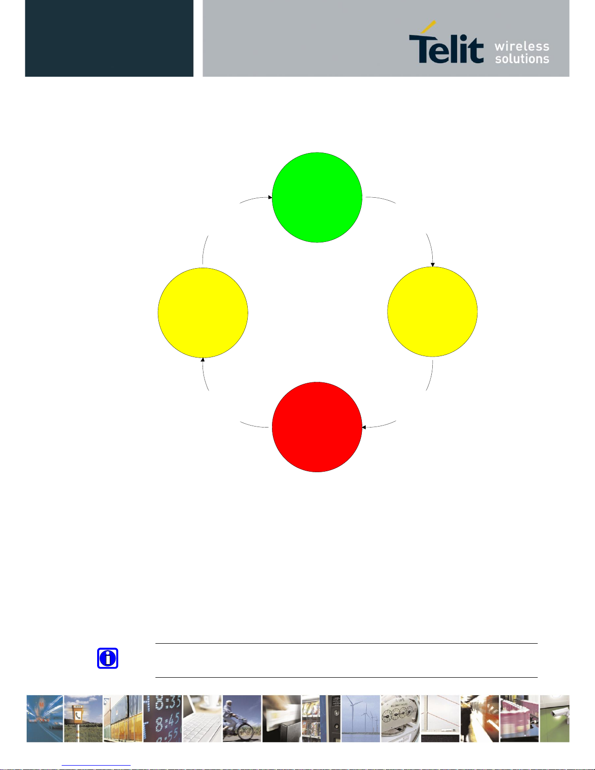
6.4. UICP Protocol States
The UICP protocol defines four states:
pending
"interface down"
- IUR-OUT# inactive
- IUC-IN# active
IUR
-
OUT
#
de
-
asserted
"interface down"
- IUR-OUT# inactive
- IUC-IN# inactive
IUC
-
IN
#
de
-
asserted
pending
"interface up"
- IUR-OUT# active
- IUC-IN# inactive
IUR
-OUT# asserted
IUC
-
IN
#
asserted
"interface up"
- IUR-OUT# active
- IUC-IN# don't care
(UART flowcontrol)
• interface up
normal operation, RTS/CTS hardware flow control is active
• pending interface down
IUR-OUT# is requested to go to "interface down" state
IUC-IN# is not confirmed
• interface down
IUR-OUT# and IUC-IN# are de-asserted in "interface down" state
and can enable MCU power saving
• pending interface up
IUR-OUT# is requested to go to "interface up" state,
IUC-IN# is not confirmed
Note: All data received before the interface up state has been achieved shall be seen as
invalid data and shall be discarded.
Page 42

BlueMod+S42/Central Software User Guide
1VV0301318 Rev. 3 – 2018-08-31
Reproduction forbidden without written authorization from Telit Communications S.p.A.- All Rights Reserved. Page 42 of 66
6.4.1. Drive from "interface up" to "interface down" State
Once a de-asserted IUR-OUT# signal of the initiator is detected by the acceptor, the acceptor
shall confirm that signal by de-asserting its IUC-OUT# signal which is connected to the IUCIN# signal of the initiator.
After the initiator detects a de-asserted IUC-IN# signal both devices go into "interface down"
state and can enable MCU power saving mechanisms.
During MCU power saving, the MCU can switch off the UART but shall be able to detect an
IUR# assert.
UICP State interface up pending interface down interface down
IUR-OUT#
IUC-IN#
RTS/CTS UART Hardware flowcontrol
UART-TXD data
t1 t2
de-asserted
asserted
de-asserted
asserted
t1 >= 100ms (see this chapter)
t2 < 1s
Page 43

BlueMod+S42/Central Software User Guide
1VV0301318 Rev. 3 – 2018-08-31
Reproduction forbidden without written authorization from Telit Communications S.p.A.- All Rights Reserved. Page 43 of 66
6.4.2. Drive from "interface down" to "interface up" State
To initiate the state change from "interface down" state to "interface up" state the initiator shall
assert the IUR-OUT# signal.
The acceptor confirms the IUR-IN# signal with asserting its IUC-OUT# signal which is
connected to the IUC-IN# signal of the initiator.
Once the acceptor detects the assert of the IUR-OUT# signal from the initiator, it can disable
MCU power saving mechanisms but shall ensure the UART is ready to receive data before it
confirms asserting its IUC-OUT# signal which is connected to the IUC-IN# signal of the
initiator.
Once the initiator detects the assert of the IUC-IN# signal of the acceptor, the in initiator can
send data to the acceptor.
UICP State interface uppending interface upinterface down
IUR-OUT#
IUC-IN# RTS/CTS UART Hardware flowcontrol
UART-TXD data
t2
asserted
de-asserted
de-asserted
asserted
Page 44

BlueMod+S42/Central Software User Guide
1VV0301318 Rev. 3 – 2018-08-31
Reproduction forbidden without written authorization from Telit Communications S.p.A.- All Rights Reserved. Page 44 of 66
6.5. Example of UICP Usage
The following examples show the state change between the BlueMod+S42/Central and the host.
The scenario here might be that both devices use the "interface down" state to drive the MCU
into some kind of power saving mode that allows to "wake up" the MCU with external GPIO
signals.
6.5.1. State Change from "interface up" to "interface down"
Host and BlueMod+S42/Central are in the state “interface up” and exchange bidirectional data.
After the host has send all data and is idle for t1 in its Tx direction it signals the
BlueMod+S42/Central that it is allowed to go to “interface down” state by de-asserting IUROUT# signal.
Parallel to that UICP signaling from host to BlueMod+S42/Central the BlueMod+S42/Central
has send all data as well and is idle for t1 in its Tx direction, so it signals the host that it is
allowed to go to “interface down” state by de-asserting IUR-OUT# signal.
The host and the BlueMod+S42/Central each wait for a maximum time t2 to detect the deasserted IUC-IN# signal. After receiving this input change via the IUC-IN# signal both devices
may change from state “pending interface down” to state “interface down”.
Both UICP signaling sequences proceed in parallel until host and BlueMod+S42/Central
interfaces are in “interface down” state.
IUR-OUT#
IUR-IN#
IUC-OUT#
(UART-RTS)
IUC-IN#
(UART-CTS)
UART-TXD
UART-RXD
BlueMod+S42 Rx-IF State
BlueMod+S42 Tx-IF State
BlueMod+S42 Signals:
IUR-IN#
IUR-OUT#
IUC-IN#
(UART-CTS)
IUC-OUT#
(UART-RTS)
UART-RXD
UART-TXD
HOST UICP Tx-IF State
HOST UICP Rx-IF State
HOST-Signals:
data
interface up pending interface down interface down
data
interface up pending interface down interface down
data flow control
data flow control
t1
t1
t2
t2
active
active
active
active
inactive
inactive
inactive
inactive
Page 45

BlueMod+S42/Central Software User Guide
1VV0301318 Rev. 3 – 2018-08-31
Reproduction forbidden without written authorization from Telit Communications S.p.A.- All Rights Reserved. Page 45 of 66
6.5.2. State Change from "interface down" to "interface up"
Host and BlueMod+S42/Central are in the state “Interface down” and may have the MCU into
some kind of power saving state.
The host wants to send data to the BlueMod+S42/Central and asserts its IUR-OUT# signal.
Parallel to that UICP signaling from host to BlueMod+S42/Central the BlueMod+S42/Central
wants to send data to the host and asserts its IUR-OUT# signal as well.
The host and the BlueMod+S42/Central each wait for a maximum time t2 to detect the assertion
via the IUC-IN# signal. After receiving this input change of IUC-IN# both devices may assume
that the interface of the remote device changed from state “pending interface up” to state
“interface up”.
Both UICP signaling sequences proceed in parallel until host and BlueMod+S42/Central
interfaces are in “interface up” state and data can be exchanged bidirectional.
BlueMod+S42 Signals:
IUR-OUT#
IUR-IN#
IUC-OUT#
(UART-RTS)
IUC-IN#
(UART-CTS)
UART-TXD
UART-RXD
BlueMod+S42 Rx-IF State
BlueMod+S42 Tx-IF State
interface up
interface up
interface down
interface down
pending interface up
pending interface up
data flow control
data flow control
data
data
IUR-IN#
IUR-OUT#
IUC-IN#
(UART-CTS)
IUC-OUT#
(UART-RTS)
UART-RXD
UART-TXD
HOST UICP Tx-IF State
HOST UICP Rx-IF State
HOST- Signals:
t2
t2
inactive
active
inactive
inactive
inactive
active
Page 46
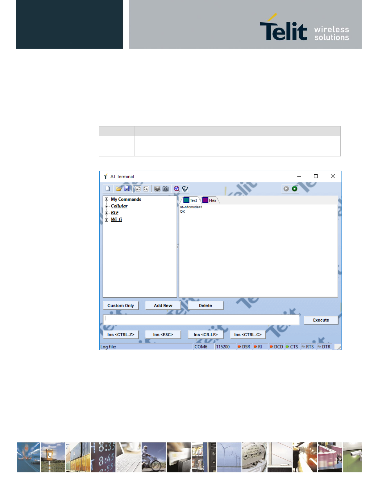
BlueMod+S42/Central Software User Guide
1VV0301318 Rev. 3 – 2018-08-31
Reproduction forbidden without written authorization from Telit Communications S.p.A.- All Rights Reserved. Page 46 of 66
7. NFC Handover
7.1. NFC Mode
The NFC mode can be activated or deactivated by using the following AT command:
AT+NFCMODE=<value>
Value
Description
0
NFC interface OFF
1
NFC interface ON
Enable the NFC Handover functionality by using the following AT command:
7.2. NFC Handover Example
Make sure NFC is available and enabled in the smartphone and move it over the NFC antenna.
The Bluetooth address will be read out and the smartphone initiates a Bluetooth pairing request
to the device of the given Bluetooth address and a Bluetooth pairing request message will
appear. Now continue with “Pair” or “Yes” to accept the Bluetooth pairing request scenario.
Page 47

BlueMod+S42/Central Software User Guide
1VV0301318 Rev. 3 – 2018-08-31
Reproduction forbidden without written authorization from Telit Communications S.p.A.- All Rights Reserved. Page 47 of 66
After the pairing request ended successfully you will find the new paired device within the
Bluetooth settings of your smartphone.
For further information regarding NFC Handover please refer to the BlueEva+S42 User Guide.
Page 48

BlueMod+S42/Central Software User Guide
1VV0301318 Rev. 3 – 2018-08-31
Reproduction forbidden without written authorization from Telit Communications S.p.A.- All Rights Reserved. Page 48 of 66
8. Firmware Upgrade
The firmware upgrade will be done locally by either
• A Telit provided firmware update tool. This is a Windows™ program that contains the
firmware and uses a PC with a serial port for the update
• Implementing the firmware update protocol on the host system or over the air.
8.1. Serial Firmware Upgrade
8.1.1. Prerequisites for Serial Firmware Upgrade
You need to have access to the UART interface of the BlueMod+S42/Central.
Serial firmware update requires at least the serial lines UART-RXD, UART-TXD, UART-
CTS#, UART-RTS# and GND.
Serial firmware update requires a UART speed of 38400 bps.
Pin BOOT0 (E-1) shall be pulled high to access the bootloader at start-up.
8.1.2. Telit IoT Updater
The firmware upgrade will be done by a Telit provided firmware update tool. This is a
Windows™ program that contains the firmware and uses a PC with a serial port for the update.
For example a firmware version V3.002 will result in the executable file
“BM+S42_v3_002_FWupdate.exe”.
The software used for the upgrade is able to run on the following Win32/Win64 platforms:
• Windows XP
• Windows Vista
• Windows 7
• Windows 8
• Windows 10
Note: Testing was carried out on Windows 10 Pro, Windows 8 Pro, Windows 7
Ultimate and XP Professional platforms; however experience suggests that the
described software runs on all XP platforms and all Windows 10 / 8 / 7 / Vista
32 and 64-bit platforms.
Page 49

BlueMod+S42/Central Software User Guide
1VV0301318 Rev. 3 – 2018-08-31
Reproduction forbidden without written authorization from Telit Communications S.p.A.- All Rights Reserved. Page 49 of 66
The program requires a PC with at least one free COM port.
The upload is processed via the serial port the device is attached to.
Before starting the update by pressing the “Update” button the device shall be reset.
• COM-Port
The COM-Port the device is attached to
• Update
Starts the update procedure
After the successful update close the software, remove the high level on pin BOOT0 and reset
the BlueMod+S42/Central.
Note: Do not disconnect the device while the update is in progress, otherwise the update
will fail and has to be repeated. In case it is not possible to update the
BlueMod+S42/Central please contact the Telit support (e-mail: ts-srd@telit.com).
Page 50

BlueMod+S42/Central Software User Guide
1VV0301318 Rev. 3 – 2018-08-31
Reproduction forbidden without written authorization from Telit Communications S.p.A.- All Rights Reserved. Page 50 of 66
8.1.3. Firmware Update Protocol on the Host System
This chapter describes the protocol layer used for firmware update over serial on the
BlueMod+S42/Central.
The table below contains the maximum possible binary firmware sizes:
Firmware variant
Maximum possible binary firmware size
V3.002
332 kBytes
Note: The actual size of each firmware binary file can be found in the firmware release
notes.
8.1.3.1. Layer Structure
The device firmware update uses the HCI Three-Wire UART Transport Layer specified in
Bluetooth 4.0 Core Specification. Instead of HCI frames, four different DFU packets are sent
to the BlueMod+S42/Central over the UART serial interface using this transport.
8.1.3.2. DFU Packet Layer
There are four different packet types in this layer. The packet type is an unsigned 32 bit integer
in LSB first order.
1. Start packet 0x00000003
2. Init packet 0x00000001
3. Application data packet 0x00000004
4. Stop packet 0x00000005
DFU packet layer
Three wire UART
packet layer
SLIP layer
UART
Page 51

BlueMod+S42/Central Software User Guide
1VV0301318 Rev. 3 – 2018-08-31
Reproduction forbidden without written authorization from Telit Communications S.p.A.- All Rights Reserved. Page 51 of 66
Start packet
With the “Start packet” the DFU bootloader is informed about the kind of update and the length
of the binary image. The length of the image is an unsigned 32 bit integer in LSB first order. It
is length of the file with the “.bin” extension in the Telit delivery package (zip file). For a binary
application with image size of 17,336 bytes (0x000043B8), the packet is coded as:
Byte1
Byte2
Byte3
Byte4
Byte5
Byte6
Byte7
Byte8
0x03
0x00
0x00
0x00
0x04
0x00
0x00
0x00
1.
Byte9
Byte10
Byte11
Byte12
Byte13
Byte14
Byte15
Byte16
0x00
0x00
0x00
0x00
0x00
0x00
0x00
0x00
2.
Byte17
Byte18
Byte19
Byte20
0xB8
0x43
0x00
0x00
Init packet
The init packet contains information about the application that is transferred. The DFU
bootloader checks this information to determine if the image is valid for the device. Please use
as contents only the init packet provided by Telit. The data starting with “Device type” and
ending with “CRC of the image that will be transferred” (see the Nordic documentation) is
provided by Telit in the Telit delivery package (zip file). It is the contents of the file with the
extension “.dat”. The binary application to load with the data packets is the file with the “.bin”
extension.
The init packet is coded as:
Byte1
Byte2
Byte3
Byte4
Byte5 up to Byte n
Byte n+1
Byte n+2
0x01
0x00
0x00
0x00
Contents of the “.dat”
file. The length is
variable.
0x00
0x00
Required waiting
After accepting the init packet the bootloader prepares (erases) the internal flash memory to
accommodate the new image. The bootloader accepts no data packets during this time. Please
wait 10 seconds before sending the first data packet.
Application data packet
With the Application data packet the binary application image is transferred to the
BlueMod+S42/Central. The binary application to load with the data packets is the file with the
“.bin” extension in the Telit delivery package (zip file). The maximum packet size is 512 bytes
of data + header per packet. Each packet is coded:
Byte1
Byte2
Byte3
Byte4
Byte 5 … up to Byte 516
0x04
0x00
0x00
0x00
Max 512 bytes of binary application data
Page 52

BlueMod+S42/Central Software User Guide
1VV0301318 Rev. 3 – 2018-08-31
Reproduction forbidden without written authorization from Telit Communications S.p.A.- All Rights Reserved. Page 52 of 66
Stop packet
When the Application image has been transferred to the BlueMod+S42/Central boot loader the
image must be activated. The stop packet will inform the boot loader that transferring of the
image has completed and the application can be started. The packet is coded as:
Byte1
Byte2
Byte3
Byte4
0x05
0x00
0x00
0x00
8.1.3.3. Three Wire UART Packet Layer
Every packet that is sent over the Three-Wire UART Transport Layer has a packet header. It
also has 16 bit CCITT-CRC at the end of the payload.
Each transport packet will contain one higher layer packet. A transport packet consists of a
Packet Header of 4 octets, a payload of 4 to 516 octets, and a 16 bit CCITT-CRC.
The Packet header consists of a Sequence Number of 3 bits, an Acknowledge Number of 3 bits,
a Data Integrity Check Present bit, a Reliable Packet bit, a Packet Type of 4 bits, a Payload
Length of 12 bits and a 8 bit Header Checksum.
The used Packet Type is vendor specific (0xe).
LSB MSB
4 Octets
1.. 156 Octets
2 Octets
Packet Header
DFU packet layer
16 bit CCITT-CRC
The detailed format description of the used packet header can be found in Bluetooth 4.0 Core
Specification.
For a detailed description of the procedural requirements of this protocol have a look in the
Bluetooth 4.0 Core Specification, chapter “Three-Wire UART Transport Layer”.
8.1.3.4. SLIP Layer
The SLIP layer performs octet stuffing on the octets entering the layer so that specific octet
codes which may occur in the original data do not occur in the resultant stream.
The SLIP layer places octet 0xC0 at the start and end of every packet it transmits.
Any occurrence of 0xC0 in the original packet is changed to the sequence 0xDB 0xDC before
being transmitted. Any occurrence of 0xDB in the original packet is changed to the sequence
0xDB 0xDD before being transmitted. These sequences, 0xDB 0xDC and 0xDB 0xDD are
SLIP escape sequences.
For a detailed description of this protocol have a look in the Bluetooth 4.0 Core Specification,
chapter “Three-Wire UART Transport Layer”.
Page 53

BlueMod+S42/Central Software User Guide
1VV0301318 Rev. 3 – 2018-08-31
Reproduction forbidden without written authorization from Telit Communications S.p.A.- All Rights Reserved. Page 53 of 66
8.2. Firmware Update over The Air (OTA)
The BlueMod+S42/Central supports firmware over the air update. The firmware update over
the air can be performed by using the Nordic nRF ToolBox app available for iOS and Android
or by using the Nordic Master Control Panel and the corresponding Nordic Bluetooth hardware.
The firmware over the air update in the BlueMod+S42/Central will be enabled with the
commands below:
1. AT+DFUMODE=2
2. AT+DFUSTART
After sending the AT+DFUSTART command the BlueMod+S42/Central is visible in the air as
“BM+S_DFU” (name configured with command AT+DFUNAME) for a time period of 2
minutes. If no firmware update is performed during this time the BlueMod+S42/Central will
continue with normal operation.
The following chapter describes the firmware over the air update by using the Nordic nRF
Toolbox app on Android.
Page 54

BlueMod+S42/Central Software User Guide
1VV0301318 Rev. 3 – 2018-08-31
Reproduction forbidden without written authorization from Telit Communications S.p.A.- All Rights Reserved. Page 54 of 66
8.2.1. Firmware Update Over The Air using Nordic nRF Toolbox on
Android
Make sure the BlueMod+S42/Central has already activated the firmware over the air update.
Open the nRF ToolBox app on the smartphone and choose “DFU“.
Press the button “SELECT FILE”.
Page 55

BlueMod+S42/Central Software User Guide
1VV0301318 Rev. 3 – 2018-08-31
Reproduction forbidden without written authorization from Telit Communications S.p.A.- All Rights Reserved. Page 55 of 66
Select file type “Distribution packet (ZIP)”.
Search via file manager for the firmware package which was previously copied to the
smartphone (e.g BMS42_Central_V3_010_FWupdate_OTA.zip in the example below).
Page 56

BlueMod+S42/Central Software User Guide
1VV0301318 Rev. 3 – 2018-08-31
Reproduction forbidden without written authorization from Telit Communications S.p.A.- All Rights Reserved. Page 56 of 66
Press the button “SELECT DEVICE” and select the “BM+S_DFU” from the list of available
devices.
Press the “UPLOAD” button to upload the firmware package over the air to the
BlueMod+S42/Central.
After the file was uploaded successfully the BlueMod+S42/Central will start with the new
firmware.
Page 57

BlueMod+S42/Central Software User Guide
1VV0301318 Rev. 3 – 2018-08-31
Reproduction forbidden without written authorization from Telit Communications S.p.A.- All Rights Reserved. Page 57 of 66
9. System OFF Mode
The BlueMod+S42/Central supports the possibility to set the module into low power mode
during the time the module is not used with the AT+SYSTEMOFF command.
The BlueMod+S42/Central will restart on activity at the GPIO input lines UART-RTS#, IURIN# or GPIO[4].
The host controller can use the IOA pin (GPIO[8]) to monitor the system status. Please also
verify the configuration of the AT+IOACFG parameter.
It is also possible to monitor the UART flow control line UART-RTS#.
9.1. Using System OFF Mode for Terminal I/O
The following example will list the communication between the host controller and the
BlueMod+S42/Central using the integrated Terminal I/O profile.
To set the BlueMod+S42/Central into the low power mode the host controller needs to send the
AT+SYSTEMOFF command.
The BlueMod+S42/Central will respond “OK” before changing into low power mode.
To activate the BlueMod+S42/Central from low power mode the host controller needs to
activate one of the following GPIO lines: UART-RTS#, IUR-IN#, GPIO[4]
The module detects the GPIO change and starts the firmware.
After the firmware is started the host can continue the UART communication.
An incoming call is reported with RING and CONNECT.
Page 58

BlueMod+S42/Central Software User Guide
1VV0301318 Rev. 3 – 2018-08-31
Reproduction forbidden without written authorization from Telit Communications S.p.A.- All Rights Reserved. Page 58 of 66
Page 59

BlueMod+S42/Central Software User Guide
1VV0301318 Rev. 3 – 2018-08-31
Reproduction forbidden without written authorization from Telit Communications S.p.A.- All Rights Reserved. Page 59 of 66
10. LE Connection Parameters
This chapter describes the kind of creating a BLE connection from the central device to the
peripheral device include the usage of the LE connection parameters.
10.1. Create a Bluetooth Low Energy Connection
In a typical Bluetooth Low Energy system, the peripheral device advertises with specific data
letting any central device know that it is a connectable device. This advertisement contains the
device address, and can contain some additional data as well, such as the device name. The
central device, upon receiving the advertisement, sends a “scan request” to the peripheral. The
peripheral responds with a “scan response”. This is the process of device discovery, in that the
central device is now aware of the peripheral device, and knows that it can form a connection
with it. The central device can then send out a request to establish a link with the peripheral
device. A connection request contains a few connection parameters:
• Connection Interval
In a BLE connection between two devices, a frequency-hopping scheme is used, in that the
two devices each send and receive data from one another on a specific channel, then “meet”
at a new channel (the link layer of the BLE stack handles the channel switching) at a specific
amount of time later. This “meeting” where the two devices send and receive data is known
as a “connection event”. Even if there is no application data to be sent or received, the two
devices will still exchange link layer data to maintain the connection. The connection
interval is the amount of time between two connection events, in units of 1.25ms. The
connection interval can range from a minimum value of 6 (7.5ms) to a maximum of 3200
(4.0s).
The BlueMod+S42/Central uses the configuration command AT+LECONINTMIN and
AT+LECONINTMAX to set these predefined values of the connection interval.
• Slave Latency
This parameter gives the slave (peripheral) device the option of skipping a number of
connection events. This gives the peripheral device some flexibility, in that if it does not
have any data to send it can choose to skip connection events and stay asleep, thus providing
some power savings. The decision is up to the peripheral device.
The slave latency value represents the maximum number of events that can be skipped. It
can range from a minimum value of 0 (meaning that no connection events can be skipped)
to a maximum of 499; however the maximum value must not make the effective connection
interval (see below) greater than 32.0s.
The BlueMod+S42/Central uses the configuration command AT+LESLAVELAT to set the
predefined slave latency timeout value.
Page 60

BlueMod+S42/Central Software User Guide
1VV0301318 Rev. 3 – 2018-08-31
Reproduction forbidden without written authorization from Telit Communications S.p.A.- All Rights Reserved. Page 60 of 66
• Supervision Timeout
This is the maximum amount of time between two successful connection events. If this
amount of time passes without a successful connection event, the device is to consider the
connection lost, and return to an unconnected state. This parameter value is represented in
units of 10ms. The supervision timeout value can range from a minimum of 10 (100ms) to
3200 (32.0s). In addition, the timeout must be larger than the effective connection interval
(explained below).
The BlueMod+S42/Central calculates this timeout value as followed:
(Slave latency value + 1) x 2 x Connection interval time x 2
Limitations of calculated “Connection supervision timeout”:
calculated value: +/- 10ms
minimum value: >= 100ms
maximum value: <= 32s
10.2. Optimize the Connection Interval from Slave by using
the Slave Latency
The “effective connection interval” is equal to the amount of time between two connection
events, assuming that the slave skips the maximum number of possible events if slave latency
is allowed (the effective connection interval is equal to the actual connection interval if slave
latency is set to zero). It can be calculated using the formula:
Effective Connection Interval = (Connection Interval) * ( 1 + (Slave Latency) )
Take the following example:
Connection Interval: 80 (80 * 1.25ms =100ms)
Slave Latency: 4
Effective Connection Interval: (100ms) * ( 1 + 4 ) = 500ms
This tells us that in a situation in which no data is being sent from the slave to the master, the
slave will only transmit during a connection event once every 500ms.
Page 61

BlueMod+S42/Central Software User Guide
1VV0301318 Rev. 3 – 2018-08-31
Reproduction forbidden without written authorization from Telit Communications S.p.A.- All Rights Reserved. Page 61 of 66
10.3. Identify the Required Connection Interval
Different applications may require different connection intervals. The advantage of having a
very long connection interval is that significant power is saved, since the device can sleep most
of the time between connection events. The disadvantage is that if a device has data that it needs
to send, it must wait until the next connection event.
The advantage of having a very short connection interval is that there is more opportunity for
data to be sent or received, as the two devices will connect more frequently. The disadvantage
is that more power will be consumed, since the device is frequently waking up for connection
events.
In many applications, the slave will skip the maximum number of connection events. Therefore
it is useful to consider the effective connection interval when selecting the connection
parameters. Selecting the correct group of connection parameters plays an important role in
power optimization of the BLE device. The following list gives a general summary of the tradeoffs in connection parameter settings:
Reducing the connection interval will:
• Increase the power consumption for both devices
• Increase the throughput in both directions
• Reduce the amount of time that it takes for data to be sent in either direction
Increasing the connection interval will:
• Reduce the power consumption for both devices
• Reduce the throughput in both directions
• Increase the amount of time that it takes for data to be sent in either direction
Reducing the slave latency (or setting it to zero) will:
• Increase the power consumption for the peripheral device
• Reduce the amount of time that it takes for data sent from the central device to be
received by the peripheral device
Increasing the slave latency will:
• Reduce power consumption for the peripheral during periods when the peripheral has no
data to send to the central device
• Increase the amount of time that it takes for data sent from the central device to be
received by the peripheral device
Page 62

BlueMod+S42/Central Software User Guide
1VV0301318 Rev. 3 – 2018-08-31
Reproduction forbidden without written authorization from Telit Communications S.p.A.- All Rights Reserved. Page 62 of 66
10.4. Update the Connection Parameters
In some cases, the central device will request a connection with a peripheral device containing
connection parameters that are unfavorable to the peripheral device. In other cases, a peripheral
device might have the desire to change parameters in the middle of a connection, based on the
peripheral application. The peripheral device can request the central device to change the
connection settings by sending a “Connection Parameter Update Request”.
This request contains four parameters:
• minimum connection interval
• maximum connection interval
• slave latency
• timeout
These values represent the parameters that the peripheral device desires for the connection (the
connection interval is given as a range). When the central device receives this request, it has
the option of accepting or rejecting the new parameters.
The BlueMod+S42/Central uses the configuration command AT+LECONPARAM to initiate
the “Connection Parameter Update Request” message or report the current connection
parameter set.
Changing the connection parameter set using the AT+LECONPARAM command effects in the
current connection only. After disconnecting the GATT connection the BlueMod+S42/Central
uses the configured connection parameters (AT+LECONINTMIN, AT+LECONINTMAX,
AT+SLAVELAT, and the calculated connection timeout) for further connections.
To automatically signal a “Connection Parameter Update Request” the BlueMod+S42/Central
uses the command “AT+LECPEVENT=1” that enables the reporting of connection parameter
set changes to the local serial interface.
The BlueMod+S42/Central accepts all valid “Connection Parameter Update Requests” values
of a peripheral device in order to save power consumption for the peripheral device.
10.5. Connection Examples of Different Use Cases
The following examples will demonstrate Bluetooth LE GATT connections between different
devices to demonstrate the initial connection parameter set and the possibility to monitor or
change these connection parameter set.
Page 63

BlueMod+S42/Central Software User Guide
1VV0301318 Rev. 3 – 2018-08-31
Reproduction forbidden without written authorization from Telit Communications S.p.A.- All Rights Reserved. Page 63 of 66
10.5.1. Central Side Initiates a GATT Connection
Page 64

BlueMod+S42/Central Software User Guide
1VV0301318 Rev. 3 – 2018-08-31
Reproduction forbidden without written authorization from Telit Communications S.p.A.- All Rights Reserved. Page 64 of 66
10.5.2. Central Side Changed Initial Connection Parameter
Page 65
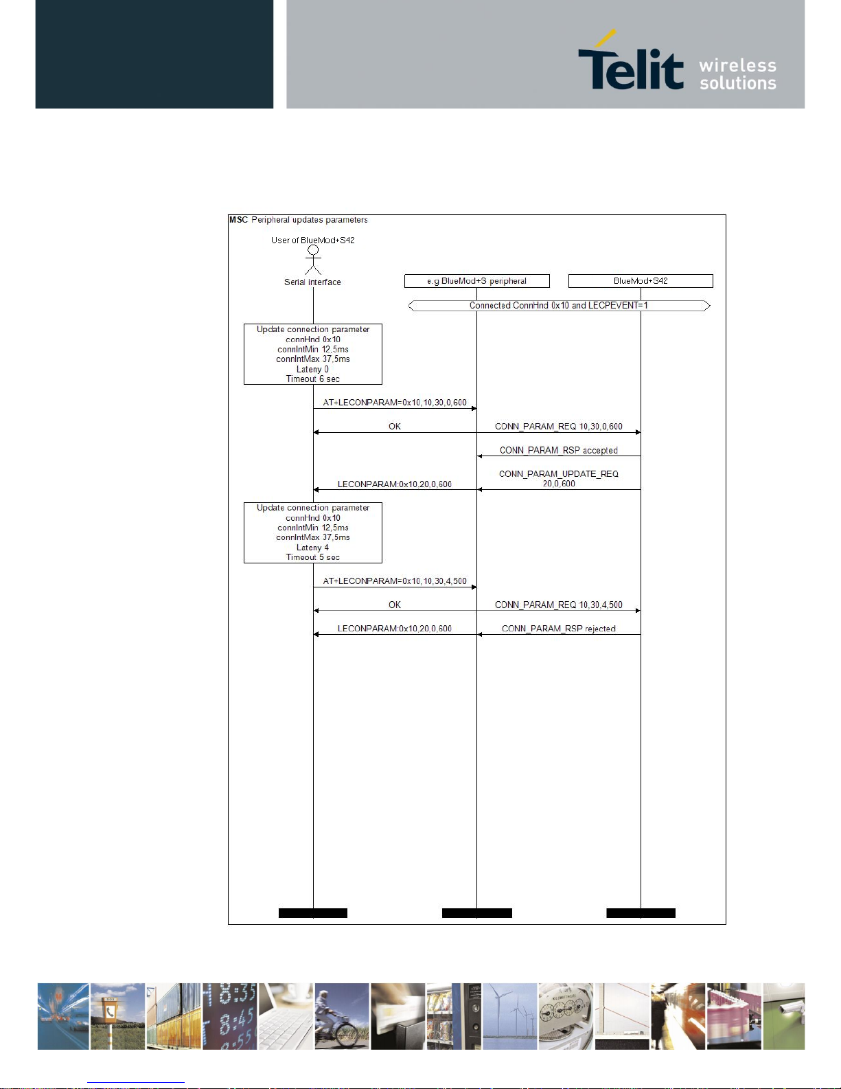
BlueMod+S42/Central Software User Guide
1VV0301318 Rev. 3 – 2018-08-31
Reproduction forbidden without written authorization from Telit Communications S.p.A.- All Rights Reserved. Page 65 of 66
10.5.3. Peripheral Side Create a Connection Parameter Update
Request
Page 66

BlueMod+S42/Central Software User Guide
1VV0301318 Rev. 3 – 2018-08-31
Reproduction forbidden without written authorization from Telit Communications S.p.A.- All Rights Reserved. Page 66 of 66
11. Document History
Revision
Date
Changes
r0
2016-08-19
First issue
r1
2016-10-05
Added new values 3,4 of AT+LETIO command,
Added new chapter LE Secure Connections,
Corrected value of AT+BIOCAP in connection example
Terminal I/O "Passkey entry"
r2
2018-02-02
Replaced TeraTerm by Telit AT Controller
Replaced BlueMod+S42 Updater by IoT Updater
Added Terminal IO Utility app for Android
Adopted the I/O capabilities table to Bluetooth 4.2
r3
2018-08-31
Added Bluetooth address type (tx) in I/O capabilities matrix
 Loading...