

Telit Communications S p A XE866A1NA User Manual

Mod.0818 2017-01 Rev.0
LE866
Hardware Design Guide
1VV0301355 Rev. 3 – 2017-09-07

LE866 Hardware Design Guide
SPECIFICATIONS ARE SUBJECT TO CHANGE WITHOUT NOTICE
NOTICE
While reasonable efforts have been made to assure the accuracy of this document, Telit
assumes no liability resulting from any inaccuracies or omissions in this document, or from
use of the information obtained herein. The information in this document has been carefully
checked and is believed to be reliable. However, no responsibility is assumed for
inaccuracies or omissions. Telit reserves the right to make changes to any products
described herein and reserves the right to revise this document and to make changes from
time to time in content hereof with no obligation to notify any person of revisions or changes.
Telit does not assume any liability arising out of the application or use of any product,
software, or circuit described herein; neither does it convey license under its patent rights
or the rights of others.
It is possible that this publication may contain references to, or information about Telit
products (machines and programs), programming, or services that are not announced in
your country. Such references or information must not be construed to mean that Telit
intends to announce such Telit products, programming, or services in your country.
COPYRIGHTS
This instruction manual and the Telit products described in this instruction manual may be,
include or describe copyrighted Telit material, such as computer programs stored in
semiconductor memories or other media. Laws in the Italy and other countries preserve for
Telit and its licensors certain exclusive rights for copyrighted material, including the
exclusive right to copy, reproduce in any form, distribute and make derivative works of the
copyrighted material. Accordingly, any copyrighted material of Telit and its licensors
contained herein or in the Telit products described in this instruction manual may not be
copied, reproduced, distributed, merged or modified in any manner without the express
written permission of Telit. Furthermore, the purchase of Telit products shall not be deemed
to grant either directly or by implication, estoppel, or otherwise, any license under the
copyrights, patents or patent applications of Telit, as arises by operation of law in the sale
of a product.
COMPUTER SOFTWARE COPYRIGHTS
The Telit and 3rd Party supplied Software (SW) products described in this instruction manual
may include copyrighted Telit and other 3rd Party supplied computer programs stored in
semiconductor memories or other media. Laws in the Italy and other countries preserve for
Telit and other 3rd Party supplied SW certain exclusive rights for copyrighted computer
programs, including the exclusive right to copy or reproduce in any form the copyrighted
computer program. Accordingly, any copyrighted Telit or other 3rd Party supplied SW
computer programs contained in the Telit products described in this instruction manual may
not be copied (reverse engineered) or reproduced in any manner without the express written
permission of Telit or the 3rd Party SW supplier. Furthermore, the purchase of Telit products
shall not be deemed to grant either directly or by implication, estoppel, or otherwise, any
license under the copyrights, patents or patent applications of Telit or other 3rd Party
supplied SW, except for the normal non-exclusive, royalty free license to use that arises by
operation of law in the sale of a product.
1VV0301355 Rev. 3 Page 2 of 90 2017-09-07

LE866 Hardware Design Guide
USAGE AND DISCLOSURE RESTRICTIONS
I. License Agreements
The software described in this document is the property of Telit and its licensors. It is
furnished by express license agreement only and may be used only in accordance with the
terms of such an agreement.
II. Copyrighted Materials
Software and documentation are copyrighted materials. Making unauthorized copies is
prohibited by law. No part of the software or documentation may be reproduced,
transmitted, transcribed, stored in a retrieval system, or translated into any language or
computer language, in any form or by any means, without prior written permission of Telit
III. High Risk Materials
Components, units, or third-party products used in the product described herein are NOT
fault-tolerant and are NOT designed, manufactured, or intended for use as on-line control
equipment in the following hazardous environments requiring fail-safe controls: the
operation of Nuclear Facilities, Aircraft Navigation or Aircraft Communication Systems, Air
Traffic Control, Life Support, or Weapons Systems (High Risk Activities”). Telit and its
supplier(s) specifically disclaim any expressed or implied warranty of fitness for such High
Risk Activities.
IV. Trademarks
TELIT and the Stylized T Logo are registered in Trademark Office. All other product or
service names are the property of their respective owners.
V. Third Party Rights
The software may include Third Party Right software. In this case you agree to comply with
all terms and conditions imposed on you in respect of such separate software. In addition
to Third Party Terms, the disclaimer of warranty and limitation of liability provisions in this
License shall apply to the Third Party Right software.
TELIT HEREBY DISCLAIMS ANY AND ALL WARRANTIES EXPRESS OR IMPLIED
FROM ANY THIRD PARTIES REGARDING ANY SEPARATE FILES, ANY THIRD PARTY
MATERIALS INCLUDED IN THE SOFTWARE, ANY THIRD PARTY MATERIALS FROM
WHICH THE SOFTWARE IS DERIVED (COLLECTIVELY “OTHER CODE”), AND THE
USE OF ANY OR ALL THE OTHER CODE IN CONNECTION WITH THE SOFTWARE,
INCLUDING (WITHOUT LIMITATION) ANY WARRANTIES OF SATISFACTORY
QUALITY OR FITNESS FOR A PARTICULAR PURPOSE.
NO THIRD PARTY LICENSORS OF OTHER CODE SHALL HAVE ANY LIABILITY FOR
ANY DIRECT, INDIRECT, INCIDENTAL, SPECIAL, EXEMPLARY, OR CONSEQUENTIAL
DAMAGES (INCLUDING WITHOUT LIMITATION LOST PROFITS), HOWEVER CAUSED
AND WHETHER MADE UNDER CONTRACT, TORT OR OTHER LEGAL THEORY,
ARISING IN ANY WAY OUT OF THE USE OR DISTRIBUTION OF THE OTHER CODE
OR THE EXERCISE OF ANY RIGHTS GRANTED UNDER EITHER OR BOTH THIS
LICENSE AND THE LEGAL TERMS APPLICABLE TO ANY SEPARATE FILES, EVEN IF
ADVISED OF THE POSSIBILITY OF SUCH DAMAGES.
1VV0301355 Rev. 3 Page 3 of 90 2017-09-07

LE866 Hardware Design Guide
LE866-SV1
LE866A1-NA
LE866A1-KK
LE866A1-JS
LE866A1-KS
APPLICABILITY TABLE
PRODUCTS
1VV0301355 Rev. 3 Page 4 of 90 2017-09-07
LE866 Hardware Design Guide
Contents
NOTICE 2
COPYRIGHTS ................................................................................................ 2
COMPUTER SOFTWARE COPYRIGHTS ...................................................... 2
USAGE AND DISCLOSURE RESTRICTIONS ............................................... 3
I. License Agreements ..................................................................... 3
II. Copyrighted Materials ................................................................... 3
III. High Risk Materials ....................................................................... 3
IV. Trademarks .................................................................................. 3
V. Third Party Rights ......................................................................... 3
APPLICABILITY TABLE ................................................................................ 4
CONTENTS .................................................................................................... 5
1. INTRODUCTION .......................................................................... 9
Scope ................................ ........................................................... 9
Audience....................................................................................... 9
Contact Information, Support ........................................................ 9
Text Conventions ........................................................................ 10
Related Documents .................................................................... 11
2. GENERAL PRODUCT DESCRIPTION ...................................... 12
Overview..................................................................................... 12
Product Variants and Frequency Bands ...................................... 12
Target market ................................ ............................................. 13
Main features .............................................................................. 13
TX Output Power ........................................................................ 14
RX Sensitivity ............................................................................. 14
Mechanical specifications ........................................................... 15
2.7.1. Dimensions ................................................................................. 15
2.7.2. Weight ........................................................................................ 15
Temperature range ..................................................................... 15
3. PINS ALLOCATION ................................................................... 16
Pin-out ........................................................................................ 16
LGA Pads Layout ........................................................................ 23
1VV0301355 Rev. 3 Page 5 of 90 2017-09-07
LE866 Hardware Design Guide
4. POWER SUPPLY ....................................................................... 24
Power Supply Requirements ....................................................... 24
Power Consumption ................................................................... 25
General Design Rules ................................................................. 26
4.3.1. Electrical Design Guidelines ....................................................... 26
4.3.1.1. +5V Source Power Supply Design Guidelines ............................ 26
4.3.2. +12V Source Power Supply Design Guidelines .......................... 28
4.3.2.1. Battery Source Power Supply Design Guidelines ........................ 29
4.3.3. Thermal Design Guidelines ......................................................... 30
4.3.4. Power Supply PCB layout Guidelines ......................................... 31
RTC Bypass out .......................................................................... 33
VAUX Power Output ................................................................... 34
VDDIO_IN Power Input ............................................................... 35
3GPP Power Saving Mode (PSM) .............................................. 36
5. DIGITAL SECTION .................................................................... 37
Logic Levels ................................................................................ 37
Power On.................................................................................... 38
Power Off.................................................................................... 40
Unconditional Restart.................................................................. 41
Fast System Turn Off .................................................................. 44
5.5.1. Fast Turn Off by Hardware ......................................................... 44
5.5.2. Fast Shut Down by Software....................................................... 45
Communication ports .................................................................. 46
5.6.1. USB 2.0 HS ................................................................................ 46
5.6.2. Serial Ports ................................................................................. 47
5.6.2.1. MODEM SERIAL PORT 1 (USIF0) ............................................. 47
5.6.2.2. MODEM SERIAL PORT 2 (USIF1) ............................................. 49
5.6.2.3. RS232 LEVEL TRANSLATION ................................................... 49
General purpose I/O ................................................................... 51
5.7.1. Using a GPIO as INPUT ............................................................. 52
5.7.2. Using a GPIO as OUTPUT ......................................................... 53
5.7.3. Indication of network service availability ..................................... 53
5.7.4. SIMIN Detection .......................................................................... 54
External SIM Holder .................................................................... 55
ADC Converter ........................................................................... 55
DAC Converter ........................................................................... 56
5.10.1. Enabling DAC ............................................................................. 56
1VV0301355 Rev. 3 Page 6 of 90 2017-09-07
LE866 Hardware Design Guide
5.10.2. LOW Pass filter Example ............................................................ 57
6. RF SECTION .............................................................................. 58
Antenna requirements................................................................. 58
6.1.1. Main Antenna ............................................................................. 58
6.1.2. PCB Design guidelines ............................................................... 59
6.1.3. PCB Guidelines in case of FCC Certification .............................. 60
6.1.3.1. Transmission line design ............................................................ 60
6.1.3.2. Transmission Line Measurements .............................................. 61
6.1.3.3. Antenna Installation Guidelines ................................................... 63
Second Antenna requirements .................................................... 64
6.2.1. Single Antenna Operation ........................................................... 65
7. AUDIO SECTION ....................................................................... 66
Electrical Characteristics ............................................................. 66
Codec examples ......................................................................... 66
8. MECHANICAL DESIGN ............................................................. 67
9. APPLICATION PCB DESIGN .................................................... 68
Footprint ..................................................................................... 68
PCB pad design .......................................................................... 69
PCB pad dimensions .................................................................. 69
Stencil ......................................................................................... 70
Solder paste ............................................................................... 71
Solder Reflow ................................ ............................................. 71
10. PACKAGING .............................................................................. 73
Tray ............................................................................................ 73
Moisture sensitivity ..................................................................... 75
11. CONFORMITY ASSESSMENT ISSUES .................................... 76
Approvals.................................................................................... 76
Declaration of Conformity ........................................................... 76
FCC certificates .......................................................................... 76
IC/ISED certificates ..................................................................... 76
FCC/ISED Regulatory notices LE866-SV1 .................................. 76
FCC/ISED Regulatory notices LE866A1-NA ............................... 80
12. SAFETY RECOMMENDATIONS................................................ 83
READ CAREFULLY .................................................................... 83
13. REFERENCE TABLE OF RF BANDS CHARACTERISTICS ..... 84
1VV0301355 Rev. 3 Page 7 of 90 2017-09-07

LE866 Hardware Design Guide
14. ACRONYMS ............................................................................... 87
15. DOCUMENT HISTORY .............................................................. 89
1VV0301355 Rev. 3 Page 8 of 90 2017-09-07

LE866 Hardware Design Guide
1. INTRODUCTION
Scope
This document introduces the Telit LE866 modules and presents possible and
recommended hardware solutions for developing a product based on this module. All the
features and solutions detailed in this document are applicable to all LE866 variants, where
LE866 refers to the variants listed in the applicability table.
Obviously, this document cannot embrace every hardware solution or every product that
can be designed. Where the suggested hardware configurations need not be considered
mandatory, the information given should be used as a guide and a starting point for properly
developing your product with the Telit module.
Audience
This document is intended for Telit customers, especially system integrators, about to
implement their applications using the Telit module.
Contact Information, Support
For general contact, technical support services, technical questions and report
documentation errors contact Telit Technical Support at:
TS-EMEA@telit.com
TS-AMERICAS@telit.com
TS-APAC@telit.com
TS-SRD@telit.com
Alternatively, use:
http://www.telit.com/support
For detailed information about where you can buy the Telit modules or for recommendations
on accessories and components visit:
http://www.telit.com
Our aim is to make this guide as helpful as possible. Keep us informed of your comments
and suggestions for improvements.
Telit appreciates feedback from the users of our information.
1VV0301355 Rev. 3 Page 9 of 90 2017-09-07
LE866 Hardware Design Guide
Danger – This information MUST be followed or catastrophic
equipment failure or bodily injury may occur.
Caution or Warning – Alerts the user to important points about
integrating the module, if these points are not followed, the module and
end user equipment may fail or malfunction.
Tip or Information – Provides advice and suggestions that may be
useful when integrating the module.
Text Conventions
All dates are in ISO 8601 format, i.e. YYYY-MM-DD.
1VV0301355 Rev. 3 Page 10 of 90 2017-09-07

LE866 Hardware Design Guide
Related Documents
SIM Holder Design Guides, 80000NT10001A
LE866 AT Commands Reference Guide, 80471ST10691A
Telit EVK2 User Guide, 1vv0300704
xE866 Interfaces User Guide, 1vv0301260
1VV0301355 Rev. 3 Page 11 of 90 2017-09-07

LE866 Hardware Design Guide
Product
2G Band (MHz)
3G Band (MHz)
4G Band (MHz)
Region
LE866-SV1
B4 (AWS1700)
B13 (700)
North America
Verizon
LE866A1-NA
B2 (1900)
B4 (AWS1700)
B12 (700)
North America
AT&T
LE866A1-KK
B3 (1800)
B8 (900)
Korea
KT
LE866A1-KS
B3 (1800)
B5 (850)
Korea
SKT
LE866A1-JS
B1 (2100)
B8 (900)
Japan
Softbank
2. GENERAL PRODUCT DESCRIPTION
Overview
LE866 is Telit’s new LTE series for IoT applications.
In its most basic use case, LE866 can be applied as a wireless communication front-end
for telematics products, offering mobile communication features to an external host CPU
through its interfaces.
Product Variants and Frequency Bands
All LE866 variants are single mode LTE.
Different bands combinations are available:
Refer to Chapter 13 for details information about frequencies and bands.
1VV0301355 Rev. 3 Page 12 of 90 2017-09-07

LE866 Hardware Design Guide
Function
Features
Modem
Multi-RAT cellular modem for voice and data communication
o LTE FDD Cat1 (10/5Mbps DL/UL).
o Carrier aggregation is not supported
SMS support (text and PDU)
Alarm management
Real Time Clock
SIM phonebook
Internal IP stack
GNSS
Not supported
Digital audio
subsystem
PCM/I2S digital audio interface
Up to 16 kHz sample rate, 16 bit words
Interfaces
USB2.0 – USB port is typically used for:
o Flashing of firmware and module configuration
o Production testing
o AT command access
o Diagnostic monitoring and debugging
Peripheral Ports – UART
7 GPIOs
Antenna ports
Target market
LE866 can be used for telematics applications where tamper-resistance, confidentiality,
integrity, and authenticity of end-user information are required, for example:
Emergency call
Telematics services
Road pricing
Pay-as-you-drive insurance
Stolen vehicles tracking
Internet connectivity
Main features
1VV0301355 Rev. 3 Page 13 of 90 2017-09-07

LE866 Hardware Design Guide
Band
Power class
LTE All Bands
Class 3 (0.2W)
Technology
3GPP Compliance
4G LTE
Throughput >95% 10MHz Dual Receiver
Product
Band
Sensitivity (dBm)
LE866-SV1
LTE FDD B4
LTE FDD B13
-102.0
LE866A1-NA
LTE FDD B2
LTE FDD B4
LTE FDD B12
-102.0
LE866A1-KK
LTE FDD B3
LTE FDD B8
-102.0
LE866A1-JS
LTE FDD B1
LTE FDD B8
-102.0
TX Output Power
RX Sensitivity
Below the 3GPP measurement conditions used to define the RX sensitity:
1VV0301355 Rev. 3 Page 14 of 90 2017-09-07

LE866 Hardware Design Guide
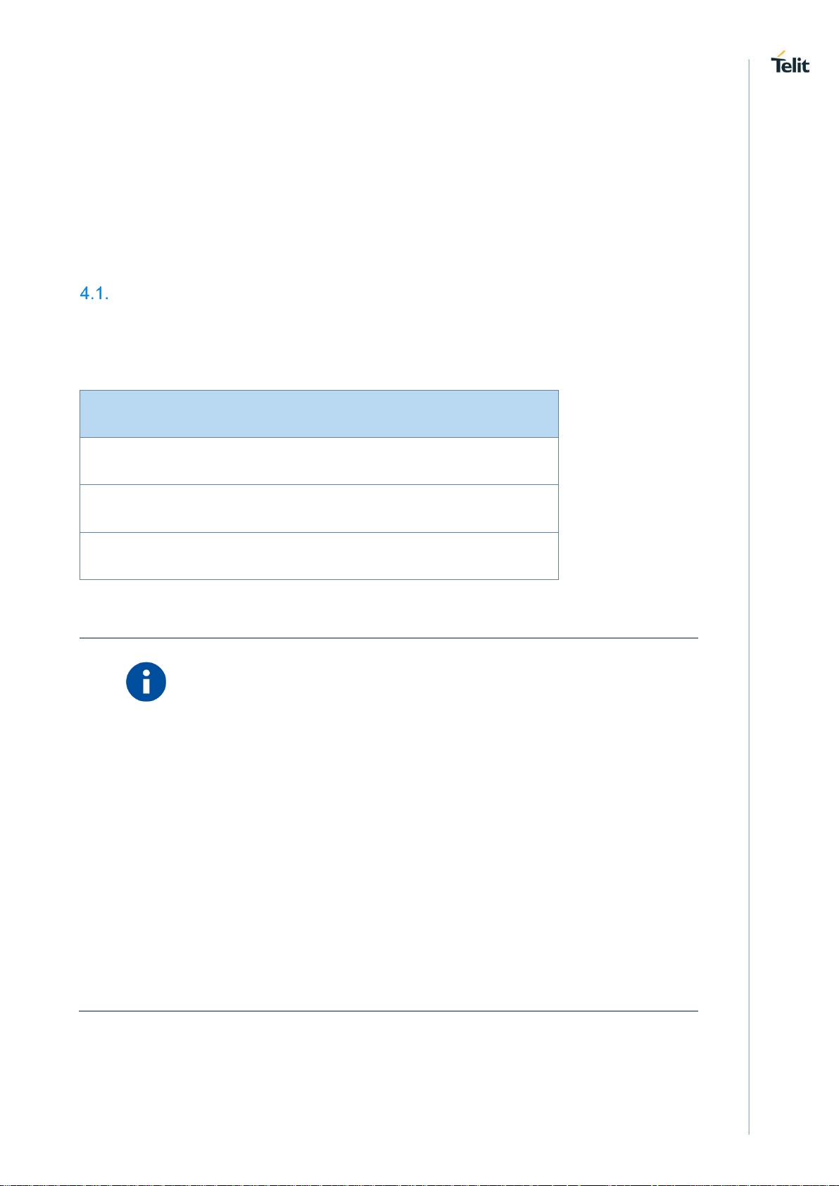
Note
Operating Temperature
Range
–20°C ÷ +55°C
The module is fully
functional(*) in all the
temperature range, and it
fully meets the 3GPP
specifications.
–40°C ÷ +85°C
The module is fully
functional (*) in all the
temperature range.
Storage and non-
operating Temperature
Range
–40°C ÷ +85°C
Mechanical specifications
2.7.1. Dimensions
The overall dimensions of LE866 family are:
Length: 25 mm
Width: 15 mm
Thickness: 2.2 mm
2.7.2. Weight
The nominal weight of the module is 1.80 grams.
Temperature range
(*) Functional: the module is able to make and receive voice calls, data calls, SMS and
make data traffic.
1VV0301355 Rev. 3 Page 15 of 90 2017-09-07
LE866 Hardware Design Guide
Pin
Signal
I/O
Function
Type
Comment
USB HS 2.0 COMMUNICATION PORT
E5
USB_D+
I/O
USB differential Data (+)
-
E6
USB_D-
I/O
USB differential Data (-)
-
Asynchronous Serial Port (USIF0) – Prog. / Data + HW Flow Control
A4
C103/TXD
I
Serial data input (TXD) from DTE
CMOS 1.8V
A5
C104/RXD
O
Serial data output to DTE
CMOS 1.8V
A2
C108/DTR
I
Input for (DTR) from DTE
CMOS 1.8V
A1
C105/RTS
I
Input for Request to send signal (RTS) from
DTE
CMOS 1.8V
B1
C106/CTS
O
Output for Clear to send signal (CTS) to
DTE
CMOS 1.8V
B2
C109/DCD
O
Output for (DCD) to DTE
CMOS 1.8V
A3
C107/DSR
O
Output for (DSR) to DTE
CMOS 1.8V
B3
C125/RING
O
Output for Ring (RI) to DTE
CMOS 1.8V
Asynchronous Auxiliary Serial Port (USIF1)
C1
TX_AUX
O
Auxiliary UART (TX Data to DTE)
CMOS 1.8V
C2
RX_AUX
I
Auxiliary UART (RX Data from DTE)
CMOS 1.8V
SIM card interface
C7
SIMVCC
-
External SIM signal – Power supply for the
SIM
1.8V Only
B7
SIMRST
O
External SIM signal – Reset
CMOS 1.8
A7
SIMCLK
O
External SIM signal – Clock
CMOS 1.8
3. PINS ALLOCATION
Pin-out
1VV0301355 Rev. 3 Page 16 of 90 2017-09-07
LE866 Hardware Design Guide
A6
SIMIO
I/O
External SIM signal – Data I/O
CMOS 1.8
X SIMIN
I
Presence SIM input
CMOS 1.8
See next chapters
DIGITAL IO
C5
GPIO_01
DVI_WA0
SIM_IN
I/O
INT
Main Function: GPIO01 Configurable GPIO
Alternate function 1: Digital Audio Interface
(WA0)
Alternate Function 2: SIM_IN
CMOS 1.8V
C6
GPIO_02
DVI_RX
SIM_IN
I/O
INT
Main Function: GPIO02 Configurable GPIO
Alternate Function 1: Digital Audio Interface
(RX)
Alternate Function 2: SIM_IN
CMOS 1.8V
D6
GPIO_03
DVI_TX
SIM_IN
I/O
INT
General Purpose IO
Alternate Function 1: Digital Audio Interface
(TX)
Alternate Function 2: SIM_IN
CMOS 1.8V
D5
GPIO_04
DVI_CLK
SIM_IN
I/O
INT
Main Function: GPIO04 Configurable GPIO
Alternate Function1: Digital Audio Interface
(CLK)
Alternate Function 2: SIM_IN
CMOS 1.8V
B5
GPIO_05
SIM_IN
I/O
INT
Main Function: GPIO05 Configurable GPIO
Alternate Function 1: SIM_IN
CMOS 1.8V
B4
GPIO_06
ALARM
SIM_IN
I/O
INT
Main Function: GPIO06 Configurable GPIO
Alternate Function 1: ALARM
Alternate Function 2: SIM_IN
CMOS 1.8V
C4
GPIO_07
STAT_LED
SIM_IN
I/O
INT
Main Function: GPIO07 Configurable GPIO
Alternate Function 1: STATLED
Alternate Function 2: SIM_IN
CMOS 1.8V
D8
VDDIO_IN
I
IO bus Supply input
Power
ADC and DAC
F4
ADC_IN1
AI
Analog/Digital converter input
A/D
Accepted values 0
to 1.0V DC
E4
DAC_OUT
AO
Digital/Analog converter output
D/A
RF Section
G2
MAIN_ANT
I/O
LTE Main Antenna (50 ohm)
RF
C0
DIV_ANT
I
LTE RX Diversity Antenna (50 ohm)
RF
1VV0301355 Rev. 3 Page 17 of 90 2017-09-07
LE866 Hardware Design Guide
Miscellaneous Functions
G4
RESET*
I
Reset Input
VBATT
Pull up to VBATT
(10Kohm)
G6
VAUX/PWRMON
O
1.8V stabilized output
Power ON monitor
Power
3GPP Rel12 PSM (Power Saving Mode)
D3
PSM_WAKE
I
3GPP Rel12 PSM Wake Up
Analog
E8
PSM_STATUS
O
3GPP Rel12 PSM Status
CMOS 1.8V
F8
PSM_ENA_OUT
O
3GPP Rel12 PSM Enable for external LDOs
CMOS 1.8V
Power Supply
E2
VBATT
-
Main power supply (Baseband)
Power
E0
VBATT_PA
-
Main power supply (Radio PA)
Power
E1
VBATT_PA
-
Main power supply (Radio PA)
Power
B0
GND
-
Ground
Power
D0
GND
-
Ground
Power
F0
GND
-
Ground
Power
G0
GND
-
Ground
Power
D1
GND
-
Ground
Power
F1
GND
-
Ground
Power
G1
GND
-
Ground
Power
D2
GND
-
Ground
Power
F2
GND
-
Ground
Power
C3
GND
-
Ground
Power
E3
GND
-
Ground
Power
1VV0301355 Rev. 3 Page 18 of 90 2017-09-07

LE866 Hardware Design Guide
F3
GND
-
Ground
Power
G3
GND
-
Ground
Power
F6
GND
-
Ground
Power
A8
GND
-
Ground
Power
G8
GND
-
Ground
Power
A11
GND
-
Ground
Power
G11
GND
-
Ground
Power
RESERVED
A0
RESERVED
-
RESERVED
G5
RESERVED
-
RESERVED
B6
RESERVED
-
RESERVED
D7
RESERVED
-
RESERVED
E7
RESERVED
-
RESERVED
F7
RESERVED
-
RESERVED
G7
RESERVED
-
RESERVED
B8
RESERVED
-
RESERVED
C8
RESERVED
-
RESERVED
A9
RESERVED
-
RESERVED
B9
RESERVED
-
RESERVED
C9
RESERVED
-
RESERVED
D9
RESERVED
-
RESERVED
E9
RESERVED
-
RESERVED
F9
RESERVED
-
RESERVED
1VV0301355 Rev. 3 Page 19 of 90 2017-09-07

LE866 Hardware Design Guide
WARNING
Reserved pins must not be connected.
G9
RESERVED
-
RESERVED
A10
RESERVED
-
RESERVED
B10
RESERVED
-
RESERVED
C10
RESERVED
-
RESERVED
D10
RESERVED
-
RESERVED
E10
RESERVED
-
RESERVED
F10
RESERVED
-
RESERVED
G10
RESERVED
-
RESERVED
B11
RESERVED
-
RESERVED
C11
RESERVED
-
RESERVED
D4
RESERVED
-
RESERVED
F5
RESERVED
-
RESERVED
F11
RESERVED
-
RESERVED
E11
RESERVED
-
RESERVED
D11
RESERVED
-
RESERVED
1VV0301355 Rev. 3 Page 20 of 90 2017-09-07

LE866 Hardware Design Guide
Pad
Signal
Note
E2
VBATT
E0
VBATT_PA E1
VBATT_PA
B0, D0, F0, G0, D1, F1, G1,
D2, F2, C3, E3, F3, G3, F6,
A8, G8, A11, G11
GND
G2
Main Antenna
C0
Diversity Antenna
A4
C103/TXD
If not used should be connected to a Test Point
A5
C104/RXD
If not used should be connected to a Test Point
A1
C105/RTS
If not used should be connected to a Test Point
B1
C106/CTS
If not used should be connected to a Test Point
G6
VAUX / PWRMON
G4
RESET* C1
TXD_AUX
If not used should be connected to a Test Point
C2
RXD_AUX
If not used should be connected to a Test Point
E5
USB D+
If not used should be connected to a Test Point or an USB
connector
E6
USB D-
If not used should be connected to a Test Point or an USB
connector
C7
SIMVCC
B7
SIMRST
If not used, almost all pins should be left disconnected. The only exceptions are the
following pins:
1VV0301355 Rev. 3 Page 21 of 90 2017-09-07

LE866 Hardware Design Guide
A7
SIMCLK
A6
SIMIO
D8
VDDIO_IN
To be always supplied (or using VAUX/PWRMON or with an
external LDO)
RTS pin should be connected to the GND (on the module side) if flow control is not used.
The above pins are also necessary to debug the application when the module is
assembled on it so we recommend connecting them also to dedicated test point.
1VV0301355 Rev. 3 Page 22 of 90 2017-09-07
LE866 Hardware Design Guide
A B C D E F
G
0
RESERVED
GND
DIV
ANT
GND
VBATT_PA
GND
GND
1
C105/RTS
C106/CTS
TX AUX
GND
VBATT_PA
GND
GND
2
C108/DTR
C109/DCD
RX AUX
GND
VBATT
GND
MAIN
ANT
3
C107/DSR
C125/RING
GND
PSM_WAK
E
GND
GND
GND
4
C103/TXD
GPIO_06
GPIO_07
RESERVED
DAC_OUT
ADC_IN1
RESET*
5
C104/RXD
GPIO_05
GPIO_01
GPIO_04
USB_D+
RESERVED
RESERVED
6
SIMIO
RESERVED
GPIO_02
GPIO_03
USB_D-
GND
VAUX/PWR
MON
7
SIMCLK
SIMRST
SIMVCC
RESERVED
RESERVED
RESERVED
RESERVED
8
GND
RESERVED
RESERVED
VDDIO_IN
PSM_STAT
US
PSM_ENA_
OUT
GND
9
RESERVED
RESERVED
RESERVED
RESERVED
RESERVED
RESERVED
RESERVED
10
RESERVED
RESERVED
RESERVED
RESERVED
RESERVED
RESERVED
RESERVED
11
GND
RESERVED
RESERVED
RESERVED
RESERVED
RESERVED
GND
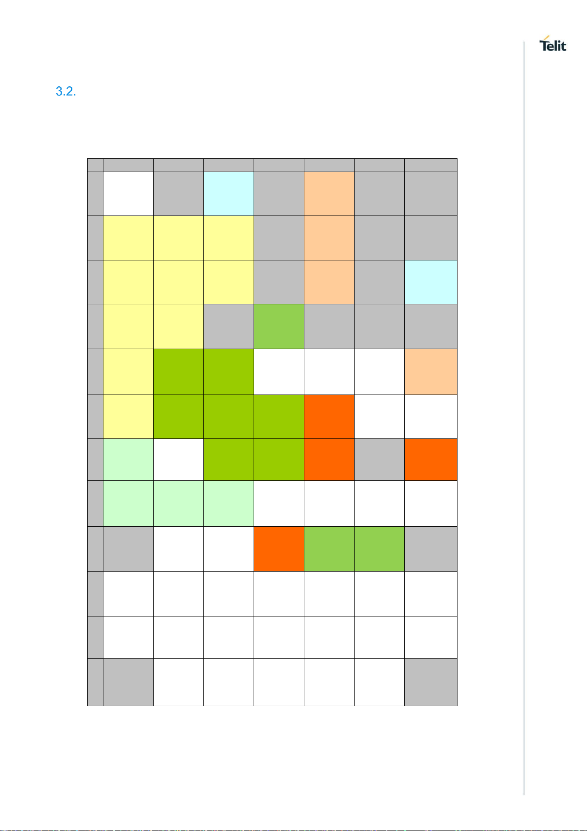
LGA Pads Layout
TOP VIEW
1VV0301355 Rev. 3 Page 23 of 90 2017-09-07
LE866 Hardware Design Guide
Power Supply
Value
Nominal Supply Voltage
3.8V
Normal Operating Voltage Range
3.40 V÷ 4.20 V
Extended Operating Voltage Range
3.10 V÷ 4.50 V
NOTE:
The Operating Voltage Range MUST never be exceeded; care must
be taken when designing the application’s power supply section to
avoid having an excessive voltage drop.
If the voltage drop is exceeding the limits it could cause a Power Off
of the module.
Overshoot voltage (regarding MAX Extended Operating Voltage) and
drop in voltage (regarding MIN Extended Operating Voltage) MUST
never be exceeded;
The “Extended Operating Voltage Range” can be used only with
completely assumption and application of the HW User guide
suggestions.
4. POWER SUPPLY
The power supply circuitry and board layout are a very important part in the full product
design and they strongly reflect on the product overall performances, hence read carefully
the requirements and the guidelines that will follow for a proper design.
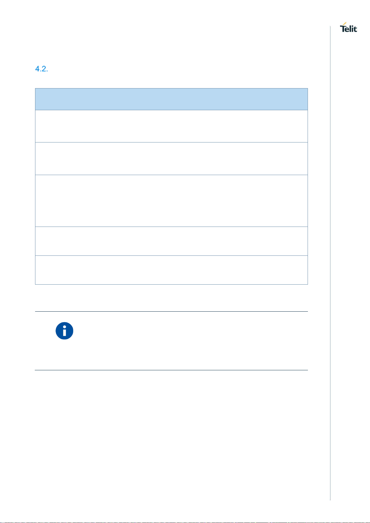
Power Supply Requirements
The external power supply must be connected to VBATT & VBATT_PA signals and must
fulfil the following requirements:
1VV0301355 Rev. 3 Page 24 of 90 2017-09-07
LE866 Hardware Design Guide
Mode
Average (mA)
Mode Description
AT+CFUN=1
23.4
Connected mode
USB Not connected
AT+CFUN=4
21.0
Radio Disabled
USB Not connected
AT+CFUN=5
3.0
Power Saving Enabled
USB not connected
I-DRX (3GPP Rel.8) – paging
2.56s
LTE Data Call (Min Power)
395
LTE data call (channel BW 5MHz,
RB=1, TX=0dBm)
LTE Data Call (Max Power)
580
LTE data call (channel BW 5MHz,
RB=1, TX=22dBm)
NOTE:
The electrical design for the Power supply should be made ensuring
it will be capable of a peak current output of at least 1 A.
Power Consumption
1VV0301355 Rev. 3 Page 25 of 90 2017-09-07

LE866 Hardware Design Guide
General Design Rules
The principal guidelines for the Power Supply Design embrace three different design
steps:
the electrical design
the thermal design
the PCB layout.
4.3.1. Electrical Design Guidelines
The electrical design of the power supply depends strongly from the power source where
this power is drained. We will distinguish them into three categories:
+5V input (typically PC internal regulator output)
+12V input (typically automotive)
Battery
4.3.1.1. +5V Source Power Supply Design Guidelines
The desired output for the power supply is 3.8V, hence there’s not a big difference
between the input source and the desired output and a linear regulator can be used.
A switching power supply will not be suited because of the low drop out
requirements.
When using a linear regulator, a proper heat sink shall be provided in order to
dissipate the power generated.
A Bypass low ESR capacitor of adequate capacity must be provided in order to cut
the current absorption peaks close to the Module, a 100μF capacitor is usually
suited.
Make sure the low ESR capacitor on the power supply output rated at least 10V.
An example of linear regulator with 5V input is:
1VV0301355 Rev. 3 Page 26 of 90 2017-09-07

LE866 Hardware Design Guide
1VV0301355 Rev. 3 Page 27 of 90 2017-09-07
 Loading...