

Telit Communications S p A XE61 Revised manual

ZE51/61-2.4 RF Module User Guide
1VV0300868 Rev.4 – 23/06/2011

This document is related to the following product :
ZE51/61-2.4 RF module User G uide
1VV0300868 Rev.4 – 23/06/2011
Reproduction forbidden without Telit Communications S.p.A. written authorization - All Rights Reserved page 2 of 54

ZE51/61-2.4 RF Module User Guide
1VV0300868 Rev.4 – 23/06/2011
DISCLAIMER
The information contained in this document is the proprietary information of Telit Communications S.p.A.
and its affiliates (“TELIT”). The contents are confidential and any disclosure to persons other than the
officers, employees, agents or subcontractors of the owner or licensee of this document, without the prior
written consent of Telit, is strictly prohibited.
Telit makes every effort to ensure the quality of the information it makes available. Notwithstanding the
foregoing, Telit does not make any warranty as to the information contained herein, and does not accept
any liability for any injury, loss or damage of any kind incurred by use of or reliance upon the information.
Telit disclaims any and all responsibility for the application of the devices characterized in this document,
and notes that the application of the device must comply with the safety standards of the applicable
country, and where applicable, with the relevant wiring rules.
Telit reserves the right to make modifications, additions and deletions to this document due to
typographical errors, inaccurate information, or improvements to programs and/or equipment at any time
and without notice. Such changes will, nevertheless be incorporated into new editions of this document.
Copyright: Transmittal, reproduction, dissemination and/or editing of this document as well as utilization
of its contents and communication thereof to others without express authorization are prohibited.
Offenders will be held liable for payment of damages. All rights are reserved.
© Copyright Telit RF Technologies 2011.
Reproduction forbidden without Telit Communications S.p.A. written authorization - All Rights Reserved page 3 of 54

ZE51/61-2.4 RF module User G uide
1VV0300868 Rev.4 – 23/06/2011
CONTENTS
CHAPTER I. INTRODUCTION ................................................................................................................... 6
I.1. AIM OF THE DOCUMENT .................................................................................................................................................................................... 6
I.2. CONTACT INFORMATION, SUPPORT .................................................................................................................................................................. 6
I.3. REFERENCE DOCUMENTS ................................................................................................................................................................................. 7
I.4. DOCUMENT CHANGE LOG ................................................................................................................................................................................. 7
I.5. GLOSSARY ...................................................................................................................................................................................................... 8
CHAPTER II. REQUIREMENTS ................................................................................................................ 9
II.1. REGULATIONS REQUIREMENTS ........................................................................................................................................................................ 9
II.2. FUNCTIONAL REQUIREMENTS........................................................................................................................................................................ 12
II.3. SOFTWARE .................................................................................................................................................................................................. 12
II.4. TEMPERATURE REQUIREMENTS .................................................................................................................................................................... 13
CHAPTER III. GENERAL CHARACTERISTICS ...................................................................................... 14
III.1. MECHANICAL CHARACTERISTICS ................................................................................................................................................................. 14
III.2. MECHANICAL DIMENSIONS ........................................................................................................................................................................... 15
III.3. DC CHARACTERISTICS ................................................................................................................................................................................ 16
III.4. FUNCTIONAL CHARACTERISTICS .................................................................................................................................................................. 17
III.5. DIGITAL CHARACTERISTICS ......................................................................................................................................................................... 20
III.6. ABSOLUTE MAXIMUM RATINGS .................................................................................................................................................................... 21
III.7. ORDERING INFORMATION ............................................................................................................................................................................ 22
CHAPTER IV. TECHNICAL DESCRIPTION ............................................................................................ 23
IV.1. PIN-OUT OF THE SMD MODULE .................................................................................................................................................................... 23
IV.2. DIP MODULE MECHANICAL DIMENSIONS AND PIN-OUT ................................................................................................................................... 25
IV.3. PIN-OUT CORRESPONDENCE TABLE .............................................................................................................................................................. 26
IV.4. DESCRIPTION OF THE SIGNALS ..................................................................................................................................................................... 27
CHAPTER V. PROCESS INFORMATION ............................................................................................... 28
V.1. DELIVERY ..................................................................................................................................................................................................... 28
V.2. STORAGE ..................................................................................................................................................................................................... 29
V.3. SOLDERING PAD PATTERN ............................................................................................................................................................................. 29
V.4. SOLDER PASTE COMPOSITION (ROHS PROCESS) ........................................................................................................................................... 31
V.5. PLACEMENT .................................................................................................................................................................................................. 31
V.6. SOLDERING PROFILE (ROHS PROCESS) ......................................................................................................................................................... 32
CHAPTER VI. BOARD MOUNTING RECOMMENDATION ..................................................................... 34
VI.1. ELECTRICAL ENVIRONMENT .......................................................................................................................................................................... 34
Reproduction forbidden without Telit Communications S.p.A. written authorization - All Rights Reserved page 4 of 54

ZE51/61-2.4 RF Module User Guide
1VV0300868 Rev.4 – 23/06/2011
VI.2. POWER SUPPLY DECOUPLING ON ZE51/61-2.4 MODULE ............................................................................................................................... 35
VI.3. RF LAYOUT CONSIDERATIONS ...................................................................................................................................................................... 36
VI.4. ANTENNA CONNECTION ON PRINTED CIRCUIT BOARDS ................................................................................................................................. 37
VI.5. ZE51/61-2.4 INTERFACING : ........................................................................................................................................................................ 38
CHAPTER VII. ANTENNA CONSIDERATIONS....................................................................................... 41
VII.1. ANTENNA RECOMMENDATIONS ................................................................................................................................................................... 41
VII.2. ANTENNA MATCHING .................................................................................................................................................................................. 42
VII.3. ANTENNA TYPES ........................................................................................................................................................................................ 43
VII.4. EXTERNAL ANTENNA .................................................................................................................................................................................. 43
VII.5. EMBEDDABLE ANTENNAS ............................................................................................................................................................................ 45
CHAPTER VIII. ANNEXES ....................................................................................................................... 48
VIII.1. DECLARATION OF CONFORMITY ................................................................................................................................................................ 48
VIII.2. CONFORMITY ASSESSMENT ISSUES FCC/IC.............................................................................................................................................. 52
VIII.3. EXAMPLES OF PROPAGATION ATTENUATION ............................................................................................................................................... 53
VIII.4. OUTPUT POWER PROGRAMMING................................................................................................................................................................ 54
Reproduction forbidden without Telit Communications S.p.A. written authorization - All Rights Reserved page 5 of 54
ZE51/61-2.4 RF module User G uide
1VV0300868 Rev.4 – 23/06/2011
CHAPTER I. INTRODUCTION
I.1. Aim of the Document
The aim of this document is to present the features and the application of the ZE51/61-2.4 radio module. After the
introduction, the characteristics of the ZE51/61-2.4 radio module will be described within the following distinct
chapters:
- Requirements
- General Characteristics
- Technical description
- Process information
- Board Mounting Recommendations
- Antenna Considerations
I.2. Contact Information, Support
For general contact, technical support, to report documentation errors and to order manuals, contact Telit Technical
Support Center (TTSC) at:
TS-SRD@telit.com
TS-NORTHAMERICA@telit.com
TS-LATINAMERICA@telit.com
TS-APAC@telit.com
Alternatively, use:
http://www.telit.com/en/products/technical-support-center/contact.php
For detailed information about where you can buy the Telit modules or for recommendations on accessories and
components visit:
http://www.telit.com
To register for product news and announcements or for product questions contact Telit Technical Support Center
(TTSC).
Our aim is to make this guide as helpful as possible. Keep us informed of your comments and suggestions for
improvements. Telit appreciates feedback from the users of our information.
Reproduction forbidden without Telit Communications S.p.A. written authorization - All Rights Reserved page 6 of 54
g
A
I.3. Reference documents
[1] IEEE Std. 802.15.4-2006
ZE51/61-2.4 RF Module User Guide
1VV0300868 Rev.4 – 23/06/2011
Wireless MAC and PHY Specifications for Low Rate - WPANs
[2] ERC Rec 70-03
[3] EN 300 328-1 V1.7.1 (Europe)
[4] EN 300 440-1 V1.6.1 (Europe)
[5] 2002/95/EC
[6] CFR47 Part 15 (US)
[7] ARIB STD-T66 (Japan)
[8] Z-One Pro Protocol Stack User
Guide
[9] 2006/771/EC
[10] 2009/381/EC
[11] SR Manager Tool User Guide
[12] ZigBee PRO Democase Getting
Started
[13] ZigBee PRO Democase User Guide
ERC Recommendation for SRD, October 2010
ETSI Standards for SRD , October 2006
ETSI Standards for SRD , August 2010
Directive of the European Parliament and of the Council, 27 January
2003
FCC Standards for SRD
ARIB Standards for SRD
1vv0300902
Harmonization of the radio spectrum for use by short-range devices
Amending Decision 2006/771/EC on harmonization of the radio
spectrum for use by short-range devices
1vv0300899
1vv0300901
1vv0300900
I.4. Document change log
RReevviissiioonn DDaattee
ISSUE # 0 11/05/10 First Release
ISSUE # 1 28/07/10 Added ZE61-2.4
ISSUE # 2 04/02/11 Updated regulation requirements and schematics in VI.5
ISSUE # 3 14/03/11 Added link for ZE51 USB dongle drivers, info regarding CC debugger.
ISSUE # 4 23/05/11 Added text regarding Conformity Assessment Issues FCC/IC and
Reproduction forbidden without Telit Communications S.p.A. written authorization - All Rights Reserved page 7 of 54
n
geess
CChhaan
Added in Annex paragraph regarding Conformity Assessment Issues
FCC/IC and Declaration of conformity
FCC/IC Certification
Update of Reference documents, DC characteristics, Functional
characteristics, Absolute maximum ratings, DIP module mechanical
dimensions and pin-out labels, Correspondence table and Antenna
matching
dded ZE61-2.4/DIP board radiation pattern

(
)
(
))
g
y
K
V
I.5. Glossary
ARIB
BER
Bits/s
CEPT
CFR
Chips
CW
dBm
DSSS
EIRP
EMC
EPROM
ERC
ETR ETSI Technical Report
ETSI
FCC
IEEE Institute of Electrical and Electronics Engineers
ISM
KB
bps kilobits/s
LBT
LNA
MAC Medium Access Control
MHz
Mchip/s
PCB
PROM
PER
PHY
NRZ
RF
RoHS
RSSI
Rx
SRAM
SRD
SMD
Tx
ia
WPANs
Association of Radio Industries and Businesses
Bit Error Rate
Bits per second
European Conference of Postal and Telecommunications Administrations
Code of Federal Regulations
Chip or chip sequence refers to a spreading-code used to transform the original
data to DSSS
Continuous Wave
Power level in decibel milliwatt
Direct Sequence Spread Spectrum
Effective Isotropic Radiated Power
Electro Ma
Electrical Programmable Read Only Memory
European Radiocommunications Committee
European Telecommunication Standard Institute
Federal Communications Commission
Industrial, Scientific and Medical
1024 bytes (1 byte = 8 bits)
Listen Before Talk
Low Noise Amplifier
Mega Hertz (1 MHz = 1000 kHz)
Mega chips per second (A measure of the speed with which chips are generated
in DSSS)
Printed Circuit Board
Programmable Read Only Memory
Packet Error Rate
Physical Layer
Non return to Zero
Radio Frequency
Restriction of Hazardous Substances
Receive Strength Signal Indicator
Reception
Static Random Access Memory
Short Range Device
Surface Mounted Device
Transmission
Metal Hole on a printed circuit board
Wireless Personal Area Networks
1000 bits/s = 1Kbps = 1Kbaud
10 log (P/1mW
netic Compatibilit
ZE51/61-2.4 RF module User G uide
1VV0300868 Rev.4 – 23/06/2011
Reproduction forbidden without Telit Communications S.p.A. written authorization - All Rights Reserved page 8 of 54

ZE51/61-2.4 RF Module User Guide
1VV0300868 Rev.4 – 23/06/2011
CHAPTER II. REQUIREMENTS
II.1. Regulations requirements
The ZE51/61-2.4 module is a [1],[2],[6],[7] compliant multi channel radio modem in the 2.4GHz band (unlicensed
frequency band).
Europe Regulation:
The “ERC recommendation 70-03” [2] describes the limits band in the 2.4GHz license free band, in terms of bandwidth,
maximum power, duty cycle, channel spacing and type of application. It gives the following limitations:
Class Frequency
band
Annex 1h
(Non-Specific
Short range
Devices)
Annex 3a
(Wideband Data
Transmission
systems)
(*) Compliant to the EU Commission Decision [9], [10]. Techniques to access spectrum and mitigate interference
that provide at least equivalent performance to the techniques described in harmonized standards adopted under
Directive 1999/5/EC must be used.
2400 – 2483.5
MHz
2400 – 2483.5
MHz
Maximum radiated power Channel
spacing
No channel
10 mW e.i.r.p.
100 mW e.i.r.p. and 100
mW/100 kHz e.i.r.p. density
applies when frequency
hopping modulation is used,
10 mW/MHz e.i.r.p. density
applies when other types of
modulation are used.(*)(**)
spacing
specified
No channel
spacing
specified.
Duty cycle Notes
No
restriction
For wide band
No
restriction
modulations other than
FHSS, the maximum
e.i.r.p. density is limited
to 10 mW/MHz
(**) For IEEE802.15.4 DSSS modulation used by ZigBee, the modulated signal is spread over 2MHz. So, the
maximum radiated power is 20mW. The output power must therefore be reduced to approximately +13 dBm in
order to get CE approval. The final output power level will depend on the antenna used.
Reproduction forbidden without Telit Communications S.p.A. written authorization - All Rights Reserved page 9 of 54

y
ZE51/61-2.4 RF module User G uide
1VV0300868 Rev.4 – 23/06/2011
Restrictions for non specific SR devices Annex 1h 2400-2483.5MHz:
Country Restriction Reason/Remark
This subsection does not apply for the
Norway Implemented
Russian
Federation
Bluetooth
geographical area within a radius of 20 km
from the centre of N
-Ålesund
Ukraine Limited implementation e.i.r.p. ≤100 mW
Restrictions for Wideband Data Transmission systems Annex 3a 2400-2483.5MHz:
Country Restriction Reason/Remark
Military Radiolocation use. Reforming of
Outdoor use limited to 10
France
mW e.i.r.p. within the
band 2454-2483.5 MHz
Italy
Ukraine Limited Implemented
Norway Implemented
Russian
Federation
the 2.4 GHz band has been ongoing in
recent years to allow current relaxed
regulation. Full implementation planned
2012
For private use, a general authorisation is
required if WAS/RLAN’s are used outside
own premises. For public use, a general
authorization is required
e.i.r.p. ≤100 mW with built-in antenna with
amplification factor up to 6 dBi
This subsection does not apply for the
geographical area within a radius of 20 km
from the centre of Ny-Ålesund
1. SRD with FHSS modulation
1.1. Maximum 2.5 mW e.i.r.p.
1.2. Maximum 100 mW e.i.r.p. Permitted for
use SRD for outdoor applications without
restriction on installation height only for
purposes of gathering telemetry information for
automated monitoring and resources
accounting systems.
Permitted to use SRD for other purposes for
outdoor applications only when the installation
height is not exceeding 10 m above the ground
surface.
1.3.Maximum 100 mW e.i.r.p. Indoor
applications
2. SRD with DSSS and other than FHSS
wideband modulation
2.1. Maximum mean e.i.r.p. density is 2
mW/MHz. Maximum 100 mW e.i.r.p.
2.2. Maximum mean e.i.r.p. density is 20
mW/MHz. Maximum 100 mW e.i.r.p. Permitted
to use SRD for outdoor applications
only for purposes of gathering telemetry
information for automated monitoring and
Reproduction forbidden without Telit Communications S.p.A. written authorization - All Rights Reserved page 10 of 54
ZE51/61-2.4 RF Module User Guide
1VV0300868 Rev.4 – 23/06/2011
resources accounting systems or
security systems.
2.3. Maximum mean e.i.r.p. density is 10
mW/MHz. Maximum
100 mW e.i.r.p. Indoor applications
For the complete document please refer to [2
The 2.4 Ghz band is a harmonized band in most of Europe. So the product must be declared in compliance with
the harmonized ETSI standards EN 300 440 (Class 1h) or EN 300 228 (Class 3a).
Finally, the module complies with the new European Directive 2002/95/EC concerning the Restrictive Usage of
Hazardous Substances (RoHS).
] and EU Commission Decision [9], [10].
USA Regulation:
In the United States the FCC is responsible for the regulation of all RF devices. Our module intended for
unlicensed operation is regulated by CFR 47, Part 15 [6].
The 2.4 GHz band used for unlicensed radio equipment is regulated by section 15.247.
Japan regulation
In Japan the unlicensed use of short range devices in the 2.4 GHz ISM band is regulated by the ARIB standard
STD-T66 [7].
Reproduction forbidden without Telit Communications S.p.A. written authorization - All Rights Reserved page 11 of 54
ZE51/61-2.4 RF module User G uide
1VV0300868 Rev.4 – 23/06/2011
II.2. Functional Requirements
The ZE51/61-2.4 module is a complete solution from serial interface to RF interface. The ZE51/61-2.4 module has
a digital part and a RF part.
The digital part has the following functionalities:
- Communication interface
- I/O management
- Micro controller with embedded software
The RF part has the following functionalities:
- 2.4 GHz IEEE 802.15.4 compliant RF transceiver
- Half Duplex bi-directional link
- RF front-end component with low noise Rx amplification and Tx power amplification (ZE61-2.4 module
only)
II.3. Software
The ZE51/61-2.4 module is provided pre-flashed with Telit in-house ZigBee® PRO stack. Please refer to ZigBee
PRO Protocol Stack User Guide [8] for detail information.
In case the customer needs to develop his own software, different tools are available:
8051 compiler from IAR : http://www.iar.se/website1/1.0.1.0/244/1/
CC debugger: http://focus.ti.com/docs/toolsw/folders/print/cc-debugger.html
The technical support for these tools will be done by the providing company.
All necessary drivers for ZE51-2.4 Usb dongle can be found under the following link:
http://www.ftdichip.com/Drivers/VCP.htm
A complete correspondence table of the connections between the CC2530 and the pin out of the module, as well
as the connections to the included STM M24C64 EEPROM can be found in chapter IV.3.
In case, the customer wants to test the RF performances of the module, Telit can provide its own
proprietary test software that is available in the download zone together with description of all the
functionalities.
Reproduction forbidden without Telit Communications S.p.A. written authorization - All Rights Reserved page 12 of 54
II.4. Temperature Requirements
Minimum Typical Maximum Unit
Operating
Temperature - 40 25 + 85 °C
Relative humidity @ 25°C 20 75 %
Storage
Temperature - 40 25 + 85 °C
ZE51/61-2.4 RF Module User Guide
1VV0300868 Rev.4 – 23/06/2011
Reproduction forbidden without Telit Communications S.p.A. written authorization - All Rights Reserved page 13 of 54

ZE51/61-2.4 RF module User G uide
1VV0300868 Rev.4 – 23/06/2011
CHAPTER III. GENERAL CHARACTERISTICS
III.1. Mechanical Characteristics
Size : Rectangular 26 x 15 mm
Height : 3 mm
Weight : 1,7 g
PCB thickness: 0.8 mm
Cover :
Components : All SMD components, on one side of the PCB.
Connectors : The terminals allowing conveying I/O signals are half-moons located around.
Mounting :
Number of pins : 30
Dimensions : 21 x 14 x 2.2mm
Thickness : 200µm
SMD
Half moons on the 4 external sides
Reproduction forbidden without Telit Communications S.p.A. written authorization - All Rights Reserved page 14 of 54
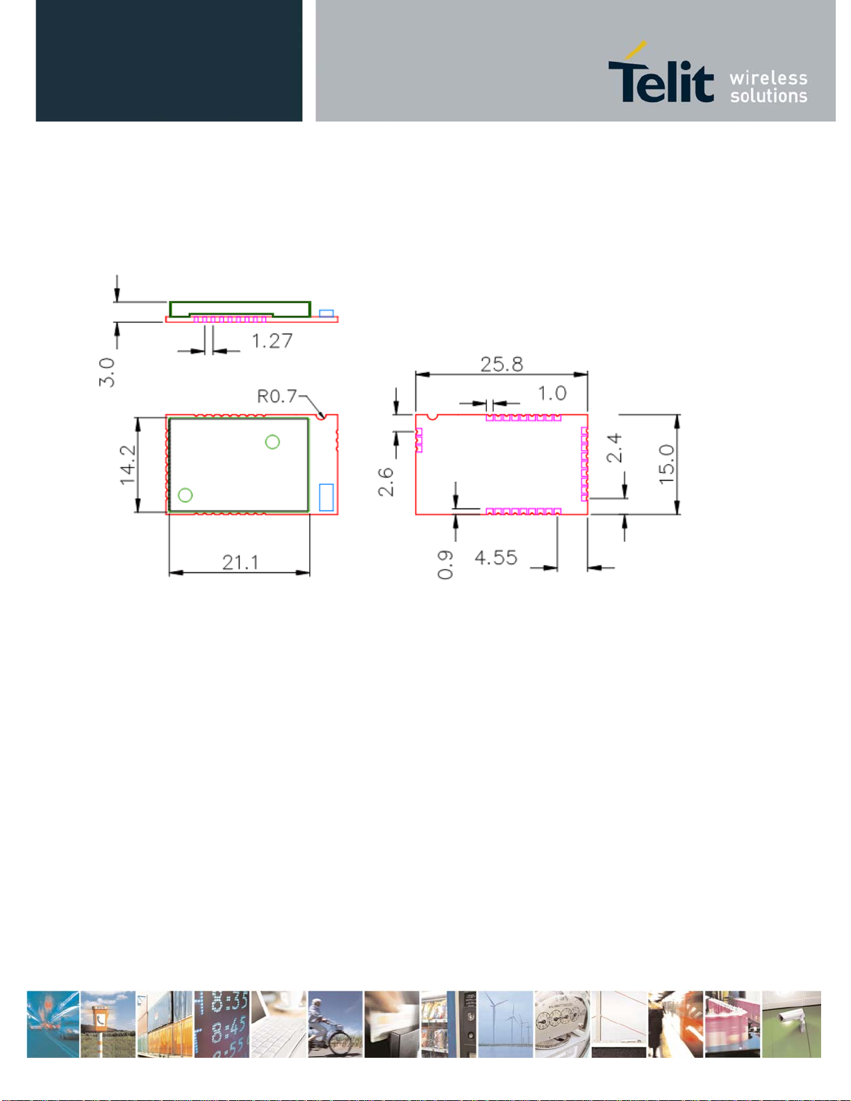
III.2. Mechanical dimensions
ZE51/61-2.4 RF Module User Guide
1VV0300868 Rev.4 – 23/06/2011
Reproduction forbidden without Telit Communications S.p.A. written authorization - All Rights Reserved page 15 of 54
ZE51/61-2.4 RF module User G uide
1VV0300868 Rev.4 – 23/06/2011
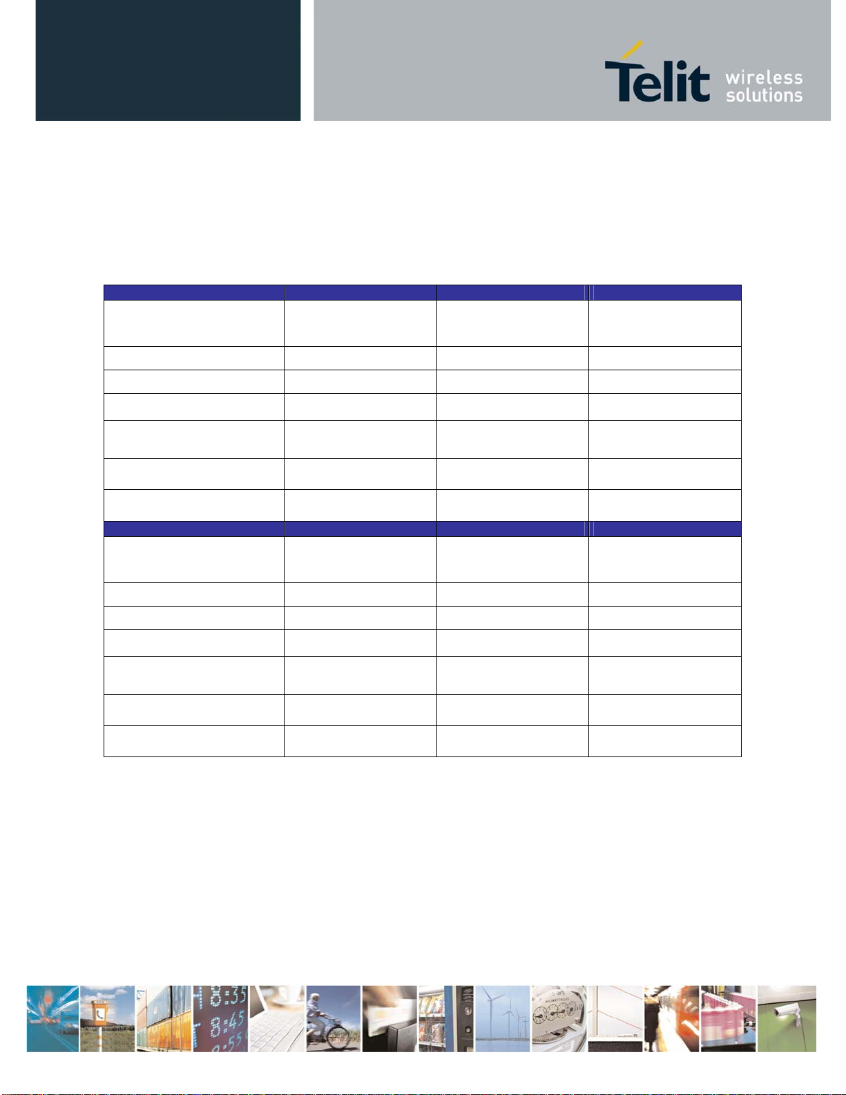
III.3. DC Characteristics
Measured on ZE51/61-2.4/DIP interface with T = 25°C, Vdd = 3V, 50 ohm impedance if nothing else
noted.
Max limits apply over the entire operating range, T=-40°C to +85°C, Vdd=2V to 3.6V and all channels.
Characteristics ZE51 Min. Typ. Max.
Power Supply
(V
DD):
+2.0V +3.6V
Transmission :
Reception :
Stand-by (32.768 khz On) :
Sleep (wake up on
interruption) :
35mA 39mA*
26mA 29mA
2µA 2.7µA
1µA
I/O low level : GND - 0.9 V
I/O high level : V
- 0.7V - VDD
DD
Characteristics ZE61 Min. Typ. Max.
Power Supply
(V
DD):
Transmission :
Reception :
Stand-by (32.768 khz On) :
Sleep (wake up on
interruption) :
+2.0V +3.6V
160mA 195mA*
31mA 33mA
2,2µA 2.9µA
1,5µA
I/O low level : GND - 0.9 V
I/O high level : V
- 0.7V - VDD
DD
* : Maximum Tx consumption is reached for T= -40°C , Vdd=3.6 Volts and default power register setting. In this
condition, the ZE61 RF output power achieves until 21dBm.
Reproduction forbidden without Telit Communications S.p.A. written authorization - All Rights Reserved page 16 of 54

ZE51/61-2.4 RF Module User Guide
1VV0300868 Rev.4 – 23/06/2011
III.4. Functional characteristics
Measured on ZE51/61-2.4/DIP interface with T = 25°C, Vdd = 3V, 50 ohm impedance if nothing else noted.
Global
Frequency band 2400 - 2483.5 MHz
Channel spacing 5 MHz
Channel number
16 : Channel 11 (2405MHz) Channel 26 (2480MHz)
Technology DSSS
Modulation O-QPSK with half sine pulse shaping
Radio bit rate 250 kbps
Transmit chip rate 2 Mchip/s
Transmission ZE 5 1 Min. Typ. Max.
Output Power +4dBm ± 1 dB on the whole band
(selectable by software )
Harmonics
nd
2
3
harmonic
rd
harmonic
Spurious emission
30 - 1000 MHz
1 - 12.75 GHz
1.8 - 1.9 GHz
5.15 - 5.3 GHz
-45 dBm
-59 dBm
-36 dBm
-30 dBm
-47 dBm
-47 dBm
(Complies with [3], [4],
[6],[7])
Error Vector Magnitude
(EVM)
5% 15%
Transmission ZE 6 1 Min. Typ. Max.
Output Power* +19dBm ± 1 dB on the whole band
(selectable by software )
Harmonics
nd
2
3
harmonic
rd
harmonic
-42 dBm
-44 dBm
Spurious emission
30 - 1000 MHz
1 - 12.75 GHz
1.8 - 1.9 GHz
5.15 - 5.3 GHz
Reproduction forbidden without Telit Communications S.p.A. written authorization - All Rights Reserved page 17 of 54
-36 dBm
-30 dBm
-47 dBm
-47 dBm
 Loading...