

TELITAL MOBITEL TELMOSS User Manual
U
SER’S
G
UIDE
CONTENTS
INTRODUCTION...................................................................................................... 1
PACKAGE CONTENTS .............................................................................................. 2
TECHNICAL FEATURES ............................................................................................ 3
CENTRAL UNIT DESCRIPTION ................................................................................. 5
INSTALLATION ....................................................................................................... 8
CAUTION ............................................................................................................ 8
Mounting the central unit ..................................................................................... 8
Hardware installation steps................................................................................... 9
Sensor port pin out .............................................................................................11
CLIENT APPLICATIONS...........................................................................................12
Telmoss mobile...................................................................................................13
Running the application ...................................................................................13
Connection profiles ..........................................................................................14
Making the call ................................................................................................14
Live images.....................................................................................................17
Archive images................................................................................................19
Parameters .....................................................................................................22
Hanging up .....................................................................................................26
Telmoss PC ........................................................................................................27
Installing Telmoss PC application......................................................................27
Running the application ...................................................................................29
Profiles ...........................................................................................................30
On-line menu ..................................................................................................33
Solving problems....................................................................................................38
No power indication.........................................................................................38
GSM signal LEDs flash......................................................................................38
Connection fails ...............................................................................................38
GM862-GPRS Conformity Assessment......................................................................39
Telmoss user’s guide 1/42
2004. Telital mobitel d.o.o. All right reserved.
INTRODUCTION
Thank you for choosing this product. Please read carefully this manual to make the
best use of the entire system.
The system itself contains central hardware unit, Telmoss, which is actually GSM video
transmitter. It works, completely automatically, on 2 frequency bands: 900 and 1800
MHz ensuring an excellent radio coverage.
In first sections hardware installation will be presented. Please, pay attention specially
to the articles related to the SIM card installation.
Last sections describe client application and system’s parameter setup.
NOTE
In accordance with on-going improvements, the specifications, design
and other descriptions in this manual are subjects to modifications
without prior notice.
Telmoss user’s guide 2/42
2004. Telital mobitel d.o.o. All right reserved.
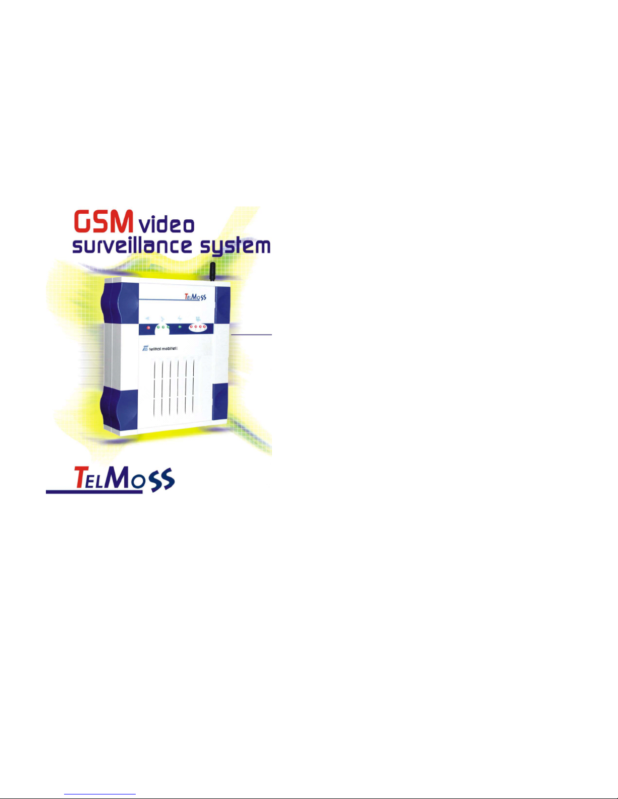
PACKAGE CONTENTS
TelMoss box contains following items:
• TelMoss central unit (1)
• Power supply adapter 230V-AC / 12V-DC (2)
• Dual Band GSM antenna (3)
• CD ROM with client applications and user manual
Figure 1
1
2
3

Telmoss user’s guide 3/42
2004. Telital mobitel d.o.o. All right reserved.
TECHNICAL FEATURES
Basics
• used as a stand alone device or an upgrade to installed video surveillance system
• all parameter setup performed through client applications
• built in GSM modem
• connection for standard, external modem (RS232)
• CSD data transfer
OS supported
• Symbian Series 60 OS
• Windows XP
Connectivity
• 4x analog video in,BNC
• D-SUB 9-pin male RS-232 connector for external modem
• D-SUB 9-pin female connector for alarm inputs
• power supply
• SMA connector for external GSM antenna
• SIM card socket
Video
• PAL, SECAM i NTSC video formats
• scan resolutions: 160x120, 320x240 i 640x480 pixels
• 5 predefined compression levels
• color and C/B mode
• digital zoom up to 4x
• date/time stamp
• image storing directly into client’s device memory
Telmoss user’s guide 4/42
2004. Telital mobitel d.o.o. All right reserved.
Dimensions
• H: 52 mm
• L: 196 mm
• W: 174 mm
Mounting
• wall
• table
Power supply
• external 12 V- DC, min. 500mA
Telmoss user’s guide 5/42
2004. Telital mobitel d.o.o. All right reserved.
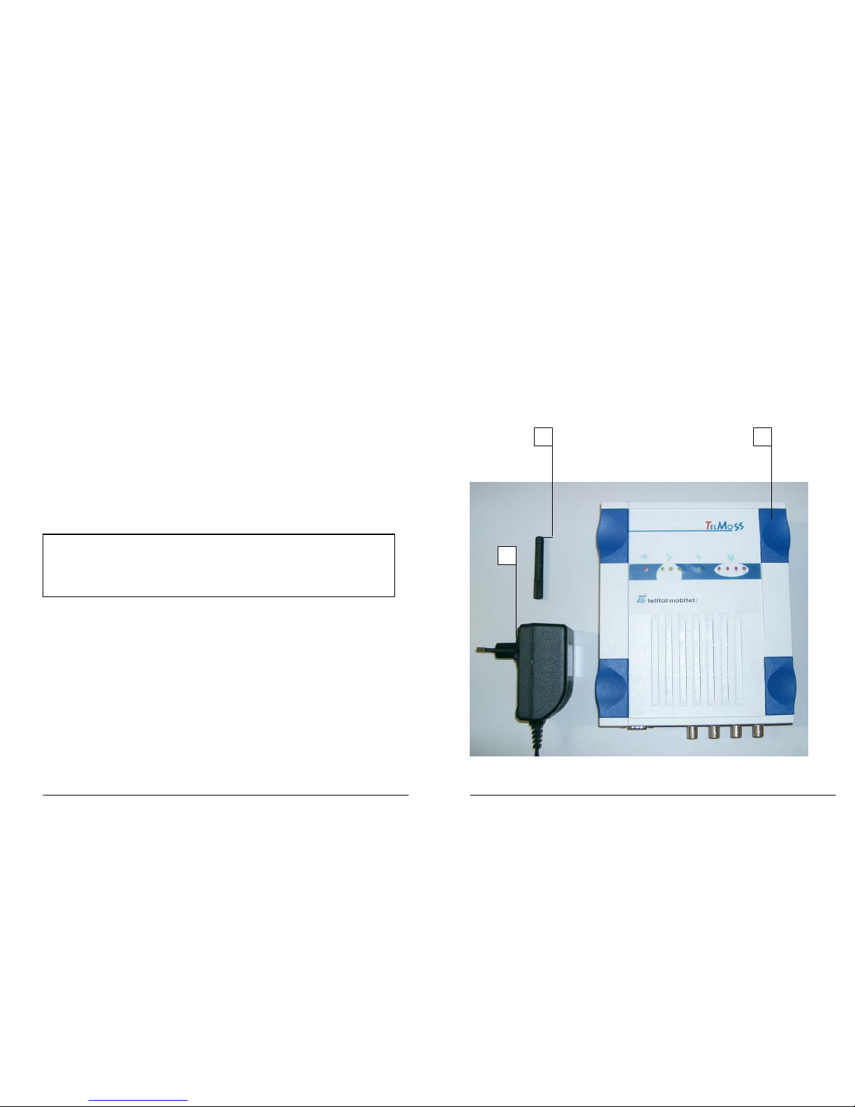
CENTRAL UNIT DESCRIPTION
Here is the brief description of main Telmoss parts:
1. SMA connector for GSM antenna connection
2. SIM card (small format)
Figure 2 Upper panel
Figure 3 Down panel
3. DB9 female connector for alarm inputs (see Installation)
4. DB9 male RS 232 connector for external modem connection
1
2
6
3 4
5
-
Telmoss user’s guide 6/42
2004. Telital mobitel d.o.o. All right reserved.
5. 4 pin power supply connector (12 V - DC), 2 pins are used (+,-)
6. 4 BNC video inputs
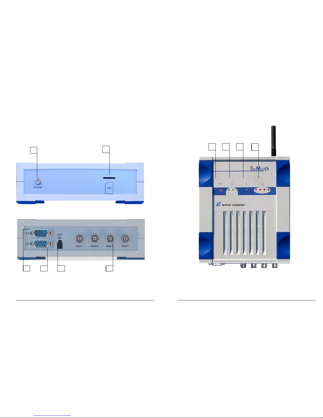
Figure 4 Front panel
7 8 9
10

Telmoss user’s guide 7/42
2004. Telital mobitel d.o.o. All right reserved.
7. power supply presence indicator (lights if power supply is ok, but only after
boot sequence which takes ca.55 seconds after switching on)
8. GSM signal strength indicator (3 levels)
9. traffic/communication indicator (blinks if there is rx/tx traffic)
10. video signal indicator (light red if video signals are presented)
Telmoss user’s guide 8/42
2004. Telital mobitel d.o.o. All right reserved.
INSTALLATION
CAUTION
Telmoss device should not be used in an explosive environment (petrol
stations, refineries, fuel depots, chemical plants etc.) unless it is housed in
an approved explosion protection enclosure.
Telmoss device is to be positioned at least 20 cm from the human body
during it's operation.
Mounting the central unit
Telmoss device must be installed at the proper position where GSM signal coverage is
good enough. The unit can be mounted either on the wall or on the table. From the
security reasons, like other video surveillance systems, the main unit should be hidden
somewhere inside observed area in order not to be easily reachable nor visible.
Once the final position for central unit is defined, all cables (power adapter cable,
coaxial from cameras and wires from sensors) must reach appropriate connectors at
the unit (see Figure 3).
NOTE
Camera and sensor mounting procedures are out of the scope of this manual.

Telmoss user’s guide 9/42
2004. Telital mobitel d.o.o. All right reserved.
Hardware installation steps
1. MOUNTING THE ANTENNA
Apply GSM antenna (Figure 1, pos 3) to the SMA connector (Figure 2, pos 1). Make
sure that antenna is fasten enough (turning it few times to right till reach the end of
the thread) in order to ensure good signal reception.
2. INSERTING THE SIM CARD
Insert the SIM card into the slot as shown on Figure 2, position 2.
NOTE:
• PIN request must be disabled on applied SIM card. For this purpose use standard
GSM mobile phone and disable this function. For details refer to mobile phone
user’s guide.
• applied SIM card must have so called Data/fax subscription number activated. This
number is dedicated for incoming data calls. For more information refer to your
network operator.
3. PLUG-IN THE CABLES
Plug-in coaxial cables (Figure 3, pos 6) from the cameras previously installed and
connect the wires from sensors (see more details in chapter Sensor port )
4. PLUG-IN POWER SUPLLY
Plug-in the power supply cable to the connector shown on Figure 3, position 5 and
power supply adapter to the mains socket (220V).
5. WATCH THE LED INDICATORS
If the power supply is connected properly, the boot sequences starts and after ca. 22
seconds Red Power Supply LED indicator (Figure 4, pos 7) will start to flash. This will
last ca. 30-35 seconds. In the mean time all 3 green GSM signal indicators (Figure 4
pos 8) will blink on/off few times, indicating the presence of GSM module.
Approximately 55 seconds after switching on, Red Power Supply LED indicator stops
flashing and must remain switched on permanently.
Those Camera LEDs are turned on, whose connectors are supplied with proper video
signal.
About ten seconds afterwards, the unit should be properly connected to the network
indicating the signal strength on 3 green LEDs. If those LEDs start to flash please wait
for few seconds (10-20). If this continues, it indicates the permanent problem with the
connection.
So, the device is properly installed if:
• RED Power Supply LED indicator is switched on
Telmoss user’s guide 10/42
2004. Telital mobitel d.o.o. All right reserved.
• at least 1 GREEN GSM signal indicator is switched on
• at least 1 RED Camera indicator is switched on
Now, if all listed steps are performed successfully, parameter set-up has to be done
using one of the client applications.
NOTE
If SIM card has not been inserted before switching on Telmoss device, the
system software will consider ONLY external devices connected to RS232
connector (Figure 3, pos 4) as the communication devices i.e. external
modem, direct cable connection to PC etc. All three GSM signal LEDs will
blink continuously. Communication will be possible only through this port
and no notification SMS will be sent.
Telmoss user’s guide 11/42
2004. Telital mobitel d.o.o. All right reserved.
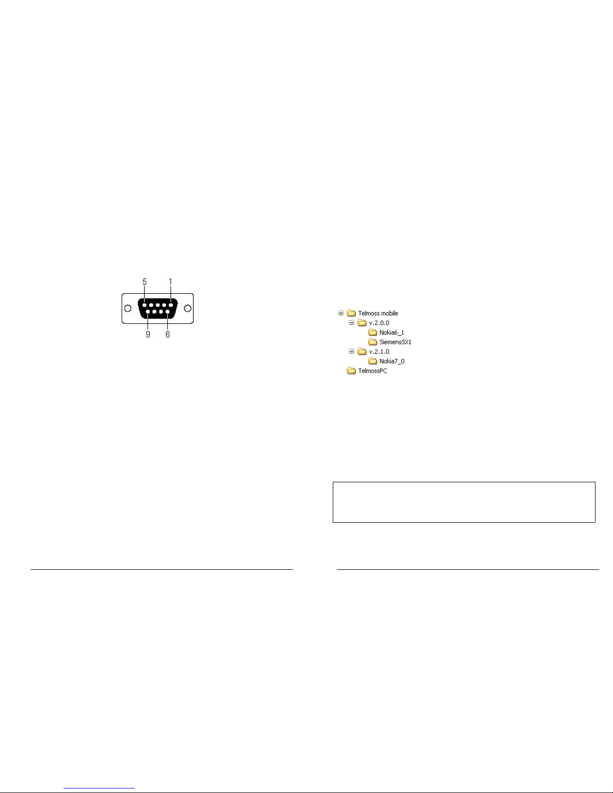
Sensor port pin out
Four dry, relay sensor inputs can be connected to Telmoss sensor port. Connector pin-
-out is shown on the picture below.
D-sub 9 pins female connector (see Figure 3, poz.4)
PIN 4 & 9 – relay input 1
PIN 3 & 8 – relay input 2
PIN 2 & 7 – relay input 3
PIN 1 & 6 – relay input 4
Telmoss user’s guide 12/42
2004. Telital mobitel d.o.o. All right reserved.
CLIENT APPLICATIONS
The main purpose of client applications is the control over the system either in the
sense of remote viewing or parameter set-up. There are two client applications:
•
Telmoss mobile
dedicated for the use on mobile phones running
SymbianOS Series60.
•
Telmoss PC
dedicated for the use on personal computers running on
Windows XP OS.
Telmoss CD directory tree:
Telmoss mobile installation
In each subfolder of
Telmoss mobile
directory there is a file
Telmoss mobileENG.sis.
Those are installation files (English versions) for Symbian OS which are dedicated for
following mobile phones:
v.2.0.0/Nokia6_1 for Nokia7650, 3650,3660, NGage
v.2.0.0/SiemensSx1 for Siemens SX1
v.2.1.0/Nokia7_0 for Nokia 6600, 7610 and newer
NOTE
For the details on application install procedure please refer to original
mobile phone's manual.
 Loading...