

Page 1

WE310F5-X AT Command
Reference Guide
80664ST11034A Rev. 4 – 2020-08-25
Page 2

WE310F5-X AT Command Reference Guide
80664ST11034A Rev. 4 Page 2 of 174 2020-08-25
SPECIFICATIONS ARE SUBJECT TO CHANGE WITHOUT NOTICE
NOTICES LIST
While reasonable efforts have been made to assure the accuracy of this document, Telit assumes no liability
resulting from any inaccuracies or omissions in this document, or from use of the information obtained
herein. The information in this document has been carefully checked and is believed to be reliable. However,
no responsibility is assumed for inaccuracies or omissions. Telit reserves the right to make changes to any
products described herein and reserves the right to revise this document and to make changes from time to
time in content hereof with no obligation to notify any person of revisions or changes. Telit does not assume
any liability arising out of the application or use of any product, software, or circuit described herein; neither
does it convey license under its patent rights or the rights of others.
It is possible that this publication may contain references to, or information about Telit products (machines
and programs), programming, or services that are not announced in your country. Such references or
information must not be construed to mean that Telit intends to announce such Telit products, programming,
or services in your country.
COPYRIGHTS
This instruction manual and the Telit products described in this instruction manual may be, include or
describe copyrighted Telit material, such as computer programs stored in semiconductor memories or other
media. Laws in the Italy and other countries preserve for Telit and its licensors certain exclusive rights for
copyrighted material, including the exclusive right to copy, reproduce in any form, distribute and make
derivative works of the copyrighted material. Accordingly, any copyrighted material of Telit and its licensors
contained herein or in the Telit products described in this instruction manual may not be copied, reproduced,
distributed, merged or modified in any manner without the express written permission of Telit. Furthermore,
the purchase of Telit products shall not be deemed to grant either directly or by implication, estoppel, or
otherwise, any license under the copyrights, patents or patent applications of Telit, as arises by operation
of law in the sale of a product.
COMPUTER SOFTWARE COPYRIGHTS
The Telit and 3rd Party supplied Software (SW) products described in this instruction manual may include
copyrighted Telit and other 3rd Party supplied computer programs stored in semiconductor memories or
other media. Laws in the Italy and other countries preserve for Telit and other 3rd Party supplied SW certain
exclusive rights for copyrighted computer programs, including the exclusive right to copy or reproduce in
any form the copyrighted computer program. Accordingly, any copyrighted Telit or other 3rd Party supplied
SW computer programs contained in the Telit products described in this instruction manual may not be
copied (reverse engineered) or reproduced in any manner without the express written permission of Telit or
the 3rd Party SW supplier. Furthermore, the purchase of Telit products shall not be deemed to grant either
directly or by implication, estoppel, or otherwise, any license under the copyrights, patents or patent
applications of Telit or other 3rd Party supplied SW, except for the normal non-exclusive, royalty free license
to use that arises by operation of law in the sale of a product.
Page 3

WE310F5-X AT Command Reference Guide
80664ST11034A Rev. 4 Page 3 of 174 2020-08-25
USAGE AND DISCLOSURE RESTRICTIONS
I. License Agreements
The software described in this document is the property of Telit and its licensors. It is furnished by express
license agreement only and may be used only in accordance with the terms of such an agreement.
II. Copyrighted Materials
Software and documentation are copyrighted materials. Making unauthorized copies is prohibited by law.
No part of the software or documentation may be reproduced, transmitted, transcribed, stored in a retrieval
system, or translated into any language or computer language, in any form or by any means, without prior
written permission of Telit
III. High Risk Materials
Components, units, or third-party products used in the product described herein are NOT fault-tolerant and
are NOT designed, manufactured, or intended for use as on-line control equipment in the following
hazardous environments requiring fail-safe controls: the operation of Nuclear Facilities, Aircraft Navigation
or Aircraft Communication Systems, Air Traffic Control, Life Support, or Weapons Systems (High Risk
Activities"). Telit and its supplier(s) specifically disclaim any expressed or implied warranty of fitness for such
High Risk Activities.
IV. Trademarks
TELIT and the Stylized T Logo are registered in Trademark Office. All other product or service names are
the property of their respective owners.
V. Third Party Rights
The software may include Third Party Right software. In this case you agree to comply with all terms and
conditions imposed on you in respect of such separate software. In addition to Third Party Terms, the
disclaimer of warranty and limitation of liability provisions in this License shall apply to the Third-Party Right
software.
TELIT HEREBY DISCLAIMS ANY AND ALL WARRANTIES EXPRESS OR IMPLIED FROM ANY THIRD
PARTIES REGARDING ANY SEPARATE FILES, ANY THIRD PARTY MATERIALS INCLUDED IN THE
SOFTWARE, ANY THIRD PARTY MATERIALS FROM WHICH THE SOFTWARE IS DERIVED
(COLLECTIVELY “OTHER CODE”), AND THE USE OF ANY OR ALL THE OTHER CODE IN
CONNECTION WITH THE SOFTWARE, INCLUDING (WITHOUT LIMITATION) ANY WARRANTIES OF
SATISFACTORY QUALITY OR FITNESS FOR A PARTICULAR PURPOSE.
NO THIRD PARTY LICENSORS OF OTHER CODE SHALL HAVE ANY LIABILITY FOR ANY DIRECT,
INDIRECT, INCIDENTAL, SPECIAL, EXEMPLARY, OR CONSEQUENTIAL DAMAGES (INCLUDING
WITHOUT LIMITATION LOST PROFITS), HOWEVER CAUSED AND WHETHER MADE UNDER
CONTRACT, TORT OR OTHER LEGAL THEORY, ARISING IN ANY WAY OUT OF THE USE OR
DISTRIBUTION OF THE OTHER CODE OR THE EXERCISE OF ANY RIGHTS GRANTED UNDER
EITHER OR BOTH THIS LICENSE AND THE LEGAL TERMS APPLICABLE TO ANY SEPARATE FILES,
EVEN IF ADVISED OF THE POSSIBILITY OF SUCH DAMAGES.
Page 4

WE310F5-X AT Command Reference Guide
80664ST11034A Rev. 4 Page 4 of 174 2020-08-25
APPLICABILITY TABLE
PRODUCTS
SW Versions
Modules
WE310F5-X SERIES
39.00.000
Page 5

WE310F5-X AT Command Reference Guide
80664ST11034A Rev. 4 Page 5 of 174 2020-08-25
CONTENTS
NOTICES LIST ............................................................................................................... 2
COPYRIGHTS ................................................................................................................ 2
COMPUTER SOFTWARE COPYRIGHTS ..................................................................... 2
USAGE AND DISCLOSURE RESTRICTIONS.............................................................. 3
APPLICABILITY TABLE................................................................................................ 4
CONTENTS 5
FIGURES LIST ............................................................................................................. 11
TABLES LIST ............................................................................................................... 12
1. INTRODUCTION ...................................................................................... 14
Scope ....................................................................................................... 14
Audience .................................................................................................. 14
Contact Information, Support ................................................................... 14
Text Conventions ..................................................................................... 15
Related Documents .................................................................................. 15
2. OVERVIEW .............................................................................................. 16
AT Commands ......................................................................................... 16
Command definition ................................................................................. 16
AT Command Syntax ............................................................................... 17
Command Lines ....................................................................................... 17
Information Response and Result Codes ................................................ 18
3. ARCHITECTURE ..................................................................................... 20
System Overview ..................................................................................... 20
Working Principle ..................................................................................... 21
System Initialization ................................................................................. 21
3.3.1. Auto Connection ....................................................................................... 22
4. HOST INTERACTION .............................................................................. 23
Interface ................................................................................................... 23
4.1.1. UART ........................................................................................................ 23
4.1.1.1. Baud Rate - B ........................................................................................... 23
4.1.1.2. Hardware Flow Control - &Kn .................................................................. 24
5. GENERAL OPERATIONS ....................................................................... 26
System Settings ....................................................................................... 26
5.1.1. Echo Mode - En ....................................................................................... 26
5.1.2. Verbose Mode - Vn .................................................................................. 26
Page 6

WE310F5-X AT Command Reference Guide
80664ST11034A Rev. 4 Page 6 of 174 2020-08-25
5.1.3. File System ............................................................................................... 27
5.1.3.1. File Open - +YFOP ................................................................................... 27
5.1.3.2. File Close - +YFCL ................................................................................... 28
5.1.3.3. File Read - +YFRD ................................................................................... 29
5.1.3.4. File Write - +YFWR .................................................................................. 30
5.1.3.5. File Length - +YFLN ................................................................................. 31
5.1.3.6. File List - +YFLS ....................................................................................... 32
5.1.3.7. File Delete - +YFRM ................................................................................. 32
Profile Settings ......................................................................................... 33
5.2.1. Profile Read - Zn ...................................................................................... 33
5.2.2. Profile Set - &Yn ....................................................................................... 34
5.2.3. Profile Save - &Wn ................................................................................... 35
5.2.4. Profile Clear/Factory Reset - &F .............................................................. 35
Real Time Clock (RTC) Settings .............................................................. 36
5.3.1. Time Settings - +YTIME ........................................................................... 36
Heap Information - +YHD ......................................................................... 37
Reset - +YSR ........................................................................................... 37
Manufacturer's Name - +CGMI ................................................................ 38
Module Name - +CGMM .......................................................................... 38
Modem Version - +CGMR ........................................................................ 39
Package Version - #SWPKGV ................................................................. 39
Version - +YVER ...................................................................................... 40
6. NETWORK CONNECTION MANAGER .................................................. 42
Wireless Network Connection Manager (WNCM) .................................... 42
6.1.1. NCM Initialize - +WNI ............................................................................... 42
6.1.2. NCM De-initialize - +WNDI ...................................................................... 43
6.1.3. Configure Station Mode - +WNSTAC ...................................................... 44
6.1.4. Configure AP Mode - +WNAPC ............................................................... 45
6.1.5. Configure IP Address in AP Mode - +WNAPIPC ..................................... 47
6.1.6. NCM Create - +WNCR ............................................................................. 48
6.1.7. NCM Connect - +WNCN .......................................................................... 49
6.1.8. Get Associated Station Information - +WNASTINFO .............................. 52
6.1.9. Interface Configuration Information - +WNIFCFG ................................... 52
6.1.10. NCM Disconnect - +WNDC ...................................................................... 54
7. WIRELESS DRIVER ................................................................................ 56
Wireless Local Area Network (WLAN) ..................................................... 56
7.1.1. Get MAC Address - +WMACG ................................................................. 56
7.1.2. Scan - +WS .............................................................................................. 57
7.1.3. Scan Time - +WST ................................................................................... 58
Page 7

WE310F5-X AT Command Reference Guide
80664ST11034A Rev. 4 Page 7 of 174 2020-08-25
7.1.4. Set Country Code - +WCCS .................................................................... 59
7.1.5. Get Physical Mode - +WPHYMODEG ..................................................... 59
7.1.6. Set Physical Mode - +WPHYMODES ...................................................... 60
7.1.7. Get RSSI - +WRSSIG .............................................................................. 61
7.1.8. Send Raw Packets - +WRAWPKTS ........................................................ 61
7.1.9. Set Promiscuous Filter - +WPROMISCSETFILTER ............................... 63
7.1.10. Start Promiscuous Mode - +WPROMISCCMD ........................................ 64
7.1.11. Application Information Element - +WAPPIE ........................................... 65
Bluetooth Low Energy (BLE) .................................................................... 66
7.2.1. BLE Initialize/De-initialize - +BI ................................................................ 66
7.2.2. BLE Own Device Address - +BOAD ........................................................ 67
7.2.3. BLE Connect - +BCONNECT .................................................................. 67
7.2.4. BLE Disconnect - +BDISCONNECT ........................................................ 69
7.2.5. BLE Scan - +BSCAN ................................................................................ 69
7.2.6. BLE Scan Response Data - +BSCANRSPDATA .................................... 70
7.2.7. BLE Device Name - +BNAME .................................................................. 71
7.2.8. BLE Input/Output Capabilities - +BIOCAP ............................................... 73
7.2.9. BLE Bond List - +BBNDLIST ................................................................... 74
7.2.10. BLE Bond Delete - +BBNDDEL ............................................................... 75
7.2.11. BLE Secure Simple Pairing PIN (SSP-PIN) - +BSSPPIN ........................ 76
7.2.12. BLE Secure Simple Pairing Confirmation (SSP-CONF) - +BSSPCONF . 76
7.2.13. BLE Product ID - +BPNPPID ................................................................... 77
7.2.14. BLE Product Version ID - +BPNPPVER .................................................. 78
7.2.15. BLE Vendor ID - +BPNPVID .................................................................... 79
7.2.16. BLE Source Vendor ID - +BPNPVSRC .................................................... 80
7.2.17. BLE Advertise Data - +BADVDATA ......................................................... 81
7.2.18. BLE Advertise Enable - +BADVE ............................................................. 82
7.2.19. BLE Maximum Advertising Interval - +BADVINTMAX ............................. 83
7.2.20. BLE Minimum Advertising Interval - +BADVINTMIN ............................... 84
7.2.21. BLE Maximum Connection Interval - +BCONINTMAX ............................ 85
7.2.22. BLE Minimum Connection Interval - +BCONINTMIN .............................. 86
7.2.23. BLE Slave Latency - +BSLAVELAT ......................................................... 87
7.2.24. BLE Read - +BREAD ............................................................................... 88
7.2.25. BLE Write - +BWRITE .............................................................................. 89
7.2.26. BLE Client Character Configuration Discriptor ......................................... 90
7.2.27. BLE Server Data Exchange - +BSRVDATAEX ....................................... 90
7.2.28. BLE Service Discovery - +BSCAN ........................................................... 91
7.2.29. BLE Attributes for Code Generation - +BATTRIB .................................... 92
8. NETWORK PROTOCOL ......................................................................... 94
Caller Identification (CID) ......................................................................... 94
Page 8

WE310F5-X AT Command Reference Guide
80664ST11034A Rev. 4 Page 8 of 174 2020-08-25
8.1.1. Get CID Information - +NCIDI .................................................................. 94
Ping - +NPING ......................................................................................... 95
Ping Status - +NPINGSTATS .................................................................. 96
Socket ...................................................................................................... 97
8.4.1. Socket Create - +SC ................................................................................ 98
8.4.2. Socket Bind - +SB .................................................................................... 99
8.4.3. Socket Connect - +SCO ......................................................................... 100
8.4.4. Socket Listen - +SL ................................................................................ 101
8.4.5. Set Socket Option - +SSOPT ................................................................. 102
8.4.6. Get Socket Option - +SGOPT ................................................................ 104
8.4.7. Socket Accept - +SA .............................................................................. 106
8.4.8. Socket Send - +SN ................................................................................. 107
8.4.9. Socket Receive Ready - +SRR .............................................................. 108
8.4.10. Socket Receive - +SR ............................................................................ 109
8.4.11. Socket Close - +SCL .............................................................................. 111
Secure Socket Layer (SSL)/ Transport Layer Security (TLS) ................ 111
8.5.1. SSL Initialize - +NSSLINIT ..................................................................... 114
8.5.2. SSL Configure - +NSSLCFG ................................................................. 115
8.5.3. SSL Connect - +NSSLCO ...................................................................... 118
8.5.4. SSL Bind - +NSSLB ............................................................................... 119
8.5.5. SSL Listen - +NSSLL ............................................................................. 120
8.5.6. SSL Accept - +NSSLA ........................................................................... 120
8.5.7. SSL Receive Ready - +NSSLRR ........................................................... 121
8.5.8. SSL Receive - +NSSLRD ...................................................................... 122
8.5.9. SSL Write - +NSSLWR .......................................................................... 123
8.5.10. SSL Close - +NSSLCL ........................................................................... 124
8.5.11. SSL Certificate List - +NSSLCERTLIST ................................................ 125
8.5.12. SSL Certificate Store - +NSSLCERTSTORE ........................................ 126
8.5.13. SSL Certificate Deletion - +NSSLCERTDELETE .................................. 127
Simple Network Time Protocol (SNTP) Settings .................................... 127
8.6.1. SNTP Configure - +NSNTPCFG ............................................................ 127
8.6.2. SNTP Start - +NSNTPSTART ................................................................ 128
8.6.3. SNTP Stop - +NSNTPSTOP .................................................................. 129
Domain Name System (DNS) ................................................................ 130
8.7.1. DNS Client .............................................................................................. 130
8.7.1.1. DNS Resolve URL - +NDNSCRURL ..................................................... 130
8.7.1.2. DNS Set Server IP Address - +NDNSCSRVIP ...................................... 131
8.7.2. DNS Server ............................................................................................ 132
8.7.2.1. DNS Host Addition - +NDNSSADDHOST.............................................. 132
8.7.2.2. DNS Server Start - +NDNSSSTART ...................................................... 132
Page 9

WE310F5-X AT Command Reference Guide
80664ST11034A Rev. 4 Page 9 of 174 2020-08-25
8.7.2.3. DNS Server Stop - +NDNSSSTOP ........................................................ 133
8.7.3. DNS Service Discovery - +NDNSSD ..................................................... 133
8.7.4. DNS Service Get Target Info - +NDNSSDGETTARGETINFO .............. 135
Multicast Domain Name System (mDNS) .............................................. 136
8.8.1. mDNS Start - +NMDNSSTART .............................................................. 136
8.8.2. mDNS Host Name Registration - +NMDNSHNREG .............................. 137
8.8.3. mDNS Service Registration - +NMDNSSRVREG ................................. 138
8.8.4. mDNS Service De-Registration - +NMDNSSRVDEREG ....................... 139
8.8.5. mDNS Text Update - +NMDNSUPDATETXT ........................................ 139
8.8.6. mDNS Stop - +NMDNSSTOP ................................................................ 140
HTTP Server (HTTPD) ........................................................................... 140
8.9.1. HTTP Server Configure - +NHTTPDCFG .............................................. 140
8.9.2. HTTP Server Start - +NHTTPDSTART .................................................. 142
8.9.3. HTTP Server Configure URI - +NHTTPDCFGURI ................................ 142
8.9.4. HTTP Server Read - +NHTTPDRD ....................................................... 144
8.9.5. HTTP Server Send Data - +NHTTPDSENDDATA ................................ 145
8.9.6. HTTP Server - Send Header Response - +NHTTPDSENDHDR .......... 145
8.9.7. HTTP Server Receive Ready - +NHTTPDURIRR ................................. 146
8.9.8. HTTP Server Stop - +NHTTPDSTOP .................................................... 147
Message Queuing Telemetry Transport (MQTT) ................................... 147
8.10.1. MQTT Initialize - +NMQTTINIT .............................................................. 148
8.10.2. MQTT Client Connect - +NMQTTCONNECT ........................................ 149
8.10.3. MQTT Client Publish - +NMQTTPUBLISH ............................................ 151
8.10.4. MQTT Client Receive Request - +NMQTTRR ....................................... 152
8.10.5. MQTT Client Subscribe - +NMQTTSUBSCRIBE ................................... 153
8.10.6. MQTT Client Receive - +NMQTTR ........................................................ 153
8.10.7. MQTT Client Disconnect - +NMQTTDISCONNECT .............................. 154
9. ADVANCED SERVICES ........................................................................ 156
Provisioning ............................................................................................ 156
9.1.1. Web Provisioning - +WNWEBPROV ..................................................... 156
Firmware Upgrade ................................................................................. 157
9.2.1. HTTPC Firmware Upgrade - +FUHTTPC .............................................. 158
9.2.2. HTTPD Firmware Upgrade - +FUHTTPD .............................................. 159
9.2.3. XFP Start - +YXFPSTART ..................................................................... 159
9.2.4. Validate Firmware Upgrade - +FUVALIDATE ........................................ 159
10. APPENDIX A - AT COMMANDS SUMMARY ....................................... 161
11. APPENDIX B ......................................................................................... 170
12. GLOSSARY AND ACRONYMS ............................................................ 172
Page 10

WE310F5-X AT Command Reference Guide
80664ST11034A Rev. 4 Page 10 of 174 2020-08-25
13. DOCUMENT HISTORY ......................................................................... 173
Page 11

WE310F5-X AT Command Reference Guide
80664ST11034A Rev. 4 Page 11 of 174 2020-08-25
FIGURES LIST
Figure 1: Communication between the Host and the Module ..................................................................... 21
Figure 2: Serial to Wireless Application ....................................................................................................... 21
Page 12

WE310F5-X AT Command Reference Guide
80664ST11034A Rev. 4 Page 12 of 174 2020-08-25
TABLES LIST
Table 1: Document Text Convention ........................................................................................................... 16
Table 2: AT Command Syntax .................................................................................................................... 17
Table 3: Example Response ....................................................................................................................... 18
Table 4: Error Response.............................................................................................................................. 19
Page 13

WE310F5-X AT Command Reference Guide
80664ST11034A Rev. 4 Page 13 of 174 2020-08-25
Page 14

WE310F5-X AT Command Reference Guide
80664ST11034A Rev. 4 Page 14 of 174 2020-08-25
1. INTRODUCTION
Scope
This document covers the more significant standard and proprietary AT commands provided by Telit's
modules. Several module features are described and for each one of them the related AT commands are
explained through examples. This document is not an exhaustive description of the AT commands
implemented on the Telit's modules series; its target is only to give you an entry point to the AT commands
world.
Audience
This manual is designed for software engineers who want to evaluate, design, and implement the modules
within their environment. To use this manual, you will need a basic understanding of wireless networks,
network principles, and network protocols.
Contact Information, Support
For general contact, technical support services, technical questions and report documentation errors contact
Telit Technical Support at:
• TS-SRD@telit.com
For detailed information about where you can buy Telit modules or for recommendations on accessories
and components visit:
http://www.telit.com
Our aim is to make this guide as helpful as possible. Keep us informed of your comments and suggestions
for improvements.
Telit appreciates feedback from the users of our information.
Page 15

WE310F5-X AT Command Reference Guide
80664ST11034A Rev. 4 Page 15 of 174 2020-08-25
Text Conventions
Danger – This information MUST be followed, or catastrophic equipment failure or
bodily injury may occur.
Caution or Warning – Alerts the user to important points about integrating the
module, if these points are not followed, the module and end user equipment may
fail or malfunction.
Tip or Information – Provides advice and suggestions that may be useful when
integrating the module.
All dates are in ISO 8601 format, i.e. YYYY-MM-DD.
Related Documents
Please refer to https://www.telit.com/m2m-iot-products/wifi-bluetooth-modules/ for current documentation
and downloads.
Page 16

WE310F5-X AT Command Reference Guide
80664ST11034A Rev. 4 Page 16 of 174 2020-08-25
2. OVERVIEW
This chapter provides guidelines for using AT command line interface to design, configure and provision
WE310F5-X module in a wireless network using serial commands.
AT Commands
Telit wireless module family can be controlled via the serial interface using the standard AT commands.
Command definition
This document uses the following syntactical definitions:
• Special text fonts represent particular-commands, keywords, variables, or window sessions
• Color text indicates cross-reference, hyperlinks to supplemental information
• Command notation indicates commands, subcommands, or command elements
Following table describes the text conventions used in this manual for software procedures that are
explained using the AT command line interface.
Convention Type
Description
[ ]
Square brackets
Encloses optional parameters. Choose none or select one or more unlimited
number of times. Do not enter brackets as part of any command.
[parm1|parm2|parm3]
?
Question mark
Used with the square brackets to limit the immediately following token to one
occurrence.
<CR>
Carriage return
Each command is terminated by a carriage return.
<LF>
Line Feed
Each command is terminated by a line feed.
<CR><LF>
Carriage return Line feed
Each command is terminated by <CR><LF>.
< >
Angle brackets
Enclose a numeric range, endpoints inclusive. Do not enter angle brackets as
part of any command.
<SSID>
=
Equal sign
Separates the variable from explanatory text and is entered as part of the
command.
PROCESSID = <CID>
.
Dot (period)
Allows the repetition of the element that immediately follows it multiple times.
Do not enter as part of the command.
.AA:NN can be expanded to 1:01 1:02 1:03.
A.B.C.D
IP address
IPv4-style address.
10.0.11.123
LINE
End-to-line input token
Indicates user input of any string, including spaces. No other parameters may
be entered after input for this token.
string of words
WORD
Single token
Indicates user input of any contiguous string (excluding spaces).
singlewordnospaces
Table 1: Document Text Convention
Page 17

WE310F5-X AT Command Reference Guide
80664ST11034A Rev. 4 Page 17 of 174 2020-08-25
AT Command Syntax
Following table describes the syntax rules followed by Telit implementation used in this manual for
software procedures that are explained using the AT command line interface.
Convention Type
Description
command syntax
monospaced font
This monospaced font represents command strings entered on a command
line and sample source code.
AT XXXX
Proportional font description
Gives specific details about a parameter.
<Data> DATA.
UPPERCASE
Variable parameter
Indicates user input. Enter a value according to the descriptions that follow.
Each uppercased token expands into one or more other token.
lowercase
Line Feed
Indicates keywords. Enter values exactly as shown in the command
description.
M/O
Gives the limitation of the parameter as mandatory or optional.
Table 2: AT Command Syntax
Command Lines
A command line is made up of three elements: the prefix, the body and the termination character. The
command line prefix consists of the characters “AT” or “at”, followed by “+” or “#” or without “+/#”. Most
commands are prefixed with “AT+”.
To repeat the execution of the previous command line, the characters “A/” or “a/” or AT#/ or at#/ is used.
The termination character may be selected by a user option, the default being <CR>.
The basic structures of the command line are:
• AT+YLC<CR> where AT+ is the command line prefix, YLC is the body of a basic command.
<CR> is the command line terminator character AT+YLC=0<CR> where 0 is a sub parameter
• AT+YLC?<CR> This is a Read command for checking current sub parameter values.
The set of proprietary AT commands differentiates from the standard one because
the name of each of them begins with either “@”, “#”, “$” or “*”. Proprietary AT
commands follow the same syntax rules as extended commands.
Page 18

WE310F5-X AT Command Reference Guide
80664ST11034A Rev. 4 Page 18 of 174 2020-08-25
Information Response and Result Codes
When a command is executed the response can be either in synchronous or in asynchronous format that
may occur at any point. Following is an example of a command executed with response in verbose and
non-verbose mode:
Sl No
Verbose mode
Non-verbose mode
1
AT+WNCN=1,"Telit_Guest","Welcome",6<CR>
AT+WNCN=1,"Telit_Guest","Welcome",6<CR>
2
<CR><LF>+WNCN:CONNECTED,192.168.3.45,255.
255.255.0,192.168.3.1<CR><LF>
+WNCN:CONNECTED,192.168.3.45,255.255.25
5.0,192.168.3.1<CR><LF>
3
<CR><LF>OK<CR><LF>
0<CR>
……
……
4
<CR><LF>+WNCN:CONNECTED,192.168.3.46,255.
255.255.0,192.168.3.1<CR><LF>
+WNCN:CONNECTED,192.168.3.46,255.255.25
5.0,192.168.3.1<CR><LF>
Table 3: Example Response
The first line is the command executed to connect to a network.
The second line shows the synchronous response of the command. The response is always prefixed with
the command name. In few cases, the synchronous response doesn’t come with the prefix.
The third line shows the status of the command whether the command processing is successful, or it
failed.
If there is any change in the connection status, then an asynchronous response is given which is seen in
line four.
In few cases, there will be multiple responses. Following are the responses to the command scan:
AT+WS=1<CR>
<CR><LF>+WS:C0:C1:C0:A6:7F:3A,"ssid153126173420",1,INFRA,-80,NONE<CR><LF>
<CR><LF>+WS:2C:30:33:DC:83:FE,"dd-wrt",1,INFRA,-82,NONE<CR><LF>
<CR><LF>+WS:C8:B3:73:4A:33:48,"wifiVirus",1,INFRA,-90,WPA2 PSK<CR><LF>
<CR><LF>+WS:98:FC:11:F8:C7:15,"FWUP",3,INFRA,-94,WPA2 PSK<CR><LF>
<CR><LF>+WS:68:7F:74:52:6F:D4,"homekit",6,INFRA,-90,NONE<CR><LF>
<CR><LF>+WS:00:03:7F:50:00:01,"QSoftAP",6,INFRA,-93,WPA2 PSK<CR><LF>
<CR><LF>+WS:00:8E:F2:56:24:04,"GainSpan4",6,INFRA,-79,WPA2 PSK<CR><LF>
<CR><LF>OK<CR><LF>
Following are the AT commands the does not have prefixes in Responses:
AT+CGMI, AT#SWPKGV, AT+CGMR, AT+CGMM, ATIn and ATI.
Following are the AT commands the does not have prefixes “AT+” in Command:
ATCn, ATEn, ATVn, AT&Wn, AT&Yn, ATZn, AT&F, AT&Kn, AT#SWPKGV, ATIn and ATI.
Page 19

WE310F5-X AT Command Reference Guide
80664ST11034A Rev. 4 Page 19 of 174 2020-08-25
The result codes of an Error response are as follows:
Verbose mode
Non-verbose mode
Description
OK 0 Parsing and processing of command done successfully.
ERROR
1
Parsing done but processing failed.
INVALID PARAM
2
Parsing of parameter failed, because one of the
parameters entered is wrong-it may be because of data
type mismatch.
INVALID COMMAND
3
Parsing of command failed as the command entered is
not a valid command.
PARMETER OUT OF RANGE
4
Parsing of parameter failed as the parameter value
entered is not within the range.
NO MEMORY
5
Parsing or processing of command failed, since the
memory allocation failed.
EXCESS DATA RECEIVED
6
Parsing of parameter of type data failed, because the
data entered is excess compared to the length
mentioned in the command.
Table 4: Error Response
Page 20

WE310F5-X AT Command Reference Guide
80664ST11034A Rev. 4 Page 20 of 174 2020-08-25
3. ARCHITECTURE
This chapter provides a brief overview of the system and the architecture of Serial-to-Wireless application.
System Overview
The Serial to Wireless stack is used to provide wireless capability to any device having a serial interface.
This approach offloads WLAN, TCP/IP stack and network management overhead to the wireless chip,
allowing a small embedded host (for example an MCU) to communicate with other hosts on the network
using a wireless link. The host processor can use serial commands to configure the serial to wireless
application and create wireless or network connections.
The user will receive a pre-loaded firmware to Run the application. To customize the application user is
required to perform the following steps.
Following are the basic application development sequence for a Serial-to-Wireless user:
1. Evaluate the hardware and firmware
• Download the software, program, and execute.
• To download the software, go to DownloadZone (https://www.telit.com/support-
training/download-zone/), and download all the latest packages including the binary.
• Flash the binary using WE310F5-X Module Programming Reference Guide on the custom
hardware or on the evaluation board and execute in RUN mode.
2. Develop host firmware
• Interface host application using AT commands, refer WE310F5-X AT Command Reference
Guide.
• Configure the serial interface (UART) for mode and polarity. For software interface, choose
Command & Response, Byte stuffing/de-stuffing as “None” for UART options.
• Issue general, power save, and security related commands as required.
• Start connection to an access point or do provisioning as required.
• Obtain the IP address and start data transferring.
• Select advanced services if any.
3. Debug the host and the module
• Debug using the AT commands and other options if required, refer WE310F5-X AT Command
Reference Guide.
• Analyze using Wire shark over wireless. For more details, refer information about AirPcap Nx
in http://www.riverbed.com.
4. Production Process
• Perform generic recommendations in production line.
• Perform RF tests.
For detailed use cases and example , refer “WE310F5-X Use Case Reference Guide”.
Page 21
WE310F5-X AT Command Reference Guide
80664ST11034A Rev. 4 Page 21 of 174 2020-08-25
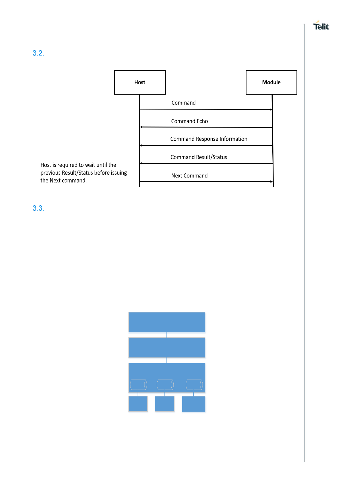
Working Principle
Following representation shows the communication between the Host and the WE310F5-X module:
Figure 1: Communication between the Host and the Module
System Initialization
Upon startup the serial to wireless interface performs the following actions:
- During the initialization process, the module software tries to fetch the configuration file (also
called as profile) from the file system. If the profile is not found, it sets the factory default values to
profile and creates the file in the file system.
For a default profile, the interface starts in the AP mode, initializing the provisioning software.
User can either configure the module through the provisioning mechanism or can issue
commands to start in Station mode and join the intended AP.
- In the profile, configuration related to wireless network- UDP/TCP/DNS/MDNS/HTTP/MQTT are
kept. If the auto connection mode is set, then the module will attempt to join the wireless network
and tries to open connection based on the UDP/TCP/HTTP/MQTT configuration. It configures the
services and fetches based on the MDNS configuration.
- Serial to wireless application is initialized based on the profile settings.
Following diagram represents the sequence of communication between the interfaces:
SPI
Driver
SDIO
Driver
UART
Driver
AT Command Parser
Command Processor
SPI
Drv Ctx
UART
Drv Ctx
SDIO
Drv Ctx
Driver Interface
Figure 2: Serial to Wireless Application
Serial to Wireless application takes command input from three different IOs. The software configurations
can be by either UART and SPI or UART or SDIO combinations. The driver interface gives a transparent
Page 22
WE310F5-X AT Command Reference Guide
80664ST11034A Rev. 4 Page 22 of 174 2020-08-25
interface to the AT command parser. AT command parser does the parsing and calls the command
processor API to process the command.
Note: Current release does not support SPI and SDIO interface.
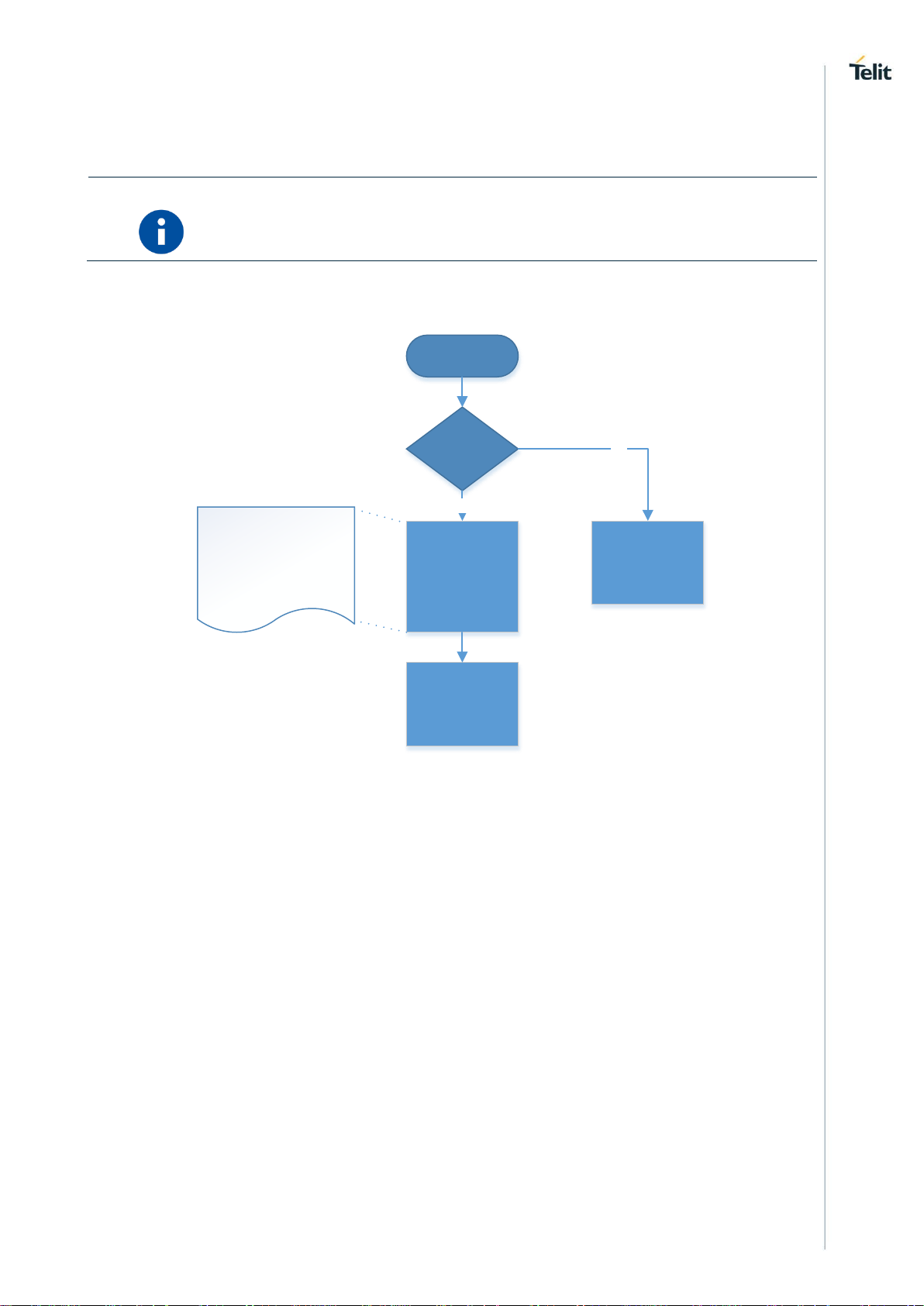
3.3.1. Auto Connection
Start
Auto mode
enable
Configure the
module based on
the saved profile
and indicate to user
about the result of
the configuration
Wait for user
command
Wait for user
command
YES
NO
- Configures L2 and L3
connection indicate the result
- Configure UDP/TCP and
indicates to user
- Configures mDNS and
indicates to user
Page 23
WE310F5-X AT Command Reference Guide
80664ST11034A Rev. 4 Page 23 of 174 2020-08-25
4. HOST INTERACTION
Interface
An embedded host uses one of the serial IO interfaces to connect to the module.
By default, UART0 interface is enabled. When the module boots up, it initializes the UART0 interface to
receive command. Host can enable the second interface by issuing AT command (e.g. AT+YSIF = 1). The
second interface supported can be either SPI or SDIO. Both SPI and SDIO supports Slave mode.
By default, the second interface is disabled. User can enable and save it in profile for the next boot where
the module automatically starts the second interface. Upon factory reset, the second interface is disabled.
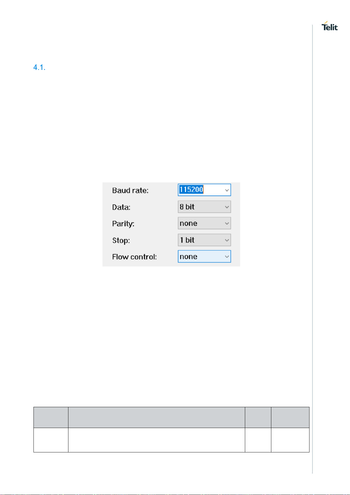
4.1.1. UART
The UART0 is enabled by default. User can configure the UART port with the below shown configuration.
Both UART0 and UART1 takes AT command but UART1 displays debug logs along with the AT command
response.
By default, HW flow control is disabled. User can enable HW flow control by issuing AT&K command for
UART0.
The hardware flow control on UART1 is not supported.
4.1.1.1. Baud Rate - B
Description
This command is used to configure UART and set the UART parameters.
Pre-requisites
None.
Syntax
ATB=<Port>,<Baud rate>,[<Bits per character>,<Parity mode>,<Stop bits>]
Parameters Description
Paramete
r
Value
Forma
t
Descriptio
n
Port
Range: 0,1
Integer
It specifies
port of the
UART to be
Page 24

WE310F5-X AT Command Reference Guide
80664ST11034A Rev. 4 Page 24 of 174 2020-08-25
configured,
where:
0 - High
Speed
UART,
1 - Debug
UART.
Baud rate
Range:
300,600,1200,2400,4800,9600,14400,19200,38400,57600,11520
0
Integer
It specifies
rate at
which the
data
transmits
over a
channel,
port 0
supports
300 to
921600
baud rate
and port 1
supports
only
115200
baud rate.
Bits per
character
Range: 5-8
Default: 8
Integer
It specifies
the bits per
character.
Parity
mode
Range: 0-2
Default: 0
Integer
It specifies
the parity
mode being
used,
where:- 0 is
No Parity, 1
is odd
Parity and 2
is Even
Parity.
Stop bits
Range: 1,3
Default: 1
Integer
It specifies
the number
of stop bits,
where:- 1
for 1 bit and
3 for 2 bits.
Status
For all possible status responses refer Table 4: Status Responses
Example
ATB=0,115200,3,0,1
OK
4.1.1.2. Hardware Flow Control - &Kn
Description
Page 25

WE310F5-X AT Command Reference Guide
80664ST11034A Rev. 4 Page 25 of 174 2020-08-25
This command is used to enable or disable the hardware flow control for UART interface.
Pre-requisites
None.
Syntax
AT&Kn
Parameters Description
Parameter
Value
Format
Description
n
Range: 0,3
Integer
It specifies state of the hardware flow control for
UART interface, where:
3-Enables hardware flow control,
0-Disables hardware flow control.
Status
For all possible status responses refer Table 4: Status Responses
Example
AT&K0
OK
Following command is used to get the status of the hardware flow control in UART interface:
Syntax
AT&K?
Response
&K:<mode>
Response Parameters Description
Parameter
Range
Type
Description
mode
0,3
Integer
It returns 0 or 3, if the
HW flow control is
disabled or enabled
respectively.
Status
For all possible status responses refer Table 4: Status Responses
Example
AT&K?
&K:0
OK
Page 26

WE310F5-X AT Command Reference Guide
80664ST11034A Rev. 4 Page 26 of 174 2020-08-25
5. GENERAL OPERATIONS
System Settings
For basic module setting and to get system information, the following AT commands are used:
• ATEn - To enable/disable echo mode
• ATVn – To enable/disable verbose mode
• AT+YSR – To perform a software reset on the board
• AT+YHD – To get heap information
• AT+YTIME – To set and get time
To store information in the internal Flash of the module, file system commands are used. User can
open/create, read/write and close the file after the completion of specific operation and then delete the file
if not required or not in use.
For a file to be saved in secure mode, a password can be provided during file open procedure. If a
secured file is opened with a wrong password or without a password, then file read operation will give junk
data. User must track and maintain the password of the files saved in secured mode.
User can list the files present in the internal flash and get information on the size of each file.
5.1.1. Echo Mode - En
Description
This command enables or disables Echo mode. In UART interface, echo mode is enabled by
default and in SPI and SDIO interface, echo mode is disabled.
Pre-requisites
None.
Syntax
ATEn
Parameters Description
Parameter
Value
Format
Description
n
Range: 0-1
Integer
It specifies the state of echo mode, where:
1-Enables Echo mode,
0-Disables Echo mode.
Status
For all possible status responses refer Table 4: Status Responses
Example
ATE0
OK
5.1.2. Verbose Mode - Vn
Description
This command enables or disables Verbose mode.
Pre-requisites
None.
Page 27

WE310F5-X AT Command Reference Guide
80664ST11034A Rev. 4 Page 27 of 174 2020-08-25
Syntax
ATVn
Parameters Description
Parameter
Value
Format
Description
n
Range: 0-1
Integer
It specifies the state of Verbose mode, where:
1-Enables Verbose mode
0-Disables Verbose mode.
Status
For all possible status responses refer Table 4: Status Responses
Example
ATV1
OK
5.1.3. File System
5.1.3.1. File Open - +YFOP
Description
This command opens a specified file with the given option.
Pre-requisites
None.
Syntax
AT+YFOP=<Name>,<Option>,[<Password>]
Parameters Description
Parameter
Value
Format
Description
Name
Range: 1-64
String
It specifies the file name along with the path.
Ex:/sys/abc.txt
Option
Range: 0x00x2, 0x41,
0x42, 0xC1,
0xC2, 0x241,
0x242, 0x441,
0x442, 0x4C1,
0x4C2
Hexadecimal
It specifies the options for Open flag, following are
the options:
0x0 to Open in read only mode.
0x1 to Open in write only mode.
0x2 to Open in read and write mode.
In addition to the above flags, any of the following
flags can be bitwise "OR"ed:
0x400 APPEND: - Data written will be appended to
the end of the file. The file operations will always
adjust the position pointer to the end of the file.
0x40 CREAT: - Create the file if it does not exist.
0x80 EXCL: - Used with CREAT. If the file already
exists, then fail, and return error.
Page 28

WE310F5-X AT Command Reference Guide
80664ST11034A Rev. 4 Page 28 of 174 2020-08-25
0x200 TRUNC: - If the file already exists then
discard its previous contents, reducing it to an
empty file.
Password
Range: 16
Default:
String
It specifies the password for a secured file,
supported each time to open a file. If the password
is not necessary to open a file, then it is a unsecure
file.
Response
+YFOP:<File Descriptor>
Response Parameters Description
Parameter
Range
Type
Description
File Descriptor
0X0-0XFFFFFFFF
Hexadecimal
It specifies the file
descriptor in use for
other file operations.
Status
For all possible status responses refer Table 4: Status Responses
Example
AT+YFOP="/abc.txt",42,"TelitIndiaPvtLtd"
+YFOP:1006E6A0
OK
5.1.3.2. File Close - +YFCL
Description
This command closes a specified file.
Pre-requisites
A file must be open before issuing this command.
Syntax
AT+YFCL=<File Descriptor>
Parameters Description
Parameter
Value
Format
Description
File Descriptor
Range: 0X00XFFFFFFFF
Hexadecimal
It specifies the return value while opening the file.
Status
For all possible status responses refer Table 4: Status Responses
Example
AT+YFCL=0
OK
Page 29

WE310F5-X AT Command Reference Guide
80664ST11034A Rev. 4 Page 29 of 174 2020-08-25
5.1.3.3. File Read - +YFRD
Description
This command reads the specified number of bytes of a file from a given offset and the start of the
file.
Pre-requisites
A file must be open before issuing this command.
Syntax
AT+YFRD=<File Descriptor>,[<Offset>],<Length>
Parameters Description
Parameter
Value
Format
Description
File Descriptor
Range: 0X00XFFFFFFFF
Hexadecimal
It specifies the return value while opening a file.
Offset
Range: -116384
Default: -1
Integer
It specifies the offset of the file to start.
If the change in offset value is not required then the
offset value is -1, else it is 0-4096 for any valid
offset value.
If the offset value is not given then by default -1 in
taken as the offset.
Length
Range: 116384
Integer
It specifies the data to be sent with a gap of
~10msec before sending the data.
Response
+YFRD:<File Descriptor>,<Requested Length>,Available Length>,<Data>
Response Parameters Description
Parameter
Range
Type
Description
File Descriptor
0X0-0XFFFFFFFF
Hexadecimal
It specifies the File
Descriptor.
Requested length
1-4294967295
Integer
It specifies the length
requested by user
Available length
1-4294967295
Integer
It specifies the length of
data following
Data
1-4294967295
Binary Data
It specifies the data to
be sent.
Status
For all possible status responses refer Table 4: Status Responses
Example
Page 30

WE310F5-X AT Command Reference Guide
80664ST11034A Rev. 4 Page 30 of 174 2020-08-25
Example1:
AT+YFRD=0,0,5
+YFRD=0,5,5,abcde
OK
Example2:
If the file size is 4224 and the user request a read command for 4500 bytes, then
AT+YFRD=0,4500
+YFRD:0,4500,1024,<data of 1024 bytes>
+YFRD:0,4500,1024,<data of 1024 bytes>
+YFRD:0,4500,1024,<data of 1024 bytes>
+YFRD:0,4500,1024,<data of 1024 bytes>
+YFRD:0,4500,128,<data of 128 bytes>
OK
5.1.3.4. File Write - +YFWR
Description
This command writes in a specified file from a given offset.
Pre-requisites
A file is required to be open before issuing this command.
Syntax
AT+YFWR=<File Descriptor>,[<Offset>],<Data length>,<Data>
Parameters Description
Parameter
Value
Format
Description
File Descriptor
Range: 0X00XFFFFFFFF
Hexadecimal
It specifies the return value while opening a file.
Offset
Range: -116384
Default: -1
Integer
It specifies the offset of the file to start.
If the change in offset value is not required then the
offset value is -1, else it is 0-4096 for any valid
offset value.
If the offset value is not given then by default -1 in
taken as the offset.
Data length
Range: 14294967295
Integer
It specifies the data to be sent with a gap of
~10msec before sending the data.
Data
Range: 14294967295
Binary Data
It specifies the data to be sent.
Status
For all possible status responses refer Table 4: Status Responses
Page 31

WE310F5-X AT Command Reference Guide
80664ST11034A Rev. 4 Page 31 of 174 2020-08-25
Example
AT+YFWR=0,5,5,fghij
OK
5.1.3.5. File Length - +YFLN
Description
This command is used to get the actual file length and the space occupied in FLASH. If the file is
secure, then it adds more bytes to the actual data written by the user.
Pre-requisites
The file should to be present in file system.
Syntax
AT+YFLN=<Name>
Parameters Description
Parameter
Value
Format
Description
Name
Range: 0-64
String
It specifies the file name along with the path.
Response
+YFLN:<Actual file size>,<Total file size<
Response Parameters Description
Parameter
Range
Type
Description
Actual file size
0-4096
Integer
It specifies the actual file
size in the flash, if the
file is secure then it
adds more bytes to the
actual data written by
the user. If the file is still
open then the actual
size may come lesser
then the data written to
the file, as the last flash
write happens when we
close the file.
Total file size in FLASH
0-4096
Integer
It specifies the total file
size occupied in the
flash.
Status
For all possible status responses refer Table 4: Status Responses
Example
AT+YFLN="/abc.txt"
+YFLN:55,1024
OK
Page 32

WE310F5-X AT Command Reference Guide
80664ST11034A Rev. 4 Page 32 of 174 2020-08-25
5.1.3.6. File List - +YFLS
Description
This command lists all the files in the specified path.
Pre-requisites
The path of the file should be present in the Flash.
Syntax
AT+YFLS=[<Path>]
Parameters Description
Parameter
Value
Format
Description
Path
Range: 0-64
Default:
String
It specifies the location of the file.
Response
+YFLS:<File Name>,<Actual file size>,<Total file size in the FLASH>
Response Parameters Description
Parameter
Range
Type
Description
File name
0-64
String
It specifies the file name
with the path.
Actual file size
0-4096
Integer
It specifies the actual
size of the file in bytes.
If the file is secure, then
it adds more bytes to
the actual data written
by the user.
Total file size in flash
0-4096
Integer
It specifies the space
occupied by the file in
flash in bytes.
Status
For all possible status responses refer Table 4: Status Responses
Example
AT+YFLS="/abc"
+YFLS:/abc/xyz.txt,55,1024
+YFLS:/abc/def.txt,110,1024
OK
5.1.3.7. File Delete - +YFRM
Description
This command deletes or removes a specified file from the file system.
Pre-requisites
Page 33

WE310F5-X AT Command Reference Guide
80664ST11034A Rev. 4 Page 33 of 174 2020-08-25
A file should be present in the file system before issuing this command.
Syntax
AT+YFRM=<File name>
Parameters Description
Parameter
Value
Format
Description
File name
Range: 1-64
String
It specifies the file to remove or delete.
Status
For all possible status responses refer Table 4: Status Responses
Example
AT+YFRM="/abc.txt"
OK
Profile Settings
Following are the set of AT commands for profile setting:
• Profile Read - Zn
• Profile Set - &Yn
• Profile Save - &Wn
• Profile Clear/Factory Reset - &F
The configuration parameter values that define the behaviour of the node are grouped into Profiles. These
profiles are stored in non-volatile memory when not in use. The node supports two Profiles by default
(profile0 and profile1).
To save the configuration in flash user must issue AT&Wn (where, n can take 0/1 value based on profile0
and profile1). The profile parameters are saved in JSON format in the file system.
Following AT commands are executed for reading, setting default and saving the current profile:
• ATZn - To read parameters, from the specified profile. Upon execution of this command, module
displays the profile (profile 0, or profile 1) parameters.
• AT&Yn - This command is used to select the default profile. The settings from the profile that are
chosen as the default profile are loaded from non-volatile memory, when the device starts.
• AT&Wn - This command is used to save the current profile. Upon execution of this command, the
current configuration settings are stored in non-volatile memory under the specified profile (profile
0, or profile 1).
5.2.1. Profile Read - Zn
Description
This command reads the profile from Flash.
Pre-requisites
None.
Syntax
ATZn
Parameters Description
Page 34

WE310F5-X AT Command Reference Guide
80664ST11034A Rev. 4 Page 34 of 174 2020-08-25
Parameter
Value
Format
Description
n
Range: 0-1
Integer
It specifies the Profile number to be read.
Response
+ZN:<Profile>
Response Parameters Description
Parameter
Range
Type
Description
Profile
0-65575
String
It specifies the profile
details in JSON format.
Status
For all possible status responses refer Table 4: Status Responses
Example
ATZ0
Zn:""profile":{"s2w_cfg":{"app_type":0,"echo":1,"verbos":1,"auto_mode":0,"second_if":2,"slp":1,"dat
a_mode_cfg":{"proto":0,"index":0},"legacy_params_cfg":{"async_event_flag":0,"psk_valid":0,"wrxps_flag":
1,"security_type":0,"ncmAutoLvl":0,"bulkTxEnable":0}},"system":{"wlan_mode":0,"wlan_domain":0,"sta_cfg
":{"wlan":[{"enable":0,"ssid":"Telit_Guest","pwd":"********","phy_mode":"AGN","auth":0,"enc":0,"channel":1,"
txrate":16}],"power_save":{"enable":1,"idle_period":200,"dtim_policy":3,"ps_poll_num":100,"num_tx_to_wa
keup":0},"ip":{"flag":2,"ipv4":"192.168.240.1","ip_subnet":"255.255.255.0","ip_gw":"192.168.240.1","ip_dns
1":"0.0.0.0","ip_dns2":"0.0.0.0"},"scan_cfg":{"fast_scan_interval":20,"fast_scan_duration":10,"slow_scan_i
nterval":5},"roaming_cfg":{"enable":0,"rssi_low_threshold":65446,"rssi_high_threshold":65516,"poll_time":
30,"force_fg_scan":10,"home_dwell_time":10,"force_scan_interval":30,"scan_type":0,"num_of_channel":6,
"channel_list":[1,3,6,9,11,0,0,0,0,0]},"eap_security_conf":{"enable":0,"method":0,"username":"","password"
:"","identifier":""}},"ap_cfg":{"ap_wlan_cfg":{"mac":"00:00:00:00:00:00","ssid":"Telit_AP","pwd":"********","ph
y_mode":"AGN","channel":6,"auth":4,"enc":3,"hidden_mode":0,"beacon_interval":100,"dtim":3,"inactivity_p
eriod":1,"wps_flag":0},"ip":{"flag":1,"ipv4":"192.168.3.2","ip_subnet":"255.255.255.0","ip_gw":"192.168.3.1"
},"ap_dhcp_cfg":{"start_ip":"192.168.3.3","end_ip":"192.168.3.24","lease_time_ms":86400000}},"mdns_cfg
":{"enable":0,"mdns_host_cfg":{"host_name":""}},"uart_cfg":[{"enable":1,"port":1,"baud":115200,"parity":0,"
stop_bits":1,"char_bits":3,"loopback":0,"flow_ctrl":0},{"enable":1,"port":0,"baud":115200,"parity":0,"stop_bit
s":1,"char_bits":3,"loopback":0,"flow_ctrl":0}],"dbg_cfg":{"enable":0,"debug_config":{"enableCI":0,"buffer_si
ze":1024,"log_level":4}},"xfp_config":{"xfp_enable_in":0,"xfp_port_in":0},"sntp_cfg":{"sntp_enable_in":0,"sn
tp_server_id_in":0,"sntp_server_name_in":0,"sntp_svr_poll_interval_in":0},"ncm_retry_cfg":{"scan_retry_c
ount":3,"scan_retry_time_delay":1500,"dhcp_retry_count":3,"dhcp_retry_time_delay":5000,"tcp_retry_cou
nt":3,"tcp_retry_time_delay":15},"httpd_cfg":{"enable":0,"httpd_cfg_in":{"interface name":"","mode":0,"http
port":0,"https port":0,"family":0,"server name":"","authentication":0,"certificate
name":"","username":"","password":""}}}}"
OK
5.2.2. Profile Set - &Yn
Description
This command sets a profile to the specified profile number which is used in auto configuration
mode.
Pre-requisites
None.
Page 35

WE310F5-X AT Command Reference Guide
80664ST11034A Rev. 4 Page 35 of 174 2020-08-25
Syntax
AT&Yn
Parameters Description
Parameter
Value
Format
Description
n
Range: 0-1
Integer
It specifies the profile number to be set.
Status
For all possible status responses refer Table 4: Status Responses
Example
AT&Y0
OK
5.2.3. Profile Save - &Wn
Description
This command saves the profile to Flash in JSON format.
Pre-requisites
None.
Syntax
AT&Wn
Parameters Description
Parameter
Value
Format
Description
n
Range: 0-1
Integer
It specifies the profile number to save.
Status
For all possible status responses refer Table 4: Status Responses
Example
AT&W0
OK
5.2.4. Profile Clear/Factory Reset - &F
Description
This command resets the profile to factory setting.
Pre-requisites
None.
Syntax
AT&F
Status
Page 36

WE310F5-X AT Command Reference Guide
80664ST11034A Rev. 4 Page 36 of 174 2020-08-25
For all possible status responses refer Table 4: Status Responses
Example
AT&F
OK
Serial2Wireless APP
Real Time Clock (RTC) Settings
System has a real time clock. The time can be set and get from it. The time is kept till the power is
supplied to the system, across different power save mode.
Upon power on, the RTC sets the default time to 01/01/2000,00:00:00+05. User must configure the time to
the correct value manually issuing the AT command or user can start NTP to get the time from the NTP
server.
Once the device boots up, the system time would set to a default value and the time starts running. If the
user sets the time, then the current running time will be updated with the time given as input by issuing
this command.
5.3.1. Time Settings - +YTIME
Description
This command is used to set and get time from the RTC module in Julian format. To get the
system Time, it is to be set once.
Pre-requisites
None.
Syntax
AT+YTIME=<Absolute Time>
Parameters Description
Parameter
Value
Format
Description
Absolute Time
Range: 1-32
String
It specifies the absolute time to be set in Julian
format.
Status
For all possible status responses refer Table 4: Status Responses
Example
AT+YTIME="09/01/2018,11:15:00+04"
OK
Following command is used to get time from RTC module:
Syntax
AT+YTIME?
Response Parameters Description
Parameter
Range
Type
Description
Page 37

WE310F5-X AT Command Reference Guide
80664ST11034A Rev. 4 Page 37 of 174 2020-08-25
time
String
It specifies the UTC time
in Julian format.
Status
For all possible status responses refer Table 4: Status Responses
Example
AT+YTIME?
+YTIME:"01/01/2000,02:00:45+05"
Heap Information - +YHD
Description
This command gets information on total heap size and the memory available for allocation. The
memory available for allocation is in fragments which results in malloc function to fail, though the
requested memory to allocate is less than the available memory.
Pre-requisites
None.
Syntax
AT+YHD
Response
+YFD:<Total heap size>,<Free memory>
Response Parameters Description
Parameter
Range
Type
Description
Total heap size
0-204800
Integer
It specifies the total
heap size.
Free memory
0-204800
Integer
It specifies the total
available free memory in
heap.
Status
For all possible status responses refer Table 4: Status Responses
Example
AT+YHD
+YFD:102400,9024
OK
Reset - +YSR
Description
This command performs a soft reset.
Pre-requisites
None.
Page 38

WE310F5-X AT Command Reference Guide
80664ST11034A Rev. 4 Page 38 of 174 2020-08-25
Syntax
AT+YSR
Status
For all possible status responses refer Table 4: Status Responses
Example
AT+YSR
OK
Serial2Wireless APP
Manufacturer's Name - +CGMI
Description
This command reads the manufacturer's name.
Pre-requisites
None.
Syntax
AT+CGMI
Response
<Manufacturer Name>
Response Parameters Description
Parameter
Range
Type
Description
Manufacturer Name
String
It specifies the
manufacturer's name.
Status
For all possible status responses refer Table 4: Status Responses
Example
AT+CGMI
Telit
OK
Module Name - +CGMM
Description
This command reads the name of the Module.
Pre-requisites
None.
Syntax
AT+CGMM
Response
<Module Name>
Page 39

WE310F5-X AT Command Reference Guide
80664ST11034A Rev. 4 Page 39 of 174 2020-08-25
Response Parameters Description
Parameter
Range
Type
Description
Module Name
7
String
It specifies name of the
module.
Status
For all possible status responses refer Table 4: Status Responses
Example
AT+CGMM
WE310F5
OK
Modem Version - +CGMR
Description
This command reads the version number of the Modem.
Pre-requisites
None.
Syntax
AT+CGMR
Response
<Modem Version>
Response Parameters Description
Parameter
Range
Type
Description
Modem Version
10
String
It specifies the current
modem version.
Status
For all possible status responses refer Table 4: Status Responses
Example
AT+CGMR
M0G.000003
OK
Package Version - #SWPKGV
Description
This command reads all the available version details of the package.
Pre-requisites
None.
Page 40

WE310F5-X AT Command Reference Guide
80664ST11034A Rev. 4 Page 40 of 174 2020-08-25
Syntax
AT#SWPKGV
Response
<Module Version>, <Modem Version>, <Package Version>, <Application Version>, <Source Code
Version>
Response Parameters Description
Parameter
Range
Type
Description
Module Version
20-25
String
It specifies the current
Wi-Fi software version
of the module.
Modem Version
10
String
It specifies the current
version of the modem.
Package Version
10
String
It specifies current
version of the software
package.
Application Version
10
String
It specifies current Telit
application version.
Source Code Version
10
String
It specifies the version
of ADC source code.
BLE FW Version
10
String
It specifies current BLE
software version of the
module.
Status
For all possible status responses refer Table 4: Status Responses
Example
AT#SWPKGV
39.00.000-B005-P0G.000000
M0G.000003
P0G.000000
A0G.000002
R0G.060203
B0G.000002
OK
Version - +YVER
Description
This command is used to get the version number of the software.
Pre-requisites
None.
Page 41

WE310F5-X AT Command Reference Guide
80664ST11034A Rev. 4 Page 41 of 174 2020-08-25
Syntax
AT+YVER
Response
+YVER:<VERSION>
Response Parameters Description
Parameter
Range
Type
Description
Version
9-14
String
It specifies the Version
number of software.
Status
For all possible status responses refer Table 4: Status Responses
Example
AT+YVER
+YVER:"39.00.000-B005"
OK
Page 42

WE310F5-X AT Command Reference Guide
80664ST11034A Rev. 4 Page 42 of 174 2020-08-25
6. NETWORK CONNECTION MANAGER
Wireless Network Connection Manager (WNCM)
NCM supports commands to set the module in Station mode and to connect to a configured Wi-Fi
network. It does L2 and L3 level connection.
It also supports commands to create a network - initializes the AP mode and enable DHCP server to
assign IP address to the connecting devices. Commands to configure station and AP mode is also
supported. Station mode and AP mode can be configured to run simultaneously.
Following is the sequential execution of the AT commands:
1. AT+WNI
2. AT+WNCN
3. AT+WNIPC
4. AT+WNAPC
5. AT+WNAPIPC
6. AT+WNCR
7. AT+WNDC
8. AT+WNIFCFG
9. AT+WNAPST
10. AT+WNSTAST
11. AT+WNASTINFO
Sequential execution in Station mode:
AT+WNI=0
AT+WNIPC [By default the IP configuration will be through DHCP] is not needed
or
AT+WNIPC=1,2,,,,”hostname”[setting hostname with DHCP enabled]
or
AT+WNIPC=1,1,192.168.45.3,255.255.255.0,192.168.45.1,”hostname” [setting static IP and hostname]
AT+WNCN=1,”test_ap”,”12345678”
Sequential execution in AP mode:
AT+WNI=1
AT+WNAPC=0,1,200,3,0
AT+WNIPC=0,1,192.168.45.3,255.255.255.0,192.168.45.1
AT+WNAPIPC=0,192.168.45.4,192.168.45.25,86400000
AT+WNCR=0,”telit_ap”,6,”WPA2”,”AES”,”12345678”
6.1.1. NCM Initialize - +WNI
Description
This command initializes the NCM module and the WLAN module internally.
Pre-requisites
None
Syntax
AT+WNI=<Mode>
Parameters Description
Page 43

WE310F5-X AT Command Reference Guide
80664ST11034A Rev. 4 Page 43 of 174 2020-08-25
Parameter
Value
Format
Description
Mode
Range: 0-1
Integer
It specifies the mode of the NCM module, where:
0-Enables Station mode,
1-Disables AP mode.
Response
+WNI:<WHandle>
Response Parameters Description
Parameter
Range
Type
Description
WHandle
0-1
Integer
It specifies the handle
which used in the next
NCM AT commands.
Status
For all possible status responses refer Table 4: Status Responses
Example
AT+WNI=1
+WNI:0
OK
6.1.2. NCM De-initialize - +WNDI
Description
This command is used to de-initialize the NCM module.
Pre-requisites
AT+WNDC command should be issued, provided the device is in connected state.
Syntax
AT+WNDI=<WHandle>
Parameters Description
Parameter
Value
Format
Description
WHandle
Range: 0-1
Integer
It specifies the WHandle obtained after issuing
AT+WNI command.
Status
For all possible status responses refer Table 4: Status Responses
Example
AT+WNDI=1
OK
Page 44

WE310F5-X AT Command Reference Guide
80664ST11034A Rev. 4 Page 44 of 174 2020-08-25
6.1.3. Configure Station Mode - +WNSTAC
Description
This command sets the Station mode configurations. It should be issued before AT+WNCN
command, else default values are taken.
Pre-requisites
AT+WNI=0 command should be issued.
Syntax
AT+WNSTAC=<WHandle>,[<Listen interval>,<Keep alive interval>,<WPS flag>,<Method>,<Pin>]
Parameters Description
Parameter
Value
Format
Description
WHandle
Range: 0-1
Integer
It specifies the WHandle obtained after issuing
AT+WNI command.
Listen interval
Range: 1-50
Default: 1
Integer
It specifies the listen interval in station mode in
number of beacon intervals.
Keep alive
interval
Range: 0-255
Default: 0
Integer
It specifies the keep alive interval in STA mode
after connection in seconds.
WPS flag
Range: 0-1
Default: 0
Integer
It specifies the WPS support in Station mode,
where:
0-Disables WPS support,
1-Enables WPS support.
If WPS flag is enabled, then the module uses WPS
method to join the network by executing the
command AT+WNCN. Also, the SSID in the
command AT+WNCN is not necessary to provide.
Method
Range: 0-1
Default: 1
Integer
It specifies the method used for WPS procedure,
where:
0-for PIN method,
1-for PUSH method.
Pin
Range: 8
Default: N/A
String
It specifies the pin used in WPS PIN method during
the parameter "Method" selection.
Status
For all possible status responses refer Table 4: Status Responses
Example
AT+WNSTAC=1,100,0,0,0
OK
Following command is used to get the STA related configurations.
Syntax
Page 45

WE310F5-X AT Command Reference Guide
80664ST11034A Rev. 4 Page 45 of 174 2020-08-25
AT+WNSTAC?
Response
+WNSTAC:<Listen interval>, <Keep alive interval>, <WPS support>, <WPS method>, <Pin>
Response Parameters Description
Parameter
Range
Type
Description
Listen interval
1-50
Integer
It specifies the value of
the current listen interval
in Station mode in
number of beacon
intervals.
Keep alive interval
0-255
Integer
It specifies the value of
the current keep alive
interval in Station mode
in seconds.
WPS support
0-1
Integer
It specifies the method
used for WPS support in
STA mode.
Method
0-1
Integer
It specifies the method
used for WPS
procedure. This value is
considered only when
WPS support in
enabled.
Pin
N/A
String
It specifies the current
value of the pin in WPS
pin method.
Status
For all possible status responses refer Table 4: Status Responses
Example
AT+WNSTAC?
+WNSTAC:100,0,0,0,""
OK
6.1.4. Configure AP Mode - +WNAPC
Description
This command sets the AP configurations. It must be executed before AT+WNCR command, else
will take default values.
Pre-requisites
AT+WNI=1 command is mandatory.
Syntax
AT+WNAPC=<WHandle>,[<Hidden SSID>,<Beacon Interval>,<DTIM Period>,<WPS>]
Parameters Description
Page 46

WE310F5-X AT Command Reference Guide
80664ST11034A Rev. 4 Page 46 of 174 2020-08-25
Parameter
Value
Format
Description
WHandle
Range: 0-1
Integer
It specifies the WHandle obtained after issuing
AT+WNI command.
Hidden SSID
Range: 0-1
Default: 0
Integer
It specifies the hidden SSID flag for a network.
0 - disables the hidden SSID
1 - enables the hidden SSID
Beacon
Interval
Range: 1001000
Default: 100
Integer
It specifies the interval between the beacon frames
in TU (unit of time equal to 1024 microseconds).
DTIM Period
Range: 1-255
Default: 3
Integer
It specifies the DTIM (Delivery Traffic Indication
Map) count.
WPS
Range: 0-1
Default: 0
Integer
It specifies the WPS support for a network, where:
0-Disables WPS,
1-Enables WPS.
Status
For all possible status responses refer Table 4: Status Responses
Example
AT+WNAPC=0,0,100,3,1
OK
Following command is used to get the AP related configurations.
Syntax
AT+WNAPC?
Response
+WNAPC:<Hidden SSID>, <Beacon Interval>, <DTIM Period>, <WPS support>
Response Parameters Description
Parameter
Range
Type
Description
Hidden SSID
0-1
Integer
It specifies the status of
hidden SSID feature in
AP mode.
Beacon Interval
100-1000
Integer
It specifies the current
beacon interval value in
AP mode.
DTIM Period
1-255
Integer
It specifies the current
DTIM count in AP mode.
WPS support
0-1
Integer
It specifies the current
WPS support in AP
mode.
Page 47

WE310F5-X AT Command Reference Guide
80664ST11034A Rev. 4 Page 47 of 174 2020-08-25
Status
For all possible status responses refer Table 4: Status Responses
Example
AT+WNAPC?
+WNAPC:0,100,3,0
OK
6.1.5. Configure IP Address in AP Mode - +WNAPIPC
Description
This command sets the DHCP server configuration in AP mode.
Pre-requisites
AT+WNIPC command should be issued.
Syntax
AT+WNAPIPC=<WHandle>,<IP Start Address>,<IP End Address>,<Lease Time>
Parameters Description
Parameter
Value
Format
Description
WHandle
Range: 0-1
Integer
It specifies the WHandle obtained after issuing
AT+WNI command.
IP Start
Address
Range: N/A
IP Address
It specifies the starting IP address allocated to the
connected stations. This address must have the
same network ID as that of the IP address
configured in the At command +WNIPC.
IP End
Address
Range: N/A
IP Address
It specifies the end IP address until which the
connected STAs will get IP addresses. The end IP
address must have the host ID greater than the
host ID given in the start address.
Lease Time
Range: 14294967295
Integer
It specifies the lease time in seconds for the DHCP
server.
Status
For all possible status responses refer Table 4: Status Responses
Example
AT+WNAPIPC=0,192.168.23.24,192.168.23.55,86400000
OK
Following command is used to get the DHCP server configurations of an AP.
Syntax
AT+WNAPIPC?
Response
+WNAPIPC:<IP Start Address>,<IP End Address>,<Lease time>
Page 48

WE310F5-X AT Command Reference Guide
80664ST11034A Rev. 4 Page 48 of 174 2020-08-25
Response Parameters Description
Parameter
Range
Type
Description
IP Start Address
N/A
IP Address
It specifies the current
IP Start address for
DHCP server in AP
mode.
IP End Address
N/A
IP Address
It specifies the current
IP End address for
DHCP server in AP
mode.
Lease time
1-4294967295
Integer
It specifies the current
lease time for DHCP
server in AP mode.
Status
For all possible status responses refer Table 4: Status Responses
Example
AT+WNAPIPC?
+WNAPIPC:192.168.3.5,192.168.3.250,86400000
OK
6.1.6. NCM Create - +WNCR
Description
This command is used to create a network.
Pre-requisites
AT+WNAPIPC command should be issued.
Syntax
AT+WNCR=<WHandle>,<SSID>,<Channel>,<Security Type>,<Encryption Type>,[<PassPhrase>]
Parameters Description
Parameter
Value
Format
Description
WHandle
Range: 0-1
Integer
It specifies the WHandle obtained after issuing
AT+WNI command.
SSID
Range: 1-32
String
It specifies the SSID of the network.
Channel
Range: 1-14
Integer
It specifies the channel number of the network.
Security Type
Range: N/A
String
It specifies the type of security and types are:
"NONE",
"WPA2".
Page 49

WE310F5-X AT Command Reference Guide
80664ST11034A Rev. 4 Page 49 of 174 2020-08-25
Encryption
Type
Range: N/A
String
It specifies the type of encryption and the types are:
"NONE",
"AES".
PassPhrase
Range: 8-64
Default: N/A
String
It specifies the pass phrase for a secured network.
Response
+WNCR:<Create status>
Response Parameters Description
Parameter
Range
Type
Description
Create status
N/A
Not created, Created
It specifies the status of
the AP mode.
Status
For all possible status responses refer Table 4: Status Responses
Example
AT+WNCR=0,"Telit_Guest",6,"WPA","TKIP","12345678"
+WNCR:CREATED
OK
Following command is used to get the status of current AP mode.
Syntax
AT+WNCR?
Response
+WNCR:<Create status>
Response Parameters Description
Parameter
Range
Type
Description
Create status
N/A
Not created, Created
It specifies the status of
the AP mode.
Status
For all possible status responses refer Table 4: Status Responses
Example
AT+WNCR?
+WNCR:CREATED
OK
6.1.7. NCM Connect - +WNCN
Description
This command connects the existing network up to L3 level.
Page 50

WE310F5-X AT Command Reference Guide
80664ST11034A Rev. 4 Page 50 of 174 2020-08-25
Pre-requisites
AT+WNI=0 command is a mandatory. For static IP address, AT+WNIPC command should be
issued.
Syntax
AT+WNCN=<WHandle>,[<SSID>,<PassPhrase>,<Channel>]
Parameters Description
Parameter
Value
Format
Description
WHandle
Range: 0-1
Integer
It specifies the WHandle obtained after issuing
AT+WNI command.
SSID
Range: 1-32
Default: N/A
String
It specifies the SSID of the existing network to
which user wants to connect. If the SSID is NULL,
then the WPS connection happens provided WPS
is enabled.
PassPhrase
Range: 0-64
Default: N/A
String
It specifies the pass phrase required to connect to
a network.
Channel
Range: 1-14
Default: 0
Integer
It specifies the channel of an existing AP to
connect.
Response
+WNCN:<Connect status>,<IP Address>,<Net Mask>,<Gateway>
Response Parameters Description
Parameter
Range
Type
Description
Connect status
N/A
not connected,
connected,
disconnected, DHCP
failed, auto IP done,
new IP
It specifies the current
connection status.
IP Address
N/A
IP Address
It specifies the current
IP Address.
Net Mask
N/A
IPv4 Address
It specifies the current
network mask.
Gateway
N/A
IP Address
It specifies the current
gateway address.
Status
For all possible status responses refer Table 4: Status Responses
Example
AT+WNCN=1,"Telit_Guest","qwerty123456",1
+WNCN:CONNECTED,192.168.0.88,255.255.255.0,192.168.0.1
Page 51

WE310F5-X AT Command Reference Guide
80664ST11034A Rev. 4 Page 51 of 174 2020-08-25
OK
Following command is used to get the connection status up to L3 level:
Syntax
AT+WNCN?
Response
+WNCN:<connect status>,<IP Address>,<Net Mask>,<Gateway>
Response Parameters Description
Parameter
Range
Type
Description
connect status
N/A
not connected,
connected
It specifies status of
connection.
IP Address
N/A
IP Address
It specifies current IP
address
Net Mask
N/A
IPv4 Address
It specifies current
subnet mask.
Gateway
N/A
IP Address
It specifies current
gateway.
Status
For all possible status responses refer Table 4: Status Responses
Example
AT+WNCN?
+WNCN:CONNECTED,192.168.3.45,255.255.255.0,192.168.3.1
OK
Asynchronous Response
+WNCN:<Connect status>,<IP Address>,<Net Mask>,<Gateway>
Asynchronous Response Parameters Description
Parameter
Range
Type
Description
Connect status
N/A
not connected,
connected,
disconnected, DHCP
failed, auto IP done,
new IP
It specifies the current
connection status.
IP Address
N/A
IP Address
It specifies current IP
address.
Net Mask
N/A
IPv4 Address
It specifies current
network mask.
Gateway
N/A
IP Address
It specifies current
gateway address.
Page 52

WE310F5-X AT Command Reference Guide
80664ST11034A Rev. 4 Page 52 of 174 2020-08-25
6.1.8. Get Associated Station Information - +WNASTINFO
Description
This command lists the MAC addresses and IP addresses of stations connected, when device is
in AP mode.
Pre-requisites
AT+WNCR command should be issued.
Syntax
AT+WNASTINFO
Response
+WNASTINFO:<MAC Address>, <IP Address>
Response Parameters Description
Parameter
Range
Type
Description
MAC address
N/A
MAC Address
It specifies the MAC
address of the
connected station.
IP address
N/A
IP Address
It specifies the IP
Address of the
connected station.
Status
For all possible status responses refer Table 4: Status Responses
Example
AT+WNASTINFO
+WNASTINFO:E0:9D:31:13:BB:38,192.168.3.3
OK
6.1.9. Interface Configuration Information - +WNIFCFG
Description
This command is used to get the information of all interfaces.
Pre-requisites
AT+WNI command should be issued.
Syntax
AT+WNIFCFG
Response
+WNIFCFG:<Device ID>, <MAC address>, <State>, <WLAN State>, <Mode>, <BSSID>, <SSID>,
<Channel>, <Security>, <RSSI>, <IP address>, <Subnet address>, <Gateway address>, <DNS1>,
<DNS2>, <DNS3>
Response Parameters Description
Page 53

WE310F5-X AT Command Reference Guide
80664ST11034A Rev. 4 Page 53 of 174 2020-08-25
Parameter
Range
Type
Description
Device ID
0-1
Integer
It specifies the WHandle
of the interface.
MAC address
N/A
MAC Address
It specifies the MAC
address of the interface.
State
N/A
DOWN, UP
It specifies the NCM
status of the interface.
WLAN Status
N/A
NOT CONNECTED,
CONNECTED
It specifies the WLAN
interface status.
Mode
N/A
NONE, STA, AP
It specifies the Mode of
the interface-AP or STA.
BSSID
N/A
MAC Address
It specifies the BSSID of
the network in STA
mode and own MAC
address in AP mode.
SSID
N/A
String
It specifies the SSID of
the network to which
interface is connected in
STA mode and the
SSID of the created
network in AP mode.
Channel
1-14
Integer
It specifies the channel
number of the network
to which interface is
connected in STA mode
and SSID of the created
network in AP mode.
Security
N/A
NONE, WEP, WPA
PSK, WPA
ENTERPRISE, WPA2
PSK, WPA2
ENTERPRISE
It specifies the security
type on both interfaces.
RSSI
N/A
Integer
It specifies the RSSI
value on both interfaces.
IP address
N/A
IP Address
It specifies the current
IP address.
Subnet address
N/A
IP Address
It specifies the current
subnet mask address.
Gateway address
N/A
IP Address
It specifies the current
Gateway address.
DNS1 address
N/A
IP Address
It specifies the current
DNS1 address.
Page 54

WE310F5-X AT Command Reference Guide
80664ST11034A Rev. 4 Page 54 of 174 2020-08-25
DNS2 address
N/A
IP Address
It specifies the current
DNS2 address.
DNS3 address
N/A
IP Address
It specifies the current
DNS3 address.
Status
For all possible status responses refer Table 4: Status Responses
Example
AT+WNIFCFG
+WNIFCFG:0,00:00:00:00:00:00,DOWN,NOT
CONNECTED,NONE,00:00:00:00:00:00,"",0,NONE,0,0.0.0.0,0.0.0.0,0.0.0.0,0.0.0.0,0.0.0.0,0.0.0.0
+WNIFCFG:1,11:22:33:44:55:66, UP, CONNECTED, STA,00:aa:bb:cc:dd:ee, telit_guest, 6,
NONE,192.168.3.45,255.255.255.0,192.168.3.1,192,168.3.1,0.0.0.0,0.0.0.0
OK
6.1.10. NCM Disconnect - +WNDC
Description
This command disconnects from a connected network in station mode or turn down the created
network in AP mode.
Pre-requisites
AT+WNCN in station mode or AT+WNCR in AP mode should be issued.
Syntax
AT+WNDC=<WHandle>
Parameters Description
Parameter
Value
Format
Description
WHandle
Range: 0-1
Integer
It specifies the WHandle obtained after issuing
AT+WNI command.
Response
+WNDC:<Disconnect status>
Response Parameters Description
Parameter
Range
Type
Description
Disconnect status
N/A
not disconnected,
disconnected, down
It specifies the
disconnect status of the
current interface.
Status
For all possible status responses refer Table 4: Status Responses
Example
Page 55

WE310F5-X AT Command Reference Guide
80664ST11034A Rev. 4 Page 55 of 174 2020-08-25
AT+WNDC=1
+WNDC:DISCONNECTED
OK
Page 56

WE310F5-X AT Command Reference Guide
80664ST11034A Rev. 4 Page 56 of 174 2020-08-25
7. WIRELESS DRIVER
Wireless Local Area Network (WLAN)
WLAN supported AT commands gives excellent control on the WLAN driver. Every time the device
connects to a wireless access point, WLAN interface initialization is needed.
Following AT commands are sequentially executed to get information:
1. AT+WI
2. AT+WCCG
3. AT+WMACG
4. AT+WPHYMODEG
5. AT+WREGDG
6. AT+WTXRATEG
7. AT+WRSSIG
8. AT+WS=1,”ssid”, ”channel”
Following AT commands are sequentially executed to set information:
1. AT+WI
2. AT+WBMISSINTS
3. AT+WAPPIE
4. AT+WCCS
5. AT+WPHYMODES
6. AT+WREGDS
7. AT+WTXPOWERS
8. AT+TXRATES
9. AT+WPOWERSAVE
Following AT commands are sequentially executed for sending raw packets:
AT+WI=0
AT+WRAWPKTS=1,1,0,5,6,0,0,,”11:22:33:44:55:66”, “11:22:33:44:55:63”, “11:22:33:44:55:65”,
“11:22:33:44:66:67”
Following AT commands are sequentially executed for STA and AP mode:
Station mode:
AT+WNI=0
AP mode:
AT+WNI=1
AT+WNIPC=0,1,192.168.3.2,255.255.255.0,192.168.3.1
AT+WNAPIPC=0,192.168.3.3,192.168.3.24,86400000
AT+WNCR=0,"test_qca_ap",6,"WPA2","AES","12345678"
7.1.1. Get MAC Address - +WMACG
Description
This command is used to get the MAC address of the WLAN interface.
Pre-requisites
AT+WI or AT+WNI command should be issued.
Syntax
AT+WMACG=<WHandle>
Parameters Description
Page 57

WE310F5-X AT Command Reference Guide
80664ST11034A Rev. 4 Page 57 of 174 2020-08-25
Parameter
Value
Format
Description
WHandle
Range: 0-1
Integer
It specifies the WHandle obtained from AT
command AT+WI or AT+WNI.
Response
+WMACG:<MAC Address>
Response Parameters Description
Parameter
Range
Type
Description
MAC Address
N/A
MAC Address
It specifies the MAC
address of the given
interface.
Status
For all possible status responses refer Table 4: Status Responses
Example
AT+WMACG=1
+WMACG:00:21:7E:24:A6:50
OK
7.1.2. Scan - +WS
Description
This command scans all the channels in the WLAN interface.
Pre-requisites
AT+WNI=0 commands should be issued.
Syntax
AT+WS=<WHandle>,[<SSID>,<Channel>]
Parameters Description
Parameter
Value
Format
Description
WHandle
Range: 0-1
Integer
It specifies the WHandle obtained after issuing
AT+WNI command for STA mode.
SSID
Range: 1-32
Default:
String
It specifies the SSID of the network to scan.
Channel
Range: 1-14
Default: 0
Integer
It specifies the channel to scan.
Response
+WS:<bssid>,<ssid>,<channel>,<type>,<rssi>,<security>
Page 58

WE310F5-X AT Command Reference Guide
80664ST11034A Rev. 4 Page 58 of 174 2020-08-25
Response Parameters Description
Parameter
Range
Type
Description
BSSID
N/A
MAC Address
It specifies the BSSID of
the scanned networks.
SSID
N/A
String
It specifies the SSID of
the scanned networks.
CHANNEL
1-14
Integer
It specifies the channel
number of the scanned
networks.
TYPE
N/A
INFRA, ADHOC
It specifies the network
type of the scanned
networks.
RSSI
N/A
Integer
It specifies the RSSI
value of the scanned
networks.
SECURITY
N/A
NONE, WEP, WPA
PSK, WPA2 PSK,
WPA3
It specifies the security
type of the scanned
networks.
Status
For all possible status responses refer Table 4: Status Responses
Example
AT+WS=1
+WS:CC:B2:55:96:E8:CD,"dirwifi",1,INFRA,-82,WPA2 PSK
+WS:A8:9D:21:A2:E8:62,"Team_a_live",6,INFRA,-91,WPA2 PSK
+WS:68:7F:74:52:6F:D4,"homekit",6,INFRA,-55,NONE
+WS:84:1B:5E:E1:EC:BB,"NETGEAR35-5G",153,INFRA,-75,WPA2 PSK
OK
7.1.3. Scan Time - +WST
Description
This command sets the scan time for scanning.
Pre-requisites
AT+WNI=0 command should be issued.
Syntax
AT+WST=<WHandle>,<Scan time>
Parameters Description
Parameter
Value
Format
Description
WHandle
Range: 0-1
Integer
It specifies the WHandle obtained after issuing
AT+WNI command for STA mode.
Page 59

WE310F5-X AT Command Reference Guide
80664ST11034A Rev. 4 Page 59 of 174 2020-08-25
Scan time
Range: 5-1500
Integer
It specifies the time taken to scan in msec.
Status
For all possible status responses refer Table 4: Status Responses
Example
AT+WST=1000
OK
7.1.4. Set Country Code - +WCCS
Description
This command sets the country code in WLAN interface.
Pre-requisites
AT+WNI command should to be issued.
Syntax
AT+WCCS=<WHandle>,<Country Code>
Parameters Description
Parameter
Value
Format
Description
WHandle
Range: 0-1
Integer
It specifies the WHandle obtained after issuing
AT+WI or AT+WNI command.
Country Code
Range: 2-3
String
It specifies the Country code to be set in WLAN
enabled interface.
Note: Please refer Appendix B - List of Country
Code, for list of countries and its code.
Status
For all possible status responses refer Table 4: Status Responses
Example
AT+WCCS=1,"IN"
OK
7.1.5. Get Physical Mode - +WPHYMODEG
Description
This command gives the physical mode of the WLAN interface.
Pre-requisites
AT+WI or AT+WNI command should be issued.
Syntax
AT+WPHYMODEG=<WHandle>
Parameters Description
Page 60

WE310F5-X AT Command Reference Guide
80664ST11034A Rev. 4 Page 60 of 174 2020-08-25
Parameter
Value
Format
Description
WHandle
Range: 0-1
Integer
It specifies the WHandle obtained after issuing
AT+WI or AT+WNI command.
Response
+WPHYMODEG:<Physical mode>
Response Parameters Description
Parameter
Range
Type
Description
Physical mode
N/A
B, BG, BGN
It specifies the current
physical mode of the
given interface.
Status
For all possible status responses refer Table 4: Status Responses
Example
AT+WPHYMODEG=1
+WPHYMODEG:BGN
OK
7.1.6. Set Physical Mode - +WPHYMODES
Description
This command sets the physical mode of the WLAN interface. WE310 supports only B/BG/BGN
modes
Pre-requisites
AT+WI or AT+WNI command should be issued.
Syntax
AT+WPHYMODES=<WHandle>,<Physical mode>
Parameters Description
Parameter
Value
Format
Description
WHandle
Range: 0-1
Integer
It specifies the WHandle obtained after issuing
AT+WI or AT+WNI command.
Physical mode
Range: 1-3
String
It specifies the physical mode of the WLAN enabled
interface.WE310 supports only "B","BG","BGN"
modes
Status
For all possible status responses refer Table 4: Status Responses
Example
AT+WPHYMODES=1,"BG"
Page 61

WE310F5-X AT Command Reference Guide
80664ST11034A Rev. 4 Page 61 of 174 2020-08-25
OK
7.1.7. Get RSSI - +WRSSIG
Description
This command is used to get the RSSI value of the WLAN interface.
Pre-requisites
AT+WNI=0 and AT+WNCN command should be issued. STA mode should be in connected state.
Syntax
AT+WRSSIG
Response
+WRSSIG:<RSSI value>
Response Parameters Description
Parameter
Range
Type
Description
RSSI value
N/A
Integer
It specifies the RSSI
value of the given
interface.
Status
For all possible status responses refer Table 4: Status Responses
Example
AT+WRSSIG
+WRSSIG:30
OK
7.1.8. Send Raw Packets - +WRAWPKTS
Description
This command is used to send the raw WLAN packets (Beacon, probe req, probe resp, data,
action frames).
The device must be in disassociation state when user sends raw WLAN packets.\b
Combinations of four addresses are:
Beacon Data frame:
addr1 - Transmitter address, source address, BSSID address.
addr2 - Not used.
addr3 - Not used.
addr4 - Not used.
Probe Request:
addr1 - Transmitter address, source address, BSSID address.
Page 62

WE310F5-X AT Command Reference Guide
80664ST11034A Rev. 4 Page 62 of 174 2020-08-25
addr2 - Not used.
addr3 - Not used.
addr4 - Not used.
Probe Response:
addr1 - Not used.
addr2 - Receiver address, Destination address.
addr3 - Transmitter address, source address, BSSID address.
addr4 - Not used.
Data frame:
addr1 - Not used.
addr2 - Receiver address, Destination address, STA address.
addr3 - Transmitter address, source address, BSSID address.
addr4 - Not used.
Action frame:
addr1 - Not used.
addr2 - Receiver address, Destination address.
addr3 - Transmitter address, source address, BSSID address.
addr4 - Not used.
Pre-requisites
AT+WI or AT+WNI command should be issued.
Syntax
AT+WRAWPKTS=<WHandle>,<Rate index>,<Number of tries>,<Channel>,<Packet
type>,<addr1>,<addr2>,<addr3>,[<addr4>],<Data length>,<Payload>
Parameters Description
Parameter
Value
Format
Description
WHandle
Range: 0-1
Integer
It specifies the WHandle obtained after issuing
AT+WI or AT+WNI command.
Rate index
Range: 0-20
Integer
It specifies the data rate in which the WLAN raw
packet are sent. Setting of data rate is not
supported.
Number of tries
Range: 1-14
Integer
It specifies the number of packets that is sent over
the air by WLAN driver.
Page 63

WE310F5-X AT Command Reference Guide
80664ST11034A Rev. 4 Page 63 of 174 2020-08-25
Channel
Range: 1-14
Integer
It specifies the channel in which WLAN raw packets
are sent.
Packet type
Range: 0-4
Integer
It specifies the payload sent in raw WLAN packet,
where:
0-for Beacon,
1-for Probe Request,
2-for Probe Response,
3-for Data frame
4-for Action frame
addr1
Range:
MAC
Address
It specifies the MAC address of addr1 that sends
the raw WLAN packet over the air. The use of
addr1 in different scenarios are as described in the
command description.
addr2
Range:
MAC
Address
It specifies the MAC address of addr2 that sends
the raw WLAN packet over the air. The use of
addr2 in different scenarios are as described in the
command description.
addr3
Range:
MAC
Address
It specifies the MAC address of addr3 that sends
the raw WLAN packet over the air. The use of
addr3 in different scenarios are as described in the
command description.
addr4
Range: N/A
Default:
MAC
Address
It specifies the MAC address of addr4 that sends
the raw WLAN packet over the air. The use of
addr4 in different scenarios are as described in the
command description. This addr is not supported in
WE310F5 module.
Data length
Range: 1-1400
Integer
It specifies the data to be sent with a gap of
~10msec before sending the data.
Payload
Range: 1-1400
Binary Data
It specifies the payload sent in raw WLAN packet
(beacon, QOS data, 4 addr data packet).
Status
For all possible status responses refer Table 4: Status Responses
Example
AT+WRAWPKTS=1,1,10,6,0,00:E0:4C:87:11:07,11:22:33:44:55:63,00:E0:4C:87:11:07,,5,"abcde"
OK
7.1.9. Set Promiscuous Filter - +WPROMISCSETFILTER
Description
This command sets the parameters in the promiscuous filter used for wireless sniffing.
Pre-requisites
AT+WNI=0 command should be issued, as the WE310 module supports promiscuous mode is
STA mode only.
Page 64

WE310F5-X AT Command Reference Guide
80664ST11034A Rev. 4 Page 64 of 174 2020-08-25
Syntax
AT+WPROMISCSETFILTER=<WHandle>,<Filter number>,<Channel>,[<Source MAC
address>,<Destination MAC address>,<Frame type>,<Sub type>]
Parameters Description
Parameter
Value
Format
Description
WHandle
Range: 0
Integer
It specifies the WHandle obtained after issuing
AT+WI or AT+WNI command.
Filter number
Range: 1-3
Integer
It specifies the number of filters; the user sets or
sniffs.
Note: Current release supports only 1 filter.
Channel
Range: 1-14
Integer
It specifies the channel to sniff.
Source MAC
address
Range: N/A
Default: N/A
MAC
Address
It specifies the source MAC address of the filter.
Destination
MAC address
Range: N/A
Default: N/A
MAC
Address
It specifies the destination MAC address of the
filter.
Frame type
Range: 0-2
Default: 0xff
Integer
It specifies the type of the frame.
Sub type
Range: 0-47
Default: 0xff
Integer
It specifies the sub type.
Status
For all possible status responses refer Table 4: Status Responses
Example
at+WPROMISCSETFILTER=0,1,6,00:8e:f2:56:24:04,ff:ff:ff:ff:ff:ff,0,8
OK
7.1.10. Start Promiscuous Mode - +WPROMISCCMD
Description
This command is used to start the device in Promiscuous mode. WE310 module supports
promiscuous mode is STA mode only.
Pre-requisites
AT+WPROMISCSETFILTER command should be issued.
Syntax
AT+WPROMISCCMD=<WHandle>,<Mode>,<Filter number>
Parameters Description
Page 65

WE310F5-X AT Command Reference Guide
80664ST11034A Rev. 4 Page 65 of 174 2020-08-25
Parameter
Value
Format
Description
WHandle
Range: 0-1
Integer
It specifies the WHandle obtained after issuing
AT+WI or AT+WNI command.
Mode
Range: 0-1
Integer
It specifies the mode of the promiscuous filter,
where:
0-Disable,
1-Enable.
Filter number
Range: 1-3
Integer
It specifies the number of filters; the user sets or
sniffs.
Note: Current release supports only 1 filter.
Status
For all possible status responses refer Table 4: Status Responses
Example
AT+WPROMISCCMD=0,1,1
OK
Asynchronous Response
+WPROMISCCMD:<info>
Asynchronous Response Parameters Description
Parameter
Range
Type
Description
info
N/A
String
It displays the captured
packet.
7.1.11. Application Information Element - +WAPPIE
Description
This command adds the application Information Element (IE) to the beacon, probe response
frames in AP mode and probe request frame in Station mode.
In station mode, the application IE and the subsequent probe request will have the IE added by
the user.
In AP mode, create a Network and then issue the command to add the application IE.
Pre-requisites
AT+WI command should be issued.
Syntax
AT+WAPPIE=<WHandle>,<Frame type>,<OUI>,[<Data length>,<Vendor content>]
Parameters Description
Parameter
Value
Format
Description
Page 66

WE310F5-X AT Command Reference Guide
80664ST11034A Rev. 4 Page 66 of 174 2020-08-25
WHandle
Range: 0-1
Integer
It specifies the WHandle obtained after issuing
AT+WI or AT+WNI command.
Frame type
Range: 0-2
Integer
It specifies the driver in which the application IE
frame is set, where:
0-for Beacon,
1-for Probe request,
2-for Probe response
OUI
Range: 0-6
String
It specifies the parameter used to indicate the
WLAN driver with the OUI value of the vendor
specific information element. The input is 6bytes.
Ex: If the OUI value is 5 6A 9D then user must give
05 6A 9D.
Data length
Range: 0-504
Default: N/A
Integer
It specifies the data to be sent with a gap of
~10msec before sending the data.
Vendor content
Range: 0-504
Default: N/A
Binary Data
It specifies the specific content of the vendor in the
Information element.
Status
For all possible status responses refer Table 4: Status Responses
Example
AT+WAPPIE=1,1,"506f9a",4,
OK
Bluetooth Low Energy (BLE)
BLE provides AT commands to discovery of the devices, query of services, and sends information. It is
used for easy sensor integration, configuration (provisioning), management and diagnostics.
Communication between the devices are:
• Central and Peripheral: It determines the role of BLE connection itself. Device in central role –
scans and advertises. Device in peripheral role makes the advertisement.
• GATT server and GATT Client functionality: It determines the type of communication of the
devices, once the connection is set up.
7.2.1. BLE Initialize/De-initialize - +BI
Description
This command is used to initialize/de-initialize BLE stack.
Pre-requisites
None.
Syntax
AT+BI=<START>
Parameters Description
Page 67

WE310F5-X AT Command Reference Guide
80664ST11034A Rev. 4 Page 67 of 174 2020-08-25
Parameter
Value
Format
Description
START
Range: 0-1
Integer
It specifies the initialization/de-initialization of the
BLE stack,
where:
1- Initializes BLE stack,
0- De-initializes BLE stack.
Status
For all possible status responses refer Table 4: Status Responses
Example
To initialize BLE:
AT+BI=1
OK
AT+BI=0
OK
7.2.2. BLE Own Device Address - +BOAD
Description
This command is used to read the Bluetooth device address.
Pre-requisites
AT+BI=1 command should be issued.
Syntax
AT+BOAD
Response
+BOAD:<Bluetooth Device Address>
Response Parameters Description
Parameter
Range
Type
Description
Bluetooth Device
Address
String
It specifies the Bluetooth
device's own device
address.
Status
For all possible status responses refer Table 4: Status Responses
Example
AT+BOAD
+BOAD:"008025123456"
OK
7.2.3. BLE Connect - +BCONNECT
Description
Page 68

WE310F5-X AT Command Reference Guide
80664ST11034A Rev. 4 Page 68 of 174 2020-08-25
This command is used to establish a GATT connection to a peripheral device directly via its
address.
Note: It supports a maximum of 4 connections in central role
Pre-requisites
AT+BI=1 command should be issued.
Syntax
AT+BCONNECT=<Bluetooth Remote Address>,<Bluetooth Address Type>
Parameters Description
Parameter
Value
Format
Description
Bluetooth
Remote
Address
Range: 1-48
String
It specifies the Bluetooth remote device address
(12 hex digits) to connect.
Bluetooth
Address Type
Range: 1-2
String
It specifies the remote Bluetooth address type,
where:
t2 - Public address,
t3 - Random address.
Response
+BCONNECT:<Connection Handle>
Response Parameters Description
Parameter
Range
Type
Description
Connection Handle
Hexadecimal
It specifies the
Connection handle of
the device. Once the
connection with remote
device successful, this
connection handle is not
set to a fixed value
which is different for
each connection.
The given connection
handle is required for
further activities in this
peripheral device.
Status
For all possible status responses refer Table 4: Status Responses
Example
AT+BCONNECT="008025D11DE4","t2"
+BCONNECT:1
OK
Page 69

WE310F5-X AT Command Reference Guide
80664ST11034A Rev. 4 Page 69 of 174 2020-08-25
Asynchronous Response
+BCONNECT:<Connect Status>
Asynchronous Response Parameters Description
Parameter
Range
Type
Description
Connect Status
CONNECT,
DISCONNECT
It specifies the details of
the changed
Characteristic.
7.2.4. BLE Disconnect - +BDISCONNECT
Description
This command is used to disconnect the existing Bluetooth connection addressed by the
connection handle, from the corresponding CONNECT event.
Pre-requisites
AT+BI=1 command should be issued.
Syntax
AT+BDISCONNECT=<CONNECTION HANDLE>
Parameters Description
Parameter
Value
Format
Description
CONNECTION
HANDLE
Range: "0x00xFFFF"
Hexadecimal
It specifies the connection handle of the connected
device.
Status
For all possible status responses refer Table 4: Status Responses
Example
AT+BDISCONNECT=1
OK
7.2.5. BLE Scan - +BSCAN
Description
This command is used to discover all the BLE devices.
Note: Current release, the scan results are not based on input parameters, so all the discovered
BLE devices are printed.
Pre-requisites
AT+BI=1 command should be issued.
Syntax
AT+BSCAN=[<Bluetooth Remote Address>]
Parameters Description
Page 70

WE310F5-X AT Command Reference Guide
80664ST11034A Rev. 4 Page 70 of 174 2020-08-25
Parameter
Value
Format
Description
Bluetooth
Remote
Address
Range: 1-48
Default:
String
It specifies the scan results using Bluetooth remote
address of the devices to be discovered.
Note: 1).The scan time is 10 seconds.
Response
+BSCAN:<BDADDR>,<NAME>,<RSSI>,<BDADDRTYPE>,<CONNECTIONTYPE>
Response Parameters Description
Parameter
Range
Type
Description
BDADDR
String
It specifies the Bluetooth
device address of
discoverable device.
NAME
String
It specifies the Device
advertise friendly name
of the discoverable
device.
RSSI
Integer
It specifies the RSSI
value of discoverable
device.
BDADDRTYPE
String
It specifies the Bluetooth
device address type of
the discoverable device.
CONNECTIONTYPE
String
It specifies the
Connection type of the
discoverable device.
Status
For all possible status responses refer Table 4: Status Responses
Example
AT+BSCAN
+BSCAN:"008025D1D6D9","BM+S50",-67,"t2","CONN_UNDIRECTED"
OK
AT+BSCAN="008025D1D6D9"
+BSCAN:"008025D1D6D9","BM+S50",-67,"t2","CONN_UNDIRECTED"
OK
7.2.6. BLE Scan Response Data - +BSCANRSPDATA
Description
This command sets the scan response data for a customized advertising.
Pre-requisites
Page 71

WE310F5-X AT Command Reference Guide
80664ST11034A Rev. 4 Page 71 of 174 2020-08-25
AT+BI=1 command should be issued, and Customized advertising should be enabled using
AT+BADVE command.
Syntax
AT+BSCANRSPDATA=<Scan Response Data>
Parameters Description
Parameter
Value
Format
Description
Scan
Response Data
Range: 0-32
String
It specifies the scan response data for a
customized advertising.
<value1> .. <valuek>
Where:
<valuek> represents an octet in hexadecimal
format, k <= 31.
Status
For all possible status responses refer Table 4: Status Responses
Example
To Set UUID of battery service.
AT+BSCANRSPDATA="03020F18"
OK
Following command is used to get the status of the scan response data:
Syntax
AT+BSCANRSPDATA?
Response
+BSCANRSPDATA:<Scan Response Data>
Response Parameters Description
Parameter
Range
Type
Description
Scan Response Data
String
It specifies the scan
response data set by
the user.
Status
For all possible status responses refer Table 4: Status Responses
Example
AT+BSCANRSPDATA?
+BSCANRSPDATA:"03020F18"
OK
7.2.7. BLE Device Name - +BNAME
Description
This command is used to modify the local device name that is seen on a remote Bluetooth device
during device or service discovery.
Page 72

WE310F5-X AT Command Reference Guide
80664ST11034A Rev. 4 Page 72 of 174 2020-08-25
Pre-requisites
AT+BI=1 command and AT+BADVE=3 should be issued. After setting the local device name,
enable advertising using AT+BADVE=1.
Syntax
AT+BNAME=<Local Device Name>
Parameters Description
Parameter
Value
Format
Description
Local Device
Name
Range: N/A
String
It specifies the name of the local Device which has
a limit up to 20 characters. The name suffixes with
last 6 digits of the MAC address of the device.
Ex: If the device name is given as "MyDevice" and
the last 6 digits of mac address is 123456, then the
device name is "MyDevice_123456"
Response
+BNAME:<Local Device Name>
Response Parameters Description
Parameter
Range
Type
Description
Local Device Name
String
Status
For all possible status responses refer Table 4: Status Responses
Example
To set the local device name.
AT+BNAME="MyDevice"
+BNAME:"MyDevice_123456"
OK
where "123456" is last 6 digits of mac address of the device
Following command is used to get the local device name:
Syntax
AT+BNAME?
Response
+BNAME:<Device Name>
Response Parameters Description
Parameter
Range
Type
Description
Page 73

WE310F5-X AT Command Reference Guide
80664ST11034A Rev. 4 Page 73 of 174 2020-08-25
Device Name
String
It specifies the Device
name.
Status
For all possible status responses refer Table 4: Status Responses
Example
at+BNAME?
+BNAME:"MyDevice_123456"
OK
7.2.8. BLE Input/Output Capabilities - +BIOCAP
Description
This command is used to set the input and output capabilities of the device used for SSP (Simple
Secure Pairing).
Pre-requisites
Issue the command AT+BI=1 before using this command.
Syntax
AT+BIOCAP=<Input/output capabilities>
Parameters Description
Parameter
Value
Format
Description
Input/output
capabilities
Range: 0-4
Integer
It specifies the input and output capabilities of the
device used for SSP, where:
0 - Display only, related command-NA, eventSSPPIN.
1 - Display Yes/No, related commandAT+BSSPCONF (secure connection), eventSSPPIN, SSPCONF.
2 - Keyboard only, related commandAT+BSSPPIN, event-SSPPIN.
3 - No Input and No Output (default), NA,NA.
4 - Display and Keyboard, related command-
AT+BSSPPIN, AT+BSSPCONF, events-SSPPIN,
SSPCONF.
Status
For all possible status responses refer Table 4: Status Responses
Example
AT+BIOCAP=4
OK
Following command is used to get the status of the minimum connection interval:
Syntax
Page 74

WE310F5-X AT Command Reference Guide
80664ST11034A Rev. 4 Page 74 of 174 2020-08-25
AT+BIOCAP?
Response
+BIOCAP:<Input/output capabilities>
Response Parameters Description
Parameter
Range
Type
Description
Input/output
capabilities
Integer
It specifies the
Input/output capabilities
of the device.
Status
For all possible status responses refer Table 4: Status Responses
Example
AT+BIOCAP?
+BIOCAP:2
OK
Asynchronous Response
+SSPPIN:<Bluetooth address>,<Bluetooth address Type>,<?>
Asynchronous Response Parameters Description
Parameter
Range
Type
Description
Bluetooth address
String
It specifies the Bluetooth
Device Address.
Bluetooth address
Type
String
It specifies the Bluetooth
Device Address Type.
PASSKEY
Hexadecimal
It specifies the passkey
to be entered or
displayed.
7.2.9. BLE Bond List - +BBNDLIST
Description
This command is used to display information about the bonded devices. Each entry in the
bonded-device list contains the Bluetooth address, Bluetooth address type (t2-BLE public Address, t3-BLE
Random address) and device role (C-Central, P-Peripheral).
Pre-requisites
AT+BI=1 command should be issued.
Syntax
AT+BBNDLIST
Response
+BBNDLIST:<BD Address>,<BD Address Type>,<Device Role>
Page 75

WE310F5-X AT Command Reference Guide
80664ST11034A Rev. 4 Page 75 of 174 2020-08-25
Response Parameters Description
Parameter
Range
Type
Description
BD Address
String
It specifies the Bluetooth
device of own device
address.
BD Address Type
String
It specifies the Bluetooth
device address type.
Device Role
String
It specifies the role of
the device like C- device
acts as a Central, Pdevice act as a
Peripheral.
Status
For all possible status responses refer Table 4: Status Responses
Example
AT+BBNDLIST
+BBNDLIST:"008025D1D764","t2",""
OK
7.2.10. BLE Bond Delete - +BBNDDEL
Description
This command is used to delete the information stored in bond.
Pre-requisites
AT+BI=1 command should be issued.
Syntax
AT+BBNDDEL[=<BD Address>]
Parameters Description
Parameter
Value
Format
Description
BD Address
Range: 1-48
Default:
String
It specifies the bond of the device address or all the
stored bond information to be deleted.
Bluetooth Address - deletes the bond of the device
with specified address from the bonded-device list,
if no input is given then it will delete all the bonded
devices from the bonded-device list.
Status
For all possible status responses refer Table 4: Status Responses
Example
AT+BBNDDEL
OK
Page 76

WE310F5-X AT Command Reference Guide
80664ST11034A Rev. 4 Page 76 of 174 2020-08-25
AT+BBNDDEL="0080254800DA"
OK
7.2.11. BLE Secure Simple Pairing PIN (SSP-PIN) - +BSSPPIN
Description
This command is used generate SSPPIN during authentication.
If an authentication is initiated, depending on the I/O capabilities (AT+BIOCAP) the AT interface
generates an event SSPPIN and asks the user for the SSP passkey.
Asynchronous Event: +SSPPIN:<Bluetooth address>,<,address type><?>
The user must answer this request with the SSP passkey displayed on the remote device. The
passkey generated by the remote device is a six-digit pin which the user cannot modify.
Pre-requisites
None
Syntax
AT+BSSPPIN=<Bluetooth Address>,<Bluetooth Address Type>,<SSP Passkey>
Parameters Description
Parameter
Value
Format
Description
Bluetooth
Address
Range: 1-48
String
It specifies the remote Bluetooth address.
Bluetooth
Address Type
Range: 1-2
String
It specifies the remote Bluetooth address type,
where:
t2 - public address,
t3 - random address.
SSP Passkey
Range: "0999999"
Integer
It specifies the SSP passkey displayed on the
remote device.
Status
For all possible status responses refer Table 4: Status Responses
Example
AT+BSSPPIN="00802507C08D","t2",314546
OK
7.2.12. BLE Secure Simple Pairing Confirmation (SSP-CONF) - +BSSPCONF
Description
This command is used to confirm the Security Pairing of a device. The user must confirm the
passkey - if no confirmation is sent by the user within the bonding time (which is approximately 30
seconds) then the pairing is rejected.
Pre-requisites
Page 77

WE310F5-X AT Command Reference Guide
80664ST11034A Rev. 4 Page 77 of 174 2020-08-25
If a pairing is initiated and LE secure connection is supported, depending on the security settings
AT interface generates an event SSPCONF and asks the user for confirmation.
Asynchronous Event: +SSPCONF:<Bluetooth address>,<address type>,<passkey><?>
Syntax
AT+BSSPCONF=<Bluetooth Address>,<Bluetooth Address Type>,<Passkey Confirmation>
Parameters Description
Parameter
Value
Format
Description
Bluetooth
Address
Range: 1-48
String
It specifies the remote Bluetooth address.
Bluetooth
Address Type
Range: 0-2
String
It specifies the remote Bluetooth address type,
where:
t2- public address,
t3- random address.
Passkey
Confirmation
Range: 0-1
Integer
It specifies the confirmation request of the passkey,
where:
0 - Reject passkey confirmation request,
1 - Accept passkey confirmation request.
Status
For all possible status responses refer Table 4: Status Responses
Example
AT+BSSPCONF="00802507C08D","t2",1
OK
7.2.13. BLE Product ID - +BPNPPID
Description
This command is used to set product ID provided in the device information service (DIS). To
activate a new PNPPID value, it is necessary to store the settings and perform a reset.
Pre-requisites
AT+BI=1 command should be issued.
Syntax
AT+BPNPPID=<Product ID>
Parameters Description
Parameter
Value
Format
Description
Product ID
Range: 0X00XFFFF
Hexadecimal
It specifies the value of the product ID to be set
which is a 16-bit hex value.
Status
For all possible status responses refer Table 4: Status Responses
Page 78

WE310F5-X AT Command Reference Guide
80664ST11034A Rev. 4 Page 78 of 174 2020-08-25
Example
To set the PnP Product ID to 0x1234.
AT+BPNPPID=1234
OK
Following command is used to get the status of the product ID in the device information service:
Syntax
AT+BPNPPID?
Response
+BPNPPID:<PnP Product ID>
Response Parameters Description
Parameter
Range
Type
Description
PnP Product ID
Hexadecimal
It specifies the Product
ID.
Status
For all possible status responses refer Table 4: Status Responses
Example
at+BPNPPID?
+BPNPPID:B01A
OK
7.2.14. BLE Product Version ID - +BPNPPVER
Description
This command is used to set the product version provided in the device information service (DIS).
To activate a new PNPPVER value, it is necessary to store the settings and perform a reset.
Pre-requisites
AT+BI=1 command should be issued.
Syntax
AT+BPNPPVER=<Product Version>
Parameters Description
Parameter
Value
Format
Description
Product
Version
Range: 0X00XFFFF
Hexadecimal
It specifies the version of the product to be set
which is a 16-bit hex value.
For example: - 0x0100 for firmware version 1.00.
Status
For all possible status responses refer Table 4: Status Responses
Example
To set the PnP Product Version to 0x0100.
AT+BPNPPVER=0100
Page 79

WE310F5-X AT Command Reference Guide
80664ST11034A Rev. 4 Page 79 of 174 2020-08-25
OK
Following command is used to get the status of the product version in the device information service:
Syntax
AT+BPNPPVER?
Response
+BPNPPVER:<PnP Product Version>
Response Parameters Description
Parameter
Range
Type
Description
PnP Product Version
Hexadecimal
It specifies the Product
version.
Status
For all possible status responses refer Table 4: Status Responses
Example
at+BPNPPVER?
+BPNPPVER:700
OK
7.2.15. BLE Vendor ID - +BPNPVID
Description
This command is used to set the vendor ID provided in the device information service (DIS). To
activate a new PNPVID value, it is necessary to store the settings and perform a reset.
Pre-requisites
AT+BI=1 command should be issued.
Syntax
AT+BPNPVID=<Vendor ID>
Parameters Description
Parameter
Value
Format
Description
Vendor ID
Range: 0X00XFFFF
Hexadecimal
It specifies the value set as the vendor ID to be set
which is a 16-bit hex value.
Telit vendor ID is 0x008F which is default.
Status
For all possible status responses refer Table 4: Status Responses
Example
To set the PnP vendor ID to 0x7890.
AT+BPNPVID=7890
OK
Following command is used to get the status of the vendor ID in the device information service:
Syntax
Page 80

WE310F5-X AT Command Reference Guide
80664ST11034A Rev. 4 Page 80 of 174 2020-08-25
AT+BPNPVID?
Response
+BPNPVID:<PnP Vendor ID>
Response Parameters Description
Parameter
Range
Type
Description
PnP Vendor ID
Hexadecimal
It specifies the Vendor
ID.
Status
For all possible status responses refer Table 4: Status Responses
Example
at+BPNPVID?
+BPNPVID:8F
OK
7.2.16. BLE Source Vendor ID - +BPNPVSRC
Description
This command is used to set the vendor ID source provided in the device information service
(DIS). To activate a new PNPVID value, it is necessary to store the settings and perform a reset.
Pre-requisites
AT+BI=1 command should be issued.
Syntax
AT+BPNPVSRC=<Vendor ID Source>
Parameters Description
Parameter
Value
Format
Description
Vendor ID
Source
Range: 1-2
Integer
It specifies the value of the vendor ID source to be
set, where:
1 - Bluetooth SIG assigned company ID,
2 - USB assigned company ID.
Status
For all possible status responses refer Table 4: Status Responses
Example
To set the PnP vendor ID source to USB assigned company ID.
AT+BPNPVSRC=2
OK
Following command is used to get the status of the vendor ID source in the device information service:
Syntax
AT+BPNPVSRC?
Response
Page 81

WE310F5-X AT Command Reference Guide
80664ST11034A Rev. 4 Page 81 of 174 2020-08-25
+BPNPVSRC:<PnP Vendor ID Source>
Response Parameters Description
Parameter
Range
Type
Description
PnP Vendor ID Source
Integer
It specifies the Vendor
ID source.
Status
For all possible status responses refer Table 4: Status Responses
Example
at+BPNPVSRC?
+BPNPVSRC:1
OK
7.2.17. BLE Advertise Data - +BADVDATA
Description
This command is used to setup the advertising data for a customized advertising.
Pre-requisites
AT+BI=1 command should be issued, and customized advertising data should be enabled using
AT+BADVE command.
Syntax
AT+BADVDATA=<Advertising Data>
Parameters Description
Parameter
Value
Format
Description
Advertising
Data
Range: 1-64
String
It specifies the customized advertising data.
<value1> .. <valuek>
Where:
<valuek> represents an octet in hexadecimal
format, k <= 31.
Status
For all possible status responses refer Table 4: Status Responses
Example
To set flags and UUID of battery service.
AT+BADVDATA="02010603020F18"
OK
Following command is used to get the value of customized advertising data:
Syntax
AT+BADVDATA?
Response
+BADVDATA:<Advertising Data>
Page 82

WE310F5-X AT Command Reference Guide
80664ST11034A Rev. 4 Page 82 of 174 2020-08-25
Response Parameters Description
Parameter
Range
Type
Description
Advertising Data
String
It specifies the
Advertising data set by
the user.
Status
For all possible status responses refer Table 4: Status Responses
Example
AT+BADVDATA?
+BADVDATA:"02010603020F18"
OK
7.2.18. BLE Advertise Enable - +BADVE
Description
This command is used to control the advertising behavior.
Note: AT+BADVE=0 starts TIO service only if TIO mode is enabled using AT+BTIO command.
Pre-requisites
AT+BI=1 command should be issued.
Syntax
AT+BADVE=<Advertising>
Parameters Description
Parameter
Value
Format
Description
Advertising
Range: 0-3
Integer
It specifies the behavior of advertising, where:
0 - Advertising is ON with Customized advertising
DISABLED and TIO service being ENABLED
1 - Advertising is ON with Customized advertising
being ENABLED,
2 - Reserved,
3 - Advertising is OFF.
Status
For all possible status responses refer Table 4: Status Responses
Example
To stop the advertisement.
AT+BADVE=3
OK
To start the TIO service.
AT+BADVE=0
OK
Page 83

WE310F5-X AT Command Reference Guide
80664ST11034A Rev. 4 Page 83 of 174 2020-08-25
Following command is used to get the status of advertising:
Syntax
AT+BADVE?
Response
+BADVE:<Advertising>
Response Parameters Description
Parameter
Range
Type
Description
Advertising
Integer
It specifies the status of
Advertising.
Status
For all possible status responses refer Table 4: Status Responses
Example
AT+BADVE?
+BADVE:1
OK
7.2.19. BLE Maximum Advertising Interval - +BADVINTMAX
Description
This command is used to configure the maximum advertising interval for a Bluetooth Low Energy
peripheral.
The maximum advertising interval should be greater than minimum advertising interval.
Pre-requisites
None.
Syntax
AT+BADVINTMAX=<Maximum Advertising Interval>
Parameters Description
Parameter
Value
Format
Description
Maximum
Advertising
Interval
Range: 2010240
Integer
It specifies maximum interval used for advertising
(in milliseconds) in a Bluetooth Low Energy
peripheral, the default interval is 1280ms.
Status
For all possible status responses refer Table 4: Status Responses
Example
To set Maximum Advertising Interval to 1280 msec.
AT+BADVINTMAX=1280
OK
Following command is used to get the value of the maximum advertising interval:
Page 84

WE310F5-X AT Command Reference Guide
80664ST11034A Rev. 4 Page 84 of 174 2020-08-25
Syntax
AT+BADVINTMAX?
Response
+BADVINTMAX:<Maximum Advertising Interval>
Response Parameters Description
Parameter
Range
Type
Description
Maximum Advertising
Interval
Integer
It specifies the
maximum advertising
interval value.
Status
For all possible status responses refer Table 4: Status Responses
Example
AT+BADVINTMAX?
+BADVINTMAX:200
OK
7.2.20. BLE Minimum Advertising Interval - +BADVINTMIN
Description
This command is used to configure the minimum advertising interval for a Bluetooth Low Energy
peripheral.
Pre-requisites
Based on the value set for the maximum advertising interval, the minimum advertising interval
range is calculated.
Syntax
AT+BADVINTMIN=<Minimum Advertising Interval>
Parameters Description
Parameter
Value
Format
Description
Minimum
Advertising
Interval
Range: 2010240
Integer
It specifies minimum interval used for advertising
(in milliseconds) in a Bluetooth Low Energy
peripheral.
Status
For all possible status responses refer Table 4: Status Responses
Example
To set Minimum Advertising Interval to 200 msec.
AT+BADVINTMIN=200
OK
Following command is used to get the value of minimum advertising interval:
Syntax
Page 85

WE310F5-X AT Command Reference Guide
80664ST11034A Rev. 4 Page 85 of 174 2020-08-25
AT+BADVINTMIN?
Response
+BADVINTMIN:<Minimum Advertising Interval>
Response Parameters Description
Parameter
Range
Type
Description
Minimum Advertising
Interval
Integer
It specifies the value of
minimum advertising
interval.
Status
For all possible status responses refer Table 4: Status Responses
Example
AT+BADVINTMIN?
+BADVINTMIN:100
OK
7.2.21. BLE Maximum Connection Interval - +BCONINTMAX
Description
This command is used to configure the maximum connection interval for a Bluetooth Low Energy
connection.
Pre-requisites
None.
Syntax
AT+BCONINTMAX=<Maximum Connection Interval>
Parameters Description
Parameter
Value
Format
Description
Maximum
Connection
Interval
Range: 8-4000
Integer
It specifies the maximum connection interval for a
Bluetooth Low Energy connection in milliseconds.
Note: It is not possible to support multiple
connection for a short connection interval. Since
there is no space for the connection intervals. By
default, the connection interval is 400msec.
Status
For all possible status responses refer Table 4: Status Responses
Example
To set Maximum connection Interval to 100 msec.
AT+BCONINTMAX=100
OK
Following command is used to get the status of the maximum connection interval:
Syntax
Page 86

WE310F5-X AT Command Reference Guide
80664ST11034A Rev. 4 Page 86 of 174 2020-08-25
AT+BCONINTMAX?
Response
+BCONINTMAX:<Maximum Connection Interval>
Response Parameters Description
Parameter
Range
Type
Description
Maximum Connection
Interval
Integer
It specifies the
maximum connection
interval.
Status
For all possible status responses refer Table 4: Status Responses
Example
at+BCONINTMAX?
+BCONINTMAX:40
OK
7.2.22. BLE Minimum Connection Interval - +BCONINTMIN
Description
This command is used to configure the minimum connection interval for a Bluetooth Low Energy
connection.
Pre-requisites
None.
Syntax
AT+BCONINTMIN=<Minimum Connection Interval>
Parameters Description
Parameter
Value
Format
Description
Minimum
Connection
Interval
Range: 8-4000
Integer
It specifies the minimum connection interval for a
Bluetooth Low Energy connection in milliseconds.
Note: It is not possible to support multiple
connection for a short connection interval. Since
there is no space for the connection intervals. By
default, the connection interval is 400msec.
Status
For all possible status responses refer Table 4: Status Responses
Example
To set Minimum connection Interval to 600 msec.
AT+BCONINTMIN=600
OK
Following command is used to get the status of the minimum connection interval:
Syntax
Page 87

WE310F5-X AT Command Reference Guide
80664ST11034A Rev. 4 Page 87 of 174 2020-08-25
AT+BCONINTMIN?
Response
+BCONINTMIN:<Minimum Connection Interval>
Response Parameters Description
Parameter
Range
Type
Description
Minimum Connection
Interval
Integer
It specifies the minimum
connection interval.
Status
For all possible status responses refer Table 4: Status Responses
Example
at+BCONINTMIN?
+BCONINTMIN:400
OK
7.2.23. BLE Slave Latency - +BSLAVELAT
Description
This command is used to configure the slave latency during connection interval in a Bluetooth Low
Energy connection.
Pre-requisites
None.
Syntax
AT+BSLAVELAT=<Slave Latency>
Parameters Description
Parameter
Value
Format
Description
Slave Latency
Range: 0-200
Integer
It specifies the slave latency in the connection
intervals, in a Bluetooth Low Energy connection.
The default value 0 uses no slave latency.
Status
For all possible status responses refer Table 4: Status Responses
Example
To set slave latency to default (Use no slave latency).
AT+BSLAVELAT=0
OK
To set slave latency to 5 connection intervals.
AT+BSLAVELAT=5
OK
Following command is used to get the status of the slave latency:
Syntax
Page 88

WE310F5-X AT Command Reference Guide
80664ST11034A Rev. 4 Page 88 of 174 2020-08-25
AT+BSLAVELAT?
Response
+BSLAVELAT:<Slave Latency>
Response Parameters Description
Parameter
Range
Type
Description
Slave Latency
Integer
It specifies the slave
latency.
Status
For all possible status responses refer Table 4: Status Responses
Example
AT+BSLAVELAT?
+BSLAVELAT:0
OK
7.2.24. BLE Read - +BREAD
Description
This command reads the characteristics value of a service.
Pre-requisites
AT+BI=1 command should be issued.
Syntax
AT+BREAD=<Connection Handle>,<Characteristic Handle>
Parameters Description
Parameter
Value
Format
Description
Connection
Handle
Range: "0x00xFFFF"
Hexadecimal
It specifies the connection handle returned during
BLE connect command.
Characteristic
Handle
Range: "0x10xFFFF"
Hexadecimal
It specifies the characteristic handle returned
during service discovery.
Response
+BREAD:<CONNHNDL>,<CHARHNDL>,<HEXDATA>
Response Parameters Description
Parameter
Range
Type
Description
CONNHNDL
Hexadecimal
It specifies the
Connection handle of
the device, once the
Page 89

WE310F5-X AT Command Reference Guide
80664ST11034A Rev. 4 Page 89 of 174 2020-08-25
connection with remote
device successful.
CHARHNDL
Hexadecimal
It specifies the
characteristic handle of
the device, once the
characteristic of service
discovered.
HEXDATA
String
It specifies the Read
data value of the
characteristic.
Status
For all possible status responses refer Table 4: Status Responses
Example
AT+BREAD=1,2B
+BREAD:1,2B,"6162"
OK
7.2.25. BLE Write - +BWRITE
Description
This command is used to write the characteristics value of a service.
Pre-requisites
AT+BI=1 command should be issued.
Syntax
AT+BWRITE=<Connection Handle>,<Characteristic Handle>,<Hex Data>
Parameters Description
Parameter
Value
Format
Description
Connection
Handle
Range: "0x00xFFFF"
Hexadecimal
It specifies the connection handle returned at the
time of BLE connect command.
Characteristic
Handle
Range: "0x10xFFFF"
Hexadecimal
It specifies the Characteristic handle returned using
service discovery command (AT+BSRVD).
Hex Data
Range: 0-20
String
It specifies ASCII coded byte stream as
hexadecimal values.
For example: 6162 for a 2-byte value.
Status
For all possible status responses refer Table 4: Status Responses
Page 90

WE310F5-X AT Command Reference Guide
80664ST11034A Rev. 4 Page 90 of 174 2020-08-25
Example
AT+BWRITE=1,2B,"6162"
OK
7.2.26. BLE Client Character Configuration Discriptor
7.2.27. BLE Server Data Exchange - +BSRVDATAEX
Description
This command sets new data in GATT server characteristic, where:
Channels created during GATT server definition using the command AT+BATTRIB.
Data defined for characteristics is through respective channels. If a characteristic has a length of
4, 4 bytes of hex data (ASCII coded byte stream) is sent. The variable length characteristic is defined by
length 0.
All data sizes between 1 and 20 are allowed.
This command is also used to read the value of GATT server characteristic, when the data of
characteristic is "?"
Pre-requisites
Attribute service/services should be created using AT+BATTRIB command.
Syntax
AT+BSRVDATAEX=<Service ID>,<Channel ID>,<Hex Data>
Parameters Description
Parameter
Value
Format
Description
Service ID
Range:
Hexadecimal
It specifies the Service identifier returned from the
command AT+BATTRIB="COMPLETE".
Channel ID
Range:
Hexadecimal
It specifies the Channel identifier returned from the
command AT+BATTRIB="CHARVAL","...".
Hex Data
Range:
String
It specifies the ASCII coded byte stream as
hexadecimal values.
For example: 4546 for a 2-byte value.
It is also used to read the value of characteristic
when ASCII coded byte stream is "?"
Status
For all possible status responses refer Table 4: Status Responses
Example
To set 2-byte value "4546" to GATT server characteristic with channel 0x2 for service with
serviceId 0
AT+BSRVDATAEX=0,2,"4546"
OK
To read the value of GATT server characteristic with channel 0x2 for service with serviceId 0
Page 91

WE310F5-X AT Command Reference Guide
80664ST11034A Rev. 4 Page 91 of 174 2020-08-25
AT+BSRVDATAEX=0,2,"?"
+BSRVDATAEX: 0,2,4556
7.2.28. BLE Service Discovery - +BSCAN
Description
This command is used to discover all the BLE devices.
Note: Current release, the scan results are not based on input parameters, so all the discovered
BLE devices are printed.
Pre-requisites
AT+BI=1 command should be issued.
Syntax
AT+BSCAN=[<Bluetooth Remote Address>]
Parameters Description
Parameter
Value
Format
Description
Bluetooth
Remote
Address
Range: 1-48
Default:
String
It specifies the scan results using Bluetooth remote
address of the devices to be discovered.
Note: 1).The scan time is 10 seconds.
Response
+BSCAN:<BDADDR>,<NAME>,<RSSI>,<BDADDRTYPE>,<CONNECTIONTYPE>
Response Parameters Description
Parameter
Range
Type
Description
BDADDR
String
It specifies the Bluetooth
device address of
discoverable device.
NAME
String
It specifies the Device
advertise friendly name
of the discoverable
device.
RSSI
Integer
It specifies the RSSI
value of discoverable
device.
BDADDRTYPE
String
It specifies the Bluetooth
device address type of
the discoverable device.
CONNECTIONTYPE
String
It specifies the
Connection type of the
discoverable device.
Status
Page 92

WE310F5-X AT Command Reference Guide
80664ST11034A Rev. 4 Page 92 of 174 2020-08-25
For all possible status responses refer Table 4: Status Responses
Example
AT+BSCAN
+BSCAN:"008025D1D6D9","BM+S50",-67,"t2","CONN_UNDIRECTED"
OK
AT+BSCAN="008025D1D6D9"
+BSCAN:"008025D1D6D9","BM+S50",-67,"t2","CONN_UNDIRECTED"
OK
7.2.29. BLE Attributes for Code Generation - +BATTRIB
Description
This command is used to define the attributes of one or more services in the GATT server. The
maximum number of services and characteristics depends on the features being used.
Pre-requisites
AT+BI=1 command should be issued.
Syntax
AT+BATTRIB=<Type>
Parameters Description
Parameter
Value
Format
Description
Type
Range:
RAW Data
It specifies the type of services or characteristics to
be used, where:
"pserv"(Mandatory),
"char"(Mandatory),
"charval"(Mandatory),
"complete"(Mandatory).
Response
+BATTRIB:>Identifier<
Response Parameters Description
Parameter
Range
Type
Description
Identifier
CharID, ServiceID
String
It specifies
Characteristic ID or
Service ID.
Status
For all possible status responses refer Table 4: Status Responses
Example
To add a new service:
AT+BATTRIB="pserv","uuid=12AA"
Page 93

WE310F5-X AT Command Reference Guide
80664ST11034A Rev. 4 Page 93 of 174 2020-08-25
OK
AT+BATTRIB="char","prop=0x1A","uuid=12A1"
OK
AT+BATTRIB="charval","perm=0011","len=1","val=0x59"
+BATTRIB:"CHARID:0x2"
OK
where "CHARID:0x2" is CharacteristicID with value '2'
AT+BATTRIB="complete"
+BATTRIB:"SRVID:0x0"
OK
where "SRVID:0x0" is ServiceID with value '0'
Asynchronous Response
+BCONNECT:<Characteristic Value details>
Asynchronous Response Parameters Description
Parameter
Range
Type
Description
Characteristic Value
details
SRVID:Service
ID,CHARID:Characteristic
ID,HEXDATA:Characteristic
Value
It specifies the details
of changed
Characteristic.
Page 94

WE310F5-X AT Command Reference Guide
80664ST11034A Rev. 4 Page 94 of 174 2020-08-25
8. NETWORK PROTOCOL
Caller Identification (CID)
8.1.1. Get CID Information - +NCIDI
Description
This command is used to get the CID information.For servers the remote IP remains 0 because
the IP is local IP address.
Pre-requisites
L2 -L3 connections should be established.
Syntax
AT+NCIDI=[<CID>]
Parameters Description
Parameter
Value
Format
Description
CID
Range: 0-15,
255
Default: 255
Integer
It specifies the CID provided for socket/network
commands.
Response
+NCIDI:<CID>,<CID type>,<Socket family>,<Remote IP>,<Local port>,<Remote port>
Response Parameters Description
Parameter
Range
Type
Description
CID
0-15
Integer
It specifies the CID
number.
CID type
N/A
UNKNOWN, RAW,
UDP, TCP, TCP
CLIENT, TCP
SERVER, TLS
CLIENT, TLS
SERVER, DTLS
CLIENT, DTLS
SERVER, HTTP
CLIENT, HTTP
CLIENT WITH SSL,
HTTP SERVER, HTTP
SERVER WITH SSL,
MQTT, WEBSOCKET
CLIENT
It specifies the CID type.
Socket family
N/A
Unspecified, IPv4, IPv6
It specifies the socket
family.
Remote IP
N/A
IP Address
It specifies the remote
IP address in case of a
connection oriented
protocol, example-TCP.
Page 95

WE310F5-X AT Command Reference Guide
80664ST11034A Rev. 4 Page 95 of 174 2020-08-25
Local port
0-65536
Integer
It specifies the socket
local port, where:
0-WebSocket.
Remote port
0-65536
Integer
It specifies the remote
port in case of a
connection oriented
protocol, example-TCP.
Note:
If the CID is 255 then it sends NCIDI response for all active CIDs.
Status
For all possible status responses refer Table 4: Status Responses
Example
AT+SC=2,1,0
+SC:0
OK
AT+NCIDI=0
+NCIDI:0,TCP-CLIENT,IPv4,192.168.120.3,8344,8355
OK
Ping - +NPING
Description
This command is used to test the accessibility of a host on an Internet Protocol network.
Pre-requisites
L2 - L3 connections should be established.
Syntax
AT+NPING=<IP address>,[<Payload size>,<Count>]
Parameters Description
Parameter
Value
Format
Description
IP address
Range: N/A
IP Address
It specifies the IP address to ping.
Payload size
Range: 1-1576
Default: 64
Integer
It specifies the size of each ping request packet
Payload.
Count
Range: 165535
Default: 1
Integer
It specifies the number of pings.
Response
Page 96

WE310F5-X AT Command Reference Guide
80664ST11034A Rev. 4 Page 96 of 174 2020-08-25
+NPING:<IP>,<Bytes>,<Time>
Response Parameters Description
Parameter
Range
Type
Description
Host IP
N/A
IP Address
It specifies the pinged IP
address.
Bytes
0-4294967295
Integer
It specifies the number
of bytes received in ping
response.
Time
0-4294967295
Integer
It specifies the time
taken to get ping
response in milli
seconds.
Ping status
N/A
status success, invalid
IP address, Request
timed out.
It specifies the ping
status.
Note:
It specifies the response that is 'count' number of times.
Status
For all possible status responses refer Table 4: Status Responses
Example
at+nping=192.168.1.142,1576,3
+NPING:192.168.1.142,1576,60,SUCCESS
+NPING:192.168.1.142,1576,60,SUCCESS
+NPING:192.168.1.142,1576,60,SUCCESS
OK
Ping Status - +NPINGSTATS
Description
This command is used to print the statistics of the previous ping request.
Pre-requisites
L2 - L3 connections should be established.
Syntax
AT+NPINGSTATS
Response
+NPINGSTATS:<Host IP>,<Packets sent>,<Packets received>,<Lost percent>,<Minimum
time>,<Maximum time>,<Average time>
Response Parameters Description
Parameter
Range
Type
Description
Page 97

WE310F5-X AT Command Reference Guide
80664ST11034A Rev. 4 Page 97 of 174 2020-08-25
Host IP
N/A
IP Address
It specifies the pinged IP
address.
Packets sent
0-4294967295
Integer
It specifies the number
of ping request sent.
Packets received
0-4294967295
Integer
It specifies the number
of ping response
received.
Lost percent
0-4294967295
Integer
It specifies the lost
percentage of ping
response received.
Minimum time
0-4294967295
Integer
It specifies the minimum
time taken to receive
ping response.
Maximum time
0-4294967295
Integer
It specifies the
maximum time taken to
receive ping response.
Average time
0-4294967295
Integer
It specifies the average
time (in ms)taken to
receive ping response.
Status
For all possible status responses refer Table 4: Status Responses
Example
AT+NPING=192.168.120.3,1576,3
OK
+NPING:192.168.120.3,1576,31
+NPING:192.168.120.3,1576,29
+NPING:192.168.120.3,1576,33
OK
AT+NPINGSTATS
+NPINGSTATS:192.168.120.3,10,15,0,5,6,3
Socket
Socket operation supports the exchange of data between two network sockets. A Network socket is one
end of the communication flow between two programs in a network and are of two types, namely:
• TCP or Transmission Control Protocol: - It is a connection-oriented protocol, where the connection
is set up and then the data is sent and received.
• UDP or User Datagram Protocol: - It is a connectionless protocol, where a host can send a
message without setting up a connection with the recipient.
To perform Socket operation, the device must be associated to an Access Point - initialize the network
interface (AT+WNI) and then connect to the configured network (AT+WNCN).
Different types of sockets are:
1. TCP server
2. TCP client
Page 98

WE310F5-X AT Command Reference Guide
80664ST11034A Rev. 4 Page 98 of 174 2020-08-25
3. UDP server
4. UDP client
Following are the AT commands for different Socket:
1. TCP server
AT+SC= Family, Type, Protocol
AT+SB=CID, port
AT+SL=CID, backlog
It enables sever listening for connections on a CID, if any response as ‘+SL: CID’ is received then
the below command can be issued to accept the client’s connection.
AT+SA=CID
2. TCP client
AT+SC= Family, Type, Protocol
AT+SB=CID, port (optional command)
AT+SCO=CID, ServerIp, Server_port
3. UDP server
AT+SC= Family, Type, Protocol
AT+SB=CID, port
4. UDP client
AT+SC= Family, Type, Protocol
AT+SB=CID, port’ (optional command)
Data exchange between two Network sockets can be done, by using the CID obtained from the above
commands.
Data Send
AT+SN
Data Receive
AT+SRR
ATSR
Following are the AT commands related to Sockets:
1. AT+SCL: - To close any socket
2. AT+SSOPT: - To set any choice, explicitly for any socket
3. AT+SGOPT: - To get any choice, explicitly for any socket
4. AT+NCIDI: - To get CID information of any socket
5. AT+NCIDS: - To get CID status of any socket
8.4.1. Socket Create - +SC
Description
This command is used to create a socket with CID entry, currently it supports a maximum of 14
general sockets.
Pre-requisites
L2 - L3 connections should be established.
Syntax
Page 99

WE310F5-X AT Command Reference Guide
80664ST11034A Rev. 4 Page 99 of 174 2020-08-25
AT+SC=<Family>,<Type>,[<Protocol>]
Parameters Description
Parameter
Value
Format
Description
Family
Range: 2-5
Integer
It specifies communications domain in which a
socket is to be created,
2 - (IPv4),
3 - (IPv6),
4 - (IPv4 and IPv6),
5 - (packet).
Type
Range: 1-3
Integer
It specifies the type of socket to be created, where:
1 - SOCK_STREAM,
2 - SOCK_DGRAM,
3 - SOCK_RAW (currently not supported).
Protocol
Range: 0-255,
15362147483647
Default: 0
Integer
It specifies the protocol to be used in the socket,
currently the module supports 0 only.
The protocol to be used is based on the socket
type.
Ex:
For TCP protocol, select Type as 1 and Protocol as
0
For UDP protocol, select Type as 2 and Protocol as
0
Response
+SC:<CID>
Response Parameters Description
Parameter
Range
Type
Description
CID
0-13
Integer
It specifies the new CID.
Status
For all possible status responses refer Table 4: Status Responses
Example
AT+SC=2,2,0
+SC:0
OK
8.4.2. Socket Bind - +SB
Description
This command is used to bind a port to the socket.
Page 100

WE310F5-X AT Command Reference Guide
80664ST11034A Rev. 4 Page 100 of 174 2020-08-25
Pre-requisites
L2 - L3 connections should be established.
Syntax
AT+SB=<CID>,[<IP address>],<Port>
Parameters Description
Parameter
Value
Format
Description
CID
Range: 0-15
Integer
It specifies the CID obtained after issuing AT+SC
command.
IP address
Range: N/A
Default:
IP Address
It specifies the local IP address to bind,
if it is not given it binds to all interfaces available
Port
Range: 065535
Integer
It specifies the local port number to bind.
Status
For all possible status responses refer Table 4: Status Responses
Example
AT+SC=2,1,0
+SC:2
OK
AT+SB=2,192.168.16.120,8355
OK
8.4.3. Socket Connect - +SCO
Description
This command is used to connect to a TCP server.
Pre-requisites
L2 - L3 connections should be established.
Syntax
AT+SCO=<CID>,<Server IP>,<Server port>
Parameters Description
Parameter
Value
Format
Description
CID
Range: 0-15
Integer
It specifies the CID obtained after issuing AT+SC
command.
Server IP
Range: N/A
IP Address
It specifies the IP address of the server to connect.
 Loading...