

Page 1

Mod. 08
[
GE310-GNSS, GL865 V4 CMUX
Implementation
User Guide
1VV0301577 Rev. 2 – 2020-08-25
01.2017]
06 2017-01 Rev.6
Page 2

SPECIFICATIONS ARE SUBJECT TO CHANGE WITHOUT NOTICE
NOTICES LIST
While reasonable efforts have been made to assure the accuracy of this document, Telit assumes
no liability resulting from any inaccuracies or omissions in this document, or from use of the
information obtained herein. The information in this document has been carefully checked and is
believed to be reliable. However, no responsibility is assumed for inaccuracies or omissions. Telit
reserves the right to make changes to any products described herein and reserves the right to
revise this document and to make changes from time to time in content hereof with no obligation
to notify any person of revisions or changes. Telit does not assume any liability arising out of the
application or use of any product, software, or circuit described herein; neither does it convey
license under its patent rights or the rights of others.
It is possible that this publication may contain references to, or information about Telit products
(machines and programs), programming, or services that are not announced in your country. Such
references or information must not be construed to mean that Telit intends to announce such Telit
products, programming, or services in your country.
COPYRIGHTS
This instruction manual and the Telit products described in this instruction manual may be, include
or describe copyrighted Telit material, such as computer programs stored in semiconductor
memories or other media. Laws in the Italy and other countries preserve for Telit and its licensors
certain exclusive rights for copyrighted material, including the exclusive right to copy, reproduce
in any form, distribute and make derivative works of the copyrighted material. Accordingly, any
copyrighted material of Telit and its licensors contained herein or in the Telit products described
in this instruction manual may not be copied, reproduced, distributed, merged or modified in any
manner without the express written permission of Telit. Furthermore, the purchase of Telit
products shall not be deemed to grant either directly or by implication, estoppel, or otherwise, any
license under the copyrights, patents or patent applications of Telit, as arises by operation of law
in the sale of a product.
COMPUTER SOFTWARE COPYRIGHTS
The Telit and 3rd Party supplied Software (SW) products described in this instruction manual may
include copyrighted Telit and other 3rd Party supplied computer programs stored in semiconductor
memories or other media. Laws in the Italy and other countries preserve for Telit and other 3rd
Party supplied SW certain exclusive rights for copyrighted computer programs, including the
exclusive right to copy or reproduce in any form the copyrighted computer program. Accordingly,
any copyrighted Telit or other 3rd Party supplied SW computer programs contained in the Telit
products described in this instruction manual may not be copied (reverse engineered) or
reproduced in any manner without the express written permission of Telit or the 3rd Party SW
supplier. Furthermore, the purchase of Telit products shall not be deemed to grant either directly
or by implication, estoppel, or otherwise, any license under the copyrights, patents or patent
applications of Telit or other 3rd Party supplied SW, except for the normal non-exclusive, royalty
free license to use that arises by operation of law in the sale of a product.
1VV0301577 Rev. 2 Page 2 of 28 2020-08-25
Page 3

USAGE AND DISCLOSURE RESTRICTIONS
I. License Agreements
The software described in this document is the property of Telit and its licensors. It is furnished by
express license agreement only and may be used only in accordance with the terms of such an
agreement.
II. Copyrighted Materials
Software and documentation are copyrighted materials. Making unauthorized copies is prohibited
by law. No part of the software or documentation may be reproduced, transmitted, transcribed,
stored in a retrieval system, or translated into any language or computer language, in any form or
by any means, without prior written permission of Telit
III. High Risk Materials
Components, units, or third-party products used in the product described herein are NOT faulttolerant and are NOT designed, manufactured, or intended for use as on-line control equipment
in the following hazardous environments requiring fail-safe controls: the operation of Nuclear
Facilities, Aircraft Navigation or Aircraft Communication Systems, Air Traffic Control, Life Support,
or Weapons Systems (High Risk Activities"). Telit and its supplier(s) specifically disclaim any
expressed or implied warranty of fitness for such High Risk Activities.
IV. Trademarks
TELIT and the Stylized T Logo are registered in Trademark Office. All other product or service
names are the property of their respective owners.
V. Third Party Rights
The software may include Third Party Right software. In this case you agree to comply with all
terms and conditions imposed on you in respect of such separate software. In addition to Third
Party Terms, the disclaimer of warranty and limitation of liability provisions in this License shall
apply to the Third Party Right software.
TELIT HEREBY DISCLAIMS ANY AND ALL WARRANTIES EXPRESS OR IMPLIED FROM ANY
THIRD PARTIES REGARDING ANY SEPARATE FILES, ANY THIRD PARTY MATERIALS
INCLUDED IN THE SOFTWARE, ANY THIRD PARTY MATERIALS FROM WHICH THE
SOFTWARE IS DERIVED (COLLECTIVELY “OTHER CODE”), AND THE USE OF ANY OR ALL
THE OTHER CODE IN CONNECTION WITH THE SOFTWARE, INCLUDING (WITHOUT
LIMITATION) ANY WARRANTIES OF SATISFACTORY QUALITY OR FITNESS FOR A
PARTICULAR PURPOSE.
NO THIRD PARTY LICENSORS OF OTHER CODE SHALL HAVE ANY LIABILITY FOR ANY
DIRECT, INDIRECT, INCIDENTAL, SPECIAL, EXEMPLARY, OR CONSEQUENTIAL DAMAGES
(INCLUDING WITHOUT LIMITATION LOST PROFITS), HOWEVER CAUSED AND WHETHER
MADE UNDER CONTRACT, TORT OR OTHER LEGAL THEORY, ARISING IN ANY WAY OUT
OF THE USE OR DISTRIBUTION OF THE OTHER CODE OR THE EXERCISE OF ANY RIGHTS
GRANTED UNDER EITHER OR BOTH THIS LICENSE AND THE LEGAL TERMS APPLICABLE
TO ANY SEPARATE FILES, EVEN IF ADVISED OF THE POSSIBILITY OF SUCH DAMAGES
1VV0301577 Rev. 2 Page 3 of 28 2020-08-25
Page 4

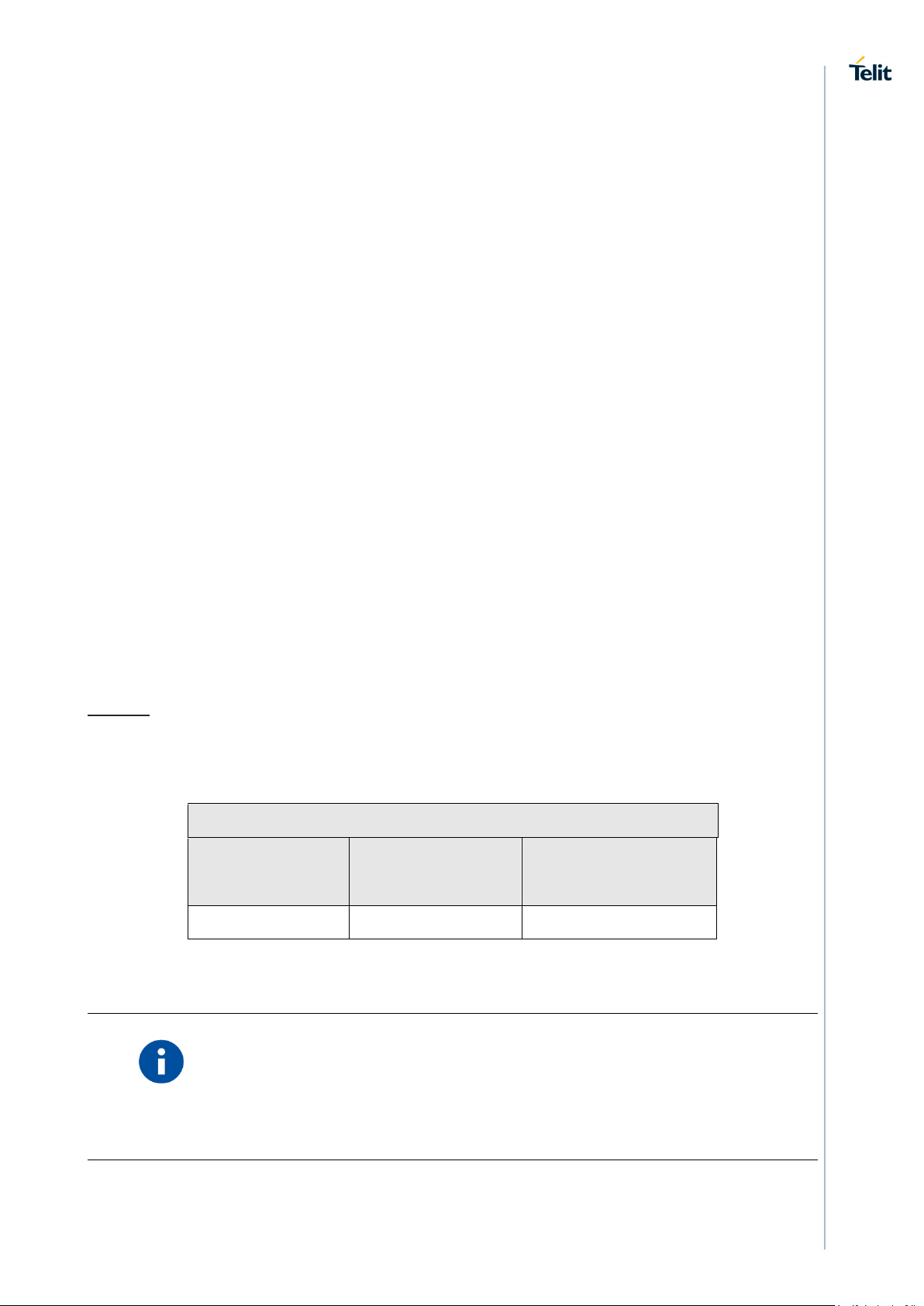
APPLICABILITY TABLE
PRODUCTS
Sw Version Modules
GE310-GNSS 35.00.xx0 2G
GL865-QUAD 34.00.xx0 2G
Note: the features described in the present document are provided by the products equipped
with the software versions equal or higher than the versions shown in the table. See also the
Document History chapter.
1VV0301577 Rev. 2 Page 4 of 28 2020-08-25
Page 5
CONTENTS
NOTICES LIST ................................................................................................... 2
COPYRIGHTS .................................................................................................... 2
COMPUTER SOFTWARE COPYRIGHTS ........................................................ 2
USAGE AND DISCLOSURE RESTRICTIONS ................................................. 3
I. License Agreements ........................................................................ 3
II. Copyrighted Materials ...................................................................... 3
III. High Risk Materials .......................................................................... 3
IV. Trademarks ...................................................................................... 3
V. Third Party Rights ............................................................................ 3
APPLICABILITY TABLE .................................................................................... 4
CONTENTS ........................................................................................................ 5
1. INTRODUCTION .............................................................................. 6
Scope ............................................................................................... 6
Audience........................................................................................... 6
Contact Info and Support ................................................................. 6
Text Conventions ............................................................................. 7
Related Documents .......................................................................... 8
Abbreviation and Acronyms ............................................................. 8
2. OVERVIEW ...................................................................................... 9
3. SERIAL MULTIPLEXER PROTOCOL .......................................... 12
CMUX Frames Structures .............................................................. 12
3.1.1. UIH Control Channel Frame Coding .............................................. 17
3.1.2. UIH Data Channel Frame Coding .................................................. 20
4. HOW TO DEVELOP A MUX USER APPLICATION .................... 21
5. SUMMARY AND RECOMMENDATIONS ..................................... 24
6. TELIT SERIAL PORT MUX TOOL ................................................ 25
Graphical Interface ......................................................................... 25
7. DOCUMENT HISTORY ................................................................. 27
1VV0301577 Rev. 2 Page 5 of 28 2020-08-25
Page 6

1. INTRODUCTION
Scope
This document covers the more significant standard and proprietary AT commands provided by
Telit's modules. Several module features are described and for each one of them the related AT
commands are explained through examples. This document is not an exhaustive description of
the AT commands implemented on the Telit's modules series, its target is only to give you an entry
point to the AT commands world.
Audience
The present User Guide is addressed to users that need to learn and use quickly standard and
proprietary AT commands. The reader can learn the use of the AT commands through simple
examples shown in the document, and then deepen the interested AT commands reading the
documents [1]/[17] in accordance with the used module.
Contact Info and Support
For general contact, technical support services, technical questions and report documentation
errors contact Telit Technical Support at:
• TS-EMEA@telit.com
• TS-AMERICAS@telit.com
• TS-APAC@telit.com
• TS-SRD@telit.com (for Short Range Devices)
Alternatively, use:
http://www.telit.com/support
For detailed information about where you can buy the Telit modules or for recommendations on
accessories and components visit:
http://www.telit.com
Our aim is to make this guide as helpful as possible. Keep us informed of your comments and
suggestions for improvements.
Telit appreciates feedback from the users of our information.
1VV0301577 Rev. 2 Page 6 of 28 2020-08-25
Page 7
Text Conventions
Danger – This information MUST be followed or catastrophic equipment failure or
bodily injury may occur.
Caution or Warning – Alerts the user to important points about integrating the
module, if these points are not followed, the module and end user equipment may
fail or malfunction.
Tip or Information – Provides advice and suggestions that may be useful when
integrating the module.
All dates are in ISO 8601 format, i.e. YYYY-MM-DD.
1VV0301577 Rev. 2 Page 7 of 28 2020-08-25
Page 8

Related Documents
[1] 3GPP TS 07.10 Version 7.1.0
[2] GE310 AT Commands Reference Guide, code: 80598ST10945A
[3] GE310 Software User Guide, code: 1VV0301566
Abbreviation and Acronyms
DCE Data Communication Equipment
DTE Data Terminal Equipment
MUX Multiplexer
NVM Non Volatile Memory
OS Operating System
TT Trace Tool (Generic Trace Tool)
VSD Virtual Service Device
1VV0301577 Rev. 2 Page 8 of 28 2020-08-25
Page 9
VSD Access Points
AT0
AT1
AT2
ASC0/VC1
ASC0/VC2
ASC0/VC3
2. OVERVIEW
Before dealing with the technical characteristics of the CMUX Standard Protocol [1] provided by
the GE310-GNSS Module and the setting up and use of the Telit Serial Port MUX tool running
on DTE (PC-Windows), it is useful to show how the two software components can be used
together and which advantages they give. The GE310 shows three virtual connections (VC1,
VC2, VC3) which are running on a unique physical serial line (COM1/ASC0); the Module has
entered the Multiplexed Mode.
The three different Applications running on DTE are tied, via the virtual connections, to three
Access Points in order to communicate with three different Services provided by the Telit
Module.
The main steps to enter the Multiplexed mode are:
• Telit Module and DTE are physical connected via ASC0/COM1 serial ports, and both are
powered on;
• Run the Telit Serial Port MUX tool on DTE, refer to chapter 6;
• On DTE start, for example, three Hyper Terminals connected to three virtual ports
provided by the Telit tool, e.g. COM3, COM4, COM5.
• Now the Hyper Terminals can send and receive data from the Module on three
independent Virtual Channels by means of the Multiplexer Protocol implemented by the
Telit Tool.
Tab 1 summarizes the VSD Configuration of GE310
Legend:
“ASC0/VCx”: Virtual Connection (channels) that must be used to reach the Access Point
indicated on the top of the column. The user can use one or more Access Points.
Instance #1
Instance #2
Instance #3
Tab 1: CMUX vs. Access Points
NOTE
with the term “instance” is intended an AT Commands Parser. TELIT
modules provide three logically independent AT Commands Parsers. Any
instance is connected to an Access Point. In general, the Access Point is
the connection between the communication path and the Service offered
by the module.
1VV0301577 Rev. 2 Page 9 of 28 2020-08-25
Page 10

Due to the multiplexing feature, operations such as controlling the module or using the SMS
service can be performed via vacant virtual channels without disturbing the existing data flow
and no access to a second Serial Port is needed.
1VV0301577 Rev. 2 Page 10 of 28 2020-08-25
Page 11

Telit CMUX implementation has the following characteristics:
• Operating Option: Basic, refer to [1];
• DLC parameter negotiation (PN) is supported; ref to [1]
• Only UIH frames are supported, refer to [1];
• Three full DLCI (three Virtual Ports);
• Flow control supported only using MSC, FCon and FCoff frames are not supported
1VV0301577 Rev. 2 Page 11 of 28 2020-08-25
Page 12

Control
Length
Indicator
Unspecified length but integral number of
octets
0 1 2 3 4 5 6
7
EA
C/R
DLCI
Session
Direction
Responder
C/R Value
Command/Response
Application
Module
1
Command
Application
Module
1
Response
Application
Module
0
Command
Application
Module
0
Response
3. SERIAL MULTIPLEXER PROTOCOL
The next chapter introduces the CMUX Protocol and its Frames Structures with a particular
attention to the GE310 CMUX implementation. Refer to [1] to have the complete description.
CMUX Frames Structures
All information transmitted between the module and the application is based on frames that have
the following structure:
Flag Address
1 octet 1 octet 1 octet 1or2 octets
Information Field FCS Flag
1 octet 1 octet
Flag Octet
Each frame begins and ends with a flag octet defined as 11111001 in Binary format (0xF9 in
Hexadecimal format).
Address Octet
The form of address octet is the following:
EA: Extension Bit
It is set to 1.
C/R: Command/Response
The Initiator is the entity that sends the first SABM command using DLCI 0. In the Telit CMUX
implementation, the Initiator is always the Application, consequently it sends a command to the
Module with C/R = 1; when the Module (Responder) answers C/R is still 1. If on the same Data
Link session the Module sends a command towards the Application C/R is 0; when the Application
answers C/R is still 0. The table below summarizes the concept.
Initiator
1VV0301577 Rev. 2 Page 12 of 28 2020-08-25
Page 13

DLCI
Virtual Port type
0
Reserved to Control Channel
1
Virtual Port #1
2
Virtual Port #2
3
Virtual Port #3
Frame Type
Control Octet
0 1 2 3 4 5 6 7 SABM (Set Asynchronous Balanced Mode)
1 1 1 1 P/F 1 0 0 UA (Unnumbered Acknowledgement)
1 1 0 0 P/F 1 1 0 DM (Disconnected Mode)
1 1 1 1 P/F 0 0 0 DISC (Disconnect)
1 1 0 0 P/F 0 1 0 UIH (Unnumbered Information with Header check)
1 1 1 1 P/F 1 1
1
DLCI: Data Link Connection Identifier
DLCI value identifies the Virtual Port inside the Module with the following assignment:
Control Octet
The content of the control octet defines the type of frame as in the following table:
P/F stands for Poll/Final bit:
Refer to [1] to have a detailed description.
SABM (Set Asynchronous Balanced Mode)
The SABM command is used by the application to start the HDLC Connection and module will
answer to this command with an UA Frame.
UA (Unnumbered Acknowledgement)
The UA response is sent by the module as an acknowledgement that a SABM or DISC command
was accepted.
DM (Disconnected Mode)
1VV0301577 Rev. 2 Page 13 of 28 2020-08-25
Page 14

In case module rejects SABM or DISC command it will send DM response, this happens if for
example a SABM is sent for a DLCI not supported. Or if a DISC is sent to a DLCI Address already
closed.
DISC (Disconnect)
The DISC is used to close a previously established connection. If the application sends a disc for
the DLCI 0 (the control channel), all the established channels will be closed. The module will
answer to this command with an UA Frame.
UIH (Unnumbered Information)
Please refer to the following chapters for the detailed information about UIH
Length Indicator
This Octet specifies the length of the Information Field
0 1 2 3 4 5 6 7
E/A L1 L2 L3 L4 L5 L6 L7
E/A Bit should be 1 in case 7 bits are enough for the length (length <= 127) otherwise length
should be coded with two octets as described below:
Octet 1:
0 1 2 3 4 5 6 7
0 L1 L2 L3 L4 L5 L6 L7
Octet 2:
0 1 2 3 4 5 6 7
L8 L9 L10 L11 L12 L13 L14 L15
1VV0301577 Rev. 2 Page 14 of 28 2020-08-25
Page 15

Bit 1 2 3 4 5 6 7 8 EA
C/R 0 0 0 0 0 1
Value
Octet
Bit 1
Bit 2
Bit 3
Bit 4
Bit 5
Bit 6
Bit 7
Bit 8
1
D1
D2
D3
D4
D5
D6 0 0 2 I1
I2
I3
I4
CL1
CL2
CL3
CL4 3 P1
P2
P3
P4
P5
P6 0 0 4 T1
T2
T3
T4
T5
T6
T7
T8 5 N1
N2
N3
N4
N5
N6
N7
N8 6 N9
N10
N11
N12
N13
N14
N15
N16
7
NA1
NA2
NA3
NA4
NA5
NA6
NA7
NA8
8
K1
K2
K3 0 0 0 0
0
Meaning
I1
I2
I3
I4
Use UIH
frames
0 0 0
0
Use UI frames
1 0 0
0
Use I frames
0 1 0
0
Information Field
The information field is the payload of the frame and carries the user data. The field exists only for
frame type that contains UIH Control Field. The P/F bit should be set to value 0 when this field is
sent.
FCS (Frame Checking Sequence)
Refer to [1] to have a detailed description.
DLC parameter negotiation (PN)
Before a data DLC is set up, the TE and MS must agree on the parameters to be used for that
DLC. These parameters are determined by parameter negotiation.
Be aware that the control channel DLCI 0 doesn’t need the PN frame.
The parameter negotiation uses the following type field octet:
The length field octet contains the value 8 and there follow eight value octets.
The value octets contain are describe in the following table:
The various fields are coded as follows:
• The D-bits define the DLCI that the other information refers to; Bit D1 is the least
significant.
1VV0301577 Rev. 2 Page 15 of 28 2020-08-25
• The I-bits define the type of frames used for carrying information in the particular DLC as
in below table:
Page 16

Meaning
CL1
CL2
CL3
CL4
Type 1
0 0 0
0
Type 2
1 0 0
0
Type 3
0 1 0
0
Type 4
1 1 0
0
NOTE: Other values are reserved. The only supported value in GE310 is 0000.
In the absence of negotiation the frame type used (for DLCI>0) is the same as used by the
multiplexer control channel.
• The CL-bits define the type of convergence layer to be used on the particular DLCI - see
next Table:
Other values are reserved.
• The P-bits define the priority to be assigned to the particular DLC. The range of values is
0 to 63 with 0 being the lowest priority. P1 is the least significant bit. Default value for Pbits are given by the DLCI values.
• The T-bits define the value of the acknowledgement timer (T1). The units are hundredths
of a second and T1 is the least significant bit.
• The N-bits define the maximum frame size (N1). The parameter is a sixteen-bit number
with N1 as the least significant bit.
• The NA-bits define the maximum number of retransmissions (N2). The parameter is an
eight-bit number with NA1 as the least significant bit.
• The K-bits define the window size for error recovery mode (k). The parameter is a four
-bit number with K1 as the least significant bit.
The TE transmits a parameter negotiation command to the MS with the fields set to the values
that the TE intends to use for the particular DLCI. The MS replies with a parameter negotiation
response with its proposed set of values. The following rules must be observed by the MS in
constructing its response:
- The DLCI value may not be changed.
- The use of I frames or UI frames is optional so an MS may respond with a UIH choice if it
does not implement UI frames or I frames.
- The MS may not change the convergence layer proposed by the TE.
- The MS may not change the priority proposed by the TE.
- The T1 value is the one that the TE will use and is not negotiable; the MS will insert its own
T1 value. It is advisable that different T1s are used in each direction.
- The MS may propose a smaller value for maximum frame size (N1) if it has insufficient
memory to handle the size proposed.
- The N2 value is the one that the TE will use and is not negotiable; the MS will insert its
own N2 value.
- The MS may propose a smaller value for window size (k) if it has insufficient memory to
handle the size proposed.
If the TE considers the response from the MS to be acceptable the TE will start to establish the
DLC in accordance with the procedures 3GPP. If the response is not acceptable the TE may
1VV0301577 Rev. 2 Page 16 of 28 2020-08-25
Page 17

LSb
MSb
LSb
MSb
initiate another parameter negotiation command with revised parameters or pass the failure
information to a higher layer.
If an incoming call arrives at the MS from the network for which no DLC has been set up, the MS
may initiate the parameter negotiation procedure and set up a DLC. This situation should not
occur in practice since a TE will generally set up DLCs for all the functions it shares with the MS
after the capabilities exchange. The indication of an incoming call will be through an 07.07 or
07.05 result code.
3.1.1. UIH Control Channel Frame Coding
Refer to [1] and the figure below: the Information field can carry UIH Commands or User Data.
The Information field exists only for UIH frame type. The P/F bit should be set to value 0 when
this field is sent. This chapter focuses on the UIH Commands; in this case DLCI shall always
have the value 0. It means that the UIH Command is transferred on the logical Control Channel
Flag Address Control Length Indicator
1 octet 1 octet 1 octet 1or2 octets Unspecified length but integral number of octets 1 octet 1 octet
Information Field FCS Flag
TYPE Length Indicator Value
EA C/R TYPE 1 or 2 octets N octets
0 1 2 3 4 5 6 7
EA C/R TYPE
Type Octet:
EA: Extension Bit
It is always set to 1.
C/R: Identifies if it is a Command or Response
TYPE: Hereafter are listed the UIH Commands TYPES followed by their Length Indicators (for its
coding see chapter 3.1).
If Length Indicators is not zero, it is followed the Values octets.
Multiplexer close down (CLD)
The CLD command is used to reset the link, exit Multiplexed Mode and enter AT Command Mode.
Type Length Indicator
E/A C/R 0 0 0 0 1 1 E/A 0 0 0 0 0 0 0
1VV0301577 Rev. 2 Page 17 of 28 2020-08-25
Page 18

LSb
MSb
LSb
MSb
Test Command (Test)
Feature NOT Supported
Modem Status Command (MSC)
MSC command is used to send Virtual V.24 Signals status. Each Virtual Connection has its own
independent Virtual V.24 Signals status.
Format without Break Indication:
Type Length Indicator DLCI V24 octet
E/A C/R 0 0 0 1 1 1 E/A 0 1 0 0 0 0 0 E/A 1 DLCI E/A Lines Status
Format with Break Indication:
Type Length Indicator DLCI V24 octet Break octet
E/A C/R 0 0 0 1 1 1 E/A 1 1 0 0 0 0 0 E/A 1 DLCI E/A Lines
Status
V.24 Octet from Module to Application
0 1 2 3 4 5 6 7
1 FC DSR CTS 0 0 RING DCD
Fig. 1: V.24 Octet DCE DTE
V.24 Octet from Application to Module
Break
Status
0 1 2 3 4 5 6 7
1 FC DTR RTS 0 0 0 0
Fig. 2: V.24 Octet DTE DCE
FC: this bit is set to 1 when module or application is not able to accept any frames.
CTS: this bit is set to 1 when module is able to receive data (ref. cmd &K,\Q and related)
RTS: this bit is set to 1 when application is able to receive data. (ref. cmd &K,\Q and related)
DSR: this bit is set to 1 when module is ready to communicate (ref. cmd &S, and related)
1VV0301577 Rev. 2 Page 18 of 28 2020-08-25
Page 19

LSb
MSb
DTR: this bit is set to 1 when application is ready to receive data. (ref. cmd &D, and related)
RING: this bit is set to 1 when module receive an incoming call (ref. cmd \R, and related)
DCD: this bit is set to 1 when module has an active data connection. (ref. cmd &C, and related)
NOTICE:
when a new instance is established the default settings are FC = 1, RTS =
0, DTR = 0, this means that the module will not be able to send the data to
application until user changes the default setting to FC = 0, RTS = 1, DTR
= 1. The application will send an MSC command to change this value before
starting sending data.
Break Octet
0 1 2 3 4 5 6 7
1 0 0 0 0 0 0 0
This octet will be sent each time a Break Signal is simulated.
Not Supported Command Response (NSC)
This response is sent in case a command type is not supported by the receiving entity.
Type Length Indicator Command Type
E/A C/R 0 0 1 0 0 0 E/A 1 0 0 0 0 0 0 E/A C/R command type
1VV0301577 Rev. 2 Page 19 of 28 2020-08-25
Page 20

LSb
MSb
LSb
MSb
Power Saving Control (PSC)
Standard PSC command is used to cause the Telit Module to enter the Power Saving Mode when
it is in Multiplexed Mode. It simulates the N=0 command.
Type Length Indicator
E/A C/R 0 0 0 0 1 0 E/A 0 0 0 0 0 0 0
PSC command has one more octet containing the Power Saving Mode
Type Length Indicator Power Saving Mode
E/A C/R 0 0 0 0 1 0 E/A 1 0 0 0 0 0 0 mode
3.1.2. UIH Data Channel Frame Coding
Refer to [1] and the figure: the Information field is the payload of the frame and carries the user
data. The Information field exists only for UIH frame type. The P/F bit should be set to value 0
when this field is sent.
Flag Address Control Length Indicator
1 octet 1 octet 1 octet 1or2 octets Unspecified length but integral number of octets 1 octet 1 octet
Information Field FCS Flag
User data
N octets
Length indicator
It specifies the length of the Information field. See its coding in chapter 3.1
User Data
User payload, the number of octets is defined by the Length Indicator
1VV0301577 Rev. 2 Page 20 of 28 2020-08-25
Page 21

4. HOW TO DEVELOP A MUX USER APPLICATION
Objective of this chapter is to provide the reader with the guidelines to develop a User
Application able to cause the connected module enters Multiplexed Mode and support the
Multiplexing Protocol without the assistance of the Telit Serial Port MUX tool.
1VV0301577 Rev. 2 Page 21 of 28 2020-08-25
Page 22

commands are sent by means of a regular serial line protocol, no
First of all, the User Application must force the connected module in Multiplexed Mode. To do that,
it sends the AT commands listed below
Select the Serial Port Speed.
AT+IPR=115200
OK
Store the setting on profile 0 and at power on use profile 0
AT&W0&P0
OK
Start MUX protocol (Module enters Multiplexed Mode):
AT+CMUX=0
When the User Application receives the OK response of the +CMUX command, the module
entered the Multiplexed Mode and the regular serial line protocol is no more available. The User
Application can continue to be connected with the module only via the Multiplexing Protocol, see
the example of CMUX messages sequence in hexadecimal format listed on the next page.
NOTE:
the
Multiplexing Protocol is still activated during this phase..
After entering +CMUX AT Command, the CMUX protocol substitutes the regular serial line
protocol. Hereafter is listed an example of CMUX protocol.
The messages are in hexadecimal format.
Legend:
Red - messages sent from User Application (DTE) to Module (DCE)
Green - messages sent from Module to User Application
Black - comments
DLC establishment on Control Channel:
F9 03 3F 01 1C F9 -DLCI = 0, SABM CMD, POLL BIT=1
F9 03 73 01 D7 F9 -DLCI = 0, UA RESPONSE, FINAL BIT=1
1VV0301577 Rev. 2 Page 22 of 28 2020-08-25
Page 23

DLC establishment on Virtual Channel # 1 (Open Virtual Port #1):
F9 03 EF 15 83 11 01 00 07 0A 7A 00 03 02 EE F9 PN CMD for DLCI 1
F9 01 EF 15 81 11 01 00 07 0A 7A 00 03 02 8F F9 PN RESPONSE for DLCI 1
F9 07 3F 01 DE F9 -DLCI = 1, SABM CMD, POLL BIT=1
F9 07 73 01 15 F9 -DLCI = 1, UA RESPONSE, FINAL BIT=1
.
.
.
DLC establishment on Virtual Channel # 2 (Open Virtual Port #2)
.
F9 03 EF 15 83 11 02 00 07 0A 7A 00 03 02 EE F9 PN CMD for DLCI 2
.
F9 0B 3F 01 59 F9 -DLCI = 2, SABM CMD, POLL BIT=1
.
.
User Application sends the AT Command: AT+CGMR<CR>
F9 07 EF 11 41 54 2B 43 47 4D 52 0D 2B F9
Module answers the AT command result: <CR><LF> 35.00.000B004<CR><LF><CR><LF><OK><CR><LF>
F9 05 EF 25 0D 0A 33 35 2E 30 30 2E 30 30 30 2D 42 30 30 34 0D 0A 69 F9 F9 05 EF 0D 0D
0A 4F 4B 0D 0A 5F F9User Application causes the module to enter Power Saving Mode.
UIH Frame, PSC CMD
F9 03 EF 05 41 01 F2 F9
1VV0301577 Rev. 2 Page 23 of 28 2020-08-25
Page 24

5. SUMMARY AND RECOMMENDATIONS
The customer/integrator to design its own Multiplexer Protocol Application shall remember:
• Telit Module supports the CMUX Basic Option and UIH Frames according to [1];
• Serial Port must be so configured: 8 data bits, no parity, 1 stop bit;
If the Telit Module is operating in Multiplexer Mode, the following restrictions will be applied:
• Software Flow control XON/XOFF is not supported;
• Call control: a voice call can be initiated, answered and closed on any channel;
• Call control: Data or Fax call can be initiated and answered on any channel but closed
only on the channel where the call was started/answered;
• Phonebook access: if you wish to write the same phonebook entry using two or more
different Virtual Channels at the same time, please note that only the last entry will be
stored;
1VV0301577 Rev. 2 Page 24 of 28 2020-08-25
Page 25

6. TELIT SERIAL PORT MUX TOOL
Telit has developed a tool called Telit Serial Port MUX;
the tool is running on a PC-Windows. From the figures it is possible infer that three Virtual
Channels can exist at the same time on one physical line (COM1). Three logical COMx,
provided by the Windows OS, can be used by three different PC-Applications to gain one of the
three Virtual Channels.
With the GE310 it is required to use at least the version 3.0.9_TDK_2.0.75
Graphical Interface
After installing Telit Serial Port Mux tool on PC-Windows, it looks as in the following figure:
Select Setup Menu to configure the Main
Port and the Virtual Ports. The Configure
Panel is self- explanatory.
1VV0301577 Rev. 2 Page 25 of 28 2020-08-25
Page 26

Click Modem Type
Menu to select the
Telit Modem in
accordance with the
actual Telit Modem
connected to the
DTE.
Click Frame Size
Menu to define the
Maximum Frame
Structure Length
Before interfacing the module and after the first installation of this tool it is necessary to edit the
TSPMux.ini file present in C:\PFiles\Telit\TelitSerialPortMux setting the below section highlighted
in Yellow as in the example:
[ChannelPh]
ChnlType=RS232
ChnlPort=COM25
ChnlSpeed=115200
CmuxDsrSensitivity=0
CmuxIgnoreDtr=1
1VV0301577 Rev. 2 Page 26 of 28 2020-08-25
Page 27

7. DOCUMENT HISTORY
Revision Date Products/SW Versions Changes
0 2019-01-10 35.00.xx0 -
1 2019-01-16 35.00.xx0
2 2019-01-16 35.00.xx0/35.00.xx0 Add GL865-QUAD V4 product
Corrected missing links in the
text.
1VV0301577 Rev. 2 Page 27 of 28 2020-08-25
Page 28

 Loading...