

Page 1
Mod. 0805 2017-01 Rev.6
CHARLIE EVK
HW User Guide
1VV0301670 Rev. 5 – 2021-02-02
Page 2

CHARLIE HW User Guide
1VV0301670 Rev. 5 Page 2 of 38 2021-02-02
SPECIFICATIONS ARE SUBJECT TO CHANGE WITHOUT NOTICE
NOTICE
While reasonable efforts have been made to assure the accuracy of this document, Telit
assumes no liability resulting from any inaccuracies or omissions in this document, or from
use of the information obtained herein. The information in this document has been carefully
checked and is believed to be reliable. However, no responsibility is assumed for
inaccuracies or omissions. Telit reserves the right to make changes to any products
described herein and reserves the right to revise this document and to make changes from
time to time in content hereof with no obligation to notify any person of revisions or changes.
Telit does not assume any liability arising out of the application or use of any product,
software, or circuit described herein; neither does it convey license under its patent rights
or the rights of others.
It is possible that this publication may contain references to, or information about Telit
products (machines and programs), programming, or services that are not announced in
your country. Such references or information must not be construed to mean that Telit
intends to announce such Telit products, programming, or services in your country.
COPYRIGHTS
This instruction manual and the Telit products described in this instruction manual may be,
include or describe copyrighted Telit material, such as computer programs stored in
semiconductor memories or other media. Laws in the Italy and other countries preserve for
Telit and its licensors certain exclusive rights for copyrighted material, including the
exclusive right to copy, reproduce in any form, distribute and make derivative works of the
copyrighted material. Accordingly, any copyrighted material of Telit and its licensors
contained herein or in the Telit products described in this instruction manual may not be
copied, reproduced, distributed, merged or modified in any manner without the express
written permission of Telit. Furthermore, the purchase of Telit products shall not be deemed
to grant either directly or by implication, estoppel, or otherwise, any license under the
copyrights, patents or patent applications of Telit, as arises by operation of law in the sale
of a product.
COMPUTER SOFTWARE COPYRIGHTS
The Telit and 3rd Party supplied Software (SW) products described in this instruction
manual may include copyrighted Telit and other 3rd Party supplied computer programs
stored in semiconductor memories or other media. Laws in the Italy and other countries
preserve for Telit and other 3rd Party supplied SW certain exclusive rights for copyrighted
computer programs, including the exclusive right to copy or reproduce in any form the
copyrighted computer program. Accordingly, any copyrighted Telit or other 3rd Party
supplied SW computer programs contained in the Telit products described in this instruction
manual may not be copied (reverse engineered) or reproduced in any manner without the
express written permission of Telit or the 3rd Party SW supplier. Furthermore, the purchase
of Telit products shall not be deemed to grant either directly or by implication, estoppel, or
otherwise, any license under the copyrights, patents or patent applications of Telit or other
3rd Party supplied SW, except for the normal non-exclusive, royalty free license to use that
arises by operation of law in the sale of a product.
Page 3

CHARLIE HW User Guide
1VV0301670 Rev. 5 Page 3 of 38 2021-02-02
USAGE AND DISCLOSURE RESTRICTIONS
I. License Agreements
The software described in this document is the property of Telit and its licensors. It is
furnished by express license agreement only and may be used only in accordance with the
terms of such an agreement.
II. Copyrighted Materials
Software and documentation are copyrighted materials. Making unauthorized copies is
prohibited by law. No part of the software or documentation may be reproduced,
transmitted, transcribed, stored in a retrieval system, or translated into any language or
computer language, in any form or by any means, without prior written permission of Telit
III. High Risk Materials
Components, units, or third-party products used in the product described herein are NOT
fault-tolerant and are NOT designed, manufactured, or intended for use as on-line control
equipment in the following hazardous environments requiring fail-safe controls: the
operation of Nuclear Facilities, Aircraft Navigation or Aircraft Communication Systems, Air
Traffic Control, Life Support, or Weapons Systems (High Risk Activities"). Telit and its
supplier(s) specifically disclaim any expressed or implied warranty of fitness for such High
Risk Activities.
IV. Trademarks
TELIT and the Stylized T Logo are registered in Trademark Office. All other product or
service names are the property of their respective owners.
V. Third Party Rights
The software may include Third Party Right software. In this case you agree to comply with
all terms and conditions imposed on you in respect of such separate software. In addition
to Third Party Terms, the disclaimer of warranty and limitation of liability provisions in this
License shall apply to the Third Party Right software.
TELIT HEREBY DISCLAIMS ANY AND ALL WARRANTIES EXPRESS OR IMPLIED
FROM ANY THIRD PARTIES REGARDING ANY SEPARATE FILES, ANY THIRD PARTY
MATERIALS INCLUDED IN THE SOFTWARE, ANY THIRD PARTY MATERIALS FROM
WHICH THE SOFTWARE IS DERIVED (COLLECTIVELY “OTHER CODE”), AND THE
USE OF ANY OR ALL THE OTHER CODE IN CONNECTION WITH THE SOFTWARE,
INCLUDING (WITHOUT LIMITATION) ANY WARRANTIES OF SATISFACTORY
QUALITY OR FITNESS FOR A PARTICULAR PURPOSE.
NO THIRD PARTY LICENSORS OF OTHER CODE SHALL HAVE ANY LIABILITY FOR
ANY DIRECT, INDIRECT, INCIDENTAL, SPECIAL, EXEMPLARY, OR CONSEQUENTIAL
DAMAGES (INCLUDING WITHOUT LIMITATION LOST PROFITS), HOWEVER CAUSED
AND WHETHER MADE UNDER CONTRACT, TORT OR OTHER LEGAL THEORY,
ARISING IN ANY WAY OUT OF THE USE OR DISTRIBUTION OF THE OTHER CODE
OR THE EXERCISE OF ANY RIGHTS GRANTED UNDER EITHER OR BOTH THIS
LICENSE AND THE LEGAL TERMS APPLICABLE TO ANY SEPARATE FILES, EVEN IF
ADVISED OF THE POSSIBILITY OF SUCH DAMAGES.
Page 4

CHARLIE HW User Guide
1VV0301670 Rev. 5 Page 4 of 38 2021-02-02
APPLICABILITY TABLE
PRODUCTS
CHARLIE EVALUATION KIT
Page 5

CHARLIE HW User Guide
1VV0301670 Rev. 5 Page 5 of 38 2021-02-02
Contents
NOTICE 2
COPYRIGHTS .................................................................................................. 2
COMPUTER SOFTWARE COPYRIGHTS ....................................................... 2
USAGE AND DISCLOSURE RESTRICTIONS ................................................ 3
I. License Agreements ....................................................................... 3
II. Copyrighted Materials .................................................................... 3
III. High Risk Materials ........................................................................ 3
IV. Trademarks .................................................................................... 3
V. Third Party Rights ........................................................................... 3
APPLICABILITY TABLE .................................................................................. 4
CONTENTS ...................................................................................................... 5
1. INTRODUCTION ............................................................................ 7
1.1. Scope ............................................................................................. 7
1.2. Audience ........................................................................................ 7
1.3. Contact Information, Support ......................................................... 7
1.4. Text Conventions ........................................................................... 9
1.5. Related Documents ...................................................................... 10
2. OVERVIEW .................................................................................. 11
NOTICE 13
3. CONNECTORS ............................................................................ 14
3.1. Arduino MKR format Pin-out ........................................................ 14
3.2. MCU Native USB Connector ........................................................ 16
3.3. ME310 Native USB Connector ..................................................... 17
3.4. MCU DEBUG connector ............................................................... 18
3.5. SIM Connectors ............................................................................ 19
3.6. ANTENNA Connectors ................................................................. 20
4. CIRCUIT BLOCKS ....................................................................... 21
4.1. MCU to ME310 serial connection ................................................. 21
4.2. BMA400 Accelerometer ............................................................... 22
4.3. MCU Buttons and LEDs ............................................................... 23
4.4. ME310 SLED ................................................................................ 24
Page 6

CHARLIE HW User Guide
1VV0301670 Rev. 5 Page 6 of 38 2021-02-02
4.5. MCU Reset Button ....................................................................... 25
4.6. Battery Charger ............................................................................ 26
4.7. 3V3 Power Supply ........................................................................ 29
4.8. 1V8 Power Supply ........................................................................ 30
4.9. 3V8 Power Supply ........................................................................ 31
4.10. ME310 ON/OFF Switch ................................................................ 32
4.11. MCU RTC Clock ........................................................................... 32
5. MECHANICAL DESIGN............................................................... 33
5.1. Drawing ........................................................................................ 33
6. SAFETY RECOMMENDATIONS ................................................. 34
6.1. READ CAREFULLY ..................................................................... 34
7. ACRONYMS ................................................................................ 35
8. DOCUMENT HISTORY ................................................................ 37
Page 7

CHARLIE HW User Guide
1VV0301670 Rev. 5 Page 7 of 38 2021-02-02
1. INTRODUCTION
1.1. Scope
Scope of this document is to describe the hardware components of the CHARLIE EVK
board based on Telit ME310G1-WW module and ATSAMD21G18 MCU from Microchip.
1.2. Audience
This document is intended for Telit customers, who are integrators, about to implement their
applications using our CHARLIE EVK board.
Design of the Charlie Evaluation Kit is heavily optimized for small size,
it is not a reference design for generic use.
Before copying it “as is”, please contact Telit Application Engineering
for a design review and suggestions to optimize it according to your
design constraints.
1.3. Contact Information, Support
For general contact, technical support services, technical questions and report
documentation errors contact Telit Technical Support at:
• TS-EMEA@telit.com
• TS-AMERICAS@telit.com
• TS-APAC@telit.com
• TS-SRD@telit.com
Alternatively, use:
http://www.telit.com/support
For detailed information about where you can buy the Telit modules or for recommendations
on accessories and components visit:
http://www.telit.com
Our aim is to make this guide as helpful as possible. Keep us informed of your comments
and suggestions for improvements.
Telit appreciates feedback from the users of our information.
Page 8

CHARLIE HW User Guide
1VV0301670 Rev. 5 Page 8 of 38 2021-02-02
Page 9
CHARLIE HW User Guide
1VV0301670 Rev. 5 Page 9 of 38 2021-02-02
1.4. Text Conventions
Danger – This information MUST be followed or catastrophic
equipment failure or bodily injury may occur.
Caution or Warning – Alerts the user to important points about
integrating the module, if these points are not followed, the module and
end user equipment may fail or malfunction.
Tip or Information – Provides advice and suggestions that may be
useful when integrating the module.
All dates are in ISO 8601 format, i.e. YYYY-MM-DD.
Page 10

CHARLIE HW User Guide
1VV0301670 Rev. 5 Page 10 of 38 2021-02-02
1.5. Related Documents
• ME310G1 HW User Guide, 1VV0301351
Page 11
CHARLIE HW User Guide
1VV0301670 Rev. 5 Page 11 of 38 2021-02-02
2. OVERVIEW
The aim of this document is to describe the “CHARLIE” EVK board based on Telit
ME310G1-WW modem module and ATSAMD21G18 MCU from Microchip.
The CHARLIE board is an Arduino MKR form factor evaluation board that can be
programmed with Arduino IDE or with native tools for ATSAMD21 from Microchip.
The CHARLIE EVK board is powered either by
• onboard USB connectors
• VIN pin on connector
Using either the onboard 3.8V DC power supply or by a 3.7 V LIPO battery.
All GPIO pins of Telit ME310G1-WW levels are set to 1.8 V, while all GPIO from
ATSAMD21 MCU are set at 3.3 V.
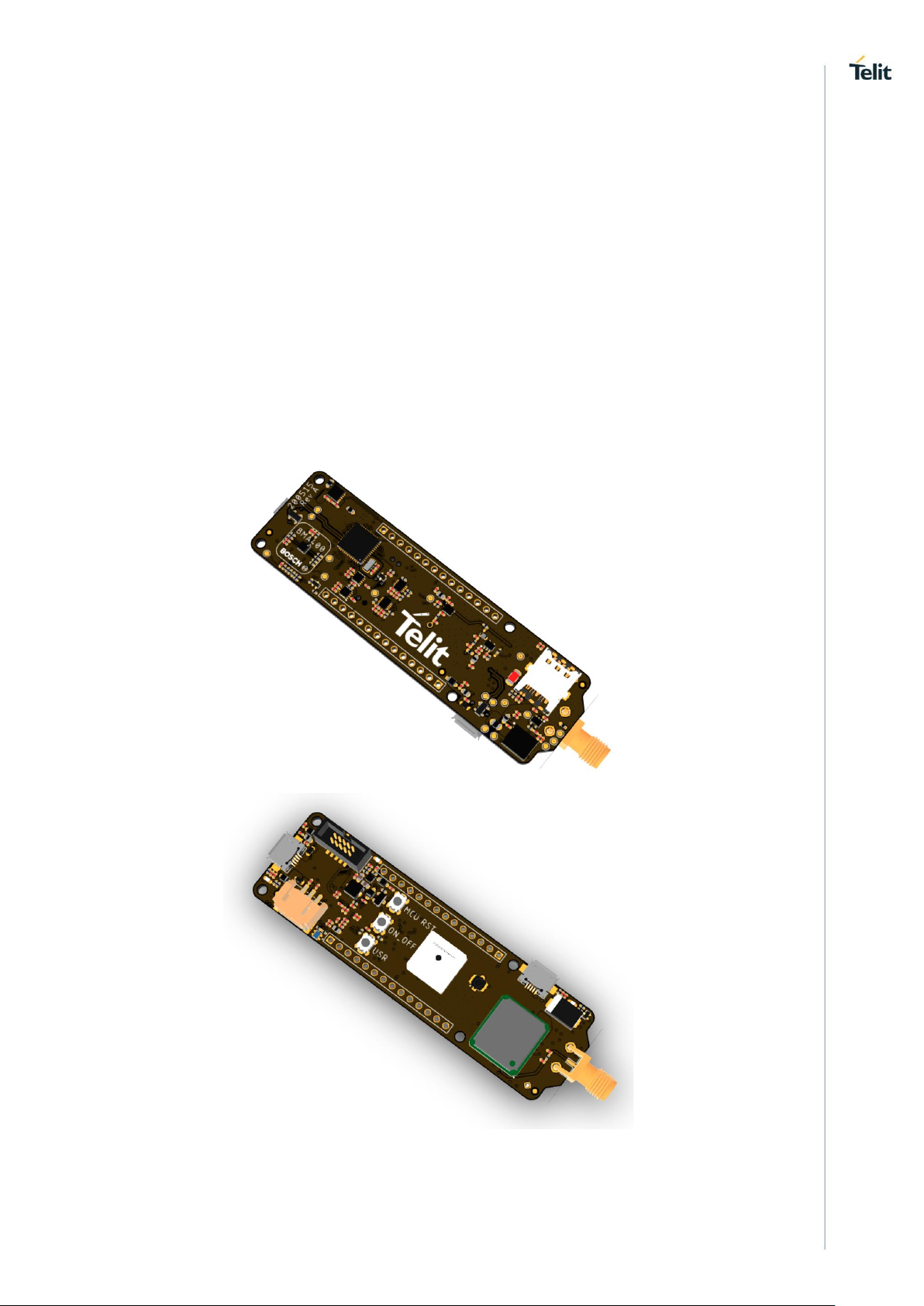
This document lists and describes circuit building blocks and connectors
Figure 1 - CHARLIE EVK Board
Page 12
CHARLIE HW User Guide
1VV0301670 Rev. 5 Page 12 of 38 2021-02-02
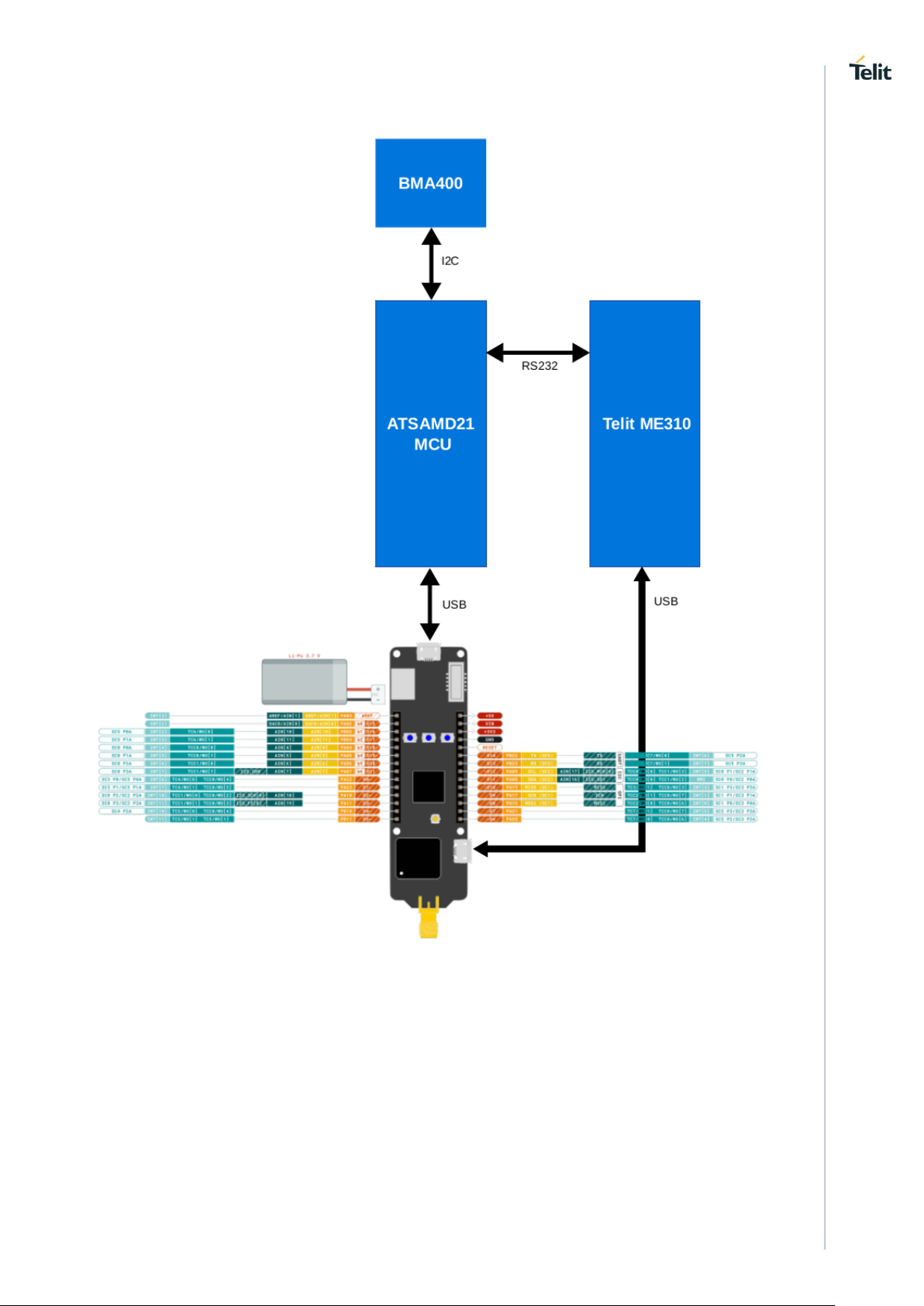
Figure 2 - CHARLIE Block Diagram
The CHARLIE EVK has 2 USB connectors:
• The first USB connector is located at opposite site of ME310 module and SMA
connector is connected to the ATSAMD21 microcontroller
• The second USB connector is located near to the ME310 module and SMA
connector is connected to the ME310 module
ATSAMD21 MCU communicates with Telit ME310 module using an asynchronous serial
connection.
The ATSAMD21 MCU is connected to the onboard BMA400 accelerometer from Bosch
Sensortec.
Page 13

CHARLIE HW User Guide
1VV0301670 Rev. 5 Page 13 of 38 2021-02-02
NOTICE
While reasonable efforts have been made to assure the accuracy of this document, Telit
assumes no liability resulting from any inaccuracies or omissions in this document, or from
use of the information obtained herein. The information presented in this document is
believed to be accurate and reliable. However, no responsibility is assumed by Telit
Communications S.p.A. for its use, nor any infringement of patents or other rights of third
parties which may result from its use. No license is granted by implication or otherwise
under any patent rights of Telit Communications S.p.A. other than for circuitry embodied in
Telit products. This document is subject to change without notice.
Page 14

CHARLIE HW User Guide
1VV0301670 Rev. 5 Page 14 of 38 2021-02-02
3. CONNECTORS
3.1. Arduino MKR format Pin-out
Figure 3 - Arduino MKR Pinout
Pin
Signal
I/O
Function
Type
MCU I/O
POWER SUPPLY
J4,14
+5V
O
5.0 V I/O Level
J4,13
VIN
I
External Power Input
J4,12
+3V3
O
3.3 V I/O Level
J4,11
GND -
GPIO INTERFACE @ 3V3
J4,10
RESET
I
MCU Reset
J4,9
D14
I/O
GPIO/USART TX
PB22
J4,8
D13
I/O
GPIO/USART RX
PB23
J4,7
D12
I/O
GPIO/I2C SCL
PA09
Page 15

CHARLIE HW User Guide
1VV0301670 Rev. 5 Page 15 of 38 2021-02-02
J4,6
D11
I/O
GPIO/I2C SDA
PA08
J4,5
D10
I/O
GPIO/SPI MISO
PA19
J4,4
D9
I/O
GPIO/SPI SCK
PA17
J4,3
D8
I/O
GPIO/SPI MOSI
PA16
J4,2
D7
I/O
GPIO/PWM
PA21
J4,1
D6
I/O
GPIO/PWM
PA20
J3,14
D5
I/O
GPIO/PWM
PB11
J3,13
D4
I/O
GPIO/PWM
PB10
J3,12
D3
I/O
GPIO/PWM
PA11
J3,11
D2
I/O
GPIO/PWM
PA10
J3,10
D1
I/O
GPIO
PA23
J3,9
D0
I/O
GPIO
PA22
J3,8
D21/A6
I/O
GPIO/AIN[7]
PA07
J3,7
D20/A5
I/O
GPIO/AIN[6]
PA06
J3,6
D19/A4
I/O
GPIO/AIN[5]
PA05
J3,5
D18/A3
I/O
GPIO/AIN[4]
PB04
J3,4
D17/A2
I/O
GPIO/AIN[11]
PB03
J3,3
D16/A1
I/O
GPIO/AIN[10]
PB02
J3,2
D15/A0
I/O
GPIO/AIN[0]
PA02
J3,1
AREF
I
AREF/AIN[1]
PA03
Page 16

CHARLIE HW User Guide
1VV0301670 Rev. 5 Page 16 of 38 2021-02-02
3.2. MCU Native USB Connector
Figure 4 – ATSAMD21 Native USB
Pin
Signal
I/O
Function
Type
Comment
POWER SUPPLY
J1,1
5V
I
J1,5
GND
-
USB HS 2.0 COMMUNICATION PORT (FW upgrade and Data)
J1,2
USB_DM
I/O
USB differential Data (-)
PA24
J1,3
USB_DP
I/O
USB differential Data (+)
PA25
J1,4
USB OTG ID
N.C.
The J1 USB plug is connected to the ATSAMD21 MCU native USB port. The board is
protected by resettable fuse and ESD discharge.
Page 17

CHARLIE HW User Guide
1VV0301670 Rev. 5 Page 17 of 38 2021-02-02
3.3. ME310 Native USB Connector
Figure 5 – ME310 Native USB
Pin
Signal
I/O
Function
Type
ME310
POWER SUPPLY
J7,1
5V I USB_VBUS
T18
J7,5
GND
-
USB HS 2.0 COMMUNICATION PORT (FW upgrade and Data)
J7,2
USB_DM
I/O
USB differential Data (-)
V18
J7,3
USB_DP
I/O
USB differential Data (+)
U19
J7,4
USB OTG ID
N.C.
The J7 USB plug is connected to the ME310 native USB port. The board is protected by
resettable fuse and ESD discharge.
Page 18

CHARLIE HW User Guide
1VV0301670 Rev. 5 Page 18 of 38 2021-02-02
3.4. MCU DEBUG connector
Figure 6 - DEBUG connector
Pin
Signal
I/O
Function
Type
Comment
POWER SUPPLY
J2,1
3V3
I
J2,3
GND
-
J2,5
GND
-
J2,9
GND
-
DEBUG Interface
J2,2
SWDIO
I/O
DEBUG DATA
PA31
J2,4
SWCLK I DEBUG CLOCK
PA30
J2,10
RESETN I RESET
RESETN
Page 19

CHARLIE HW User Guide
1VV0301670 Rev. 5 Page 19 of 38 2021-02-02
3.5. SIM Connectors
Figure 7 - SIM Sockets
The board supports a micro SIM socket and includes pads to solder an eSIM: both inputs
are ESD protected.
Page 20

CHARLIE HW User Guide
1VV0301670 Rev. 5 Page 20 of 38 2021-02-02
3.6. ANTENNA Connectors
Figure 8 – Antennas
The 4G Cellular antenna signal is connected to the J8 SMA connector.
The GNSS Signal can be connected either to the uFL connector J9 or
the GPS Patch Antenna, which is enabled by default.
In order to disable the Patch Antenna and connect an external GPS
antenna to J9, remove R48 and R21 resistors and solder a 0-ohm
resistor on R20 pads and a 100 pF capacitor on C89 pads.
Page 21

CHARLIE HW User Guide
1VV0301670 Rev. 5 Page 21 of 38 2021-02-02
4. CIRCUIT BLOCKS
4.1. MCU to ME310 serial connection
Figure 9 –MCU to ME310 Serial Connection
The ATSAMD21 MCU GPIO works at 3.3 V while the ME310 GPIO levels are 1.8 V. To
connect the two devices using a serial connection with hardware handshake, level shifters
are used.
MCU Pin
MCU Direction
Function
ME310 Direction
ME310 Pin
PA15 I CTS
O
AA17
PA13 I RXD
O
AA15
PA14 O RTS
I
Y18
PA12 O TXD
I
Y16
PA28 I RI
O
D13
PA27 O DTR
I
D11
Page 22

CHARLIE HW User Guide
1VV0301670 Rev. 5 Page 22 of 38 2021-02-02
4.2. BMA400 Accelerometer
Figure 10 – BMA400 Accelerometer
The CHARLIE board mounts a Bosch Sensortech BMA400 ultra low power acceleration
sensor, connected to the ATSAMD21 MCU through I2C communication.
Pin
Direction
Function
PA09
O
I2C Clock
PA08
I/O
I2C Data
PB09 I INT1 from BMA400
PA18 I INT2 from BMA400
Page 23

CHARLIE HW User Guide
1VV0301670 Rev. 5 Page 23 of 38 2021-02-02
4.3. MCU Buttons and LEDs
Figure 11 – ATSAMD21 Pushbuttons and Leds
The CHARLIE board has a user-available LED, LD1 and a button, PB2 connected to
ATSAMD21 MCU. The led is ON when the MCU pin is high, while the button is active
LOW.
Pin
Direction
Function
PA20
I
User Button
PA21
O
User RED LED
Page 24

CHARLIE HW User Guide
1VV0301670 Rev. 5 Page 24 of 38 2021-02-02
4.4. ME310 SLED
Figure 12 – ME310 SLed
The CHARLIE board has a LED, LD2 connected to ME310 S_LED pin. The led is ON
when the MCU pin is high.
Pin
Direction
Function
B2
O
Amber LD2/S_LED
Page 25

CHARLIE HW User Guide
1VV0301670 Rev. 5 Page 25 of 38 2021-02-02
4.5. MCU Reset Button
Figure 13 – RESET button
The CHARLIE board has one RESET button PB1 connected to ATSAMD21 MCU.
Page 26

CHARLIE HW User Guide
1VV0301670 Rev. 5 Page 26 of 38 2021-02-02
4.6. Battery Charger
Figure 14 - Battery Charger
A +3.7 V Lipo battery (not included) connected to J10 can power the CHARLIE board.
The battery can be charged by the onboard charger, which receives receives +5V from
the VIN connector, MCU USB Native Connector or ME310 Native USB connector.
When an external power source is present and the battery is connected, the battery is
charged. The Board voltage is supplied by the external power source.
When the external power source is disconnected, the CHARLIE board is battery powered
The battery charger notifies its status through the 3 LEDs:
Pin
Direction
LED
Function
PG
O
LD3 green
Power Good
STAT1
O
LD4A yellow
Charging
STAT2
O
LD4B green
Charge Complete
Powering the board through the native USB port is not recommended
on long term, since it relies on the host device capability to supply the
required current. Telit suggests using an external 5V DC power supply
through VIN power connector or using an external battery pack
Page 27

CHARLIE HW User Guide
1VV0301670 Rev. 5 Page 27 of 38 2021-02-02
Battery connector J17 is S3B-PH-SM4-TB.
Figure 15 - Battery Connector
PIN
Function
Comment
Battery
1
+
2
Temperature sensor
3
-
Figure 16 Connector without temperature sensor (top) and with temperature sensor
(bottom)
By default, the Charlie board is configured for batteries without NTC temperature sensor.
To disable battery temperature monitoring, the 10 Kohm resistor R31 is mounted.
If a battery with NTC temperature sensor is connected to the board WITHOUT removing
R31 resistor, the battery charger will not function.
In order to charge a battery equipped with NTC (3 wire connections), R31 must be
removed.
Page 28

CHARLIE HW User Guide
1VV0301670 Rev. 5 Page 28 of 38 2021-02-02
WARNING
Use Li-Ion battery V
nom
= 3.7V, V
chrg
= 4.2V Capacity >= 700 mAh
Li-Po batteries are charged at 4.2V with a current that is usually half the nominal capacity
(C/2). This board has a dedicated IC that has a preset charging current of 350mAh: this
means that the MINIMUM capacity of the Li-Po battery shall be 700 mAh.
It is strongly recommended that a Li-Po battery of at least 700mAh
capacity is selected. Smaller cells will be damaged by this current
and may overheat, release gasses, catch fire and explode.
A larger cell will take more time to charge but won't overheat or cause any harm.
Page 29

CHARLIE HW User Guide
1VV0301670 Rev. 5 Page 29 of 38 2021-02-02
4.7. 3V3 Power Supply
Figure 17 - 3V3 Power Supply
The CHARLIE board provides a +3.3 V power source to power:
• ATSAMD21 MCU and LEDs
• BMA400 Accelerometer
• Level Shifters
Page 30

CHARLIE HW User Guide
1VV0301670 Rev. 5 Page 30 of 38 2021-02-02
4.8. 1V8 Power Supply
Figure 18 – ME310 internal power supply
The ME310 module is powered at 3.8 V, but all I/O pins operate at 1.8 V: the LDO
provides 1.8 V level to:
• level translators
• SKY65723-81 Low-Noise Amplifier Front-End Module.
PWRMON pin on ME310 module enables the 1.8 V LDO output.
Page 31

CHARLIE HW User Guide
1VV0301670 Rev. 5 Page 31 of 38 2021-02-02
4.9. 3V8 Power Supply
Figure 19 – ME310 3.8 V power supply
The ME310 module is powered at 3.8V, the Buck converter provides 3.8V power supply
for:
• ME310 Module
• NCP612S LDO regulator for uFL GPS antenna
Page 32

CHARLIE HW User Guide
1VV0301670 Rev. 5 Page 32 of 38 2021-02-02
4.10. ME310 ON/OFF Switch
Figure 20 - ON/OFF Switch Circuit
The ON_OFF pin can be controlled by the PB3 bush-button or by the 310_ON_OFF signal
that is connected to PB08 output pin of ATSAMD21 MCU.
4.11. MCU RTC Clock
Figure 21 - RTC Clock Circuit
A 32.768 kHz quartz oscillator is connected to PA00 and PA01 of ATSAMD21 MCU to
provide an accurate time base for the internal RTC.
Page 33

CHARLIE HW User Guide
1VV0301670 Rev. 5 Page 33 of 38 2021-02-02
5. MECHANICAL DESIGN
5.1. Drawing
Page 34

CHARLIE HW User Guide
1VV0301670 Rev. 5 Page 34 of 38 2021-02-02
6. SAFETY RECOMMENDATIONS
6.1. READ CAREFULLY
Be sure the use of this product is allowed in the country and in the environment required.
The use of this product may be dangerous and has to be avoided in the following areas:
• Where it can interfere with other electronic devices in environments such as
hospitals, airports, aircrafts, etc.
• Where there is risk of explosion such as gasoline stations, oil refineries, etc. It is the
responsibility of the user to enforce the country regulation and the specific
environment regulation.
Do not disassemble the product; any mark of tampering will compromise the warranty
validity. We recommend following the instructions of the hardware user guides for correct
wiring of the product. The product has to be supplied with a stabilized voltage source and
the wiring has to be conformed to the security and fire prevention regulations. The product
has to be handled with care, avoiding any contact with the pins because electrostatic
discharges may damage the product itself. Same cautions have to be taken for the SIM,
checking carefully the instruction for its use. Do not insert or remove the SIM when the
product is in power saving mode.
The system integrator is responsible for the functioning of the final product; therefore, care
has to be taken to the external components of the module, as well as any project or
installation issue, because the risk of disturbing the GSM network or external devices or
having impact on the security. Should there be any doubt, please refer to the technical
documentation and the regulations in force. Every module has to be equipped with a proper
antenna with specific characteristics. The antenna has to be installed with care in order to
avoid any interference with other electronic devices and has to guarantee a minimum
distance from the body (20 cm). In case this requirement cannot be satisfied, the system
integrator has to assess the final product against the SAR regulation.
The European Community provides some Directives for the electronic equipment
introduced on the market. All of the relevant information is available on the European
Community website:
http://ec.europa.eu/enterprise/sectors/rtte/documents/
The text of the Directive 99/05 regarding telecommunication equipment is available,
while the applicable Directives (Low Voltage and EMC) are available at:
http://ec.europa.eu/enterprise/sectors/electrical/
Page 35

CHARLIE HW User Guide
1VV0301670 Rev. 5 Page 35 of 38 2021-02-02
7. ACRONYMS
TTSC
Telit Technical Support Centre
USB
Universal Serial Bus
HS
High Speed
DTE
Data Terminal Equipment
UMTS
Universal Mobile Telecommunication System
WCDMA
Wideband Code Division Multiple Access
HSDPA
High Speed Downlink Packet Access
HSUPA
High Speed Uplink Packet Access
UART
Universal Asynchronous Receiver Transmitter
HSIC
High Speed Inter Chip
SIM
Subscriber Identification Module
SPI
Serial Peripheral Interface
ADC
Analog – Digital Converter
DAC
Digital – Analog Converter
I/O
Input Output
GPIO
General Purpose Input Output
CMOS
Complementary Metal – Oxide Semiconductor
MOSI
Master Output – Slave Input
MISO
Master Input – Slave Output
CLK
Clock
MRDY
Master Ready
SRDY
Slave Ready
Page 36

CHARLIE HW User Guide
1VV0301670 Rev. 5 Page 36 of 38 2021-02-02
CS
Chip Select
RTC
Real Time Clock
PCB
Printed Circuit Board
ESR
Equivalent Series Resistance
VSWR
Voltage Standing Wave Radio
VNA
Vector Network Analyzer
Page 37

CHARLIE HW User Guide
1VV0301670 Rev. 5 Page 37 of 38 2021-02-02
8. DOCUMENT HISTORY
Revision
Date
Changes
0
2020-07-20
Initial revision
1
2020-09-02
Battery information added
2
2020-10-29
ME310 variant updated to ME310G1-WW
3
2020-01-13
Schematics updated
4
2020-01-29
Schematics updated
Warning added
5
2020-02-02
MCU Buttons and Led table corrected
Page 38

Mod. 0805 2017-01 Rev.6
 Loading...