

Telink 8258 Dongle Specification
PS-19012802-E1
Ver 1.0.0
2019/2/18
TELINK
SEMICONDUCTOR
Keyword:
Features; Pin layout; Mechanical dimensions;
Pin connection; Electrical specifications;
Reference design;
Brief:
This document is a specification for Telink 8258
Dongle.

Telink 8258 Dongle Specification
Published by
Telink Semiconductor
Bldg 3, 1500 Zuchongzhi Rd,
Zhangjiang Hi-Tech Park, Shanghai, China
© Telink Semiconductor
All Right Reserved
Legal Disclaimer
Telink Semiconductor reserves the right to make changes without further notice to
any products herein to improve reliability, function or design. Telink Semiconductor
disclaims any and all liability for any errors, inaccuracies or incompleteness contained
herein or in any other disclosure relating to any product.
Telink Semiconductor does not assume any liability arising out of the application or
use of any product or circuit described herein; neither does it convey any license
under its patent rights, nor the rights of others
The products shown herein are not designed for use in medical, life-saving, or
life-sustaining applications. Customers using or selling Telink Semiconductor products
not expressly indicated for use in such applications do so entirely at their own risk
and agree to fully indemnify Telink Semiconductor for any damages arising or
resulting from such use or sale.
Information:
For further information on the technology, product and business term, please
contact Telink Semiconductor Company (www.telink-semi.com).
For sales or technical support, please send email to the address of:
telinkcnsales@telink-semi.com
telinkcnsupport@telink-semi.com
PS-19012802-E1 1 Ver1.0.0

Telink 8258 Dongle Specification
Version
Major Changes
Date
Author
1.0.0
Initial release
2019/1
HZF, LX, Cynthia
Revision History
PS-19012802-E1 2 Ver1.0.0

Telink 8258 Dongle Specification
Table of contents
1 Product Introduction .............................................................................................. 5
1.1 General description .......................................................................................... 5
1.2 Key features ..................................................................................................... 6
1.3 Mechanical and PCB fabrication Specifications ............................................... 6
1.4 Pin layout ......................................................................................................... 7
2 Pin Connection Guide ............................................................................................. 9
2.1 Supply power ................................................................................................... 9
2.2 Download firmware ....................................................................................... 10
2.3 Test RF signal .................................................................................................. 11
3 Electrical Specifications ........................................................................................ 12
3.1 Recommended operating condition .............................................................. 12
3.2 DC characteristics ........................................................................................... 12
3.3 RF performance ............................................................................................. 14
3.3.1 Receiver sensitivity ................................................................................. 14
3.3.2 PHY performance .................................................................................... 14
3.3.3 Radiation performance ........................................................................... 16
4 Reference Design .................................................................................................. 18
4.1 Schematic ....................................................................................................... 18
4.2 PCB layout ...................................................................................................... 19
4.3 Bill of Materials .............................................................................................. 20
4.4 32kHz XTAL ..................................................................................................... 21
PS-19012802-E1 3 Ver1.0.0

Telink 8258 Dongle Specification
Table of figures
Figure 1 Block diagram ........................................................................................ 5
Figure 2 TLSR8258 Dongle photo ........................................................................ 6
Figure 3 Mechanical dimensions ......................................................................... 7
Figure 4 Pin layout for GPIO interface ................................................................. 7
Figure 5 Connection chart to supply power ........................................................ 9
Figure 6 Connection chart to download firmware ............................................ 10
Figure 7 Connection chart to test RF signal ....................................................... 11
Figure 8 Schematic ............................................................................................ 18
Figure 9 PCB layout ............................................................................................ 19
Table of tables
Table 1 Pin definition ......................................................................................... 8
Table 2 Recommended operation condition ................................................... 12
Table 3 DC characteristics ................................................................................ 12
Table 4 Tx current at various output power ..................................................... 13
Table 5 BLE Receiver Sensitivity ....................................................................... 14
Table 6
Table 7
Table 8
Table 9 BOM table ............................................................................................ 20
EVM ..................................................................................................... 14
Frequency Deviation (Drift) ................................................................. 15
Test result ............................................................................................ 16
PS-19012802-E1 4 Ver1.0.0
Telink 8258 Dongle Specification
RISC 32bit MCU
14bit ADC
Timer0/1/2
Watchdog
I2C
UART
GPIO
USB
24MHz Crystal
Oscillator
32.768kHz
Crystal Oscillator
24MHz RC
Oscillator
32kHz RC
Oscillator
CLOCK
RESET
POWER-ON
RESET
DCDC
POWER
Management
Controller
BROWN OUT
BLE
POWER MANAGEMENT
Swire Slave
512KB internal
FLASH
MEMORY
PWM
64kB SRAM
1 Product Introduction
1.1 General description
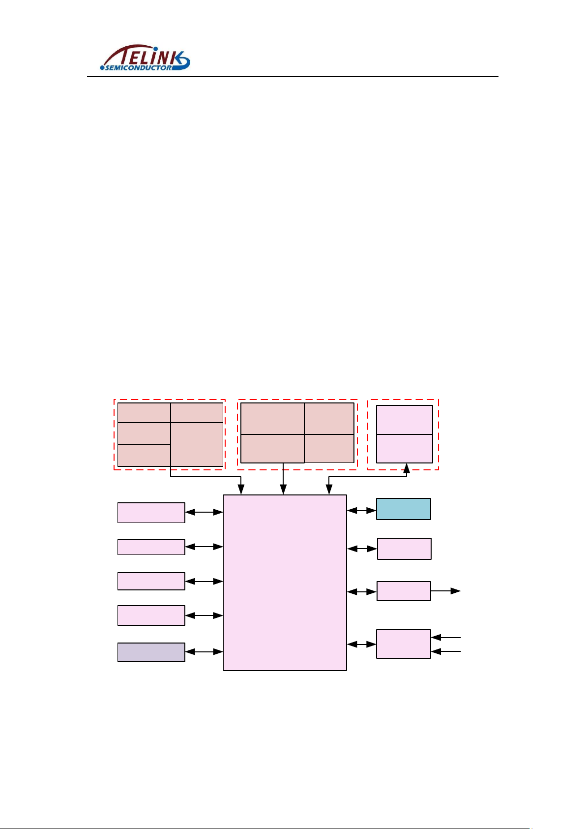
The TLSR8258 Dongle, which is based on Telink TLSR8258F512ET48 chip,
provides a Bluetooth LE wireless system.
The TLSR8258 Dongle integrates a power-balanced 32-bit
MCU, BLE /2.4GHz Radio, 64kB SRAM, 512kB internal Flash, 14bit ADC, 6-channel
PWM, flexible GPIO interfaces, and nearly all the peripherals needed for IoT (Internet
of Things) and HID (Human Interface Devices) application development
(e.g. Bluetooth Low Energy ).
The TLSR8258 Dongle supports standards and industrial alliance specifications
including Bluetooth Low Energy (up to Bluetooth 5), BLE Mesh, 6LoWPAN,
Thread, RF4CE, HomeKit, ANT and 2.4GHz proprietary standard.
Figure 1 Block diagram
PS-19012802-E1 5 Ver1.0.0

Telink 8258 Dongle Specification
1.2 Key features
Bluetooth 5 Compliant, 1Mbps, 2Mbps, Long Range 125kbps and 500kbps
2.4GHz proprietary 1Mbps/2Mbps/250kbps/500kbps mode with Adaptive
Frequency Hopping feature support
64kB on-chip SRAM with up to up to 32kB retention
512kB internal Flash
A rich set of I/Os: I2C, USB, Single wire slave, up to 10 GPIOs, UART with
hardware flow control support
6-channel PWM (Pulse Width Modulation) output
Rx sensitivity: -98dBm@BLE 1Mbps
RSSI monitoring with +/-1dB resolution
Power supply: 1.8V~3.6V (Battery) or 4.5V~5.5V (USB)
TX mode: 19.1mA@12dBm Tx power
RX mode: 12mA
1.3 Mechanical and PCB fabrication Specifications
PCB dimension: 51mm*18.5mm*1.0mm
PCB layer: 2 layers
Dielectric constant: 4.2
Impedance: 50Ω
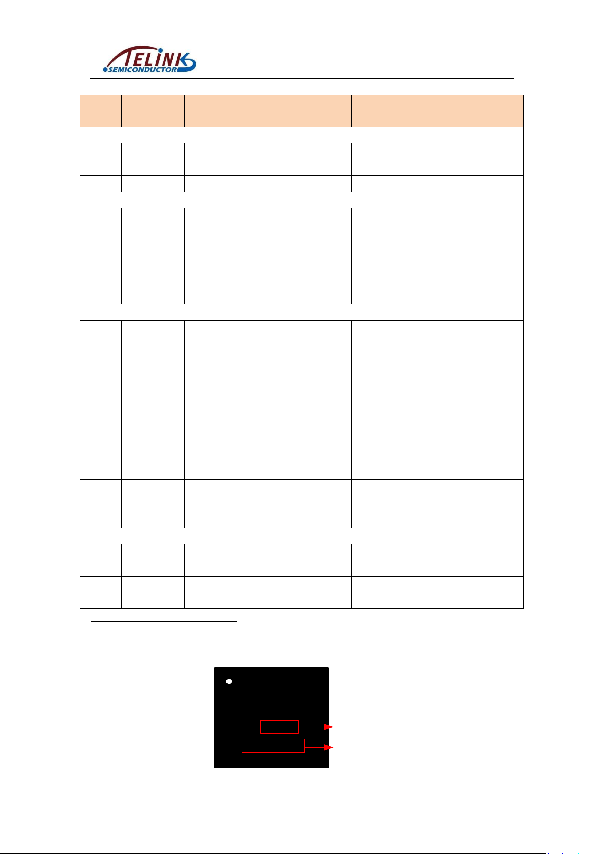
Figure 2 TLSR8258 Dongle photo
PS-19012802-E1 6 Ver1.0.0

Telink 8258 Dongle Specification
Figure 3 Mechanical dimensions
1.4 Pin layout
Figure 4 Pin layout for GPIO interface
PS-19012802-E1 7 Ver1.0.0
Telink 8258 Dongle Specification
Pin No
Dongle Pin
Name
Chip Pin Name
Description
J5
1
TL_A0
PWM0_N/UART_RX/PA<0>
PWM0 inverting output / UART_RX /
GPIO PA[0]
2
TL_D7
UART_TX /PD<7>
UART_TX / GPIO PD[7]
J9
1
TL_C3
PWM1/UART_RX/I2C_SCK/XC32K_I/
PC<3>
PWM1 output / UART_RX / I2C serial
clock / (optional) 32kHz crystal input /
GPIO PC[3]
2
TL_C2*1
PWM0/UART_TX/I2C_SDA/XC32K_O/
PC<2>
PWM0 output / UART_TX / I2C serial
data / (optional) 32kHz crystal output /
GPIO PC[2]
J10
1
TL_B2
PWM5/UART_CTS/RX_CYC2LNA/
lc_comp_ain<2>/sar_aio<2>/PB<2>
PWM5 output / UART_CTS / Control
external LNA / Low power comparator
input / SAR ADC input / GPIO PB[2]
2
TL_B3
PWM0_N/UART_RTS/TX_CYC2PA/
lc_comp_ain<3>/sar_aio<3>/PB<3>
PWM0 inverting output / UART_RTS /
Control external PA / Low power
comparator input / SAR ADC input /
GPIO PB[3]
3
TL_B4
PWM4/lc_comp_ain<4>/
sar_aio<4>/PB<4>
PWM4 output / Low power
comparator input / SAR ADC input /
GPIO PB[4]
4
TL_B5
PWM5/lc_comp_ain<5>/
sar_aio<5>/PB<5>
PWM5 output / Low power
comparator input / SAR ADC input /
GPIO PB[5]
J11
1
TL_C6
RX_CYC2LNA/ PWM4_N/PC<6>
Control external LNA /PWM4 inverting
output / GPIO PC[6]
2
TL_C7
TX_CYC2PA/ PWM5_N/PC<7>
Control external PA /PWM5 inverting
output / GPIO PC[7]
1
TLSR8258
F512ET48
THYYWW
EP6070.20
Date Code:
Year + Week
Lot No.
Table 1 Pin definition
For 8258 chips with lot No. of EP5682.20 (VID=0x01, 1827 ≤ Data code < 1844), since PC2 is pulled down by an
internal diode, all of its functions cannot act normally.
For 8258 chips with lot No. of EP6070.20 (VID=0x03, Date code≥1844), PC2 function bug has already been fixed.
PS-19012802-E1 8 Ver1.0.0

Telink 8258 Dongle Specification
J8
Connect USB interface with PC USB
Method 2: Supply power via USB
J6 1 3
Connect PIN3 with 3.3V
Connect PIN1 with GND
Method 1: Supply power via battery
2 Pin Connection Guide
2.1 Supply power
There are two methods supported to supply power for the TLSR8258 Dongle.
1) Supply power via battery:
Connect PIN1 and PIN3 of J6 with GND and 3.3V of power, respectively.
Note: There is no need to connect any header with jumper cap. Make sure the
cap is removed from J8.
2) Supply power via USB interface:
Make sure one jumper cap is connected on J8 of TLSR8258 Dongle.
Connect the USB interface of the TLSR8258 Dongle with PC USB.
Figure 5 Connection chart to supply power
PS-19012802-E1 9 Ver1.0.0

Telink 8258 Dongle Specification
J6
Connect PIN2 with SWM of TLSR8266BR56
2
2.2 Download firmware
To download firmware into TLSR8258 Dongle, first make sure the TLSR8258
Dongle is supplied with power normally (please refer to section 2.1).
Then connect J6 PIN2 (SWS) of the TLSR8258 Dongle with SWM of a burning
EVK (TLSR8266BR56). Meanwhile, connect the miniUSB interface of the burning EVK
with PC USB.
Figure 6 Connection chart to download firmware
PS-19012802-E1 10 Ver1.0.0

Telink 8258 Dongle Specification
Connect J1
Connect spectrum analyzer
J1
2.3 Test RF signal
To test RF signal of TLSR8258 Dongle, first make sure the TLSR8258 Dongle is
supplied with power normally (please refer to section 2.1).
The J1 should be connected with a spectrum analyzer via a RF cable (supplied by
Telink).
Figure 7 Connection chart to test RF signal
PS-19012802-E1 11 Ver1.0.0

3 Electrical Specifications
Item
Sym.
Min
Typ.
Max
Unit
Condition
Power-supply voltage
VDD
1.8
3.3
3.6
V
battery as
power supply
VBUS
4.5
5.0
5.5
V
USB as power
supply
Operating Temperature
Range
T
Opr
-40
85 oC
Item
Sym.
Min
Typ.
Max
Unit
Condition
Tx current
ITx
-
19.1 - mA
Continuous Tx transmission,
12dBm output power
Rx current
IRx - 12 - mA
Continuous Rx reception
3.1 Recommended operating condition
Table 2 Recommended operation condition
Telink 8258 Dongle Specification
3.2 DC characteristics
Test Condition: All tests below are done at room temperature (T=25℃) and 3.3V
battery power supply (For pin connection to supply power, refer to section 2.1).
Test equipment: Multimeter, Spectrum analyzer
DUT FW: EMI binary file
Table 3 DC characteristics
PS-19012802-E1 12 Ver1.0.0

3.3 RF performance
BLE PHY
Frequency (MHz)
Packet Type
Packet Length
RX Sensitivity (dBm)
1Mbps
2402
PRBS9
37
-98.9
2440
-98.9
2480
-98.6
Frequency (MHz)
RX Sensitivity (dBm)
2405
-100.2
2450
-99.7
2480
-102
2
3
3.3.1 Receiver sensitivity
Test equipment: BLE- CMW500
DUT FW: BQB binary file
Table 5 BLE Receiver Sensitivity*2
Table 6 IEEE802.15.4 Receiver Sensitivity*3
Telink 8258 Dongle Specification
3.3.2 PHY performance
BLE test equipment: CMW500
IEEE802.15.4 test equipment: FSQ8
DUT FW: BQB binary file
For actual sensitivity level of various BLE modes, please refer to Bluetooth 5 specification: Packet
number=10000, PER≤30.8%.
For actual sensitivity level of Zigbee mode, please refer to 802.15.4 specification: Packet number=10000, PER≤
1%.
PS-19012802-E1 14 Ver1.0.0

Telink 8258 Dongle Specification
Item
Frequency
(MHz)
Δf1avg
(kHz)
Δf2avg
(kHz)
Δf2/Δf1
Frequency
Deviation @ BLE
1Mbps
2402
248.00
232.00
0.94
2440
248.00
228.00
0.92
2480
249.00
229.00
0.92
Frequency
Deviation @ BLE
2Mbps
2402
488.06
448.34
0.92
2440
496.34
454.56
0.92
2480
483.67
442.59
0.92
Table 8 Frequency Deviation (Drift)
PS-19012802-E1 15 Ver1.0.0
3.3.3 Radiation performance
No.
Test Items
Test
Result
FCC (DUT FW: EMI binary file)
4
Tx Band Limit
Pass
Frequency
30MHz ~
2400MHz
2483.5MHz ~
25GHz
-
dB@100kHz
-38.3
-37.9
-
5
TX Mode Harmonic (Radiated), Peak
Pass
Frequency
4900MHz
7350MHz
9800MHz
dBm@1MHz
-42.9
-44.8
-46.8
6
TX Mode Harmonic (Radiated) 1-25GHz, Average
Pass
Frequency
4900MHz
7350MHz
9800MHz
dBm@1MHz
-42.9
-44.8
-46.8
7
Tx Radiated emission 30-1000MHz, Peak
Pass
Frequency
708.6MHz
-
-
dBm@100kHz
-70- -
8
Tx Radiated emission >1GHz, Average
Pass
Frequency
2.3692GHz
4900MHz
7350MHz
dBm@100kHz
-52
-42.9
-44.8
9
RX Mode Spurious Emission (25MHz ~ 25GHz)
Pass
Frequency
431MHz
2392MHz
-
dBm@100kHz
-76
-59.3
-
DUT: C1T139A3_V2_0A
DUT FW: EMI binary file
Test condition: 3.3V, 25℃
Test equipment: FSQ26
Match network: See Table 10 BOM table
Table 9 Test result
Telink 8258 Dongle Specification
PS-19012802-E1 16 Ver1.0.0

4.2 PCB layout
Telink 8258 Dongle Specification
Top view
Bottom view
Figure 9 PCB layout
PS-19012802-E1 19 Ver1.0.0

Telink 8258 Dongle Specification
4.4 32kHz XTAL
The TLSR8258 Dongle supports 32kHz external crystal oscillator (corresponding
to PC2, PC3).
FCC STATEMENT
This device complies with Part 15 of the FCC rules. Operation is subject to the following two
conditions: 1) this device may not cause harmful interference, and 2) this device must accept any
interference received, including interference that may cause undesired operation.
Changes or modifications not expressly approved by the party responsible for compliance could
void your authority to operate the equipment.
PS-19012802-E1 20 Ver1.0.0
 Loading...