

SYSTEM OVERVIEW
Front Panel
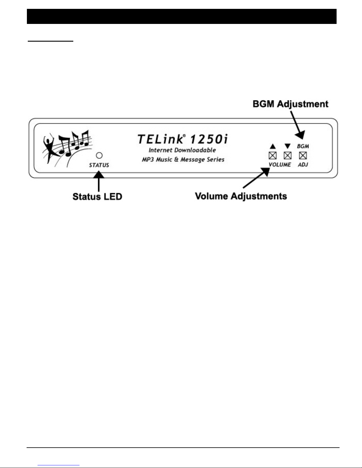
The Status LED, Volume adjustments, and BGM adjustments are located on the
front panel.
Figure 1 - Front Panel Diagram
Status LED – Lights to indicate the current operation status of the unit.
Volume Adjustments – Used to control the Volume locally, if permitted to do
so by your dealer. Also used in Connect On Demand situations (see
page 10).
BGM Adjustment – Used to control the BGM Volume locally, if permitted to
do so by your dealer.
TELink 1250i 6 8/17/2004
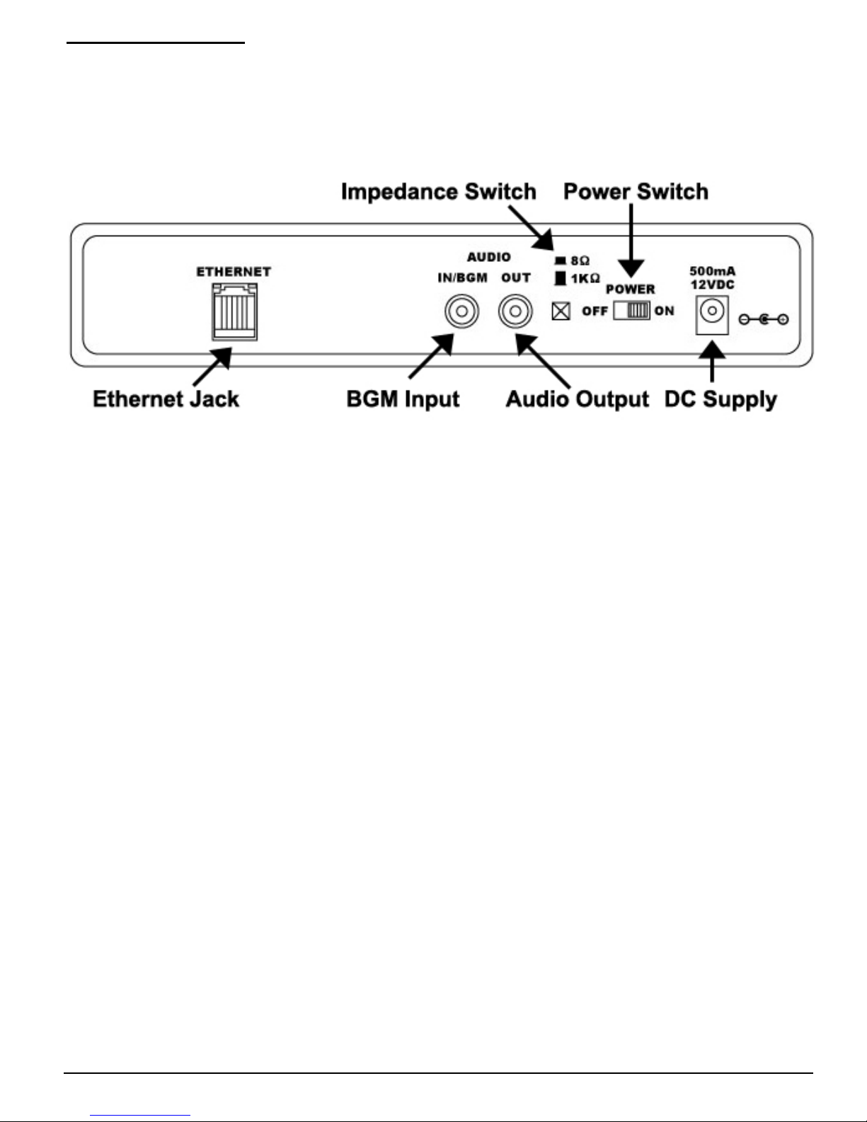
Connections Panel
The back side panel is where the connectors are for external equipment
including the Power Supply, Ethernet jack, and the external audio system that
receives the TELink
®
1250i 's output. Also located here are the Impedance
Switch and the Power Switch.
Figure 2 - Side Panel Diagram
Ethernet Jack – Used to connect to your Local Area Network (LAN).
BGM Input – Used to connect to an external BGM source.
Audio Output – Select one of the following Impedances with the Impedance
Switch.
8Ω Audio Output – Used to connect an external 8 Ohm speaker or
headphones.
1KΩ Audio Output – Used to connect to an external audio system such
as a KSU/PBX Phone System or an amplifier.
Power Switch – Used to turn the unit Off/On.
Power Supply – Used to supply power to the unit.
TELink 1250i 7 8/17/2004
INSTALLATION
Step 1 – Connections
Locate the TELink® 1250i within 6 feet of an 110VAC outlet. The unit is designed
to be placed on a flat, level surface or securely mounted on a wall. Be sure to
leave clearance for connections and adjustments.
Important:
monitors and fluorescent lights may interfere with message loading, so locate
the unit at least a few feet away from such devices.
To help protect against power surges and other electrical problems, the use of a
quality surge suppressor strip (which is different from a standard multi-outlet
power strip) is strongly recommended. Damage caused by power surges,
lightning, or other electrical problems are not covered under warranty.
Devices that emit strong electromagnetic fields such as computer
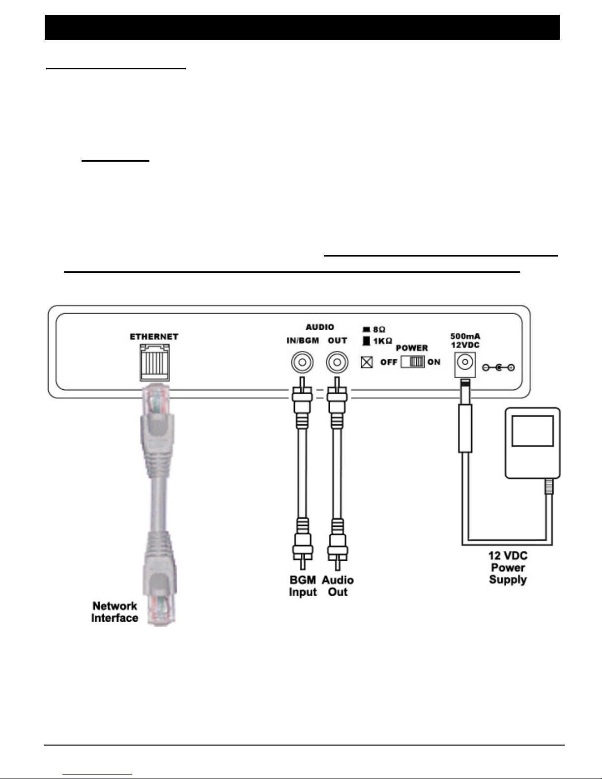
Figure 3 - Installation Diagram
TELink 1250i 8 8/17/2004

Connection Instructions
1. Turn the power switch OFF. Plug the included power supply into a normal
110VAC wall outlet, and the opposite end into the TELink
®
1250i. Only use
the power pack provided with the unit (12VDC, center pin positive). Many
power supplies look alike, but provide different output. Using the wrong one
voids your warranty and may damage the unit.
2. Connect the audio output jack to the external audio system input using a
mono RCA-to-RCA cable (included). If the external audio system does not
have an RCA-style input, use the included RCA to 1/8 inch adapter. Be sure
to select the right impedance before turning the unit on.
3. NOT REQUIRED FOR OMNI-Connect the BGM using a mono RCA-to-RCA
cable (included). If the BGM source does not have an RCA-style output, use
the included RCA to 1/8 inch adapter. This step is optional and only required
if you are using Background Music.
4. Connect the Ethernet jack to your Local Area Network. (LAN) The unit is
factory DHCP enabled and should obtain an IP address automatically. See
the local Network Administrator or the Quick Install Guide on the back page of
this manual for assistance.
5. Turn the unit on.
6. Call Omni to confirm connectivity between the unit and their server(s)
via the Internet.
Step 2 – Adjust Volume
The Volume buttons on the front of the unit are used to adjust the Volume to a
comfortable listening level.
TELink 1250i 9 8/17/2004

PLAYBACK OPERATION
Continuous Play
The TELink® 1250i plays back all dealer-loaded music and messages over your
sound system or MOH port continuously. The unit automatically checks your
dealer’s server(s) on a routine basis for new music and messages as they
become available.
Volume Adjustments
If permitted by your dealer, the Volume may be adjusted using the Volume
buttons on the front of the unit.
Connect On Demand
Connect On Demand allows you to force an instant connection to your dealer’s
server(s) to check for new music and messages outside of its routine ConnectBack cycle. To perform a Connect On Demand, turn the power to the unit on
while depressing the Volume down (middle) button. Release the button once
the Status LED turns Orange.
Status LED Indications
Indication Meaning
Solid Red Unit has no messages.
Solid Green Unit has messages loaded and is playing audio.
Solid Orange
Blinking Orange
Unit is currently connected to dealer’s server and is
downloading new music and messages.
Unit is establishing/disconnecting a connection to the
dealer’s server.
Table 1 – Status LED Indications
TELink 1250i 10 8/17/2004

WALL MOUNTING INSTRUCTIONS
Using the included wall mount bracket and two screws, secure the unit onto the wall
where you wish to mount it.
Consider the weight of the TELink
®
1250i when choosing a mounting wall. Make
sure the wall’s construction is sufficiently strong to support the weight of the unit
securely. Make sure both screws are driven into sturdy supports.
When mounting the unit, be sure that the front panel and Status LED is clearly
visible for you to see.
FLAT SURFACE INSTRUCTIONS
Place the unit on a sturdy table, away from any obstructions that may disrupt it.
The unit may be placed in any direction, however, be sure that the front panel and
Status LED is clearly visible for you to see.
TELink 1250i 11 8/17/2004

INSTALLER/CUSTOMER QUICK INSTALL GUIDE
Step 1 : Unpack the contents of the TELink
items:
- TELink
®
1250i
- Installer Utilities CD
- Power pack
- Network cable
- RCA to RCA cord
- RCA to 1/8” adapter
- Wall mount kit
- Manual and/or Quick Install Guide
Step 2: Connect the TELink
Step 3: Connect the TELink
Step 4: Turn the unit ON.
Step 5: The TELink
®
1250i has been factory-set for DHCP and should obtain an IP address
®
1250i to power using the supplied power pack.
®
1250i to your network using the supplied network cable.
automatically.
Step 6: Turn the unit OFF.
Step 7: Wait 5 seconds.
Step 8: Turn the unit ON while pressing the VOLUME DOWN button.
Step 9: Release the button when the status LED turns ORANGE.
Step 10: Call your dealer to confirm that the unit has made a connection* to their server.
Step 11: Connect the RCA output to your music-on-hold port or PA system.
Step 12: Verify the status LED is green and audio is playing to your MOH port or your PA
speakers.
* You can also verify connection to the dealers/service provider’s server by using the
“Connection Tester” application that is included on the Installer Utilities CD.
IF YOU NEED TO SET A STATIC IP ADDRESS PLEASE READ BELOW
If you do not have a DHCP server, you will need to manually assign IP information to the
TELink
®
1250i using the Configuration Utility on the Installer Utilities CD.
Replace Step 5 above with the following:
Step 5a - Place the Installer Utilities CD on a computer on the local network.
Step 5b - Select the Configuator Utility from the pop-up menu.
Step 5c - The utility will automatically search the network and find the TELink
Step 5d - You can now assign it an available static IP address.
Step 5d - If the utility can not find the TELink
address and IP information. The MAC address label can be found on the bottom of
the unit.
Step 5e - Press EXIT and continue with installation.
INSTALLATION OF THIS PRODUCT SHOULD BE DONE BY A QUALIFIED INSTALLER!
PLEASE CALL YOUR DEALER FOR SUPPORT ON THIS PRODUCT
®
1250i package - You should have the following
®
1250i.
®
1250i, click MANUAL ENTRY and enter the MAC
!
TELink 1250i 16 8/17/2004
 Loading...