

Page 1

TELINDUS 1134/1135 ADSL
ROUTER/SWITCH 4P
QQuuiicckk SSttaarrtt
Quick Start Manual
Version 2.0
Telindus Technical Publications - Geldenaaksebaan 335 - B-3001 Leuven Belgium - Tel. +32 16 382011
Page 1 of 16
Page 2

QQuuiicckk SSttaarrtt
Copyright notice
The information and descriptions contained in this publication are the property of
Telindus. Such information and descriptions must not be copied or reproduced by any
means, or disseminated or distributed without the express prior written permission of
Telindus.
Disclaimer
This publication could include technical inaccuracies or typographical errors, for
which Telindus never can or shall be held liable. Changes are made periodically to the
information herein; these changes will be incorporated in new editions of this
publication. Telindus may make improvements and/or changes in the product(s)
described in this publication at any time, without prior notice.
Safety Warnings
Always observe standard safety precautions during installation, operation and
maintenance of this product. Only qualified and authorized service personnel should
carry out adjustment, maintenance or repairs to this instrument. Either the operator or
the user should perform no adjustment, maintenance or repairs.
The interfaces on the Telindus 1134/1135 ADSL ROUTER/SWITCH should only be
connected to circuit types as listed below:
Interface Connector Circuit
Line Interface RJ11 TNV-1
LAN Interface RJ45 SELV
Carefully read the safety instructions in this manual.
Warranty
Product warranty does not apply to damage caused by lightning, power surges
or wrong voltage usage.
Your feedback
Your satisfaction about this purchase is an extremely important priority to all of us at
Telindus. Accordingly, all electronic, functional and cosmetic aspects of this new unit
have been carefully and thoroughly tested and inspected. If any fault is found with this
unit or should you have any other quality-related comment concerning this delivery,
please submit the Quality Comment Form on our web page
http://www.telindus.com/accessproducts
.
Page 2 of 16
Page 3

QQuuiicckk SSttaarrtt
Conformity Statements
http://www.telindus.com/accessproducts
Hereby, TELINDUS declares that this TELINDUS 1134/1135 ROUTER/SWITCH is in
compliance with the essential requirements and other relevant provisions of Directive
1999/5/EC.
Bij deze verklaart TELINDUS dat deze TELINDUS 11134/1135 ROUTER/SWITCH in
overeenstemming is met de essentiële vereisten en andere relevante bepalingen van Richtlijn
1999/5/EC.
Par la présente, TELINDUS déclare que ce TELINDUS 1134/1135 ROUTER/SWITCH est en
conformité avec les exigences essentielles et autres articles applicables de la Directive
1999/5/EC.
Hiermit, TELINDUS erklärt daß dieser TELINDUS 1134/1135 ROUTER/SWITCH in
Fügsamkeit ist mit den wesentlichen Anforderungen und anderen relevanten Bereitstellungen
von Direktive 1999/5/EC.
Mediante la presente, TELINDUS declara que el TELINDUS 1134/1135 ROUTER/SWITCH
cumple con los requisitos esenciales y las demás prescripciones relevantes de la Directiva
1999/5/CE.
A TELINDUS declara que o TELINDUS 1134/1135 ROUTER/SWITCH cumpre os principais
requisitos e outras disposições da Directiva 1999/5/EC.
Col presente, TELINDUS dichiara che questo TELINDUS 1134/1135 ROUTER/SWITCH è in
acquiescenza coi requisiti essenziali e stipulazioni attinenti ed altre di Direttivo 1999/5/EC.
Με το παρόν, η TELINDUS δηλώνει ότι αυτό το TELINDUS 1134/1135 ROUTER/SWITCH
είναι συµµορφούµενο µε τις βασικές απαιτήσεις και µε τις υπόλοιπες σχετικές διατάξεις της
οδηγίας 1999/5/EC.
Products Choose a product Download certificates
Page 3 of 16
Page 4
QQuuiicckk SSttaarrtt
Safety instructions
IMPORTANT SAFETY INSTRUCTIONS
Unplug the unit from the wall power outlet before installing, adjusting or servicing.
ACHTUNG! WICHTIGE SICHERHEITSINSTRUKTIONEN
Vor sämtlichen Arbeiten am Gerät (Installation, Einstellungen, Reparaturen etc.) sollten Sie
den Netzstecker aus der Steckdose ziehen.
SAFETY WARNING
To avoid damage to the equipment, please observe all procedures described in this manual.
Ensure that the unit and its connected equipment all use the same AC power and ground, to
reduce noise interference and possible safety hazards caused by differences in ground or
earth potentials.
SICHERHEITSBESTIMMUNGEN
Um eine Beschädigung des Gerätes zu verhindern, beachten Sie bitte unbedingt die
Sicherheitsbestimmungen, die in diesem Abschnitt beschrieben werden.
Unpacking
Rough handling during shipping causes most early failures. Before installation, check the
shipping carton for signs of damage:
1. If the carton box is damaged, please place a claim with the carrier company
immediately.
2. If the carton box is undamaged, do not dispose of it in case you need to store the unit
or ship it in the future.
Selecting a site
WARNING
Always place the unit on its feet without blocking the air vents.
Do not stack multiple units directly onto each other, as stacking can cause heat build-up that
could damage the equipment.
ACHTUNG
Stellen Sie das Gerät niemals seitlich, sondern nur auf den Füßen auf und achten Sie darauf,
daß die Lüftungsschlitze an der Seitenverkleidung frei bleiben.
Stapeln Sie nicht mehrere Geräte direkt übereinander, dies kann zu einem Hitzestau führen.
Page 4 of 16
Page 5

QQuuiicckk SSttaarrtt
Contents
Introduction....................................................................................................................5
Minimum System Requirements....................................................................................5
ADSL Router Package...................................................................................................6
ADSL Router Overview ................................................................................................6
Typical ADSL Router Connections...............................................................................8
Step 1: Connecting the ADSL Router to Your Computer/Notebook ..........................10
Step 2: Configuring Your Ethernet Network Card .....................................................13
Step 3: Configuring Your Internet Browser.................................................................15
Step 4: Connecting to the Internet ..............................................................................16
Introduction
Thank you on your purchase of the TELINDUS 1134/1135 ADSL ROUTER
/SWITCH! This 4 Port Ethernet ADSL Router allows you to share high-speed
broadband ADSL connection with multiple PCs using a single device. With ADSL,
you can enjoy high-speed broadband connectivity for email, Internet surfing,
corporate access and continue to make phone calls using your existing phone line.
The 4 Port Ethernet ADSL Router can be connected to any computer/notebook with a
10/100 Base-T Ethernet card. For multiple users connection, you may connect your
computers/notebooks to the 4-port Ethernet swit ch on the ADSL Router at the same
time or expand the Ethernet connection of the ADSL Router with an E thernet Hub /
Switch. The Auto MDI/MDIX features automatic recognition of crossed or straight
UTP cables.
This documentation assumes that you have already installed an Ethernet card on your
computer/notebook.
Minimum System Requirements
• Pentium
• Ethernet card installed with TCP/IP Protocol
• OS independent for Ethernet (support for Windows based system only)
• Recommended Web Browser support:
Microsoft Internet Explorer 4.0 (or later versions)
Netscape® Navigator 3.02 (or later versions)
®
MMX 233MHz
Page 5 of 16
Page 6
QQuuiicckk SSttaarrtt
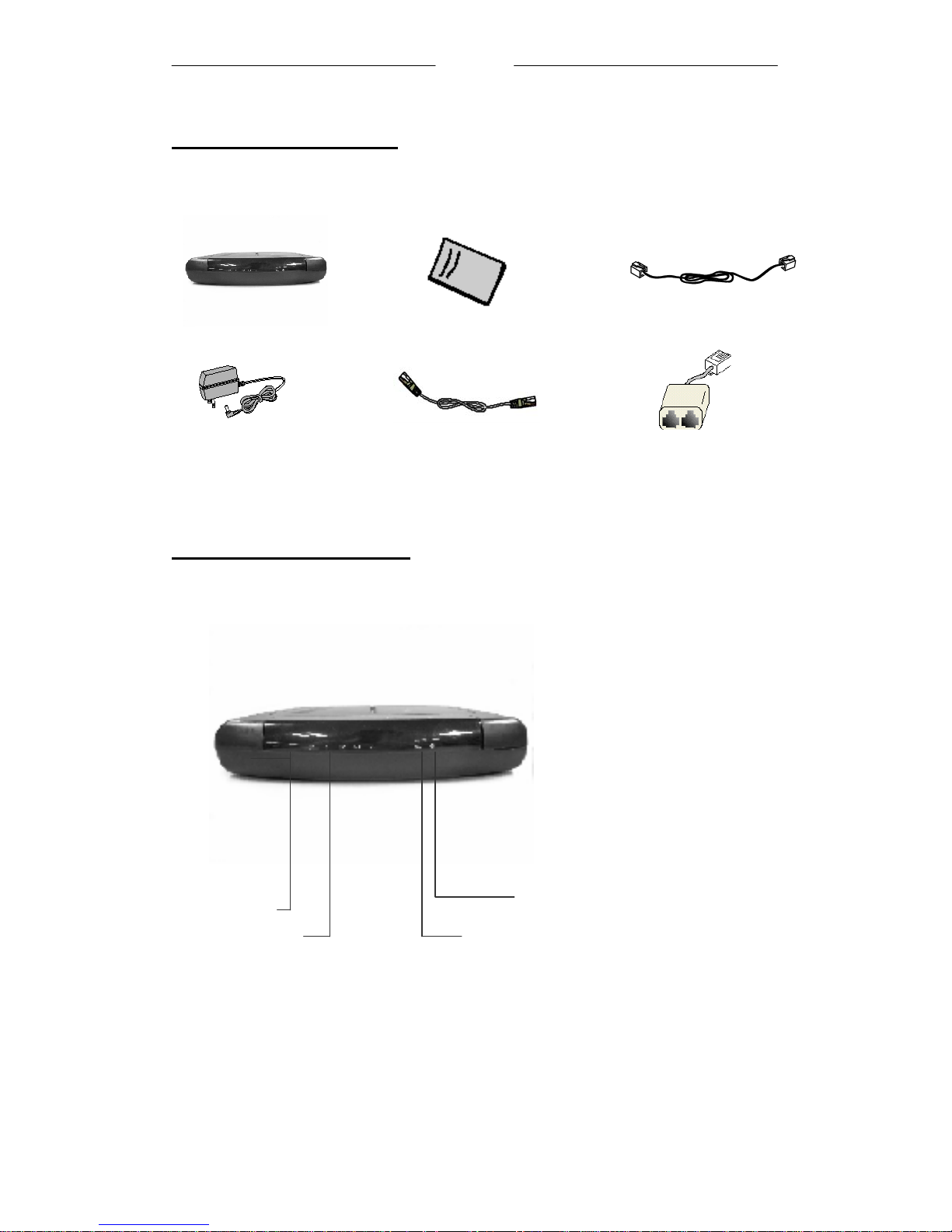
ADSL Router Package
For any missing items, please contact your dealer immediately.
ADSL Ethernet Router
Power Adapter (DC12V)
1Depending on your country of purchase, your package may or may not come with a POTS Splitter
and/or a second Telephone Cable. The POTS Splitter is required if you are connecting a Telephone
Set to the Ethernet Modem. Please refer to Step 1.2 - Connecting to the ADSL Line for details. POTSSplitter can also be obtained from your PTT or purchased from your dealer.
CAT-5 UTP Straight
Ethernet Network cable (RJ-45)
Quick Start
Telephone Cable (RJ-11)
POTS-Splitter1 (optional)
ADSL Router Overview
Front Indicators
③
④
② ③
① POWER
Lights up when power is supplied to the ADSL Router.
①
②
④
①
Page 6 of 16
Page 7
QQuuiicckk SSttaarrtt
② ETH/ACT
Lights up
when the Ethernet cable is properly connected from your ADSL Router to
the Ethernet Card.
Flickers when the ADSL is transmitting/receiving data.
DSL
③
Lights up when the ADSL connection is established.
Flickers when the ADSL Router is trying to establish a connection with the ADSL
Service Provider
Internet
④
Lights up when the PPP connection to the ISP is established.
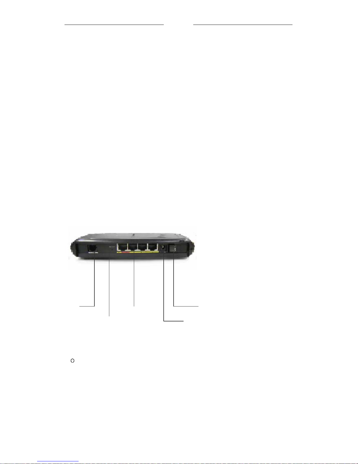
Back Panel
⑤ ①
③
④
POWER SWITCH
①
②
To power on or off the modem.
I - Indicates ON position
- Indicate OFF position
② DC IN
To connect to the Power Adapter that comes with your package.
③
ETHERNET
10/100 Base-T Ethernet jack (RJ-45) to connect to your Ethernet Network card or
Ethernet Hub / Switch.
Page 7 of 16
Page 8
QQuuiicckk SSttaarrtt
RESET
④
To reset your ADSL Router to factory default settings. (All customised settings that
you have saved will be lost!) Please refer to the below footer2 on how to activate the
reset function.
⑤ ADSL
Telephone jack (RJ-11) to connect to your Telephone Wall Socket (ADSL line).
2 To activate the reset function:
- Ensure that your ADSL Router is powered on.
-Use a paper clip or a pencil tip to depress the reset button and release.
At this point, the DSL indicator light will go off, followed by the ETHERNET indicators. The reset is in
progress.
- When the DSL indicator starts blinking, it means that the reset process is completed. The default
settings are now restored.
- ADSL line is established once the DSL indicator lights up.
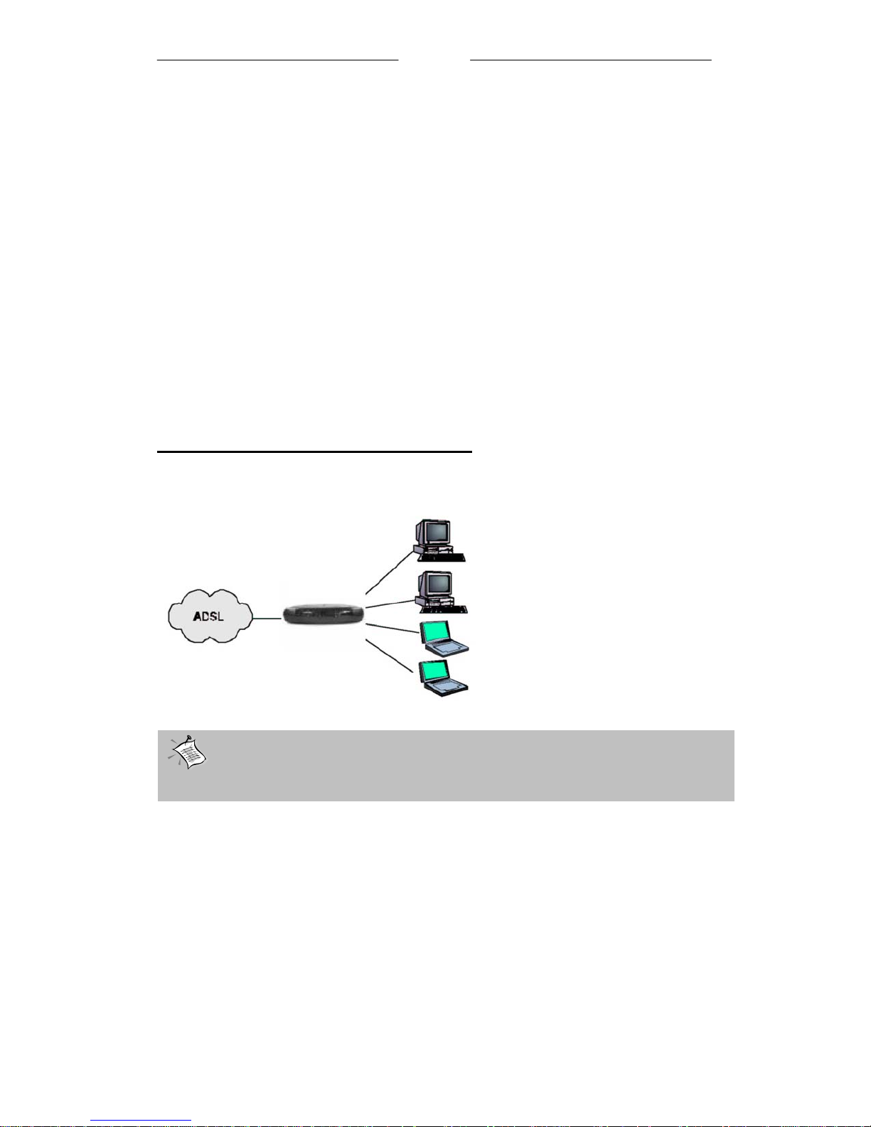
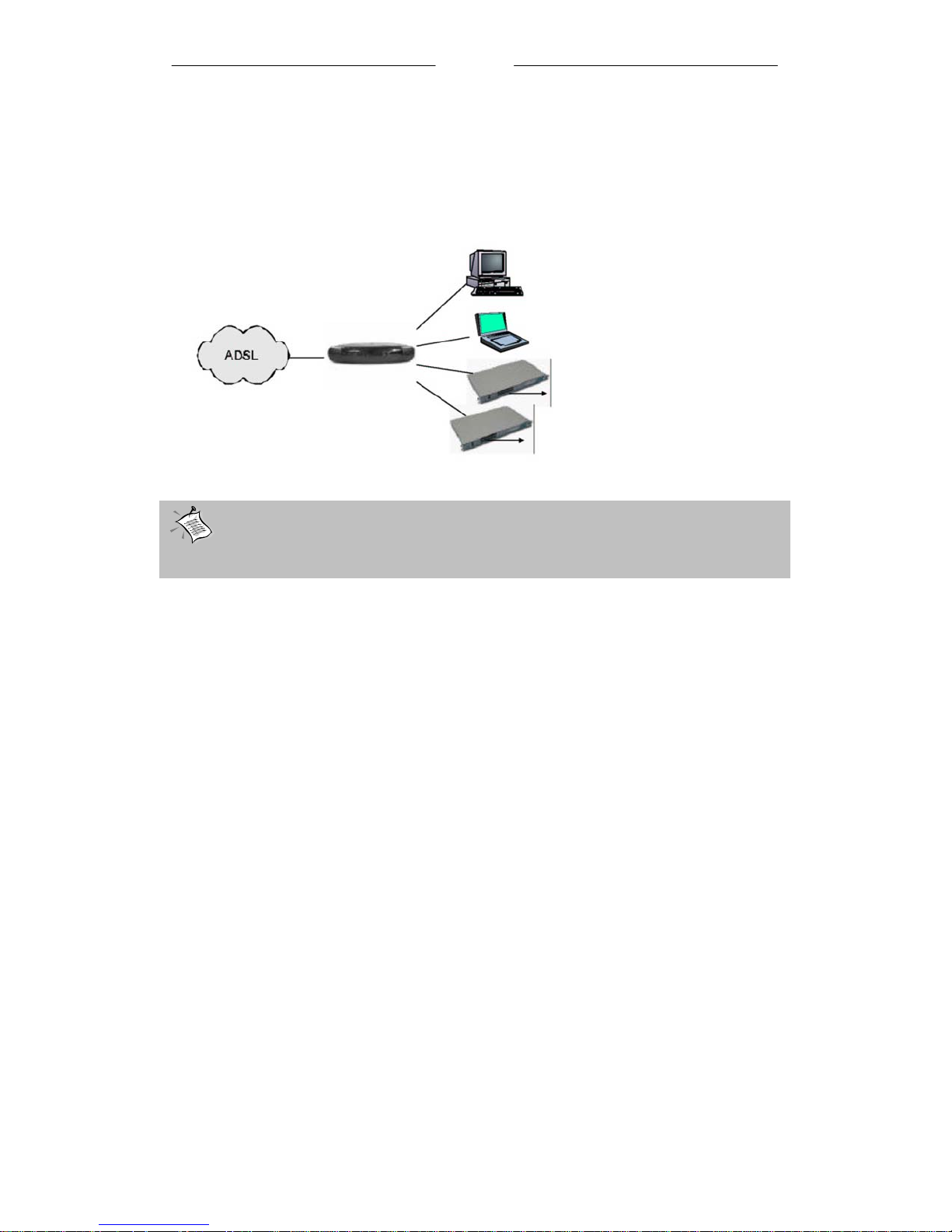
Typical ADSL Router Connections
Up to 4 PCs Connections
With the Auto MDI/MDIX feature, cross or straight UTP cable can be automatically
recognized.
ADSL
Computers or Notebooks with
Ethernet Network Cards
Page 8 of 16
Page 9
QQuuiicckk SSttaarrtt
For More than 4 PCs Connections
To connect to more than 4 computers/notebooks, you may further cascade to another
Ethernet Hub/Switch. For details on how to connect to the Ethernet Switch/Hub,
please refer to the documentation that comes with the Ethernet Hub/switch.
ADSL Router
Computers or Notebooks with
Ethernet Network Cards
To Computers or Notebooks
with Ethernet Network Ca rds
Ethernet
Switches/Hubs
To Computers or Notebooks
with Ethernet Network Ca rds
recognized.
With the Auto MDI/MDIX feature, cross or straight UTP cable can be
automatically
Page 9 of 16
Page 10
QQuuiicckk SSttaarrtt
S tep 1: Connecting the ADSL Router to Your
Computer/Notebook
! Power off your Computer/Notebook or/and any connected devices before
connecting to the ADSL Router!
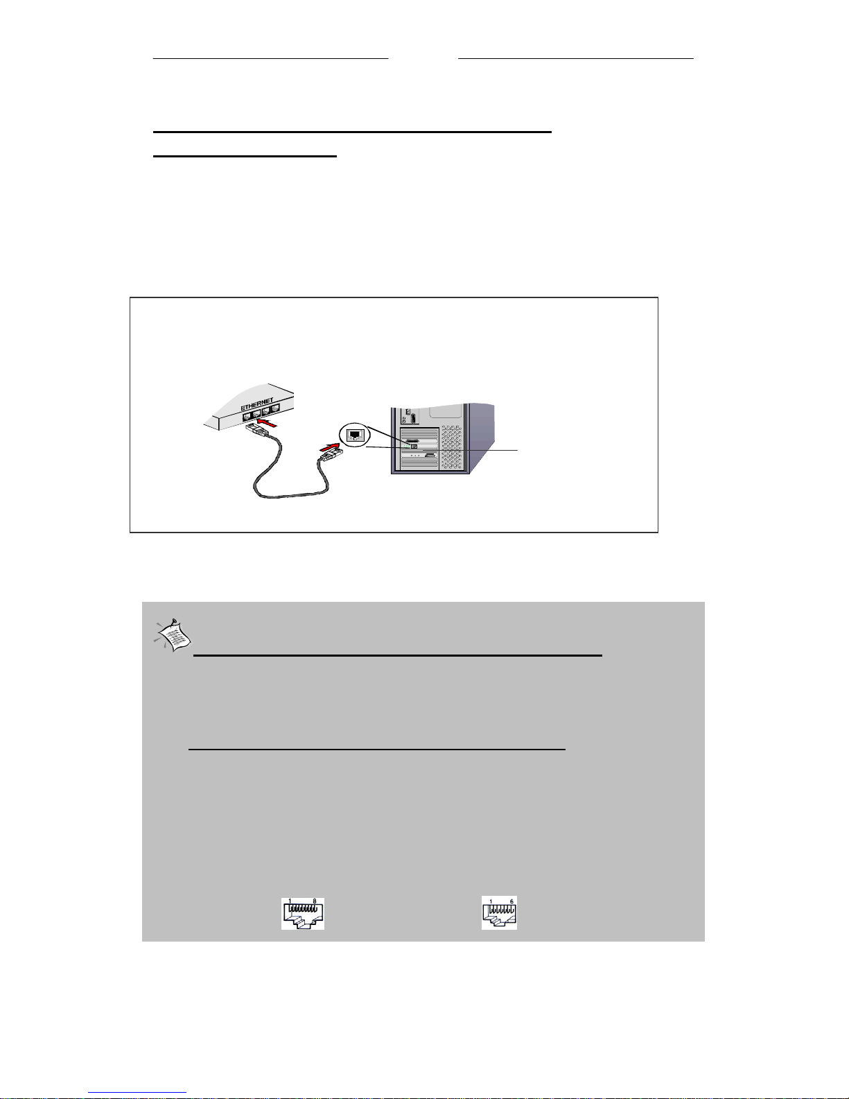
1.1 Connecting to the Ethernet
Connect your computer(s)/notebook(s) to the ADSL 4 Port Router as illustrated.
The following illustration shows the connection of a
single computer.
Back view of a computer
Ethernet Port
Back view of
the ADSL
(All the Ethernet Ports on the ADSL Router are Auto MDI/MDIX. Both Straight and Cross Ethernet
Network cables can be used).
Ethernet Network cable
Ethernet Network Card
NOT SURE HOW THE ETHERNET PORT LOOKS LIKE?
The following are some tips to help you locate your Ethernet Ports on your
Computer/Notebook. Alternatively, you may refer to the documentation that
comes with your Computer/Notebook.
Locating the Ethernet Port on your Computer/Notebook
Most Computers/Notebooks have labels describing the Ports. For Ethernet
Port, you will see ETHERNET, ETH or RJ45 labelled near the Port.
If your Computer/Notebook does not have such descriptions, try the
following.
- Picture A gives the illustration of an Ethernet Port. All Ethernet Ports have
8 conductors on it. Do not mistaken with the LINE Port (Picture B) that
has only 6 conductors.
- The Ethernet Port is slightly bigger than the LINE Port.
A. ETHERNET:
B. LINE:
Page 10 of 16
Page 11
QQuuiicckk SSttaarrtt
k
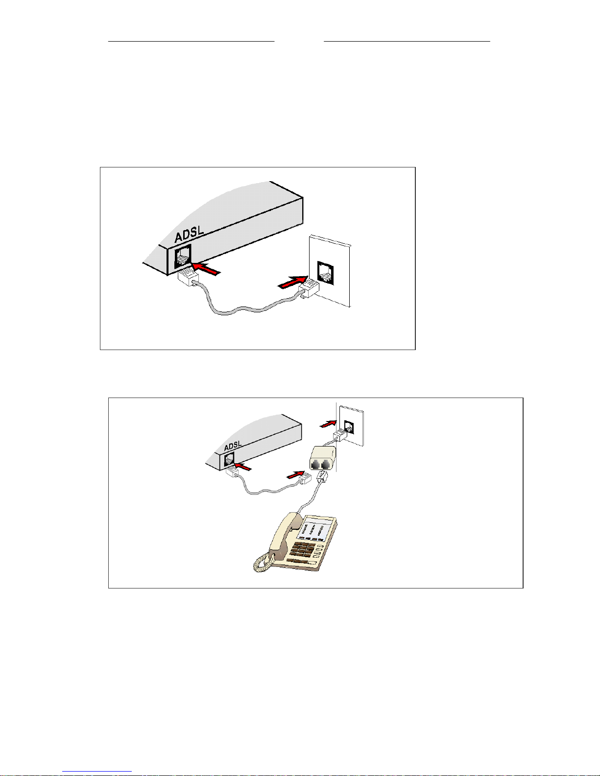
1.2 Connecting to the ADSL Line
To connect the ADSL Ethernet Modem to the ADSL line, perform Step 1.2(a).
To connect the
ADSL Ethernet Modem to the ADSL line and a Telephone Set
perform Step 1.2(b).
(a) To connect to the ADSL line
Back view of the
ADSL Router
Telephone cable
Telephone
Wall Socket
(b) To connect to the ADSL line and Telephone Set
,
Back view of the ADSL
Ethernet Modem
Telephone cable
Telephone Set
Telephone Wall Socket
POTS Splitter
Connect the Telephone set to the jac
labelled
telephone cable to the jack labelled LINE.
TEL
or
PHONE
and the
The POTS Splitter (with built-in Microfilter) is a device that allows you to connect
both your Telephone cable and Telephone Set to the same Telephone Wall Socket.
The device at the same time helps to eliminate background noise on the telephone line,
ensuring the best possible phone performance.
Page 11 of 16
Page 12
QQuuiicckk SSttaarrtt
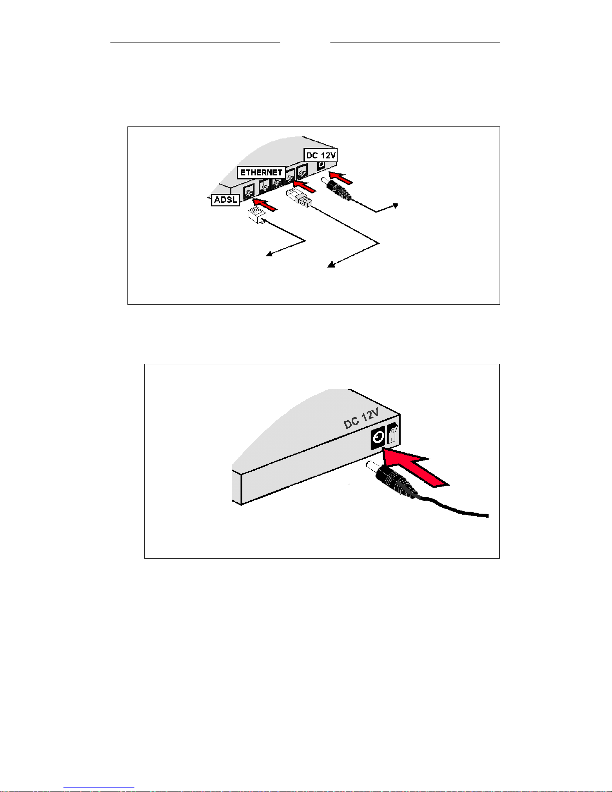
1.3 Checking Your Connections
Please check your connections before proceeding.
Back view of the
ADSL Router
To your Telephone Wall
Socket (ADSL line)
To the Ethernet Port on your
Computer(s)/Notebook(s)
1.4 Connecting to the Power Outlet
Back view of the
ADSL Router
To your Power Outlet
1.5 Powering On
Power on your ADSL Router
- Power on the Power Outlet that is connected to your ADSL Router.
- Power on your Computer(s)/Notebook(s).
Please proceed to Step 2.
Connect the other end of the Power
Adapter to the Power Outlet.
Page 12 of 16
Page 13
QQuuiicckk SSttaarrtt
K
Step 2: Configuring Your Ethernet Network Card
2.1 Configuring Your Ethernet Network Card
The following illustrated screen shots serve only as examples. For any
dissimilarities, please follow closely the instructions prompted on your
Computer.
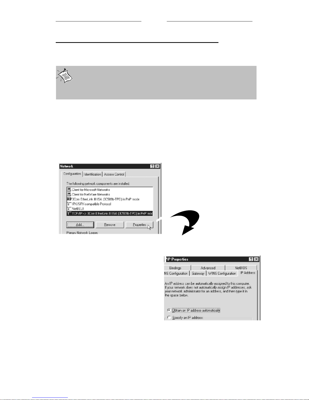
2.2 For Windows® 98 Second Edition / Windows® Me
I From your Windows desktop, right-click on the Network Neighborhood icon.
Select
IIii From the Configuration tab, select TCP/IP-> xxx where xxx refers to the
model of your Ethernet Card that is connected to your ADSL Router
Click Properties.
Properties
.
.
(This screen shot uses 3Com EtherLink
Ethernet card model as an example).
III Click the IP Address tab.
Click the option Obtain an IP
address automatically
click O
Ensure that your ADSL Router is powered on.
Restart your system.
to save the settings.
and
Proceed to
Step 3
.
Page 13 of 16
Page 14
QQuuiicckk SSttaarrtt
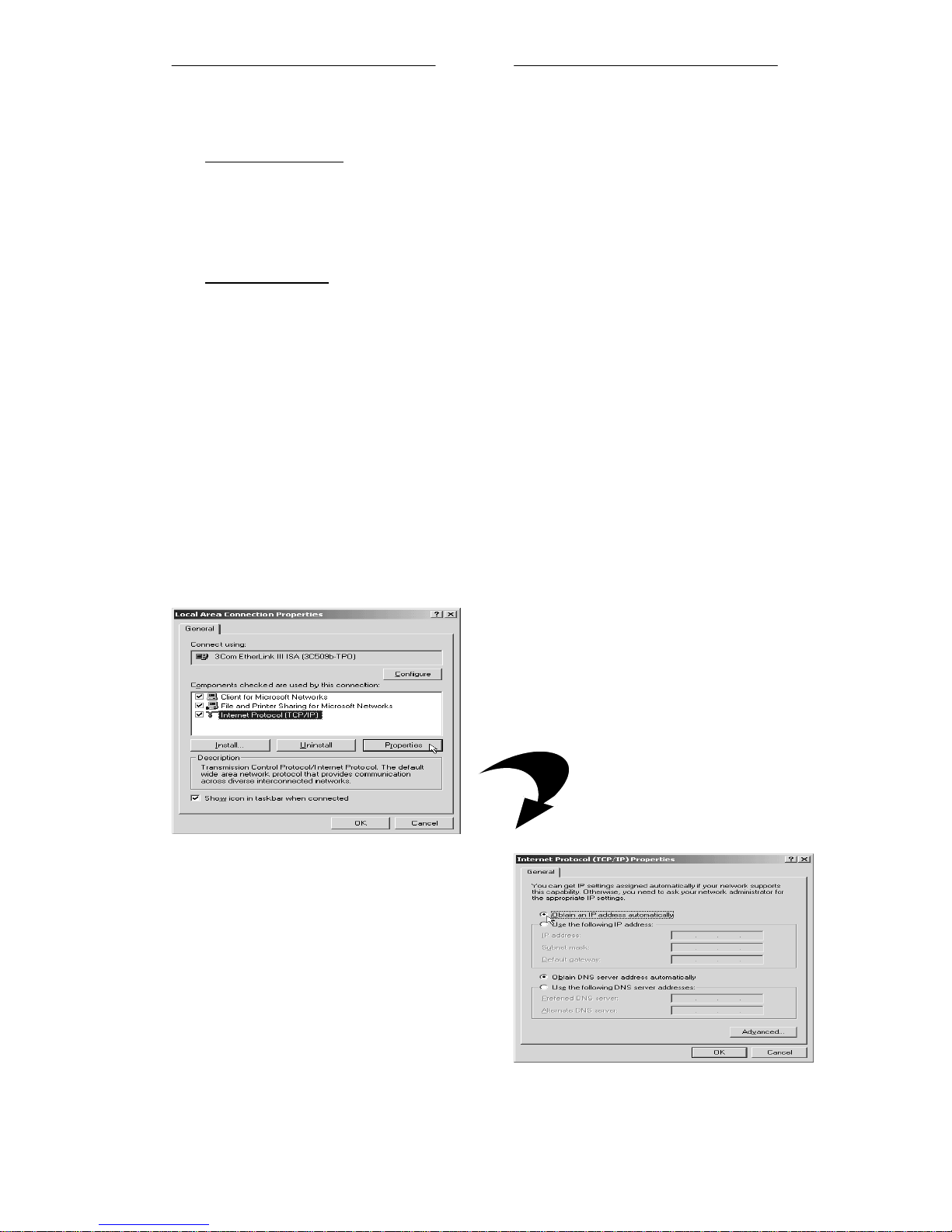
2.3 For Windows® 2000 / Windows® XP
®
I Windows
a) From your Windows desktop, right-click on the icon My Network Places
and select Properties.
b) At the Network and Dial-up Connections window, right-click on the
Local Area Connection icon and select Properties.
2000:
Windows® XP:
(Instructions are based on default Start menu option)
a) From your Windows desktop, click Start > All Programs > Accessories >
Communications > Network Connections.
b) Right-click on the Local Area Connection icon that reflects the model of
your Ethernet Card that is connected to your ADSL Router and click
Properties.
Ensure that the field
II
is connected to your ADSL Router.
(This is important especially if you have more than one Local Area Connection
icons displayed at the Network and Dial-up Connections / Network Connections
window. Ensure that you have selected the correct one.)
Select Internet Protocol (TCP/IP) and click Properties.
III Select the option Obtain an IP
address automatically
Connect Using
and click
indicates the model of your Ethernet Card that
(This screen shot uses 3Com
EtherLink Ethernet card model as an
example).
OK.
Click OK again to close.
Ensure that your ADSL Router is
powered on. Restart your system.
Proceed to Step 3.
Page 14 of 16
Page 15

QQuuiicckk SSttaarrtt
Step 3: Configuring Your Internet Browser
3.1 Microsoft® Internet Explorer™ (based on IE 5.5)
From your Windows desktop, double-click on your Internet Explorer icon
I
launch your Browser.
II From
III Select the Connection tab. Click the field, 'Never dial a connection'. (This
option will be grayed off if you have not installed an analog modem on your
computer/notebook before. Proceed with 3.1 IV).
IV Click the LAN Settings... button. Ensure that your Proxy Server is not enabled.
V Click OK to close the dialog box.
You may now proceed to
the Menu, click
Tools
Step 4
and select
to establish your Internet connection.
Internet Options.
to
®
3.2 Netscape
From your Windows desktop, double-click on your Navigator icon
I
your Browser.
II Depending on your Netscape versions, carry out one of the following instructions:
Click Options > Network Preferences.
Select Proxies. Ensure that the No Proxies option is selected.
OR
Click Edit > Preferences.
Select Advanced and click Proxies. Ensure that the option Direct Connection to the
Internet
III Click OK for changes to take effect.
You may now proceed to Step 4 to establish your Internet connection.
is enabled.
Navigator
to launch
Page 15 of 16
Page 16
QQuuiicckk SSttaarrtt
S tep 4: Connecting to the Internet
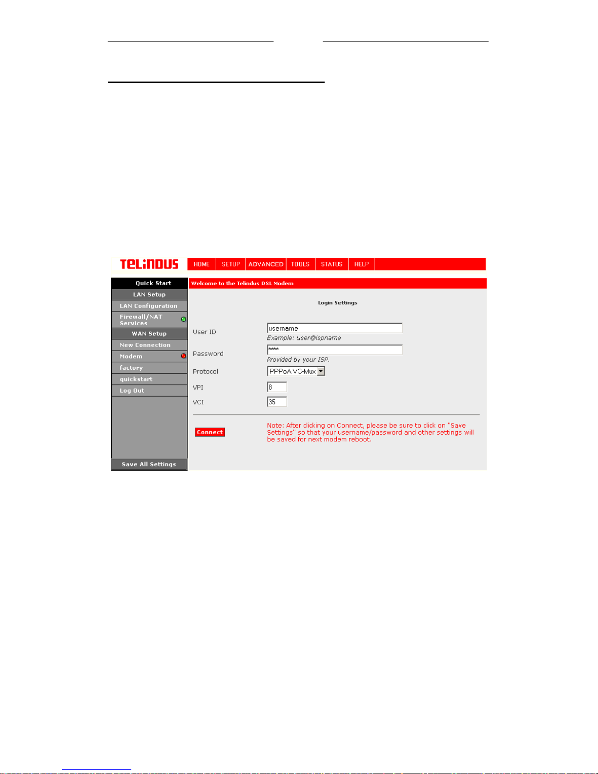
i From your Internet Browser, key in http://192.168.1.1 at the address bar and hit
<
ii You will be prompted for the Username and Password to login to the Web
(Not that this Username and Password is not the same as the username and p assword
>.
Enter
Management. Enter admin for the username and admin for the password
(factory defaults). Click OK.
given by your ADSL Service Provider to connect to the Internet).
iii
Click
SETUP
followed by
Quick Start.
Enter the relevant information given by your ADSL Service Provider. Typical
iv
information is UserName (User ID), Password, Protocol, VPI and VCI. Before
connecting, click on Save All Settings to keep these Provider Settings. Click then on
Connect
and normally you will be connected to the Internet.
In some special cases other settings might be needed to get a connection to the
Internet. In this case consult the Web User’s Guide on the CD. This guide also
describes tools and tips on what to do if you fail to connect to the Internet.
For a detailed description of the Web interface please refer to the
on the CD or on the Web site: www.telindusproducts.com
Page 16 of 16
Web User’s Guide
 Loading...