

Telindus 1132, 1133 User Manual

TELINDUS 1132/1133 Web Interface User’s Guide
Web Interface User’s Guide
TELINDUS 1 132/1 133 ADSL WIRELESS ROUTER 4P
Version 2.0 Page 1/57 December 2004

TELINDUS 1132/1133 Web Interface User’s Guide
Table Of Contents
1. INTRODUCTION...................................................................................................... 4
1.1 F
EATURES
............................................................................................................ 4
2. YOUR GATEWAY AT A GLANCE....................................................................... 6
2.1 P
2.2 LED
ORTS AND BUTTONS
DESCRIPTION
............................................................................................... 6
........................................................................................... 6
3. INSTALLING YOUR ADSL ROUTER.................................................................. 8
4. SETTING UP YOUR ADSL ROUTER (BASIC MODE)..................................... 9
4.1 L
4.2 Q
OG INTO YOUR
UICK START
..................................................................................................... 10
ADSL R
OUTER
.......................................................................... 9
4.3 SETUP .............................................................................................................. 12
4.3.1
4.3.2
4.4 C
4.4.1
4.4.2
4.4.3
4.5 C
4.5.1
4.5.2
4.5.3
4.6 ADVANCED (
4.6.1
4.6.2
4.6.3
4.6.4
4.6.5
4.6.6
4.6.7
4.6.8
4.6.9
4.6.10 LAN Isolation ........................................................................................... 36
4.6.11 Bridge Filters........................................................................................... 36
4.6.12 Web Filters.............................................................................................. 38
4.6.13 URL Filter................................................................................................. 39
4.6.14 Multicast................................................................................................... 40
4.6.15 Static Routing.......................................................................................... 41
4.6.16 Dynamic Routing.................................................................................... 42
4.6.17 Show Routes........................................................................................... 43
4.6.18 Access Control........................................................................................ 44
4.7 W
4.7.1
4.7.2
4.7.3
4.7.4
Wide Area Network connection............................................................ 12
Local Area Network connection...........................................................12
ONFIGURING THE
New Connection.....................................................................................13
Modify an Existing Connection ............................................................. 19
Modem setup.......................................................................................... 19
ONFIGURING THE
Configure a LAN group.......................................................................... 20
Ethernet Switch ...................................................................................... 23
Firewall/NAT Services........................................................................... 24
UPnP........................................................................................................ 25
SNTP........................................................................................................ 25
SNMP....................................................................................................... 27
DNS Proxy............................................................................................... 28
Dynamic DNS Client.............................................................................. 29
IP QoS...................................................................................................... 30
Port Forwarding...................................................................................... 33
IP Filters................................................................................................... 34
LAN Clients ............................................................................................. 35
IRELESS ACCESS POINT
Setup........................................................................................................ 46
Configuration........................................................................................... 47
Security.................................................................................................... 48
Management........................................................................................... 49
WAN................................................................................... 13
LAN....................................................................................20
FOR ADVANCED USERS ONLY
) ................................................... 25
.................................................................................. 46
Version 2.0 Page 2/57 December 2004

TELINDUS 1132/1133 Web Interface User’s Guide
4.8 TOOLS.............................................................................................................. 50
4.8.1
4.8.2
4.8.3
4.8.4
4.8.5
4.8.6
System Commands................................................................................ 50
Remote Log............................................................................................. 50
User Management.................................................................................. 50
Update Firmware.................................................................................... 50
Ping Test.................................................................................................. 52
Modem Test............................................................................................ 52
4.9 STATUS ........................................................................................................... 53
4.9.1
4.9.2
4.9.3
4.9.4
4.9.5
4.9.6
Network Statistics................................................................................... 53
Connection Status.................................................................................. 53
DHCP Clients.......................................................................................... 53
Modem Status......................................................................................... 53
Product Information................................................................................ 53
System Log............................................................................................. 54
5. APPENDIX A: TROUBLESHOOTING............................................................... 55
5.1 T
5.2 I
5.3 T
5.4 T
HE
CAN’T CONNECT TO THE
HE
HE
ADSL R
DSL L
DSL L
OUTER IS NOT FUNCTIONAL
OUTER
INK
INK
ADSL R
CONTINUES TO BLINK BUT DOES NOT GO SOLID
LED
IS ALWAYS OFF
LED
.......................................................... 55
......................................................... 55
................ 56
................................................................. 56
6. ADSL ROUTER TERMS....................................................................................... 57
Version 2.0 Page 3/57 December 2004

TELINDUS 1132/1133 Web Interface User’s Guide
1. Introduction
The TELINDUS 1132/1133 ADSL Wireless Router is a cost-efficient high-speed ADSL
bridge/router for SOHO or SME users.
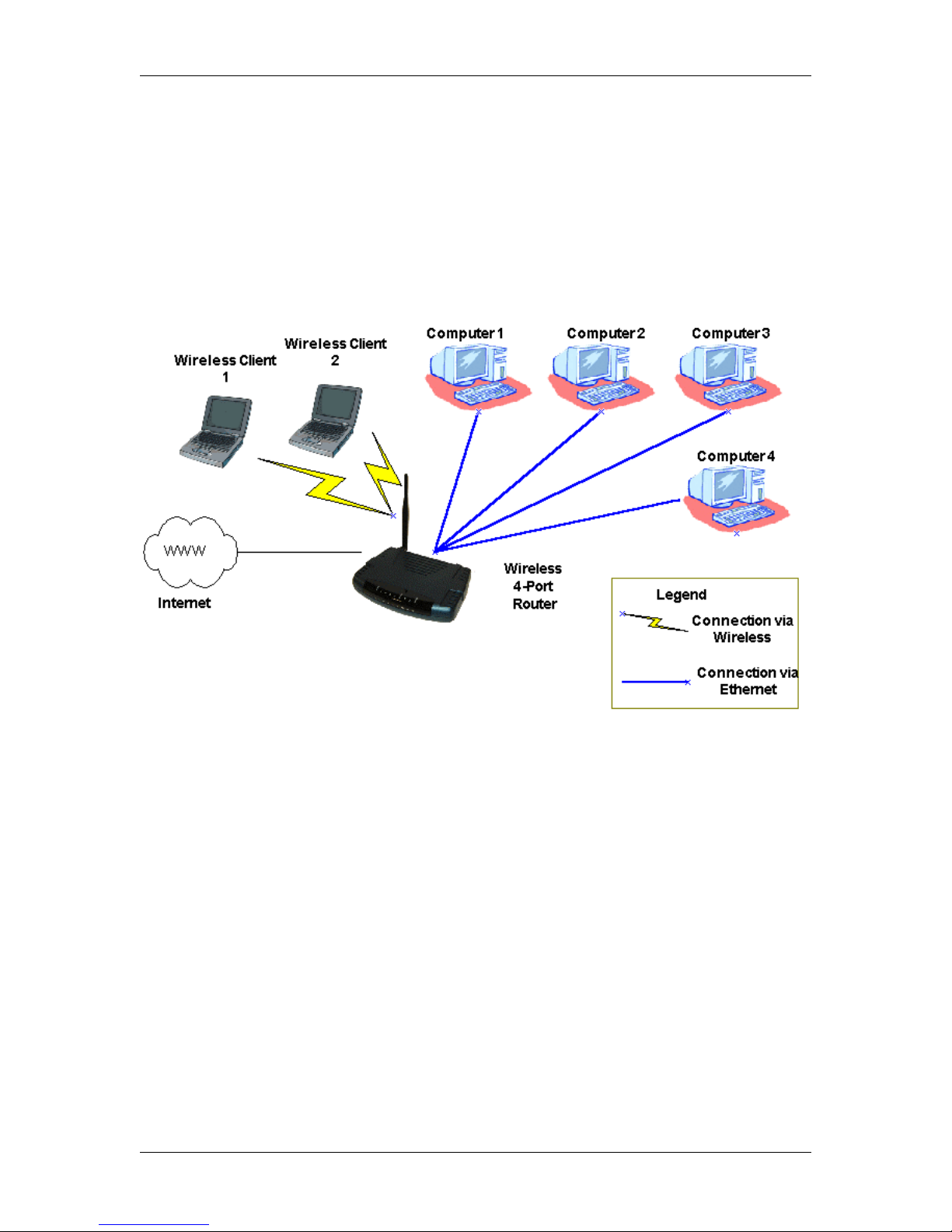
This full-featured product is specifically designed allow maximum of 4 Ethernet-workstations to
be connected to the Internet and directly connect to your local area network via a high speed
10/100 Mbps Ethernet Switch. In addition users using wireless workstations will be able to
connect to the Internet using 802.11g wireless technology. The ADSL Router has also full NAT
firewall and DMZ services to block unwanted users from accessing your network.
For game users, the ADSL Router had already pre configured for several low latency game ports.
Just click on the game you are playing on line and the rest is done for you
The ADSL Router is fully compatible with all PCs; as long as the PC supports an Ethernet
interface and is running a TCP/IP protocol stack, your PC can have high-speed WAN access.
So, plug in the ADSL Router (refer to Quick Start Guide), configure it (per your ISP’s
requirements) and enjoy the fast Internet access like never before. This router also provides
future proof functionality with higher data transmission rates with ADSL2, ADSL2+, Extended
Reach-ADSL support.
1.1 Features
ADSL/ATM Support
• ANSI T1.413 issue 2, ITU-T G.992.1 (G.dmt) and G.992.2 (G.lite) compliant
• ADSL2, ADSL2+, RE-ADSL compliant
• Rate Adaptive modem at 32 Kbps steps
• Dynamic Adaptive Equalisation to improve Carrier’s service area
• Bridge Tap Mitigation support
• ATM Layer with Traffic shaping QoS Support (UBR, CBR, VBR-rt, VBR-nrt)
• AAL ATM Attributes - AAL5
• Multiple PVC up to 8 support (Bridge Support)
• Spectral compatibility with POTS
• F5 OAM Loopback/Send and Receive
Encapsulation Support
• RFC2684 Bridge and Routed LLC and VC Mux support
• RFC2364 PPPoA Client support
• RFC2516 PPPoE Client support
• RFC2225/RFC1577 Classical IP Support
• Transparent Bridge Support
• PAP/CHAP for Password Authentication Support
Network Support
• Static IP, Dynamic RIP routing support
• IP/TCP/UDP/ICMP/ARP/RARP Application Support
• Network Address Translation (NAT)
• Port Mapping/Forwarding
• Easy setup of Port Forwarding rules for popular Games/Application
• NAT Application Level Gateway for popular applications
• DHCP Server/Relay/client
• DNS Relay Agent
• DMZ support
• Single Session IP Sec and PPTP/L2TP VPN pass through support
• PPP Always on with configurable timeout
Version 2.0 Page 4/57 December 2004

TELINDUS 1132/1133 Web Interface User’s Guide
• PPP Dial on Demand
• Universal Plug and Play Support
WLAN Support
• IEEE 802.11, 802.11B and 802.11G compliant
• Conforms to Wireless Ethernet Compatibility Alliance (WECA) Wireless Fidelity (Wi-Fi tm)
standard
•
Supports 802.11b and 802.11g simultaneously
• Support Direct Sequence Spread Spectrum (DSSS) technology
• Operating Range of >300 Meters (Open Air)
• WEP security, WPA security or 802.1X security
Management Support
• Web Based HTTP management GUI
• TFTP/FTP Support for Firmware Upgrade
• Web Based Firmware Upgrade (Local)
• Soft Factory Reset Button via Web GUI
• Diagnostic Test (DSL, OAM, Network, Ping Test)
• Telnet/CLI (Read Only)
• Syslog Support
• Firmware upgrade-able for future feature enhancement
Security Support
• NAT for basic Firewall support
• Packet Filtering Firewall Support
• Stateful Packet Inspection Support
• IP Flters
• Bridge Filters (up to 20 Rules)
• Protection against Denial of Service attacks
• Password Authentication to Modem
External Connectors:
• 1 x RJ-11 Telephone socket for ADSL line
• 4 x RJ45 for 10/100Base-T Ethernet (MDI-X)
• 1 x USB 1.1 Type B
• 1 x DC Jack for Power Input
• 1 x Factory Default Reset Button
• 1 x On/Off Power Switch
• 1 x Co-axial Connector for Detachable 180 degree Rotate-able 2.4Ghz 3 dBi Antenna
Platform Support:
• Windows 98SE
• Windows ME
• Windows 2000
• Windows XP
• Windows 2003
Version 2.0 Page 5/57 December 2004

TELINDUS 1132/1133 Web Interface User’s Guide
2. Your gateway at a glance
The ADSL Ethernet & USB Combo may have different ports and LEDs. Let’s take a look at the
different options. Depending upon your model, it may have some or all of the features listed
below.
2.1 Ports and buttons
Reset and Restore to Factory Defaults: The restore to factory defaults feature will set the
ADSL Router to its factory default configuration by resetting the ADSL Router. You may need to
place the ADSL Router into its factory defaults if the configuration is changed, you loose the
ability to interface to the ADSL Router via the web interface, or following a software upgrade,. To
reset the ADSL Router, simply press the reset button for about ~ 10 seconds. The ADSL Router
will be reset to its factory defaults and after about 30 ~ 40 seconds the ADSL Router will become
operational again. It is also possible to go to Factory defaults using the System Commands
screen under TOOLS.
LAN (local area network) E1 to E4 port(s): connect to Ethernet network devices, such as a PC,
hub, switch, or routers. Some ADSL Router came with a single LAN connection and some come
with four LAN connections. Depending on the connection, you may need a cross over cable or a
straight through cable.
Power is where you connect the power. Make sure to observe the proper power requirements.
The required voltage is 9 volts DC @ 1 Amp.
USB (universal serial port): connects to a PC’s USB port. The ADSL Router only supports
Window’s based PCs via an RNDIS driver (included in the software).
DSL port: This is the WAN interface that connects directly to your phone line.
2.2 LED description
1. POWER
Lights up when power is supplied to the ADSL Router.
2. (E1- E4)
Lights up when the Ethernet cable is properly connected from your ADSL Router to the
Ethernet Card.
Flickers when the ADSL is transmitting/receiving data.
3. WIRELESS
Lights up when after the router’s wireless feature is activated.
Flickers when the ADSL is transmitting/receiving data to a connected wireless client.
4. USB
Lights up when the USB connection is established.
Flickers when the ADSL is transmitting/receiving data
5. DSL
Lights up wh en the DSL connection is established.
Flickers when the ADSL Router is trying to establish a connection with the ADSL
Service Provider.
Version 2.0 Page 6/57 December 2004

TELINDUS 1132/1133 Web Interface User’s Guide
6. INTERNET
Lights up when the PPP connection is established.
Version 2.0 Page 7/57 December 2004
TELINDUS 1132/1133 Web Interface User’s Guide
3. Installing your ADSL Router
. Locate an optimum location for the ADSL Router.
1
2. For connections to the Ethernet and DSL interfaces, please refer to the Quick Start Guide.
3. Connect the AC Power Adapter. Depending upon the type of network, you may want to put
the power supply on an uninterruptible supply. Only use the power adapter supplied with the
ADSL Router. A different adapter may damage the product.
Now that the hardware installation is complete, proceed to Chapter 4: Setting up your ADSL
Router
Version 2.0 Page 8/57 December 2004
TELINDUS 1132/1133 Web Interface User’s Guide
4. Setting up your ADSL Router (Basic Mode)
This section will guide you through your ADSL Router’s configuration. The ADSL Router is
shipped with a standard PPP configuration.
4.1 Log into your ADSL Router
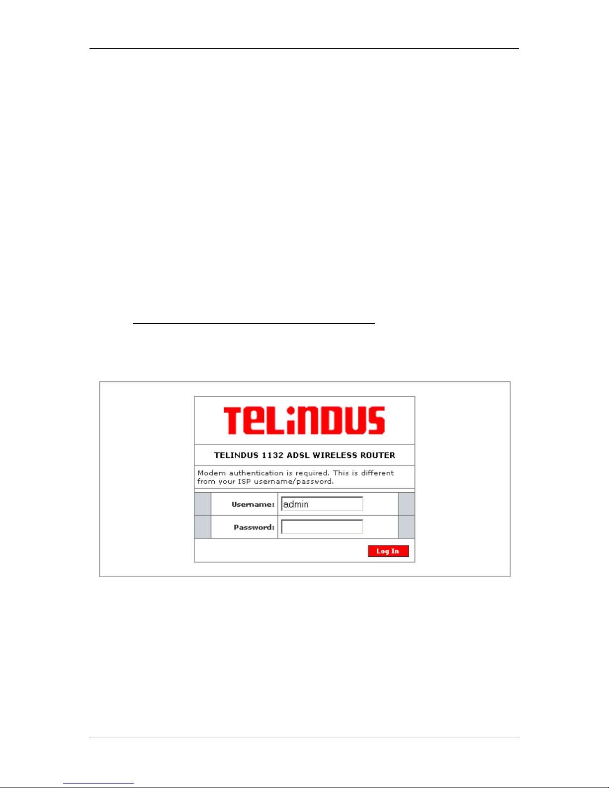
To configure your ADSL Router, open your web browser. You may get an error message at this
point; this is normal. Do not panic!. Continue following these directions. Type the default IP
address (192.168.1.1) as URL. Press the Enter key and the following screen, shown in Figure 1
will appear. The default user name is admin (case sensitive) and the password is admin (case
sensitive).
Note: Before setting up your ADSL Router, make sure you have followed the
Guide
disabled on your browser. Also if you access the ADSL Router, and instead of getting a
login screen, the browser instead displays a login redirection screen, you should check
your browser's setting, and verify that JavaScript support is enabled. Also, if you do not
get the screen shown in Figure 1, you may need to delete your temporary Internet files
(basically flush the cached web pages). If you already have a DHCP server running on your
network, you must disable one of the two DHCP servers (!!!)
4.5). Running two DHCP servers on the same network can bring down your complete
network.
. You should have your computers configured for DHCP mode and have proxies
(see DHCP settings in section
Quick Start
Version 2.0 Page 9/57 December 2004
Figure 1 (Login Screen)
TELINDUS 1132/1133 Web Interface User’s Guide
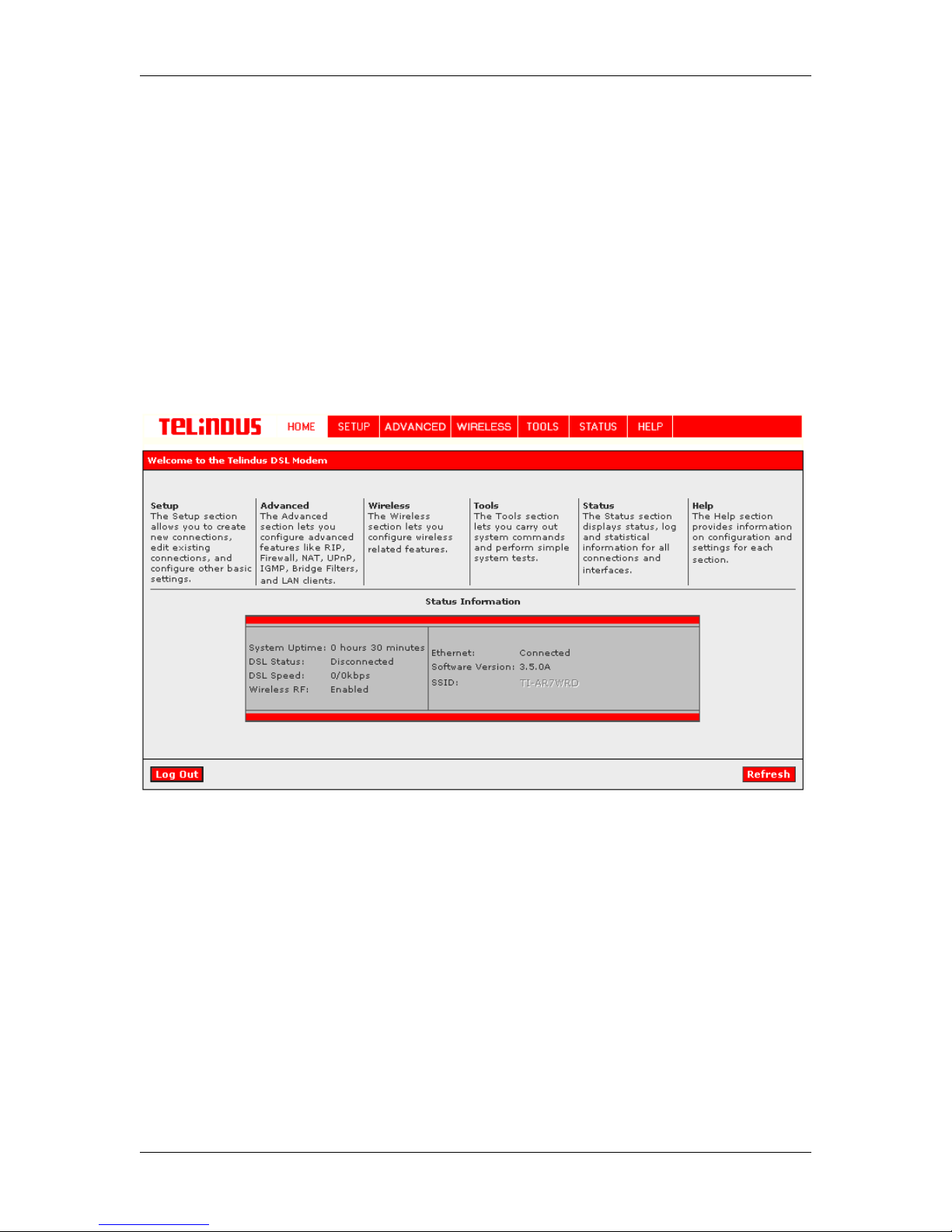
4.2 Quick Start
The first screen (Figure 2) that appears (after the log in screen) is the Home Page. This screen
gives access to the different configuration and maintenance tools on your ADSL modem:
o SETUP
o ADVANCED
o WIRELESS
o TOOLS
o STATUS
o HELP
In addition some Status Information is shown such as System Uptime, DSL Status, DSL Speed,
Wireless Status, Ethernet Status and Software Version and SSID.
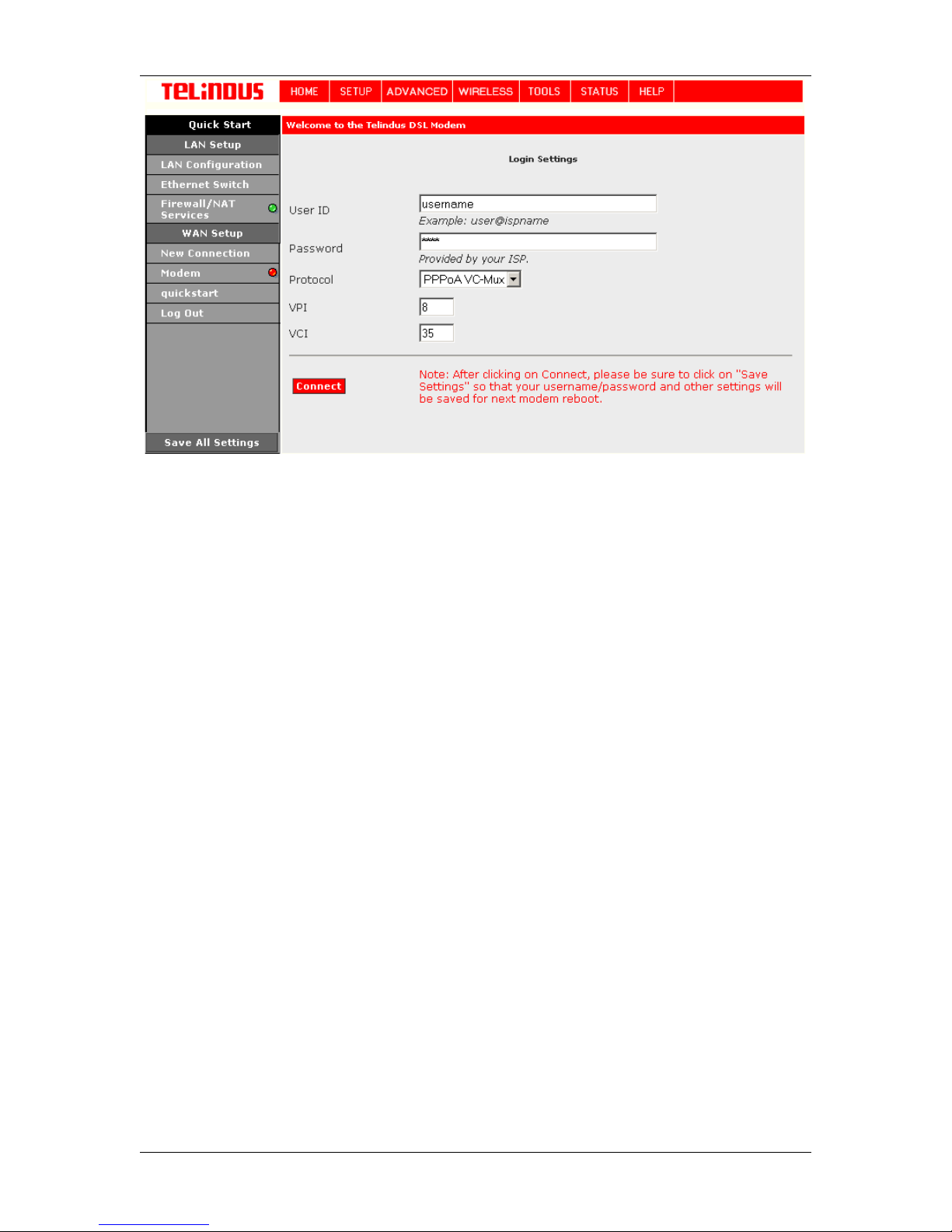
Now select SETUP and then Quick Start. This will give access to the Quick Start screen (Figure
3).
By default the ADSL Router has being configured to PPP connection and user would only need to
enter the username and password (as specified by the local ISP) to make connection to the
internet.
The Quick Start page is meant for basic users whom only require easy and seamless connectivity
to the Internet without worrying about any other advance configuration setting.
Important: After clicking on Connect, please be sure to “Save All Settings” to register the
username / password or any other changes.
Version 2.0 Page 10/57 December 2004
Figure 2 (Homepage)
TELINDUS 1132/1133 Web Interface User’s Guide
Figure 3 (Quick Start page)
Version 2.0 Page 11/57 December 2004
TELINDUS 1132/1133 Web Interface User’s Guide
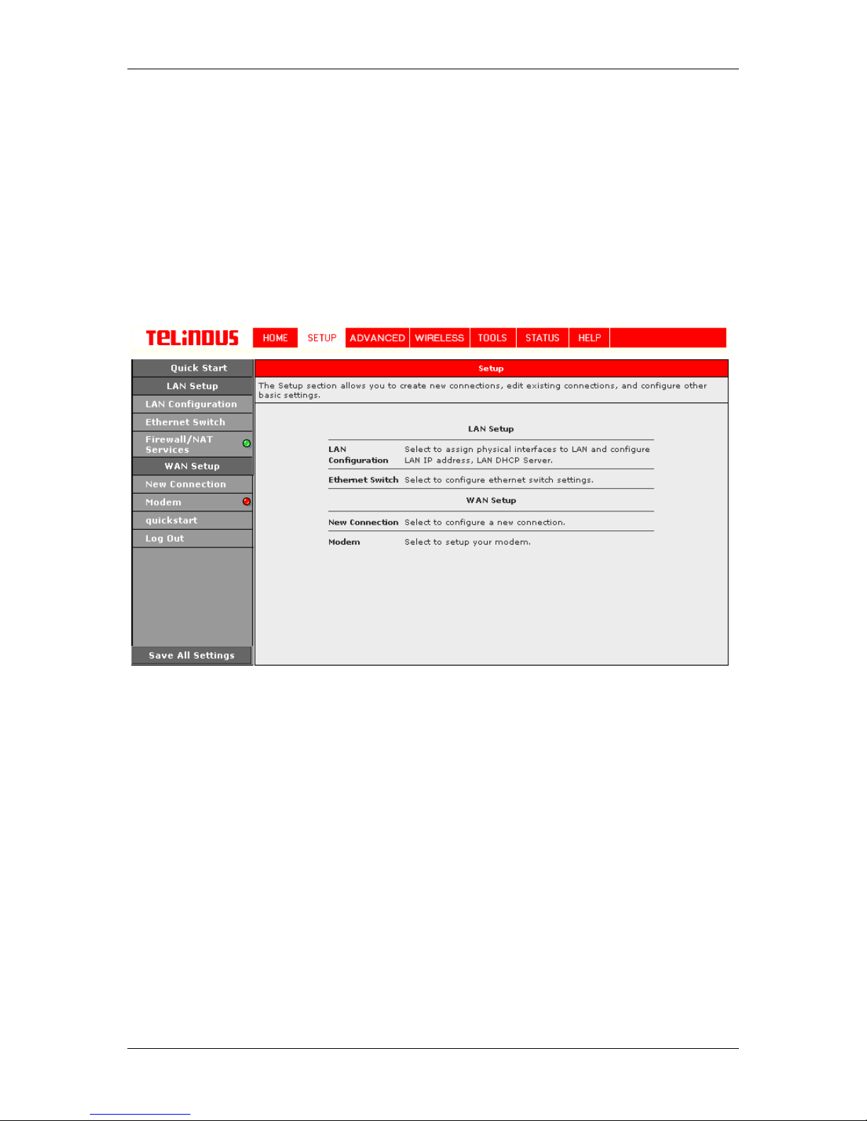
4.3 SETUP
From this screen (Figure 4) the user can setup the ADSL Router (configure the LAN and WAN
connection(s), configure the advanced configuration options within the ADSL Router (security,
routing, and filtering), access tools that are helpful for debug purposes, obtain the status of the
modem, and view the extensive online help.
To setup your ADSL Router with a basic configuration, select Setup. Figure 4 illustrates the
setup page. The page is broken into two subsections the WAN configuration and the LAN
configuration.
Before configuring the ADSL Router, there are several concepts that you should be familiar with
on how your new ADSL Router works. Please take a moment to familiarize yourself with these
concepts, as it should make the configuration much easier.
Figure 4 (Setup page)
4.3.1 Wide Area Network connection
On the other side of the ADSL Router is where your Wide Area Network (WAN) connection; also
referred to as a broadband connection. This WAN connection is usually different for every WAN
supplier. Most of the configuration you will perform will be in this area.
4.3.2 Local Area Network connection
On one side of your ADSL Router, you have your own Local Area network (LAN) connections.
This is where you plug in your local computers to the ADSL Router. The ADSL Router is normally
configured to automatically provide all the PC's on your network with Internet addresses.
Version 2.0 Page 12/57 December 2004

TELINDUS 1132/1133 Web Interface User’s Guide
4.4 Configuring the WAN
Before the gateway will pass any data between the LAN interface(s) and the WAN interface, the
WAN side of the modem must be configured. Depending upon your DSL service provider or your
ISP, you will need some (or all) of the information outlined below before you can properly
configure the WAN:
• Your DSL line VPI and VCI
• Your DSL encapsulation type and multiplexing
• Your DSL training mode (default is MMODE)
• For PPPoA or PPPoE users, you also need these values from your ISP:
• Your username and password
• For RFC 1483 users, you may need these values from your ISP:
• Your DSL fixed Internet IP address
• Your Subnet Mask
• Your Default Gateway
• Your primary DNS IP address
Since multiple users can use the ADSL Router, the ADSL router can simultaneously support
multiple connection types; hence, the user must set up different profiles for each connection. The
ADSL Router supports the following protocols:
• DHCP
• RFC2364 / PPPoA
• RFC2516 / PPPoE
• Static
• Bridged
• RFC1577 / CLIP
.
4.4.1 New Connection
A new connection is basically a virtual connection. Your ADSL Router can support up to 8
different (unique) virtual connections. If you have multiple different virtual connections, you may
need to utilize the static and dynamic routing capabilities of the modem to pass data correctly.
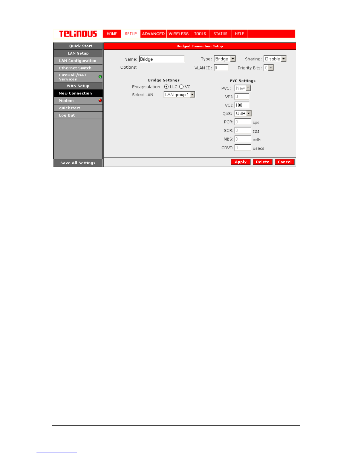
4.4.1.1 Bridged gateway profile and Connection
A pure bridged connection does not assign and IP address to the WAN interface. NAT and
firewall rules are not enabled. This connection method makes the ADSL Router act as a hub,
and just passes packets across the WAN interface to the LAN interface.
To configure the ADSL Router as a bridge, click on Setup and then click on New Connection. The
default PPPoE connection setup is displayed. At the Type field select Bridge and the Bridge
connection setup page is displayed (see Figure 5). Give your Bridge connection a unique name;
the name must not have spaces and cannot begin with numbers. In this case the unique name is
called Bridge. Select the encapsulation type (LLC or VC); if you are not sure just use the default
mode. Select the VPI and VCI settings; your DSL service provider or your ISP will supply these;
in this case the DSL service provider is using 0,100. Also select the ATM Quality of Service
(QoS); leave the default value if you are unsure or the ISP did not provide this information.
Version 2.0 Page 13/57 December 2004
TELINDUS 1132/1133 Web Interface User’s Guide
Figure 5 (Bridge Connection Setup)
To complete the connection you must now click the Apply button. The Apply button will
temporarily save this connection. To make the change permanent, you need to click on Save All
Settings. At the System Commands page under the TOOLS, click on Save All.
4.4.1.2 PPPoA Connection Setup
PPPoA is also known as RFC 2364. It is a method of encapsulating PPP packets over ATM cells
which are carried over the DSL line. PPP or Point-to-Point protocol is a method of establishing a
network connection / session between network hosts. It usually provides a mechanism of
authenticating users. LLC and VC are two different methods of encapsulating the PPP packet.
Contact your ISP to make sure which encapsulation is being supported.
By selecting PPPoA, you are forcing your ADSL Router to terminate the PPPoA connection. The
advantage is that the PPPoA termination is done within the ADSL Router and not on your PC; this
frees up your PC resources and allows multiple users to utilize the PPPoA connection.
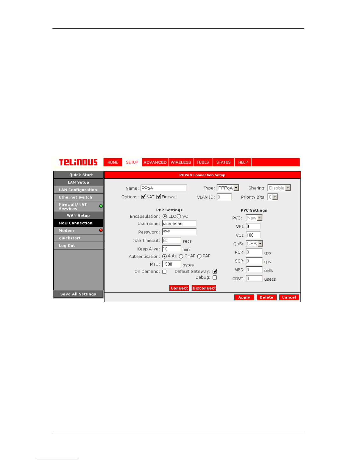
To configure the gateway for PPPoA, click on Setup and then click on New Connection. The
default PPPoE connection setup is displayed. At the Type field select PPPoA and the PPPoA
connection setup page is displayed; Figure 6 illustrates a typical PPPoA configuration. Give your
PPPoA connection a unique name; the name must not have spaces and cannot begin with
numbers. In this case the unique name is called PPPoA1. Select the encapsulation type (LLC or
VC); if you are not sure just use the default mode. Select the VPI and VCI settings; your DSL
service provider or your ISP will supply these; in this case the DSL service provider is using
0,100. Also select the ATM Quality of Service (QoS); leave the default value if you are unsure or
the ISP did not provide this information.
Following is a description of the different options:
Version 2.0 Page 14/57 December 2004
TELINDUS 1132/1133 Web Interface User’s Guide
a. Username: The username for the PPPoA access; this is provided by your DSL
service provider or your ISP.
b. Password: The password for the PPPoA access; this is provided by your DSL service
provider or your ISP.
c. On-Demand: Enables on-demand mode. The connection will disconnect if no activity
is detected after the specified idle timeout value.
d. Idle Timeout: Specifies that PPPoA connection should disconnect if the link has no
activity detected for n seconds. This field is used in conjunction with the On-Demand
feature. To ensure that the link is always active, enter a 0 in this field.
e. Keep Alive: When on-demand option is not enable, this value specifies the time to
wait without being connected to your provider before terminating the connection. To
ensure that the link is always active, enter a 0 in this field.
f. Default Gateway: Specify this connection as the default-route.
g. MTU: Maximum Transmission Unit the DSL connection can receive. It is a negotiated
value that asks the provider to send packets of no more than n bytes. The maximum
specified value is 1500 although some DSL/ISP providers require a larger value. The
minimum MTU value is 128.
To complete the connection you must now click the Apply button. The Apply button will
temporarily save this connection. To make the change permanent, you need to click on Save All
Settings. At the System Commands page under the TOOLS, click on Save All.
4.4.1.3 PPPoE Connection Setup
PPPoE is also known as RFC 2516. It is a method of encapsulating PPP packets over Ethernet.
PPP or Point-to-Point protocol is a method of establishing a network connection/session between
network hosts. It also provides a mechanism of authenticating users.
Version 2.0 Page 15/57 December 2004
Figure 6 (PPPoA Connection Setup)

TELINDUS 1132/1133 Web Interface User’s Guide
To configure the gateway for PPPoE, click on Setup and then click on New Connection. The
default PPPoE connection setup is displayed. At the Type field select PPPoE and the PPPoE
connection setup page is displayed; Figure 7 illustrates a typical PPPoE configuration. Give your
PPPoE connection a unique name; the name must not have spaces and cannot begin with
numbers. In this case the unique name is called PPPoE1. Select the encapsulation type (LLC or
VC); if you are not sure just use the default mode. Select the VPI and VCI settings; your DSL
service provider or your ISP will supply these; in this case the DSL service provider is using
0,100. Also select the ATM Quality of Service (QoS); leave the default value if you are unsure or
the ISP did not provide this information.
Following is a description of the different options:
h. Username: The username for the PPPoE access; this is provided by your DSL
service provider or your ISP.
i. Pas sword: The password for the PPPoE access; this is provided by your DSL service
provider or your ISP.
j. On-Demand: Enables on-demand mode. The connection will disconnect if no activity
is detected after the specified idle timeout value.
k. Idle Timeout: Specifies that PPPoE connection should disconnect if the link has no
activity detected for n seconds. This field is used in conjunction with the On-Demand
feature. To ensure that the link is always active, enter a 0 in this field.
l. Keep Alive: When on-demand option is not enable, this value specifies the time to
wait without being connected to your provider before terminating the connection. To
ensure that the link is always active, enter a 0 in this field.
m. Default Gateway: Specify this connection as the default-route.
n. MTU: Maximum Transmission Unit the DSL connection can receive. It is a negotiated
value that asks the provider to send packets of no more than n bytes. The maximum
specified value is 1500 although some DSL/ISP providers require a larger value. The
minimum MTU value is 128.
o. Enforce MTU: Check this box if you experience problems accessing the Internet over
a PPPoE connection. This feature will force all TCP traffic to conform with PPP MRU
by changing TCP Maximum Segment Size to PPP MRU.
p.
Version 2.0 Page 16/57 December 2004
Figure 7 (PPPoE Connection Setup)
TELINDUS 1132/1133 Web Interface User’s Guide
To complete the connection you must now click the Apply button. The Apply button will
temporarily save this connection. To make the change permanent, you need to click on Save All
Settings. At the System Commands page under the TOOLS, click on Save All.
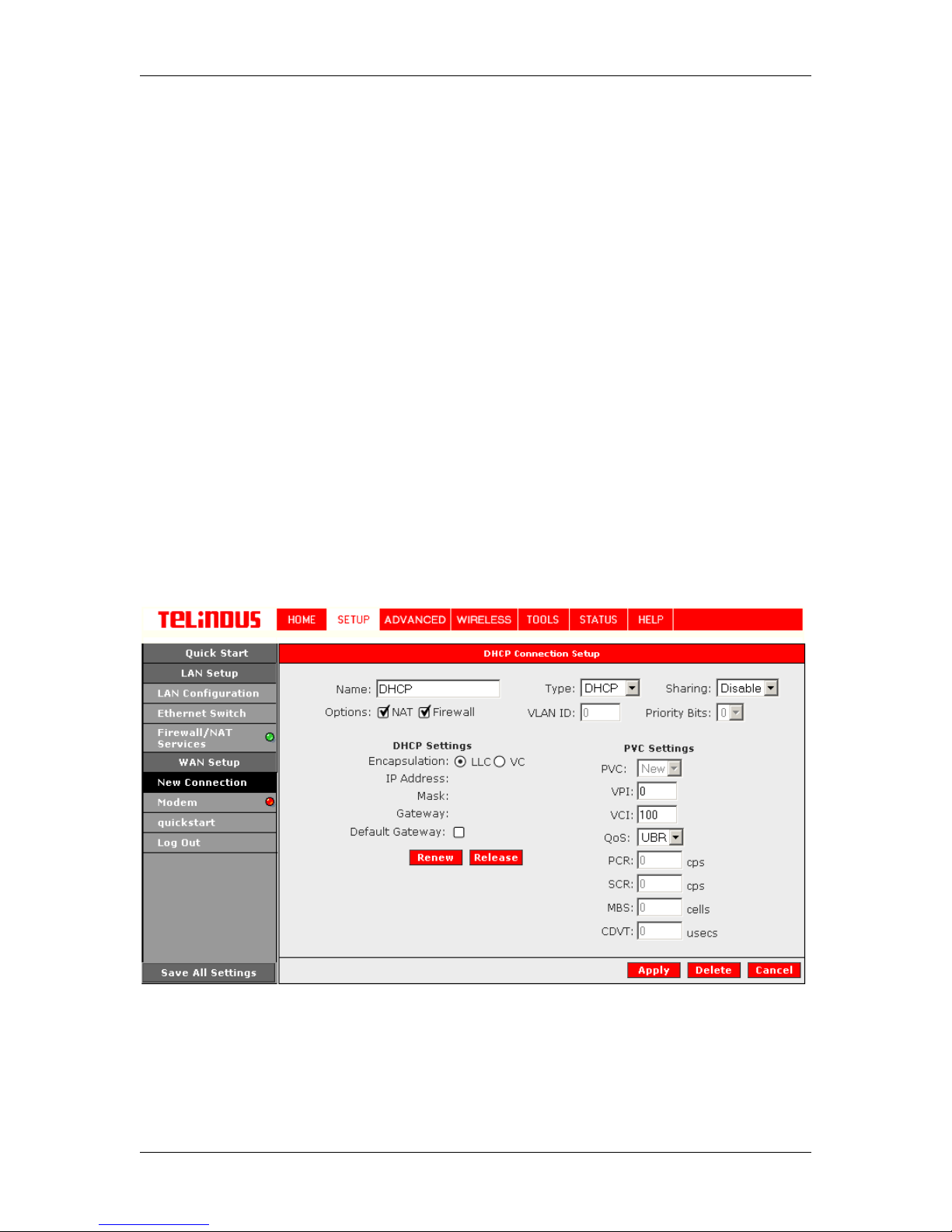
4.4.1.4 DHCP Connection Setup
Dynamic Host Configuration Protocol (DHCP) allows the ADSL Router to automatically obtain the
IP address from the server. This option is commonly used in situations where IP is dynamically
assigned and is not known prior to assignment.
To configure the ADSL Router for a DHCP connection, click on Setup and then click on New
Connection. The default DHCP connection setup is displayed. At the Type field select DHCP
and the DHCP connection setup page is displayed; Figure 8 illustrates a typical DHCP
configuration. Give your DHCP connection a unique name; the name must not have spaces and
cannot begin with numbers. In this case the unique name is called DHCP1. Select the
encapsulation type (LLC or VC); if you are not sure just use the default mode. Select the VPI and
VCI settings; your DSL service provider or your ISP will supply these; in this case the DSL service
provider is using 0,100. Also select the ATM Quality of Service (QoS); leave the default value if
you are unsure or the ISP did not provide this information.
If your DSL line is connected and your DSL/IPS provider is supporting DHCP, you can click the
renew button and the gateway will retrieve an IP address, Subnet mask, and Gateway address.
At anytime, you can renew the DHCP address by clicking on the renew button; in most cases you
will never have to use this button.
To complete the connection you must now click the Apply button. The Apply button will
temporarily save this connection. To make the change permanent, you need to click on Save All
Settings. At the System Commands page under the TOOLS, click on Save All.
Version 2.0 Page 17/57 December 2004
Figure 8 (DHCP Connection Setup)
TELINDUS 1132/1133 Web Interface User’s Guide
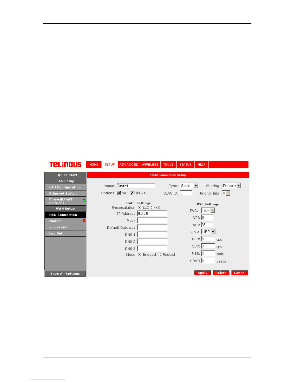
4.4.1.5 Static Connection Setup
Static is used whenever a known static IP is assigned. The accompanying information such as
the Subnet mask and the gateway should also be specified. Up to three Domain Name Server
(DNS) addresses can also be specified. These servers would enable you to have access to other
web servers. Valid IP addresses range is from 0.0.0.0 to 255.255.255.255.
To configure the ADSL Router for a Static connection, click on Setup and then click on New
Connection. The default Static connection setup is displayed. At the Type field select Static and
the Static connection setup page is displayed; Figure 9 illustrates a typical Static configuration.
Give your Static connection a unique name; the name must not have spaces and cannot begin
with numbers. In this case the unique name is called Static1. Select the encapsulation type (LLC
or VC); if you are not sure just use the default mode. Select the VPI and VCI settings; your DSL
service provider or your ISP will supply these; in this case the DSL service provider is using 0,35.
Also select the ATM Quality of Service (QoS); leave the default value if you are unsure or the ISP
did not provide this information. You can also enable Network Address Translation (NAT) and
the Firewall options. If you are unsure, leave these in the default mode.
Based upon the information your DSL/ISP provided, enter your assigned IP address, Subnet
Mask, Default Gateway (if provided), and Domain Name Services (DNS) values (if provided). For
the static configuration, you can also select a bridge connection or a routed connection. Since
static IP address is typically used to host WEB servers, you may want to use a bridge connection.
To complete the connection you must now click the Apply button. The Apply button will
temporarily save this connection. To make the change permanent, you need to click on Save All
Settings. At the System Commands page under the TOOLS, click on Save All.
4.4.1.6 Classical IP over ATM (CLIP, defined in RFC1577) Connection Setup
The Classical IP over ATM (CLIP) support provides the ability to transmit IP packets over an ATM
network, CLIP support will encapsulate IP in an AAL5 Packet Data Unit (PDU) frame using
Version 2.0 Page 18/57 December 2004
Figure 9 (Static Connection Setup)
 Loading...