

Page 1
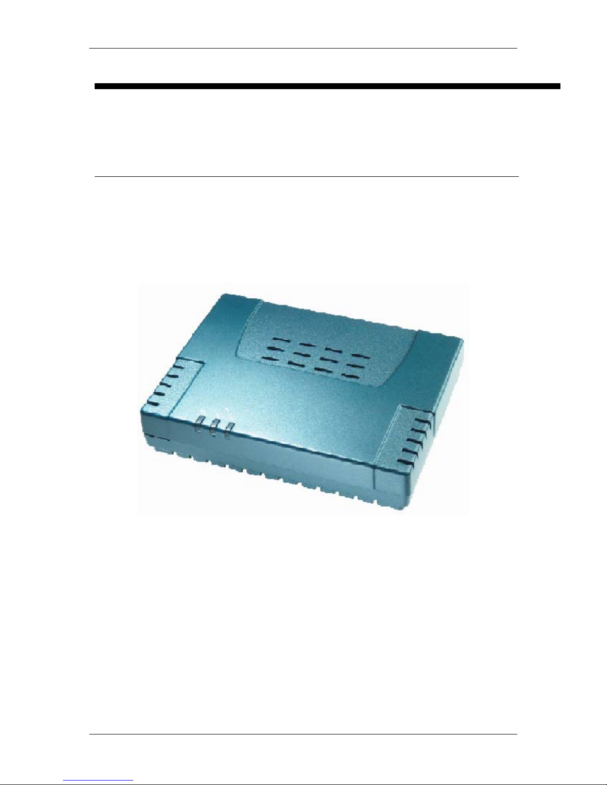
TELINDUS 1130/1131 Web Interface User’s Guide
Web Interface User’s Guide
TELINDUS 1 130/1 131 ADSL ROUTER/BRIDGE
Version 2.0 Page 1/52 October 2004
Page 2

TELINDUS TELINDUS 1130/1131 Web Interface User’s Guide
Contents
1. INTRODUCTION...................................................................................................... 4
1.1 FEATURES
........................................................................................................... 4
2. YOUR GATEWAY AT A GLANCE....................................................................... 6
2.1 P
2.2 LED DESCRIPTION
ORTS AND BUTTONS
.............................................................................................. 6
......................................................................................... 6
3. INSTALLING YOUR ADSL ROUTER.................................................................. 7
4. SETTING UP YOUR ADSL ROUTER.................................................................. 8
4.1 LOG INTO YOUR ADSL ROUTER
4.2 QUICK START
4.3 SETUP
4.3.1
4.3.2
Wide Area Network connection............................................................ 11
Local Area Network connection...........................................................11
4.4 CONFIGURING THE WAN
4.4.1
4.4.2
4.4.3
New Connection.....................................................................................12
Modify an Existing Connection ............................................................. 19
Modem setup.......................................................................................... 19
4.5 CONFIGURING THE LAN
4.5.1
4.5.2
Configure a LAN group.......................................................................... 20
Firewall/NAT Services........................................................................... 23
...................................................................................................... 9
............................................................................................................. 11
.................................................................................. 12
.................................................................................... 19
4.6 ADVANCED (FOR ADVANCED USERS ONLY)
4.6.1
4.6.2
4.6.3
4.6.4
4.6.5
4.6.6
4.6.7
4.6.8
4.6.9
UPnP........................................................................................................ 24
SNTP........................................................................................................ 25
SNMP....................................................................................................... 26
DNS Proxy............................................................................................... 27
Dynamic DNS Client.............................................................................. 28
IP QoS...................................................................................................... 29
Port Forwarding...................................................................................... 32
IP Filters................................................................................................... 33
LAN Clients ............................................................................................. 34
........................................................................ 8
.................................................. 24
4.6.10 LAN Isolation ........................................................................................... 35
4.6.11 Bridge Filters........................................................................................... 35
4.6.12 Web Filters.............................................................................................. 37
4.6.13 URL Filter................................................................................................. 38
4.6.14 Multicast................................................................................................... 39
4.6.15 Static Routing.......................................................................................... 40
4.6.16 Dynamic Routing.................................................................................... 41
4.6.17 Show Routes........................................................................................... 42
4.6.18 Access Control........................................................................................ 43
4.7 TOOLS
4.7.1
4.7.2
............................................................................................................. 45
System Commands................................................................................ 45
Remote Log............................................................................................. 45
Version 2.0 Page 2/52 December 2004
Page 3

TELINDUS TELINDUS 1130/1131 Web Interface User’s Guide
4.7.3
4.7.4
4.7.5
4.7.6
4.8 STATUS
4.8.1
4.8.2
4.8.3
4.8.4
4.8.5
4.8.6
User Management.................................................................................. 45
Update Firmware.................................................................................... 45
Ping Test.................................................................................................. 46
Modem Test............................................................................................ 47
........................................................................................................... 48
Network Statistics................................................................................... 48
Connection Status.................................................................................. 48
DHCP Clients.......................................................................................... 48
Modem Status......................................................................................... 48
Product Information................................................................................ 48
System Log............................................................................................. 49
5. APPENDIX A: TROUBLESHOOTING............................................................... 50
5.1 THE ADSL ROUTER IS NOT FUNCTIONAL
5.2 I CAN’T CONNECT TO THE ADSL ROUTER.
5.3 THE DSL LINK LED CONTINUES TO BLINK BUT DOES NOT GO SOLID
5.4 THE DSL LINK LED IS ALWAYS OFF
......................................................... 50
...................................................... 50
.............. 51
................................................................ 51
6. ADSL ROUTER TERMS....................................................................................... 52
Version 2.0 Page 3/52 December 2004
Page 4

TELINDUS TELINDUS 1130/1131 Web Interface User’s Guide
1. Introduction
The TELINDUS 1130/1131 is a cost-efficient high-speed ADS L bridge/router for SOHO or SME
users. This rich-featured product is specifically designed to connect to the Internet and directly
connect to your local area net work v ia high speed 10/ 100 Mbps Ethernet . The ADS L Router has
a full NAT firewall and DMZ services to bloc k unwanted users from accessing your network .
For game users, the ADSL Rout e r ha d alre ad y pre -c onfig ure d f or s ev eral l ow l a t ency gam e p ort s .
Just click on the game you are playing on line and the rest is done for you.
The ADSL Router is fully compatible with all PCs; as long as the PC supports an Ethernet
interface and is running a TCP/IP protocol stack, your PC can have high-speed WAN access.
So, plug in the ADSL Router (refer to Quick Start guide), configure it (per your ISP’s
requirements) and enjoy the fast Internet access like never before.
1.1 Features
ADSL/ATM Support
•
ANSI T1.413 issue 2, ITU-T G.992.1 (G .dmt) and G.992.2 (G.lite) compliant
•
ADSL2, ADSL2+, RE-ADSL compliant
•
Rate Adaptive modem at 32 Kbps steps
•
Dynamic Adaptive Equalisation to impro ve Carrier’s service area
•
Bridge Tap Mitigation support
•
ATM Layer with Traffic shaping QoS Support (UBR, CBR, VBR-rt, VBR-nrt)
•
AAL ATM Attributes - AAL5
•
Multiple PVC up to 8 support (Bridge Su pp o rt)
•
Spectral compatibility with POTS
•
F5 OAM Loopback/Send and Receiv e
Encapsulation Support
•
RFC2684 Bridge and Routed LLC and VC Mux support
•
RFC2364 PPPoA Client support
•
RFC2516 PPPoE Client support
•
RFC2225/RFC1577 Classical IP Supp o rt (CLIP)
•
Transparent Bridge Support
Network Support
•
Static IP, Dynamic RIP routing support
•
IP/TCP/UDP/ICMP/ARP/RARP Application Support
•
Network Address Translat ion (NAT)
•
Port Mapping/Forwardin g
•
Easy setup of Port Forwarding rul es for popular Games/Application
•
NAT Application Level Gateway for popular applications
•
DHCP Server/Relay/client
•
DNS Relay Agent
•
DMZ support
•
Single Session IP Sec and PPTP /L2TP VPN pass through support
•
PPP Always on with configurable t i meo ut
•
PPP Dial on Demand
•
Universal Plug and Play Support
Version 2.0 Page 4/52 December 2004
Page 5

TELINDUS TELINDUS 1130/1131 Web Interface User’s Guide
Management Support
•
Web Based HTTP management GUI
•
TFTP/FTP Support for Firmware Upgrade
•
Web Based Firmware Upgr ade (Local)
•
Soft Factory Reset Button via Web G UI
•
Diagnostic Test (DSL, OAM, Network, Ping Test)
•
Telnet/CLI (Read Only)
•
Syslog Support
Security Support
•
NAT for basic Firewall support
•
Packet Filtering Firewall Supp ort
•
Stateful Packet Inspection Support
•
IP Filters
•
Bridge Filters (up to 20 rules)
•
Protection against Denial o f Service attacks
•
Password Authentication to Mod em
External Connectors:
•
1 x RJ-11 Telephone socket for ADSL line
•
1 x RJ45 for 10/100Base-T Ethern et (MDI-X)
•
1 x USB 1.1 Type B
•
1 x DC Jack for Power Input
Version 2.0 Page 5/52 December 2004
Page 6

TELINDUS TELINDUS 1130/1131 Web Interface User’s Guide
2. Your gateway at a glance
The ADSL Ethernet & USB Combo has different ports and LEDs. Let ’ s take a look at the different
options. Depending upon your model, it may have some or all of the features listed below
2.1 Ports and buttons
Reset and Restore to Factory Defaults:
to its factory default configuration by resetting the ADSL Router. You may need to place the
ADSL Router into its factory defaults if the configuration is changed, if you loose the ability to
interface to the ADS L Router via the web interf ace or following a soft ware upgrad e. To res et the
ADSL Router, simply pres s the reset button for about ~ 10 s econds. The ADSL Router will be
reset to its factory defaults and after about 30 ~ 40 seconds the ADSL Router will become
operational again. If the ADSL Router has no Reset button (some models), use the System
Commands screen under TOOLS.
LAN (local area network) port(s):
switch, or routers. The TELINDUS 1130/1131 comes with a singl e LAN connection. Depending
on the connection, you may need a cross-over cable or a straight-through cable.
Power
The require power voltage is 9 volts DC.
USB (universal serial port):
Window’s based PCs via an RNDIS driv er (included in the software).
DSL port:
is where you connect the power. Make sure to observe the proper power requirements.
connects to a PC’s USB port. The ADSL Router only supports
This is the WAN interface that connects directly to your phone line.
The Restore Defaults f eature will set t he ADSL Rout er
connect to Ethernet network devices, such as a PC, hub,
2.2 LED description
1. PWR/POWER
Lights up
when power is supplied to the ADSL Router.
2. ETH/ACT
Lights up
Ethernet Card.
Flickers
when the Ethernet cable is properly connected from your ADSL Router to the
when the ADSL is transmitting/receiving data.
3. USB
Lights up
Flickers
when the USB connection is established.
when the ADSL is transmitting/receiving dat a
4. DSL
Lights up
Flickers
Service Provider.
when the DSL connection is est ablished.
when the ADSL Router is trying to establish a connection with the ADSL
5. PPP/Internet
Lights up
when the PPP connection is establis hed.
Version 2.0 Page 6/52 December 2004
Page 7
TELINDUS TELINDUS 1130/1131 Web Interface User’s Guide
3. Installing your ADSL Router
1. Locate an optimum location for the ADSL Router.
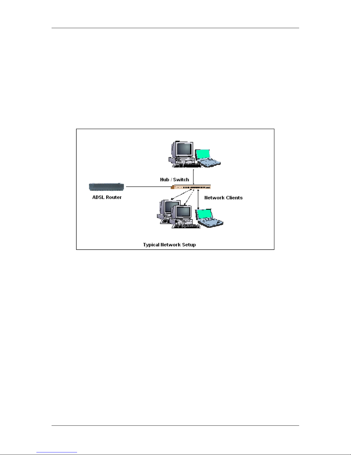
2. For connections to the Ethe rnet and DSL interfaces, please refer to the
3. Connect the AC Power Adapter. Depending upon the type of net wo rk, you may want to put
the power supply on an uninterrupt ible supply. Only use the power adapter s up plied with the
ADSL Router. A different adapter may dama ge the product.
Now that the hardware installat i on is complete, proceed to
Router
Chapter 4: Setting up your ADSL
Quick Start Guide
.
Version 2.0 Page 7/52 December 2004
Page 8
TELINDUS TELINDUS 1130/1131 Web Interface User’s Guide
4. Setting up your ADSL Router
This section will guide you through your ADSL Router’s configuration. The ADSL Router is
shipped with a standard PPP conf igu ration.
4.1 Log into your ADSL Router
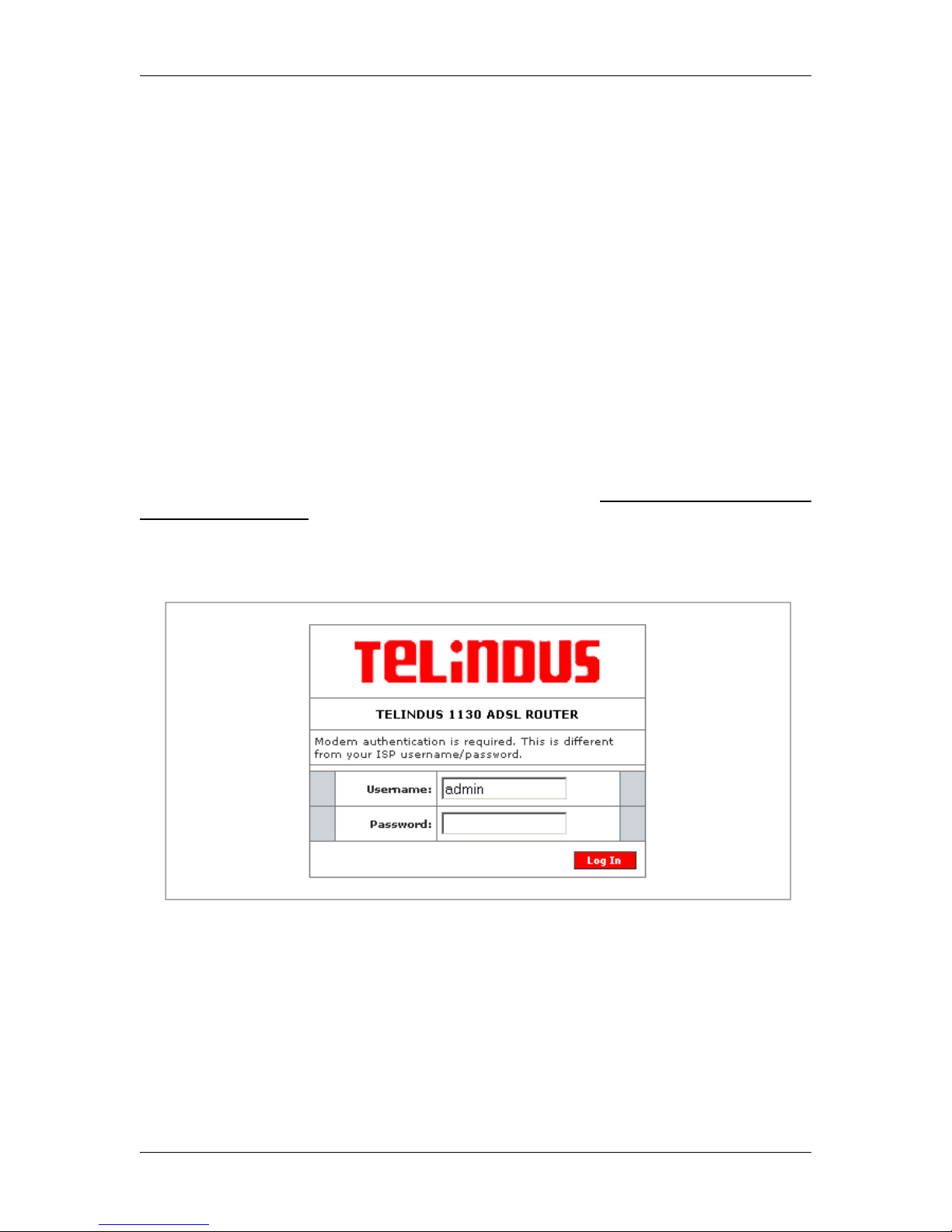
To configure your ADSL Rout er, open your we b browser. You ma y get an error mess age at this
point; this is normal. Do not panic!. Continue following these directions. Type the default IP
address (
will appear. The default user name is
sensitive).
Note: Before setting up your ADSL Router, make sure you have followed the Quick Start
guide. You should have your computers configured for DHCP mode (Automatically obtain
IP Address) and have proxies disabled on your browser. Also if you access the ADSL
Router, and instead of getting a login screen, the browser instead displays a login
redirection screen, you should check your browser's setting, and verify that JavaScript
support is enabled. Also, if you do not get the screen shown in Figure 1, you may need to
delete your temporary Internet files (basically flush the cached web pages).
If you already have a DHCP server running on your network, you must disable one of the
two DHCP servers (!!!) (see DHCP settings in section 4.5). Running two DHCP servers on
the same network can bring down your complete network.
192.168.1.1
) as URL. Press the
Enter
key and the following sc reen, shown in Figure 1
admin
(case sensitive) and the pas sword is
admin
(case
Version 2.0 Page 8/52 December 2004
Figure 1 (Log-in screen)
Page 9

TELINDUS TELINDUS 1130/1131 Web Interface User’s Guide
4.2 Quick Start
The first screen (Figure 2) that appears (after the log in screen) is the Home Page. This screen
gives access to the different conf igu ration and maintenance tools on your ADSL modem:
- SETUP
- ADVANCED
- TOOLS
- STATUS
- HELP
In addition some Status Inform ation is shown such as System Upt ime, DSL Status, DSL Speed,
Ethernet Status and Software Version.
Figure 2 (Homepage)
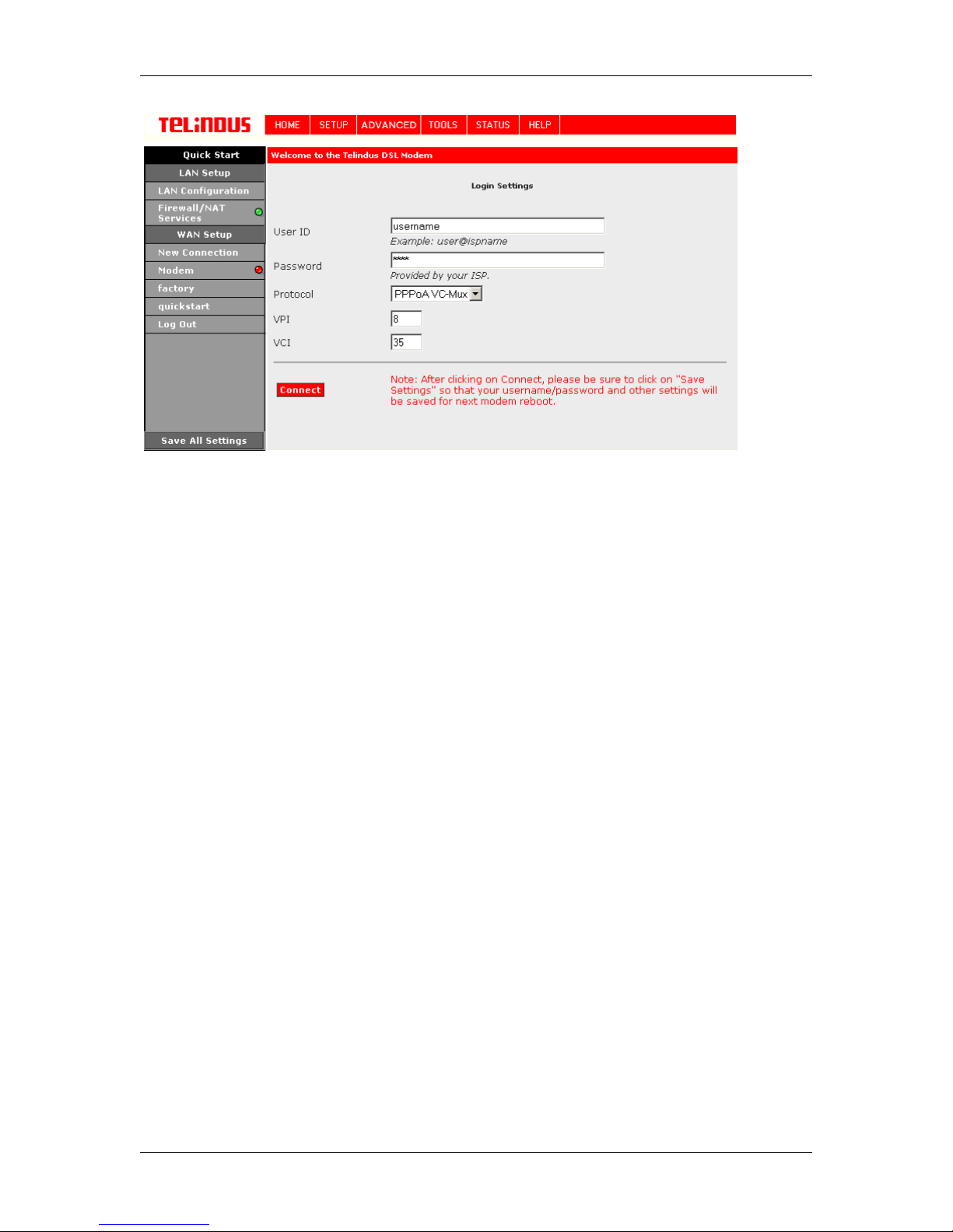
Now select SETUP and then Quick Start. This will give access to the Quick Start screen (Figure
3).
By default the ADSL Router has being configured to PPP connection and user would only need to
enter the username and password (as specified by the local ISP) to make connection to the
internet.
The Quick Start page is meant for b asi c us ers wh om onl y req ui re e asy and s eam less conn ec ti v ity
to the Internet without worrying about any other advance conf iguration setting.
Important: After clicking on Connect, please be sure to “Save All Settings” to register the
username / password or any oth er changes.
Version 2.0 Page 9/52 December 2004
Page 10
TELINDUS TELINDUS 1130/1131 Web Interface User’s Guide
Figure 3 (Quick Start page)
Version 2.0 Page 10/52 December 2004
Page 11
TELINDUS TELINDUS 1130/1131 Web Interface User’s Guide
4.3 SETUP
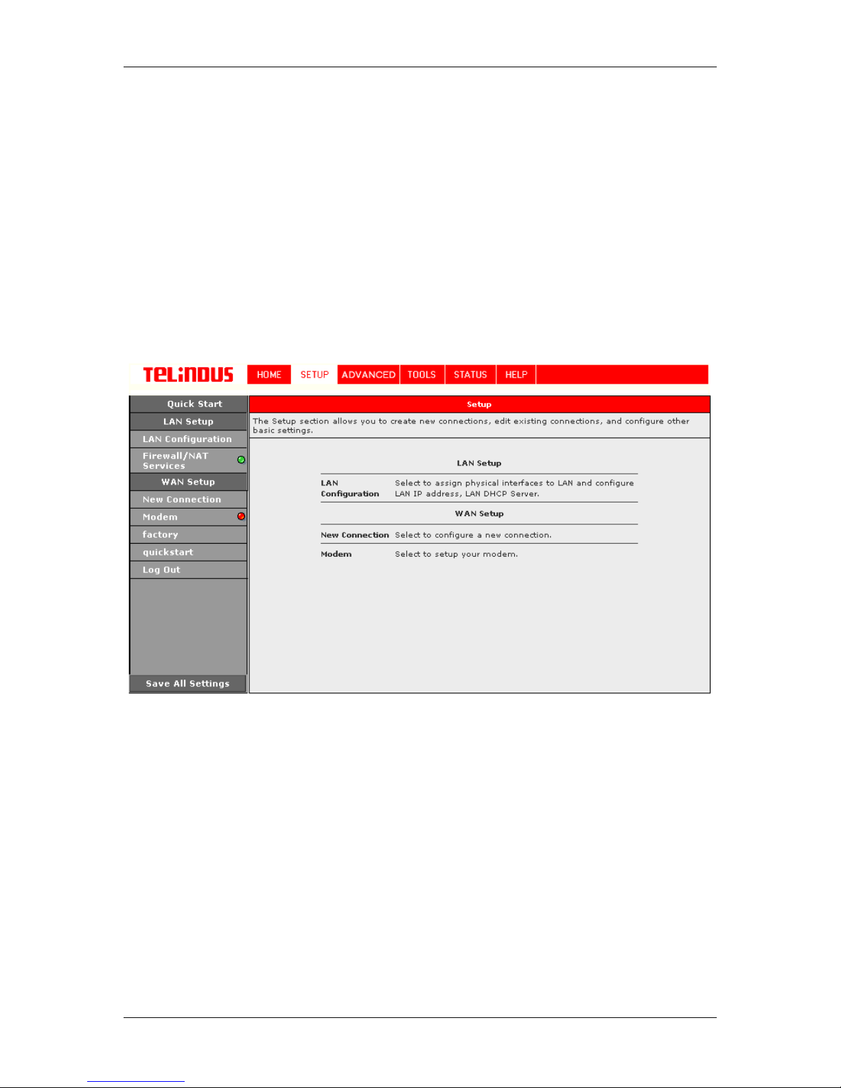
From this screen (Figure 4) t he user can setup the ADSL Route r (configure the LAN and WAN
connection(s), configure the advanced configuration options within the ADSL Router (security,
routing, and filtering), acc ess tools that are helpful for debug purposes , obtain the status of the
modem, and view the extensive online help.
To setup your ADSL Router with a basic configuration, select Setup. Figure 4 illustrates the
setup page. The page is broken into two subsections the WAN configur ation and the LAN
configuration.
Before configuring the ADSL Router, there are several concepts that you should be familiar with
on how your new ADSL Router works. Please take a moment to familiarize yourself with these
concepts, as it should mak e the configuration much easier.
4.3.1 Wide Area Network connection
On the other side of the ADSL R outer is where your Wide Area Net work (WAN) connecti on; also
referred to as a broadba nd connection. This WAN c onnection is usually diff erent for every WAN
supplier. Most of the configuration you will perfo rm will be in this area.
4.3.2 Local Area Network connection
On one side of your ADSL Router, you have your own Local Area network (LAN) c onnections.
This is where you plug in your local comput ers to the A DSL Rout er. The ADS L Router is norm ally
configured to automatically provide all the PC's on your network with Internet addresses.
Version 2.0 Page 11/52 December 2004
Figure 4 (Setup page)
Page 12

TELINDUS TELINDUS 1130/1131 Web Interface User’s Guide
4.4 Configuring the WAN
Before the gateway will pass any data between the LAN interface(s) and the WAN interface, the
WAN side of the modem must be configured. Depending upon your DSL service provider or your
ISP, you will need some (or all) of the information outlined below before you can properly
configure the WAN:
•
Your DSL line VPI and VCI
•
Your DSL encapsulation type and mult iplexing
•
Your DSL training mode (default is MMODE)
•
PPPoA
For
•
Your username and pas sword
•
RFC 1483
For
•
Your DSL fixed Internet I P address
•
Your Subnet Mask
•
Your Default Gateway
•
Your primary DNS IP address
Since multiple users can use the ADSL Router, the ADSL router can simultaneously support
multiple connection types; henc e, t he us er mus t s et up diff erent pr of iles for each connection. The
ADSL Router supports the following protocols:
•
DHCP
•
RFC2364 / PPPoA
•
RFC2516 / PPPoE
•
Static
•
Bridged
•
RFC1577 / CLIP
.
4.4.1 New Connection
PPPoE
or
users, you may need these values f r om your ISP:
users, you also need these values from your ISP:
A new connection is basically a virtual connection. Your ADSL Router can support up to 8
different (unique) virt ual connections. If you h ave multiple different vi rtual connections, you may
need to utilize the static and dynamic routing capabi lities of the modem to pass data correctly.
4.4.1.1 Bridged gateway profile and Connection
A pure bridged connection does not assign and IP address to the WAN interface. NAT and
firewall rules are not enabled. This connection method mak es the ADSL Router act as a hub,
and just passes packets acros s the WAN interface to the LAN interface.
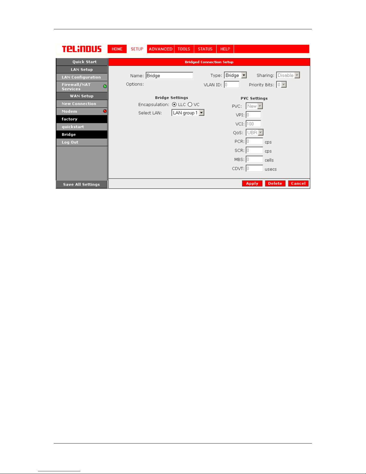
To configure the ADSL Router as a bridge, click on Setup and then click on New Connection. The
default PPPoE connection setup is displayed. At the Type field select Bridge and the Bridge
connection setup page is displayed (see Figur e 5). Give your Bri dge connect ion a unique name;
the name must not h av e spac es and c ann ot be gi n wi t h n umbe rs . I n this c as e t he u ni que na me is
called Bridge. Select the encapsulat ion type (LLC o r VC); if you are n ot sure just us e the default
mode. Select the VPI and VCI settings; your DSL service provider or your ISP will supply these;
in this case the DSL service provider is using 0,100. Also select the ATM Quality of Service
(QoS); leave the default value if you are unsure or the ISP did not provide this information.
Version 2.0 Page 12/52 December 2004
Page 13
TELINDUS TELINDUS 1130/1131 Web Interface User’s Guide
Figure 5 (Bridge Connection Setup)
To complete the connection you must now click the Apply button. The Apply button will
temporarily save this connection. To make the change permanent, you ne ed to click on
Settings
. At the System Commands page under the TOOLS, c lick on
Save All
.
Save All
4.4.1.2 PPPoA Connection Setup
PPPoA is also known as RFC 2364. It is a meth od of enca psulating P PP pack ets over AT M cells
which are carried over the DS L line. PPP or Point-to-Point protocol is a method of est ablishing a
network connection / session between network hosts. It usually provides a mechanism of
authenticating users . LLC and VC are two different met hods of encapsulating the PPP pack et.
Contact your ISP to make sure which enc apsulation is being supported.
By selecting PPPoA, you are forci ng your A DSL Ro uter t o termina te the P PPoA con nection. The
advantage is that the PPPoA termination is done within the ADSL Router and not on your PC; this
frees up your PC resources and allows multiple users to utilize the PPPoA connection.
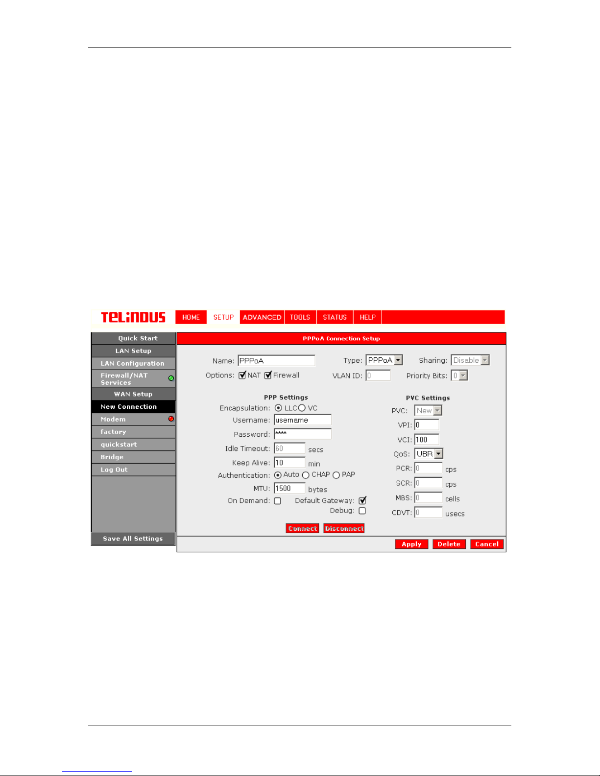
To configure the gatewa y for PPPoA, click on Setup and then click on New Connection. The
default PPPoE connection setup is displayed. At the Type field select PPPoA and the PPPoA
connection setup page is displayed; Figure 6 illustrates a typical PPPoA configuration. Give your
PPPoA connection a unique name; the name must not have spaces and cannot begin with
numbers. In this case the unique name is called PPPoA1. Select the encapsulation type ( LLC o r
VC); if you are not sure just use the default mode. Select the VPI and VCI settings; your DSL
service provider or your ISP will supply these; in this case the DSL service provider is using
0,100. Also select the ATM Quality of Service (QoS); leave the default value if you ar e unsure or
the ISP did not provide this information.
Version 2.0 Page 13/52 December 2004
Page 14
TELINDUS TELINDUS 1130/1131 Web Interface User’s Guide
Following is a description of the dif ferent options:
a. Username: The username for the PPPoA access; this is provided by your DSL
service provider or your ISP.
b. Password: The password f or t he P PP oA ac c ess; this is prov ided by yo ur DS L s erv ic e
provider or your ISP.
c. On-Demand: Enables on-demand mode. The connection will disc onnect if no activ ity
is detected after the specif ied idle timeout value.
d. Idle Timeout: Specifies that PPPoA connection should disconnect if the link has n o
activity detected for n sec onds. This field is used i n conj unc tion with t he On- Deman d
feature. To ensure that the link is always active, enter a 0 in this field.
e. Keep Alive: When on-demand option is not enable, this value specifies the time to
wait without being con nected to your provider before terminating the connection. To
ensure that the link is always active, enter a 0 in this field.
f. Default Gateway: Specif y this connection as the default-route.
g. MTU: Maximum Transmission Unit the DSL c onnect ion c an rec eive. It is a ne goti ated
value that asks the prov ider to sen d packets of no more than n bytes. The maxi mum
specified value is 1500 although some DSL/ISP providers requi re a larger value. The
minimum MTU value is 128.
To complete the connection you must now click the Apply button. The Apply button will
temporarily save this connection. To make the change permanent, you ne ed to click on
Settings
. At the System Commands page under the TOOLS, c lick on
Version 2.0 Page 14/52 December 2004
Figure 6 (PPPoA Connection Setup)
Save All
Save All
.
Page 15

TELINDUS TELINDUS 1130/1131 Web Interface User’s Guide
4.4.1.3 PPPoE Connection Setup
PPPoE is also known as RFC 2516. It is a method of encapsulating PPP packets over Ethernet.
PPP or Point-to-Point pr otoc ol is a method of es tablishin g a net work c onnect ion/ses sion b etween
network hosts. It also prov ides a mechanism of authenticating users.
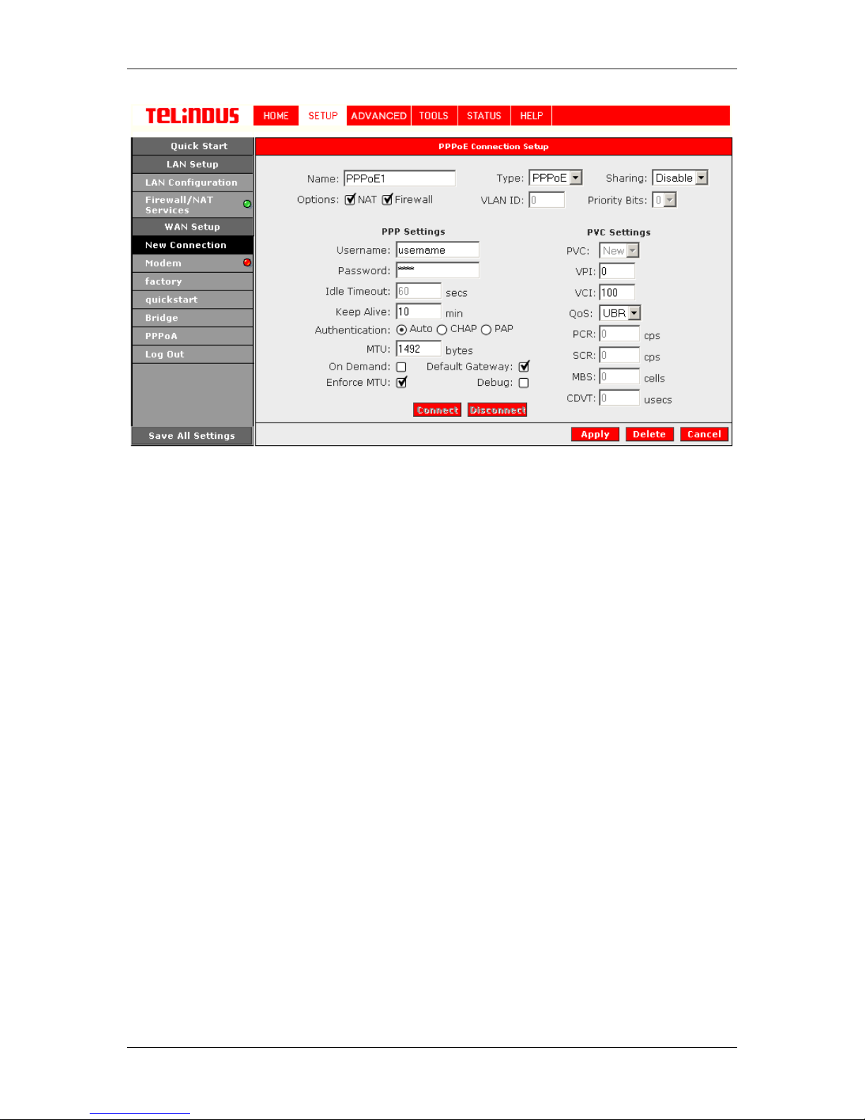
To configure the gateway for PPPoE, click on Setup and then click on New Connection. The
default PPPoE connection setup is displayed. At the Type field select PPPoE and the PPPoE
connection setup page is displayed; Figure 7 illustrates a typical PPPoE configuration. Give your
PPPoE connection a unique name; the name must not have spaces and cannot begin with
numbers. In this case the unique name is called PPPoE1. Select the encapsulation type ( LLC o r
VC); if you are not sure just use the default mode. Select the VPI and VCI settings; your DSL
service provider or your ISP will supply these; in this case the DSL service provider is using
0,100. Also select the ATM Quality of Service (QoS); leave the default value if you ar e unsure or
the ISP did not provide this information.
Following is a description of the dif ferent options:
h. Username: The username for the PPPoE access; this is provided by your DSL
service provider or your ISP.
i. Password: T he pas s wor d f or th e P PP oE acc ess ; this is prov ided by your DS L s erv ic e
provider or your ISP.
j. On-Demand: Enables on-demand mode. The connection will disconnec t if no activity
is detected after the specif ied idle timeout value.
k. Idle Ti meout: Specifies that PPPoE connection should disconnect if the link has no
activity detected for n sec onds. This field is used i n conj unc tion with t he On- Deman d
feature. To ensure that the link is always active, enter a 0 in this field.
l. Keep Alive: When on-demand opt ion is not enable, this value specifies the time to
wait without being con nected to your provider before terminating the connection. To
ensure that the link is always active, enter a 0 in this field.
m. Default Gateway: Specify this connection as the default-route.
n. MTU: Maximum Transmission Unit the DSL c onnect ion c an rec eive. It is a ne goti ated
value that asks the prov ider to sen d packets of no more than n bytes. The maxi mum
specified value is 1500 although some DSL/ISP providers requi re a larger value. The
minimum MTU value is 128.
o. Enforce MTU: Check this box if y ou experi ence pr oblems ac cess ing the Int ernet over
a PPPoE connection. This featur e will force all TCP t raffic to confor m with PPP MRU
by changing TCP Maximum Segment Size to PPP MRU.
Version 2.0 Page 15/52 December 2004
Page 16
TELINDUS TELINDUS 1130/1131 Web Interface User’s Guide
Figure 7 (PPPoE Connection Setup)
To complete the connection you must now click the Apply button. The Apply button will
temporarily save this connection. To make the change permanent, you ne ed to click on
Settings
. At the System Commands page under the TOOLS, c lick on
Save All
.
Save All
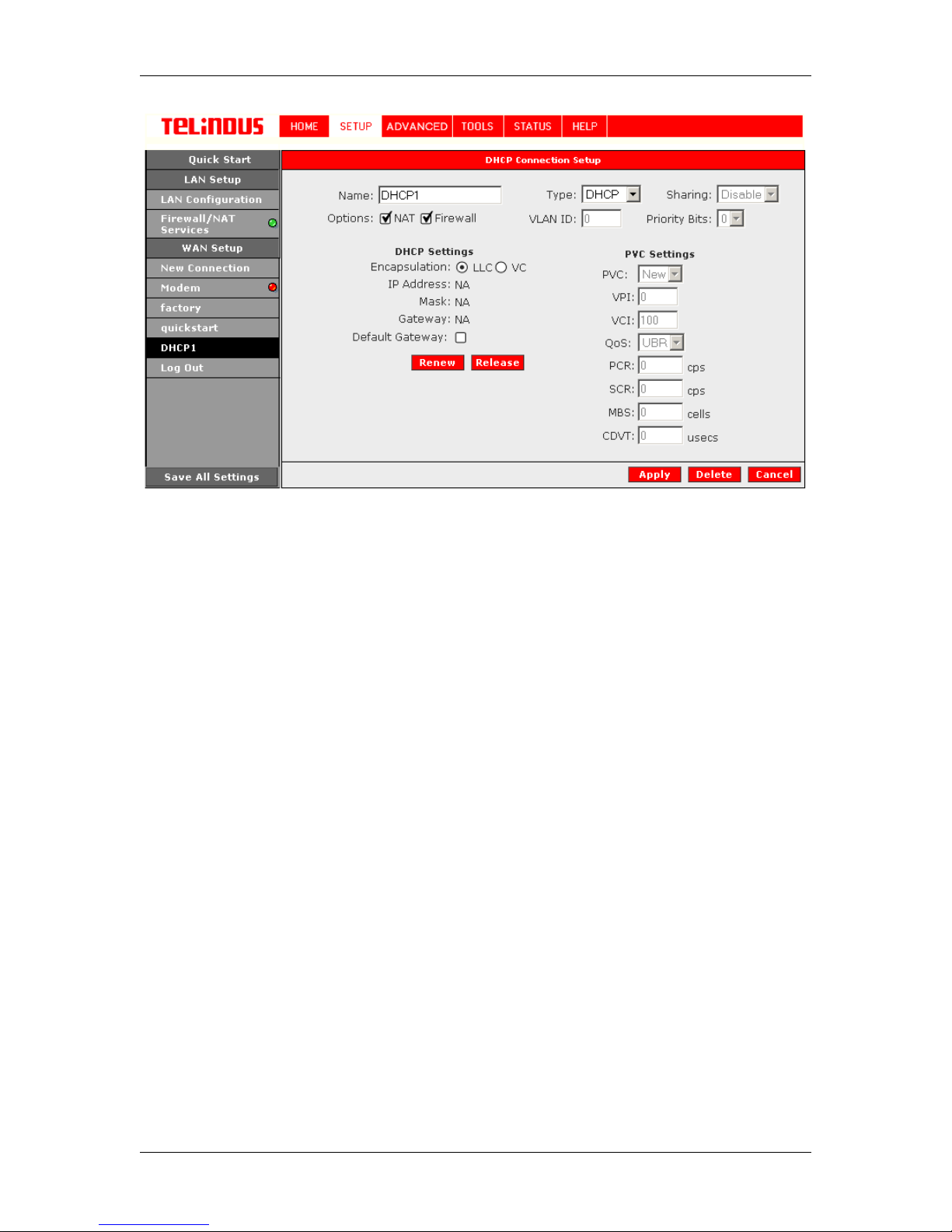
4.4.1.4 DHCP Connection Setup
Dynamic Host Configuration Prot ocol (DHCP ) allows the A DSL Router t o autom atically obt ain t he
IP address from the server. T his option is commonly used in situations wh ere IP is dynamically
assigned and is not known prior to assignment.
To configure the ADSL Router for a DHCP connection, click on Setup and then click on New
Connection. The default DHCP connection setup is displayed. At the Type field select DHCP
and the DHCP connection setup page is displayed; Figure 8 illustrates a typical DHCP
configuration. Give your DHCP connection a unique name; t he name must not have s paces and
cannot begin with numbers. In this case the unique name is called DHCP1. Select the
encapsulation type (LLC or VC); if you are not sure just use the default mode. Select the VPI and
VCI settings; your DSL service provider or your ISP will supply these; in this case the DSL service
provider is using 0,100. Also select the ATM Quality of Serv ice (QoS); leave the def ault value if
you are unsure or the ISP did not provid e this information.
If your DSL line is connected and y our DSL/IPS provider is supporti ng DHCP, you can click the
renew button and the gateway will retrieve an IP address, Subnet mask, and Gateway address.
At anytime, you can renew the DHCP address by clicking on the renew button; in most cases you
will never have to use this button.
Version 2.0 Page 16/52 December 2004
Page 17
TELINDUS TELINDUS 1130/1131 Web Interface User’s Guide
Figure 8 (DHCP Connecti on Setup)
To complete the connection you must now click the Apply button. The Apply button will
temporarily save this connection. To make the change permanent, you ne ed to click on
Settings
. At the System Commands page under the TOOLS, c lick on
Save All
.
Save All
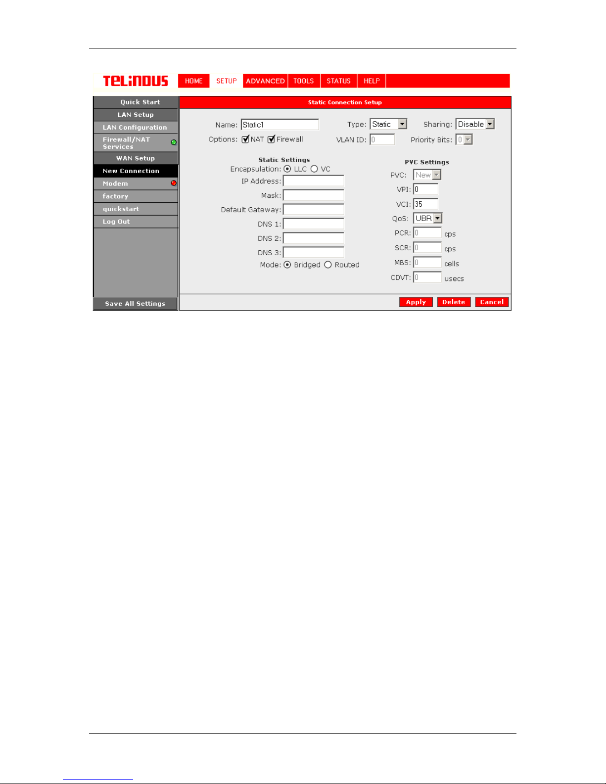
4.4.1.5 Static Connection Setup
Static is used whenever a known static IP is assigned. The accompanying information such as
the Subnet mask and the gate way should also be specified. Up to three Domain N ame Server
(DNS) addresses can also be specified. These servers would enable you to have access to other
web servers. Valid IP addresses range is from 0.0.0.0 to 255.255.255. 2 55.
To configure the ADSL Router for a Static connection, click on Setup and then click on New
Connection. The default Static connect ion setup is displayed. At the Ty pe field selec t Static an d
the Static connection s etup page is displayed; Figure 9 illustrates a typical Static configuration.
Give your Static conn ection a unique name; t he name must not have spaces and cannot begin
with numbers. In this case the unique name is called Static1. Select the encapsulation type (LLC
or VC); if you are not sure jus t use the default mode. Select the VPI and VCI settings; your DSL
service provider or your ISP will supply these; in this case the DSL service provider is using 0,35.
Also select the ATM Qualit y of Se rv ice ( QoS ); leav e t he def ault val ue if y ou are uns ur e or t he I SP
did not provide this inform ation. You can also enable Network Address Translation (NAT) and
the Firewall options. If you are unsure, leave these in the default mode.
Based upon the information your DSL/ISP provided, enter your assigned IP address, Subnet
Mask, Default Gateway (if prov ided), and Dom ain Name S ervices (DNS) v alues (if provide d). For
the static configurat ion, you can also select a bridge connect ion or a routed connection. Sinc e
static IP address is typic ally used to host WEB servers, you may want to use a bridge connection.
Version 2.0 Page 17/52 December 2004
Page 18
TELINDUS TELINDUS 1130/1131 Web Interface User’s Guide
Figure 9 (Static Connec tion Setup)
To complete the connection you must now click the Apply button. The Apply button will
temporarily save this connection. To make the change permanent, you ne ed to click on
Settings
. At the System Commands page under the TOOLS, c lick on
Save All
.
Save All
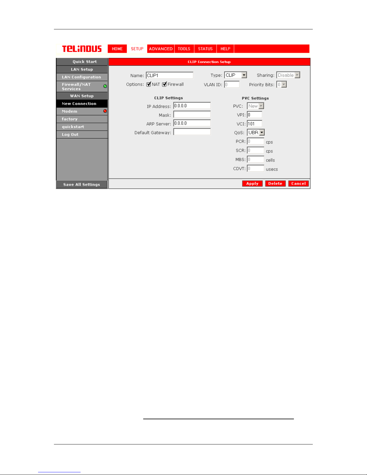
4.4.1.6 Classical IP over ATM (CLIP, defined in RFC1577) Connection Setup
The Classical IP over ATM (CLIP) support provides the ability to transmit IP packets over an ATM
network, CLIP support will encapsulate IP in an AAL5 Packet Data Unit (PDU) frame using
RFC1577and it utilizes an ATM aware version of the ARP protocol (ATMARP only allows for PVC
support; it does not support SVC).
To configure the ADSL Router for a CLIP connection, click on Setup and then click on New
Connection. The defa ult CLIP connection s etup is displayed. At the Type field select CLIP and
the CLIP connection setu p page is displayed; Figure 10 illustrates a typical CLIP configuration.
Give your CLIP connecti on a unique name; the name must not have spaces and c annot begin
with numbers. In this c ase the unique name is called CLIP1. Select the VPI and VCI settings;
your DSL service provider or your ISP will supply these; in this case the DSL service provider is
using 0,101. Also select the ATM Quality of Service (QoS); leave the default value if you are
unsure or the ISP did not provide this information. You can also enable Network Address
Translation (NAT) and the Fi re wall o ptions. If you are unsure, leave these in the def a ult mode.
Based upon the information your DSL/ISP provided, enter your assigned IP address, Subnet
Mask, Default Gateway (if provid ed ), and ARP server IP address.
Version 2.0 Page 18/52 December 2004
Page 19
TELINDUS TELINDUS 1130/1131 Web Interface User’s Guide
Figure 10 (CLIP Connection Setup)
To complete the connection you must now click the Apply button. The Apply button will
temporarily save this connection. To make the change permanent, you ne ed to click on
Settings
. At the System Commands page under the TOOLS, c lick on
Save All
.
Save All
4.4.2 Modify an Existing Connection
To modify an existing connec tion, click setup and then clic k the connection you want to m odify.
The connections are list ed as Connection 0 through Connection 7
If you delete the connection, to make the change permanent, you need to click on
Settings
. At the System Commands page under the TOOLS, c lick on
Save All
.
Save All
4.4.3 Modem setup
To configure the DSL modulation type, Click on SETUP. Under WAN Setup, select Modem. This
will bring up the modem setup screen. Leave the default value if you are unsure or the DSL/ISP
did not provide this information. For most all cases , this screen should not be modified.
The Apply button will temporarily save this connecti on. To make the change permanent, you need
to click on
All
.
Save All Settings
. At the System Commands page under the TOO LS, click on
Save
4.5 Configuring the LAN
By default, your ADSL Rout er has DHCP s erver (LA N si de) ena bled. If you alread y have a D HCP
server running on your network,
Version 2.0 Page 19/52 December 2004
you must disable one of the two DHCP servers (!!!)
; if you
Page 20
TELINDUS TELINDUS 1130/1131 Web Interface User’s Guide
plug a second DHCP server int o the net work, you will expe rience net work err ors and t he networ k
will not function normally.
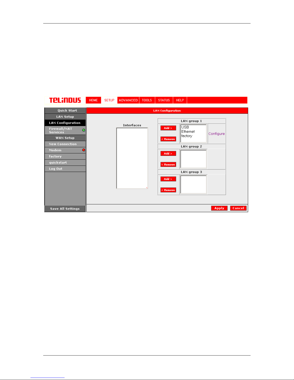
You can define different LAN groups in the ADSL Router. This allows to make a distinction
between different connection types on one and the same modem. Three LAN Groups can be
defined and different virt ual interfaces (real interf ace or virtual connect ion) can be assigned to a
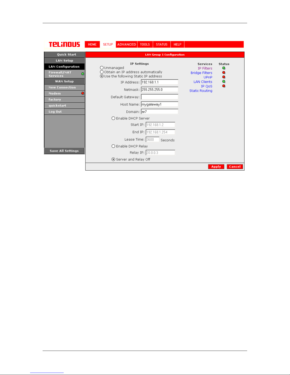
specific LAN group. Under SETUP select LAN Configuration (Figure 11) and configure the
different LAN groups with t he physical and virtual interfaces (def ined under WAN Setup). In the
example a LAN group is defined with the USB interface, the Ethernet interface and the predefined connection
factory
. See Figure 11.
Figure 11 (LAN Configuration)
4.5.1 Configure a LAN group
A LAN group can be configured by clicking on
Figure 11). This opens a windo w into the LAN group X Configuration (with X=1, 2 or 3). See
Figure 12 (LAN Group 1 Configu ration).
In this window it is possible to configure:
- IP address
- DHCP server
- Additional parameters associated with the LAN group
IP Filters
Bridge Filters
UpnP
LAN Clients
IP QoS
Routing
These additional parameters are discussed in the ADVANCED section.
Configure
in the LAN configuration screen (see
Version 2.0 Page 20/52 December 2004
Page 21
TELINDUS TELINDUS 1130/1131 Web Interface User’s Guide
Figure 12 (LAN Group 1 Configu ration)
4.5.1.1 Static IP address assignment
Your ADSL Router’s default IP address and subnet mask are 192.168.1.1/255.255.255.0; this
subnet mask will allow the ADSL Router to support 254 users. If you want to support a larger
number of users you can change th e subnet mas k. But remember, the DHCP server is def aulted
to only give out 255 IP addresses. Further remember that if you change your gateways’ IP
address and you have DHCP enabled, the DHCP configuration must reside within the same
subnet.
The default gateway is the routing device used to forward all traffic that is not addressed to a
station within the local subnet. Your ISP will provide you with the default gateway Address.
The hostname can be any alphanumeric word that does not contain spaces. The domain name is
used to in conjunction wit h the host name t o uniquely ident ify the gate way. To access the ADSL
Router’s web pages the user can type 192.168.1.1 (the default IP address) or type
mygateway.ar7.
4.5.1.2
You can obtain the IP address automatically from your provider by selecting: Obtain an IP
Address Automatically
4.5.1.3
Automatic IP address assignment
LAN IP address assignment with DHCP
Version 2.0 Page 21/52 December 2004
Page 22
TELINDUS TELINDUS 1130/1131 Web Interface User’s Guide
The DHCP server can be enabled or disabled. Start IP is the number from which the DHCP
server starts issuing I P addresses. This value must be gre ater than the AD SL Router IP addr ess
value. For example if the ADSL Rout er IP address is 192.168.1.1 (default ) than the starting IP
address must be 192.168.1. 2 (or higher).
End IP is the number from which the DHCP server stops issuing IP addresses. The ending
address cannot exceed a subnet limit of 254. Hence the max v alue for our default gateway is
192.168.1.254. If the DHCP server runs out of DHCP addresses, users will not get access to
network resources. If this happens you can increase the Ending IP address (to the limit of 255) or
reduce the lease time.
The Lease Time is the amount of time a network user will be allowed connection to the ADSL
Router with their current dynamic IP address. The amount of time is in units of minutes; the
default value is 3600 minutes (60 hours).
Note: If you change the start or end values, make sure the values are still within the same subnet
as the router IP addres s. In ot her wor ds, if t he rout er IP ad dres s is 19 2.1 68.1. 1 (def ault ) a nd y ou
change the DHCP start/end IP addresses to be 192.128.1.2/192.128.1.100, you will not be able
to communicate to the ADSL Router if you r PC has DHCP enabled.
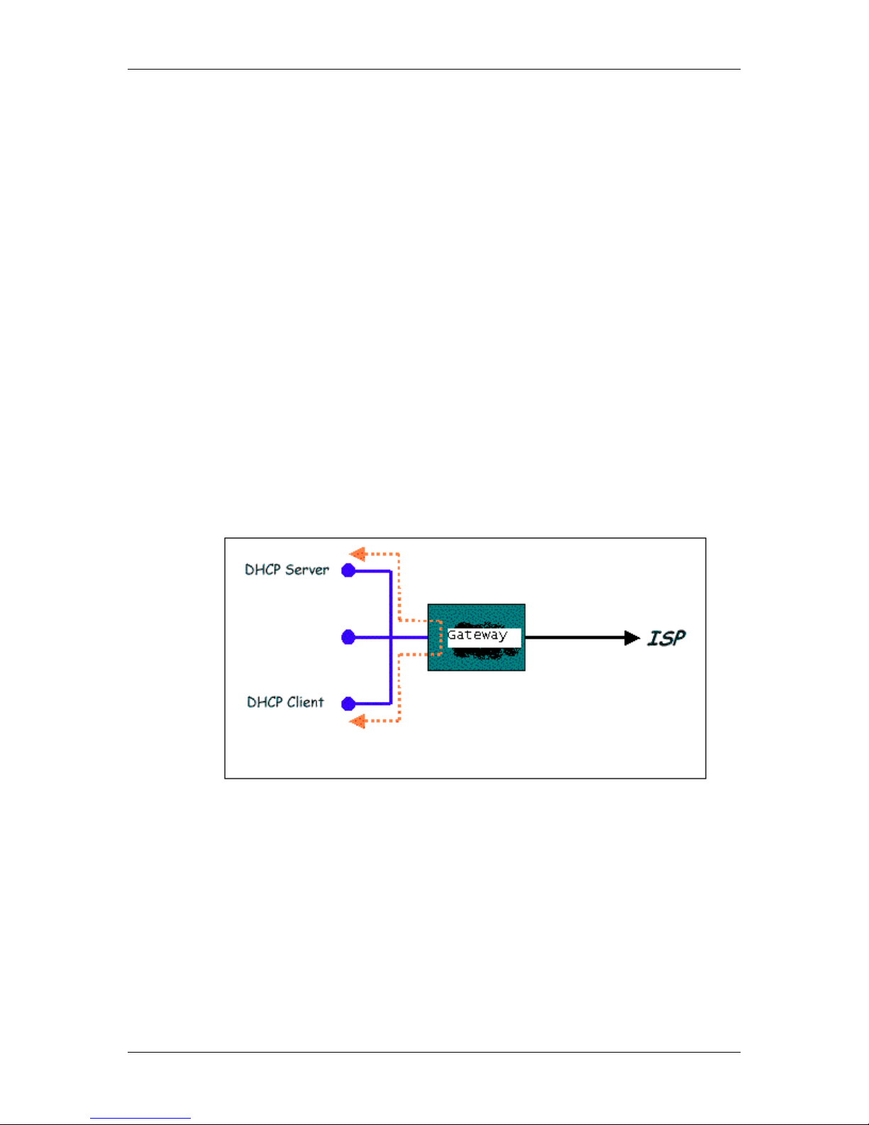
In addition to the DHCP server feature, the ADSL Router supports the DHCP relay function.
When the ADSL Router is configur ed as DHCP server, it assigns the IP addres ses to the LAN
clients. When the ADSL Router is configured as DHCP relay, it is responsible for forwarding the
requests and responses ne gotiating between the DHCP clients and the server. See figure 13.
Figure 13 (Example of a DHCP Relay configuration)
By turning off the DHCP server a nd relay the network administ rator must carefully configure t he
IP address, Subnet Mas k and DNS settings of every comput er on your network. Do not ass ign
the same IP address to mor e than one computer and your ADSL Rout er must be on the same
subnet as all the other computers.
Version 2.0 Page 22/52 December 2004
Page 23
TELINDUS TELINDUS 1130/1131 Web Interface User’s Guide
The Apply button will temporarily save these settings. To make the change permanent, you need
to click on
All
.
Save All Settings
. At the System Commands page under the TOO LS, click on
Save
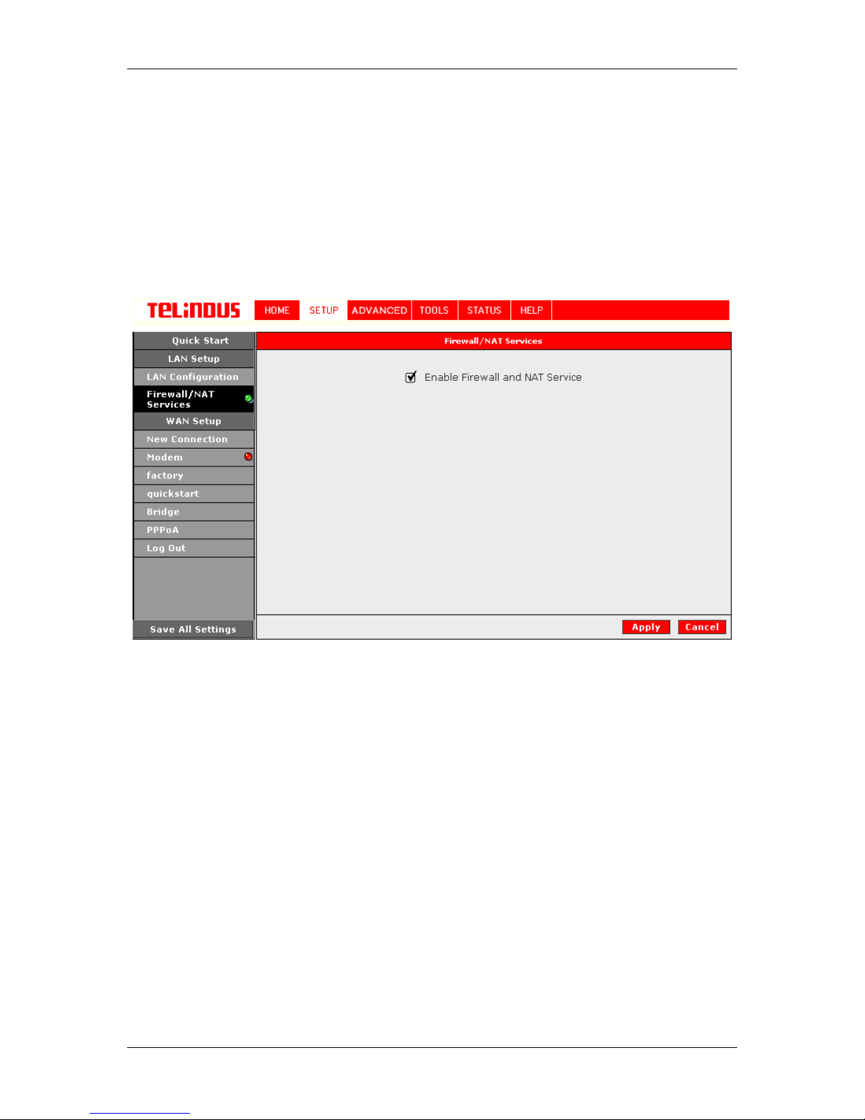
4.5.2 Firewall/NAT Services
You can enable or disable Firewall and NA T by clicking on SE TUP and under LAN S etup, select
Firewall/NAT Services. By uns el ec t ing t he “E na bl e Fi rewall and NAT Services” button the f ire wall
and NAT services is disabled for all WA N connections (Figure 14)
Figure 14 (Firewall/NAT Services)
The Apply button will temporarily save these settings. To make the change permanent, you need
to click on
All
.
Save All Settings
. At the System Commands page under the TOO LS, click on
Save
Version 2.0 Page 23/52 December 2004
Page 24
TELINDUS TELINDUS 1130/1131 Web Interface User’s Guide
4.6 ADVANCED (for advanced users only)
The ADSL Router supports a host of advanced features. For basic ADSL Rout er functionality,
the user does not need to utilize these advanced features. The features help with routing,
security, port configuration, management and Plug and Play capability.
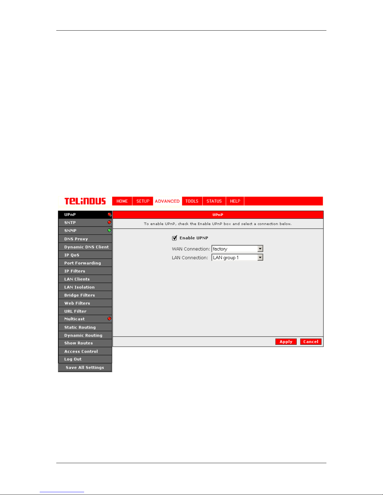
4.6.1 UPnP
UPnP NAT and Firewall T raversal allow traffi c to pass-through the ADSL Router for appli cations
using the UPnP protocol. This feature requires one active DSL connection. In presence of
multiple DSL connections, select the one over which the incoming traffic will be present, for
example the default Intern et connection.
To enable UPnP, you must fi rst have a WAN conn ection conf igured. Once a WAN connecti on is
configured, click ADVANCED and select UPnP. This will bring up the s creen shown in Figure 15.
You must enable UPnP and then select which c onnec tion will utilize UPnP.
The Apply button will temporarily save these settings. To make the change permanent, you need
to click on
All
.
Save All Settings
Version 2.0 Page 24/52 December 2004
Figure 15 (UPnP)
. At the System Commands page under the TOO LS, click on
Save
Page 25

TELINDUS TELINDUS 1130/1131 Web Interface User’s Guide
4.6.2 SNTP
It is possible to synchronize the ADSL Router with an external S NTP server. The SNTP screen
allows you to enable this option and to provide the required parameters to synchronize on this
external clock. See Figure 16 (S NT P). Allow about 15 minutes for the Router to contact the Time
Server to get a response. The “system log” will be able to reflect the updated time upon
successfully connected the t i me server.
Figure 16 (SNTP)
The Apply button will temporarily save these settings. To make the change permanent, you need
to click on
All
.
Save All Settings
. At the System Commands page under the TOO LS, click on
Save
Version 2.0 Page 25/52 December 2004
Page 26
TELINDUS TELINDUS 1130/1131 Web Interface User’s Guide
4.6.3 SNMP
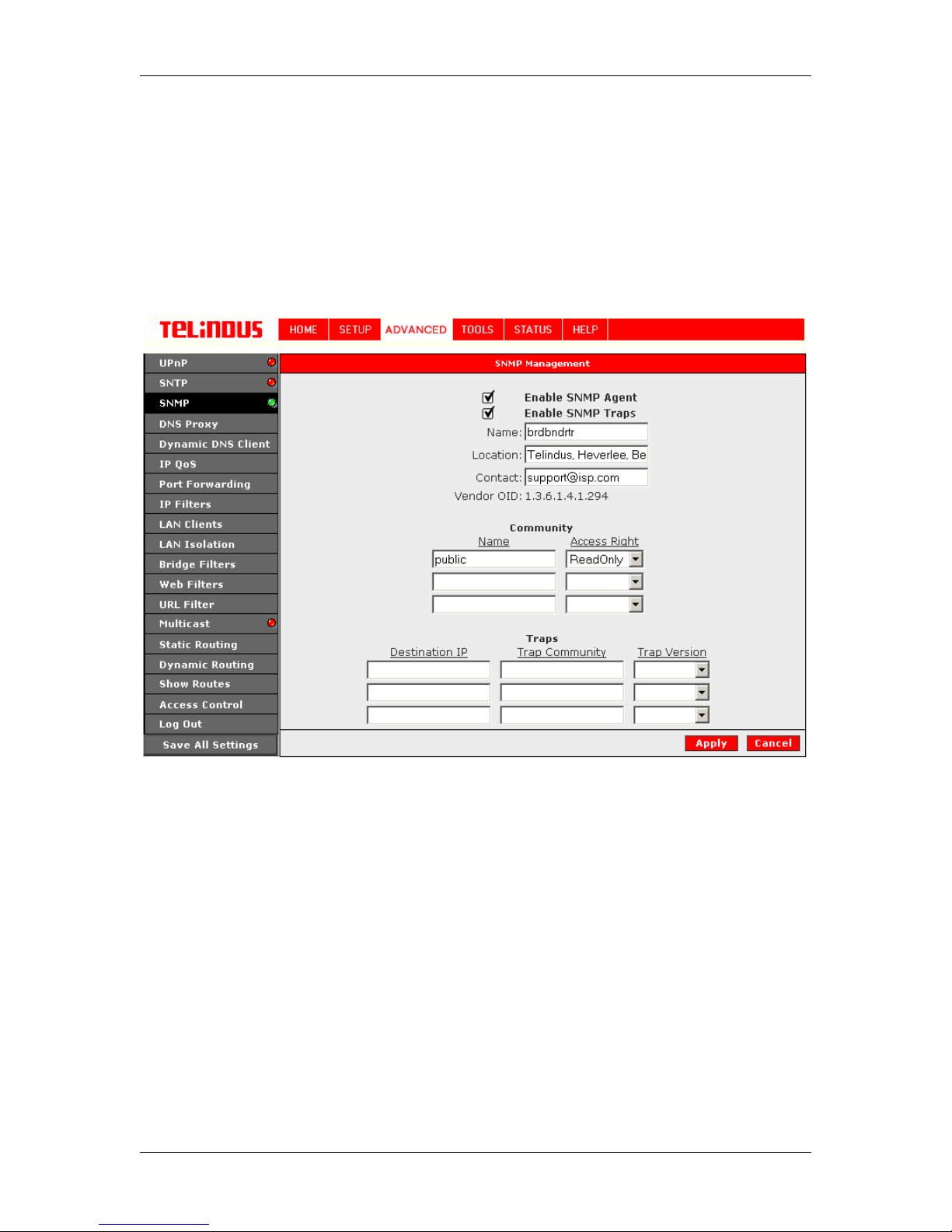
The 1130/1131 ADSL Router s upports SNMP. It has a local SNMP agent and can send SNMP
traps to any other host on the Int er n et. Configuration of the SNMP functionality is s ho wn in Figure
17 (SNMP Management).
Both the SNMP agent and the traps can be enabled or disabled. Basic Inf ormation can be
entered in the Name, Location and Co ntact fields. In addition Community names can be defined
with different Access Rights and the Trap Destination addresses can be entere d.
Figure 17 (SNMP Management)
The Apply button will temporarily save these settings. To make the change permanent, you need
to click on
All
.
Save All Settings
. At the System Commands page under the TOO LS, click on
Save
Version 2.0 Page 26/52 December 2004
Page 27
TELINDUS TELINDUS 1130/1131 Web Interface User’s Guide
4.6.4 DNS Proxy
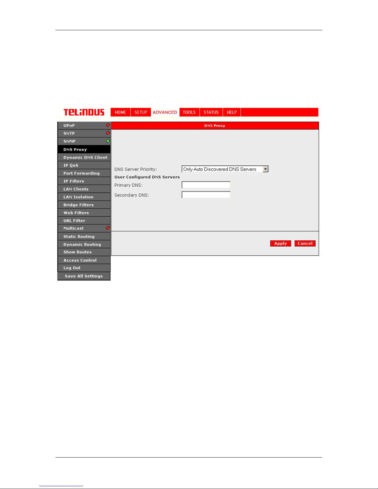
This feature allows the user to select the (Domain Name Server) DNS Server Priority as well as
enter IP addresses for Primary DNS and secondary DNS.
Figure 18 (DNS Proxy)
The Apply button will temporarily save these settings. To make the change permanent, you need
to click on
All
.
Save All Settings
. At the System Commands page under the TOO LS, click on
Save
Version 2.0 Page 27/52 December 2004
Page 28
TELINDUS TELINDUS 1130/1131 Web Interface User’s Guide
4.6.5 Dynamic DNS Client
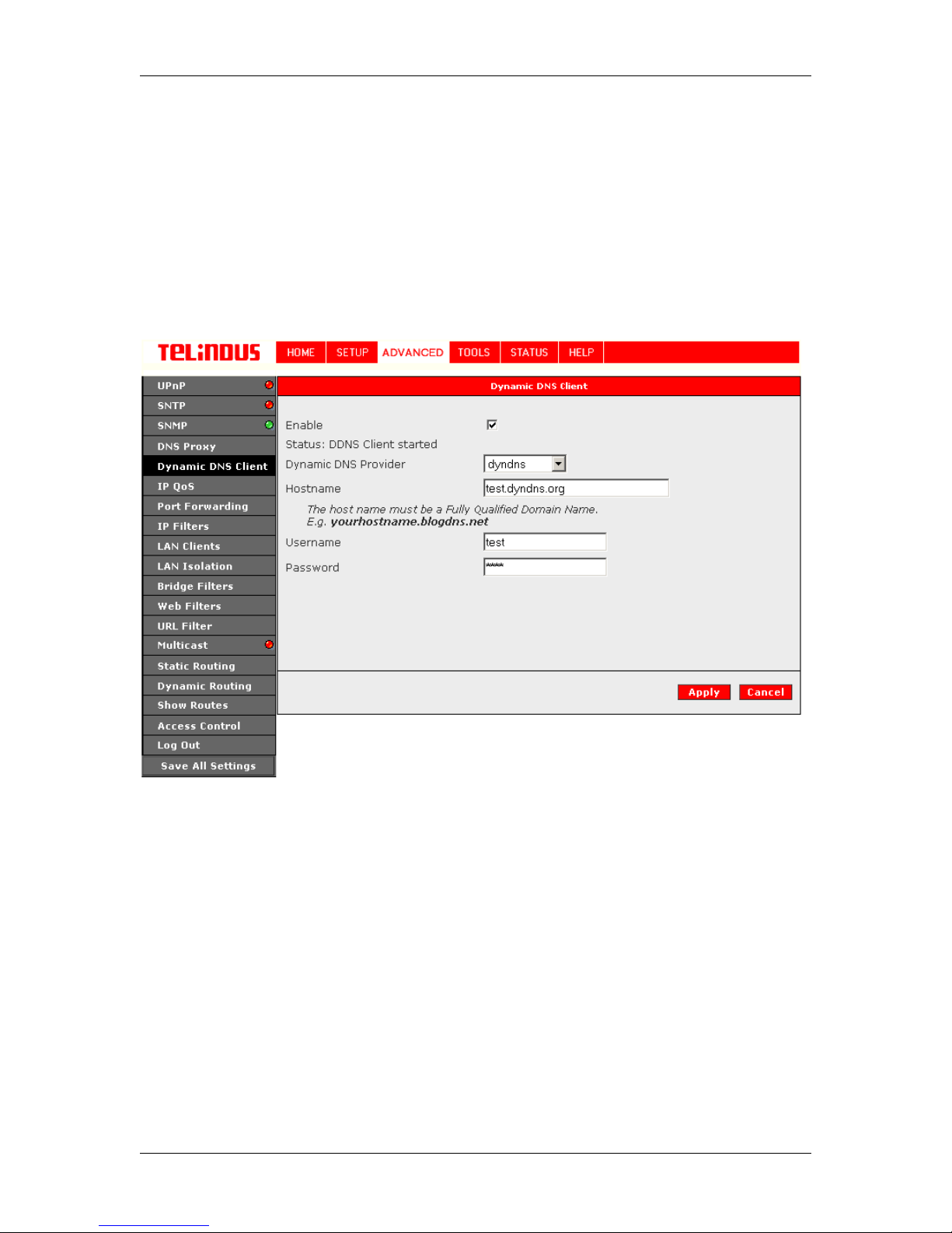
Dynamic DNS allows the user to register wit h a Dynamic DNS Provider as listed. The dynamic
DNS will be linked with the WAN IP of the router even after the ISP update t he WAN IP to another
IP address. It can be useful in web hos ting and FTP services.
Note: The Username/Passwo rd entered should be similar to the Username/P assword you have
specified during the registration of the DNS hostname.
The Apply button will temporarily save these settings. To make the change permanent, you need
to click on
All
.
Save All Settings
Version 2.0 Page 28/52 December 2004
Figure 19 (Dynamic DNS Client)
. At the System Commands page under the TOO LS, click on
Save
Page 29

TELINDUS TELINDUS 1130/1131 Web Interface User’s Guide
4.6.6 IP QoS
IP QoS services from the Network Service P rovider (NSP) is applicable to the output device
(Egress side). Meaning the IP QoS traffic shaping is associated with any transmitted traffic from
the perspective of the NSP. E ach output device has 3 priority queues associ ated with transmit
data. The High priority queue has strict priority over medium and low priority queues. The Medium
and Low priority queues are s erviced on a Round Robin priority basis according to the configured
weights (WRR), after t he High priority queue has been completely servic ed.
The "IP QoS" section under "Advanced section" allows you to setup IP QoS for a connect i on.
The "IP QoS" section has two sub-sec tions - QoS Setup Page
and Rule Setup Page.
4.6.6.1
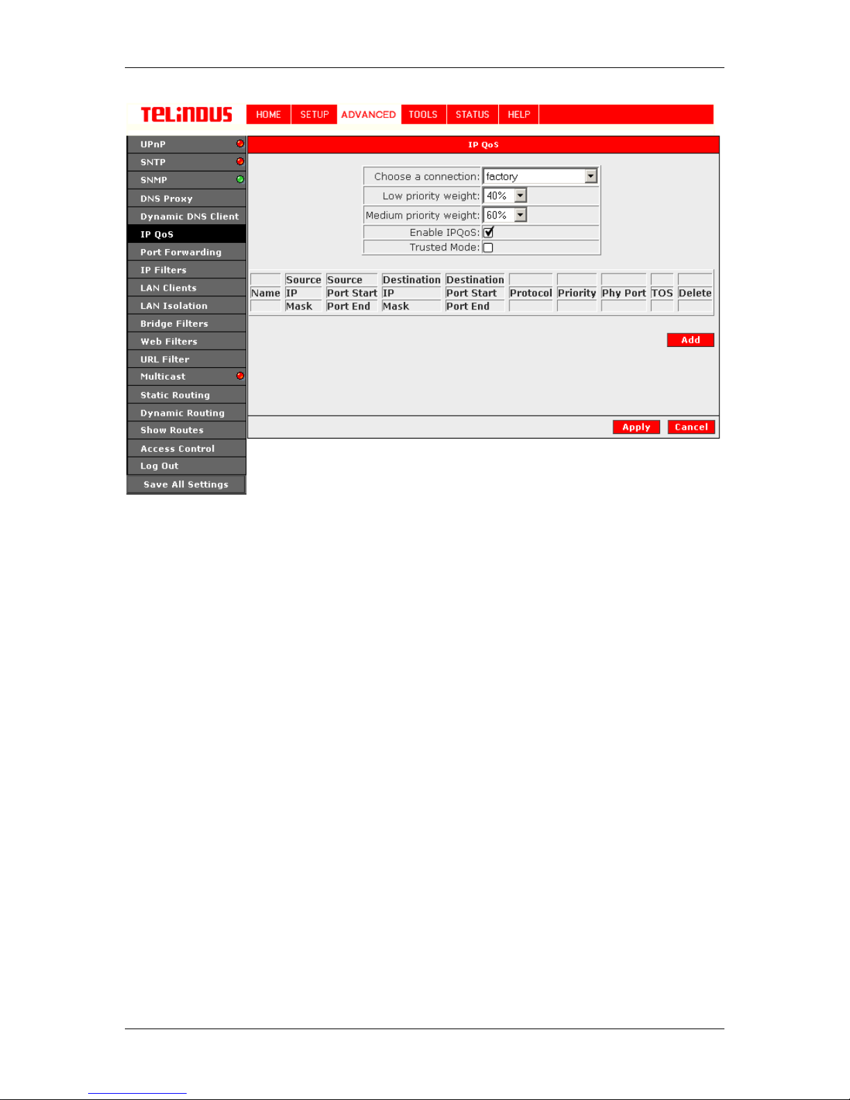
The QoS setup page allows yo u to configure IP QoS for a connection, to v iew the configured QoS
rules and to add/delete a Q oS rule. See Figure 20 (QoS Setup Page).
Choose a connection:
connections. For e.g. Choose a WAN connection to enable IP QoS f or the Upstream traffic of the
Modem. On the other hand choose the LAN connection (Ethernet and USB Bridged ) for the
downstream traffic.
Low/Medium priority weig h ts:
and Low priority queues in increments of 10 percent, so that that the sum of the weights of these
2 queues is equal to 100 percent.
Enable IP QoS:
Trusted Mode:
prioritization - Trusted and Un-trusted. This field allows you to choose the mode - Trusted
(checked) and Un-trusted (Unchecked).
In "Trusted mode" all the rules will be applied first, regardless of the setting of the TOS bits. After
the rules have been exhausted the existing TOS bit settings will be honored. The "Un-trusted"
mode will match first against all rules as in "Trusted" mode. The difference is that if there is no
match then a default rule will be used. The default rule will have an associated queuing priority Low.
Rules section:
allows you to delete an existi ng rule.
Each rule is a Matching criteria that ident i fies an Application traffic to be transmitted by t he NSP
using one of the 3 Priority Queues - Hig h, Medium a nd Low.
Note:
Default Rule puts all the Traffic to be transmitted in the Low Priority Queue
QoS Setup Page
This field allows you choose a connection from the list of available
These 2 fields will allow you to select the weights of the Medium
This field allows you to enable/disable IP QoS for the c hos en connection.
The NSP has two primary modes of operation with regard to queue traffic
This section displays a list of configured rules, allows you to add a new rule and
If IP QoS is enabled and no rules are def i ned, a Default Rule is added which is hidden. The
.
Version 2.0 Page 29/52 December 2004
Page 30
TELINDUS TELINDUS 1130/1131 Web Interface User’s Guide
Figure 20 (QoS Setup Screen)
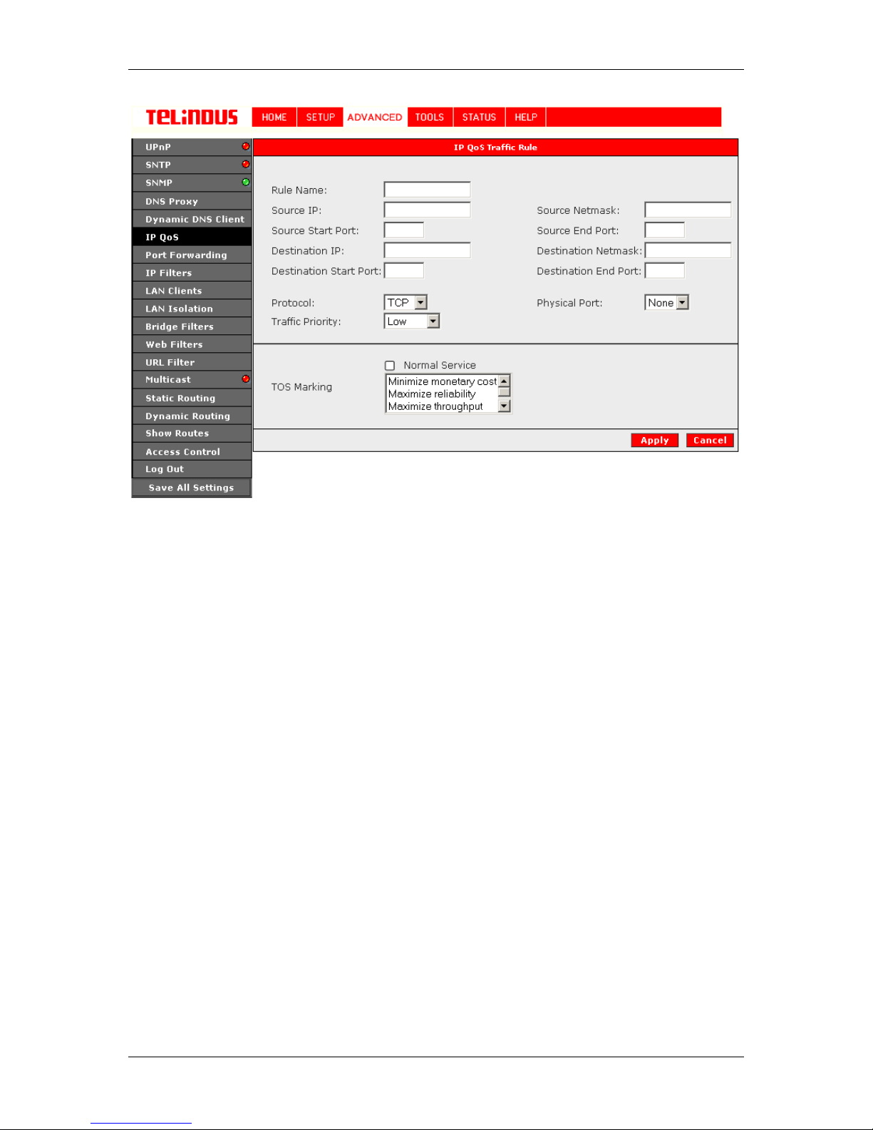
4.6.6.2
This page is invoked when you click on the "Add" button of "QoS Setup Page". See Figure 21
(Rules Setup Page). This page all o ws y ou add a Rule or Matching criteria that identifies an
Application traffic. The Applic ation traffic can be identified by Rule Name, S ource/Destination IP
Address and Netmask, Sourc e/Destination Port range, Protoc ol an d Traffic Priority.
The Traffic Priority field corresponds to the Priority Queue (High/Medium/Low) for for this traffic.
The possible options for Protoc ol ar e - ANY, ICMP, TCP and UDP. Wildcard(*) entries are
allowed for IP Address/Netmask and Port range fields.
The additional TOS marking field allows you to as sign a TOS value to this traffic. The values for
the TOS marking can be - No Change, Normal S e rvice, Minimize monet ary cost, Maximize
reliability, Maximize throughput and Minimize delay.
Rule Setup Page
Version 2.0 Page 30/52 December 2004
Page 31
TELINDUS TELINDUS 1130/1131 Web Interface User’s Guide
Figure 21 (IP QoS Traffic Rule)
The Apply button will temporarily save these settings. To make the change permanent, you need
to click on
All
.
Save All Settings
. At the System Commands page under the TOO LS, click on
Save
Version 2.0 Page 31/52 December 2004
Page 32
TELINDUS TELINDUS 1130/1131 Web Interface User’s Guide
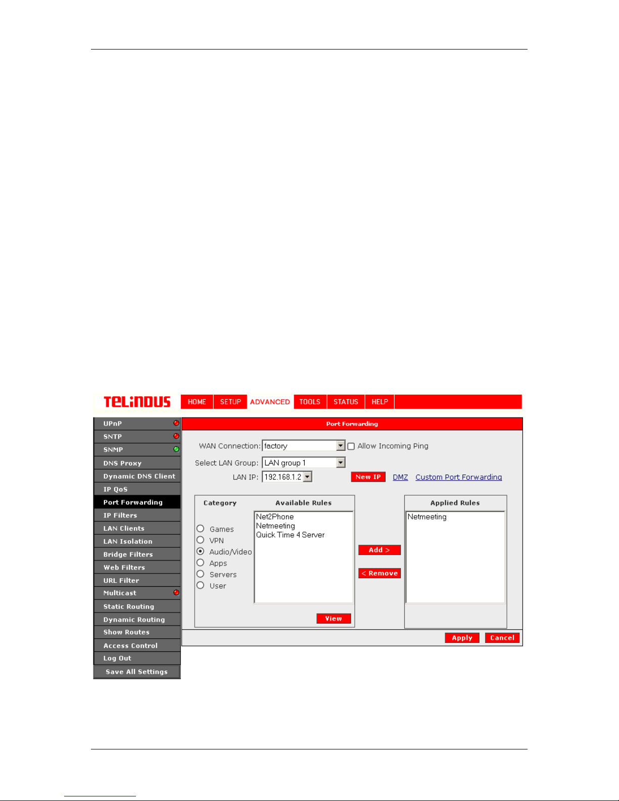
4.6.7 Port Forwarding
Using the Port Forwarding page, you can provide local services (for example web hosting) for
people on the Internet or play Internet games. When users send this type of request to your
network via the Internet, the ADSL Router will forward those requests to the appropriate PC. Port
forwarding can be used with DHCP assigned addresses but remember that a DHCP address is
dynamic (not static). For example, if you were c onfiguring a Netmeetin g server, you woul d want
to assign this server a stat ic IP address so that the IP address is not reassigned. Als o remember
that if an Internet user is trying to access an Internet application, they must use the WAN IP
address. The port forwarding will translate the WAN IP address into a LAN IP address.
To configure a service, game, or other application select the external connection (for example the
Internet connection), from the HOME screen, click ADVANCED and s elect P ort Forwarding. Next
select the computer host ing the service and add the corresponding fir ewall rule. If you want to
add a custom application, select the User category, click New and fill in the port, protocols and
description for your application.
For example, if you want to host a Netmeeting session, from the HOME screen, click ADVANCED
and select Port Forwarding. First select the IP address for your Netmeeting server. Next select
the Audio/Video cate gory and add Netmeeting to the ap plied rules box. To view the management
rules, highlight Netmeeting and select view; this will display the pre configured protocols and
ports that Netmeeting will use. Now assuming that your WAN connection is correct, you can run
Netmeeting from your server and call users that are on the Internet. If you know your WAN IP
address, users can call you.
Version 2.0 Page 32/52 December 2004
Figure 22 (Port Forwarding: Netmeeting)
Page 33
TELINDUS TELINDUS 1130/1131 Web Interface User’s Guide
4.6.7.1 DMZ configuration
Setting a computer (on your local network) as a DMZ forwards any network traffic that is not
redirected to another com puter via t he port-forwa rding featur e to the compute r's IP address . This
opens the access to the DMZ computer from the Internet.
The Apply button will temporarily save these settings. To make the change permanent, you need
to click on
All
.
Save All Settings
. At the System Commands page under the TOO LS, click on
Save
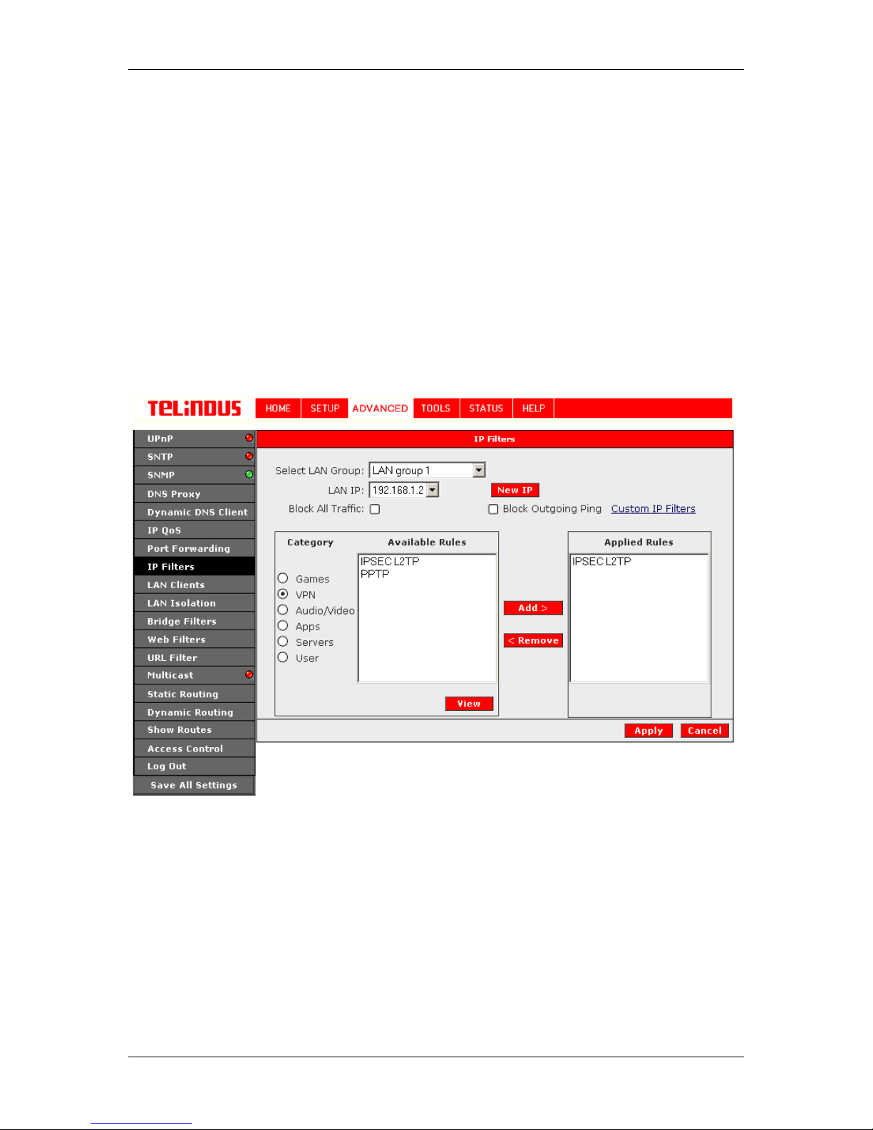
4.6.8 IP Filters
IP filters allow to configure the Firewall to block all or specific types of IP traffic. See Figure 23 (IP
Filters). It is also possible to build Custom IP Filters.
The Apply button will temporarily save these settings. To make the change permanent, you need
to click on
All
.
Save All Settings
Version 2.0 Page 33/52 December 2004
Figure 23 (IP Filters)
. At the System Commands page under the TOO LS, click on
Save
Page 34
TELINDUS TELINDUS 1130/1131 Web Interface User’s Guide
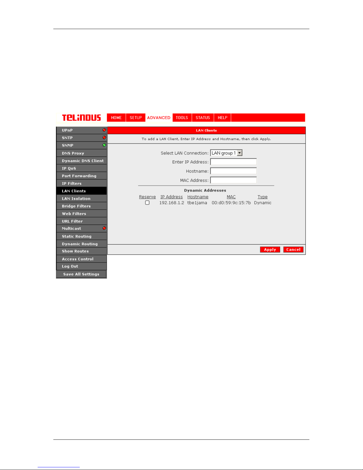
4.6.9 LAN Clients
To add a LAN client, click ADVANCED and select LAN Clients. If DHCP is used, all DHCP
clients are automatically as signed. If a fixed I P address server is on t he LAN and you want t his
server to be visible vi a the WAN, you must add its IP address . Once the IP address has been
added to you can apply Port Forwarding an d Access Control rul es to this IP addres s. See Figur e
24 (LAN Clients).
Figure 24 (LAN Clients)
The Apply button will temporarily save these settings. To make the change permanent, you need
to click on
All
.
Save All Settings
. At the System Commands page under the TOO LS, click on
Save
Version 2.0 Page 34/52 December 2004
Page 35
TELINDUS TELINDUS 1130/1131 Web Interface User’s Guide
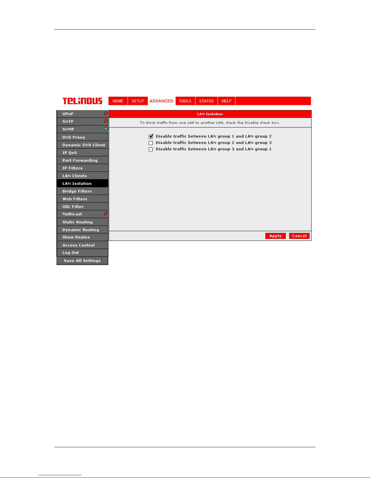
4.6.10 LAN Isolation
Enables or disables Traffic between the different defined LA N groups. This feature can be used to
connect two completely indepe nd ent broadband users over the same ADSL connection.
Figure 25 (LAN Isolation)
The Apply button will temporarily save these settings. To make the change permanent, you need
to click on
All
.
Save All Settings
. At the System Commands page under the TOO LS, click on
Save
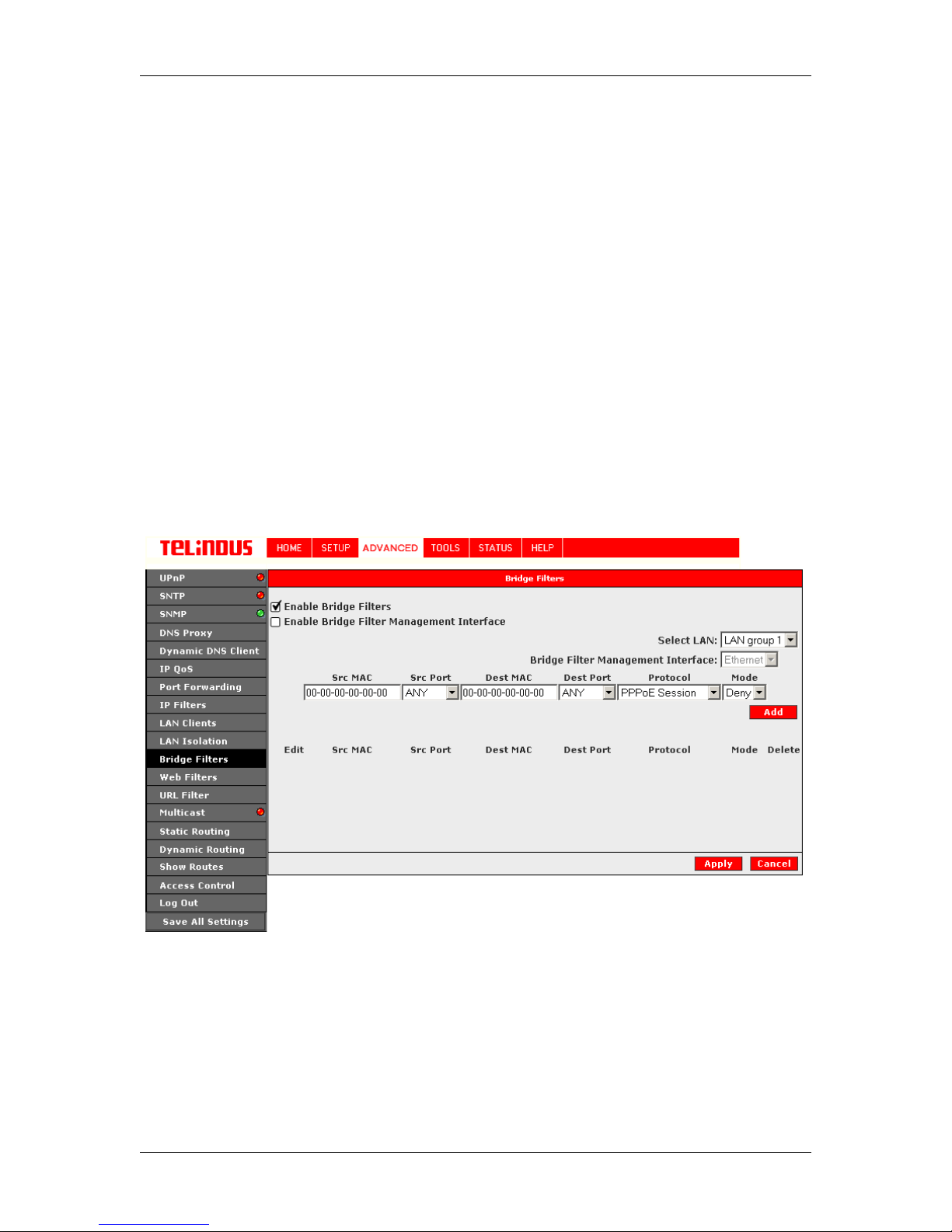
4.6.11 Bridge Filters
The bridge filtering mechanis m prov id es a way for the users to define rules to allow/deny frames
through the bridge based on source MAC address, destination MAC addres s and/or frame type.
When bridge filtering is enabled, each frame is examined against the each defined filt er rules
sequentially, and when a matched is determined, the appropriate fi ltering action (determined by
the access type selected ... i.e allow or deny) is performed. The user shoul d note that the bridge
filter will only examined frames from interfaces which is part of the bridge itself. Twenty filter rules
are supported with bridge filt ering. See Figure 26 (Bridge Filters).
The User Interface for Bridge Filter allows the user to add/edit/delete, as well as, enable the filter
rules. To add a rules, simply define the source MAC address, destination MAC address and
frame type with desired filtering type (i.e. allow/deny), and press the "Add" button. The MAC
address must be in a xx-xx-xx-xx-xx-x x format, with 00-00-00-00-00-00 as "don't care". Blanks
can be used in the MAC address space, and would be considered also as " don' t care".
Version 2.0 Page 35/52 December 2004
Page 36
TELINDUS TELINDUS 1130/1131 Web Interface User’s Guide
To edit/modify an exist filter rule, select the desired rule created previously from "Add" in the
"Edit" select box. The selected filter rule will appear on top section, as with the "Add" filter rule.
Make the desired change to the MAC address, frame type and/or access type, an d press "Apply".
To delete filter rule(s), select the filter rule entry to delete in the "Delete" selection box. Note that
multiple deletion is possible. Once all t he des ire d filter rule(s) is/are selected for deletion, press
the "Apply" button. The "Select All" select box can also be used to delete all the filter rule. It
provides a quick method of select ing all filter rules for deletion.
The "Enable Bridge Filters" button allow the user to enable or disable bridge filtering. It can be
set/unset during any add/edit/delete operation. It can also be set/unset independently by just
pressing the "Apply" button.
Note: On a windows based machine, to find a MAC address, at a dos prompt type
Note: There are three hidd en filter rules within the bridge filter table. These rules are entered
automatically by the system to ensure the user does not "lock" themselv es out of the system. The
first rule allows any and all ARP frames thro ug h the system. The second rule allows all IPv4
frames with the destination MAC addr ess of the bridge to go through. The third rule allows all
IPv4 frames with the source MA C add ress of the bridge to go through.
ipconfig /all
.
The Apply button will temporarily save these settings. To make the change permanent, you need
to click on
All
.
Save All Settings
Version 2.0 Page 36/52 December 2004
Figure 26 (Bridge Filters)
. At the System Commands page under the TOO LS, click on
Save
Page 37
TELINDUS TELINDUS 1130/1131 Web Interface User’s Guide
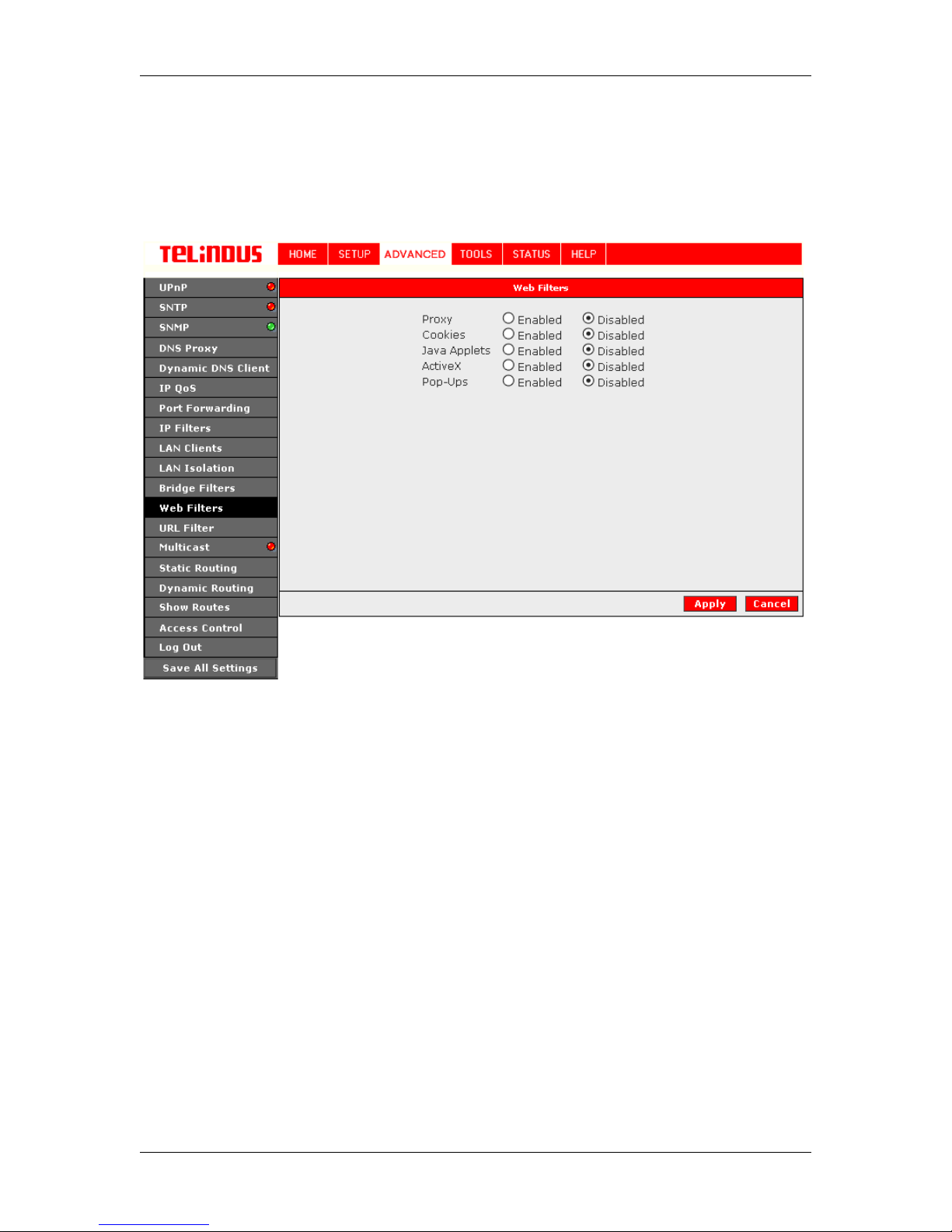
4.6.12 Web Filters
The Web Filter allows to filter certain types of Web Applications like Cookies, JAVA, AciveX or
Pop-Ups. See Figure 27 (Web Filters ).
Figure 27 (Web Filters)
The Apply button will temporarily save these settings. To make the change permanent, you need
to click on
All
.
Save All Settings
. At the System Commands page under the TOO LS, click on
Save
Version 2.0 Page 37/52 December 2004
Page 38
TELINDUS TELINDUS 1130/1131 Web Interface User’s Guide
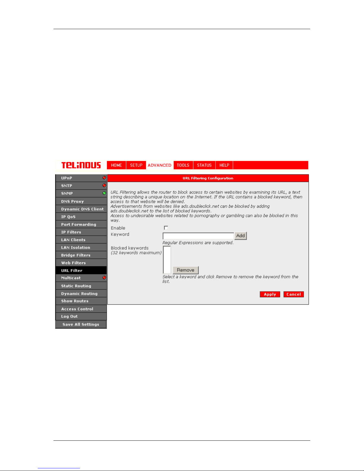
4.6.13 URL Filter
URL Filtering allows the router to block access to certain websites by examining its URL, a text
string describing a unique locati on on the Internet. If the URL contains a blocked keyword, then
access to that website will be denied. See Figure 28 (URL Filtering Configuration)
Advertisements from websites like
ads.doubleclick.net
Access to undesirable websites related to pornography or gambling can also be blocked in this
way.
to the list of blocked keywords.
ads.doubleclick.net
can be blocked by adding
The Apply button will temporarily save these settings. To make the change permanent, you need
to click on
All
.
Save All Settings
Version 2.0 Page 38/52 December 2004
Figure 28 (URL Filtering Configuration)
. At the System Commands page under the TOO LS, click on
Save
Page 39
TELINDUS TELINDUS 1130/1131 Web Interface User’s Guide
4.6.14 Multicast
Multicasting is a form of limited broadcast. UDP is used to send datagrams to all hosts that
belong to what is called a " host group." A host group is a set of zero or more hosts identif ied by
the same destination IP address. The following statements apply to host groups.
a. Anyone can join or leave a host group at will.
b. There are no restrictions on a host's location.
c. The r e a re no restrictions on the number of members that may belong to a host group.
d. A host may belong to multiple host groups.
e. Non-group members may send UDP datagrams to the host group.
Multicasting is useful wh en data nee ds to be sent to more than one other d evice. For ins tance, if
one device is responsible f or acquiring data t hat many other dev ices need, then mult icasting is a
natural fit. Note that using multicasting as opposed to sending the same data to individual devices
uses less network band width.
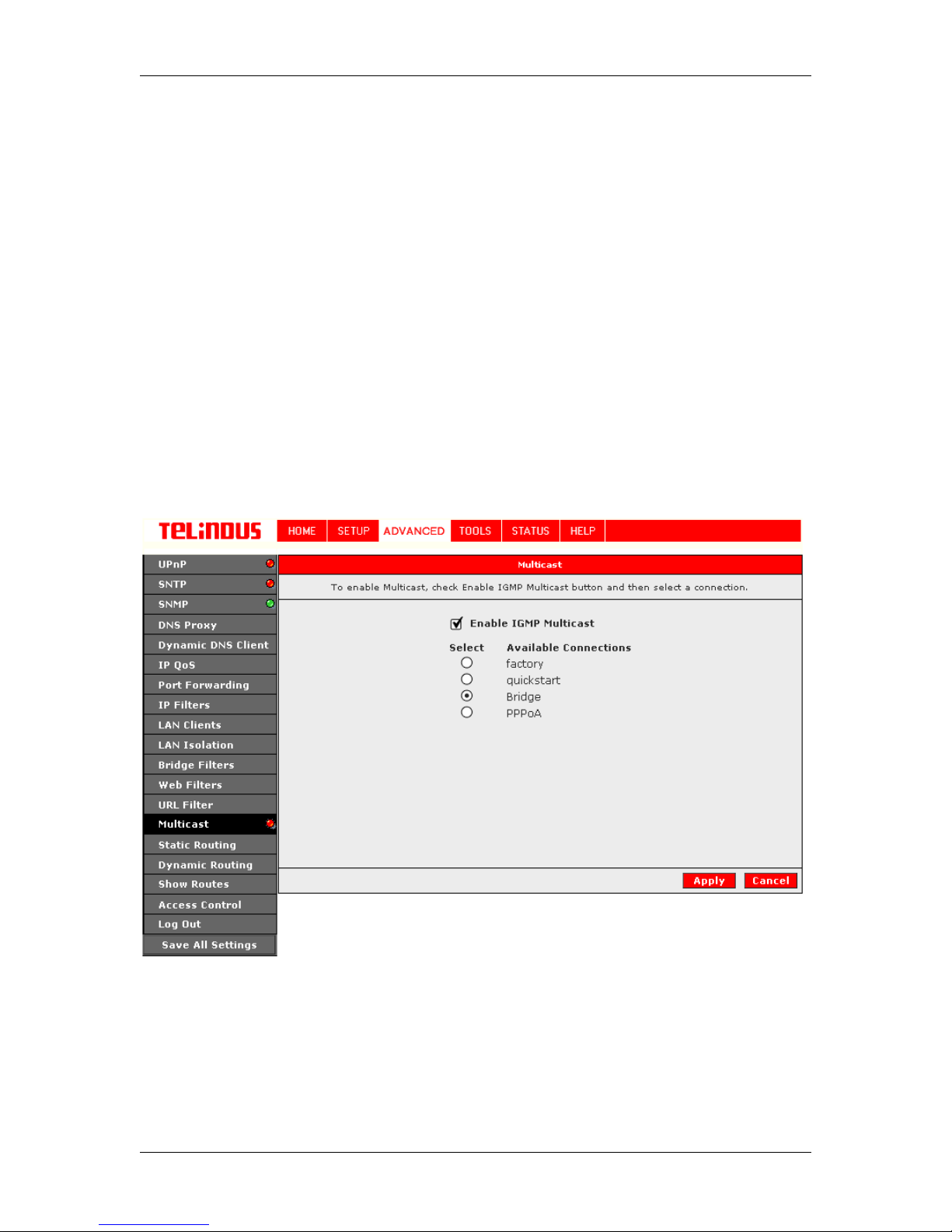
To enable Multicasting, click on Advanced and under Advanced, select Muliticast. Figure 29
illustrates a typical Multicast configuration.
The Apply button will temporarily save these settings. To make the change permanent, you need
to click on
All
.
Save All Settings
Version 2.0 Page 39/52 December 2004
Figure 29 (Multicast)
. At the System Commands page under the TOO LS, click on
Save
Page 40
TELINDUS TELINDUS 1130/1131 Web Interface User’s Guide
4.6.15 Static Routing
If the ADSL Router is c onnec ted t o mo re th an o ne net work, you may need t o s et up a st atic rout e
between them. A static route is a pre-defined pathway that network information must travel to
reach a specific host or network. You can use static routing t o allow different I P domain users t o
access the Internet through the ADSL Router.
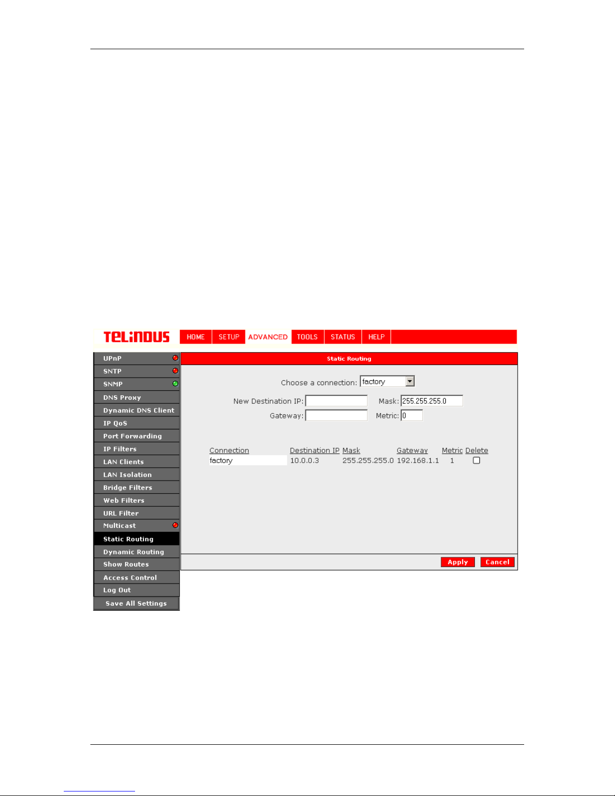
The New Destination I P is the address of the rem ote LAN network or host to which you want to
assign a static route. Enter the IP address of the host for which yo u wish to create a st atic route
here. For a standard Clas s C IP domain, the network add ress is the first three fi elds of the New
Destination IP, while th e las t f ield shou ld be 0. The Subn et Mas k identi fies whi ch po rtio n of an I P
address is the network portion, and whic h portion is the host port ion. For a full Class C S ubnet,
the Subnet Mask is 255. 255.255.0. The Gateway IP address shoul d be the IP address of the
gateway device that allows for contact between the Gateway and the remote network or host.
The Hop Count determines the maximum number of steps between network nodes that data
packets will travel. A node is any device on the network (such as a router or switch)
To enable Static Routing, from the Home s creen, click ADVANCED and select Static Routing.
Figure 30 illustrates a typical Static Route.
The Apply button will temporarily save these settings. To make the change permanent, you need
to click on
All
.
Save All Settings
Version 2.0 Page 40/52 December 2004
Figure 30 (Static Routing)
. At the System Commands page under the TOO LS, click on
Save
Page 41
TELINDUS TELINDUS 1130/1131 Web Interface User’s Guide
4.6.16 Dynamic Routing
Dynamic Routing allows the ADSL Router to automatically adjust to physical changes in the
network. The ADS L Router, using the RIP protoc ol, d etermines t he net work pac kets’ rout e bas ed
on the fewest number of hops b et ween t he sou rc e an d t he des t inat ion. Th e RI P prot ocol r eg ul arl y
broadcasts routing information to other ADSL Routers on the network .
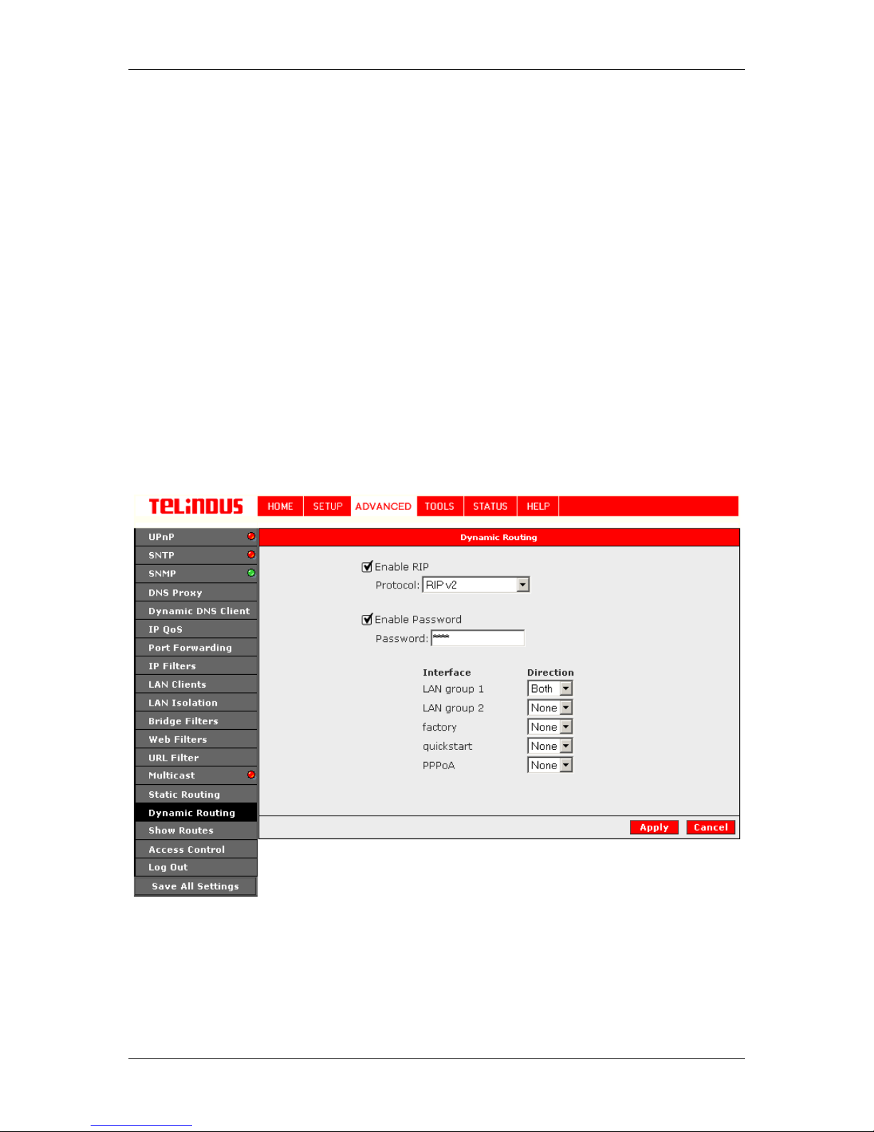
The Direction determines the direction that RIP routes will be updated. Selecting In means that
the ADSL Router will only incorporate received RIP information. Selecting Out means that the
ADSL Router will only send out RIP information. Selecting both means that the ADSL Router will
incorporate received RIP information and send out updated RIP informat ion.
The protocol is dependent upon the entire network. Most networks support Rip v1. If RIP v1 is
selected, routing data will be sent in RIP v1 format. If Rip V2 is selected, routing data will be sent
in RIP v2 format using subnet broadcasting. If Rip V1 Compatible is selected, routing data will be
sent in RIP v2 format using multicasting.
To enable Dynamic Routing, click Advanced and under Advanced, select Dynamic Routing.
Figure 31 illustrates a typical Dynamic Route.
The Apply button will temporarily save these settings. To make the change permanent, you need
to click on
All
.
Save All Settings
Version 2.0 Page 41/52 December 2004
Figure 31 (Dynamic Routing)
. At the System Commands page under the TOO LS, click on
Save
Page 42
TELINDUS TELINDUS 1130/1131 Web Interface User’s Guide
4.6.17 Show Routes
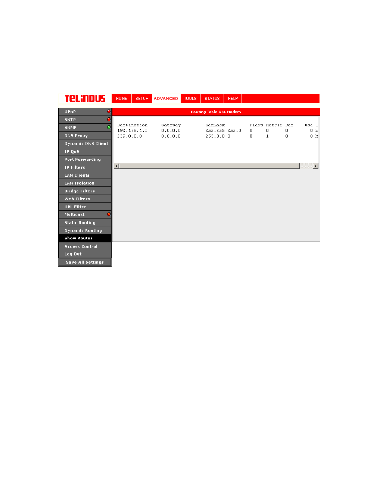
The Sow Routes screen under ADVANCED allows to see both static and dynamic routes
in the Router. See Figure 32 (Routing Table DSL Modem).
Figure 32 (Routing Table DS L Modem)
Version 2.0 Page 42/52 December 2004
Page 43
TELINDUS TELINDUS 1130/1131 Web Interface User’s Guide
4.6.18 Access Control
In the presence of t he f ire wall, ano nym ous I nt e rnet t raf fi c is bloc ked. Us ing the adv anc ed s ec urit y
features, you can redirect this traffic to a dedicated computer and open the access from the
Internet to the ADS L Router's management ports (web, telnet). The ADSL Router's firewall and
NAT services (port forwardi ng, access control) can be disabl ed for all interfaces by un-chec king
the "Enable Firewall and NAT Serv ice" in LAN Setup.
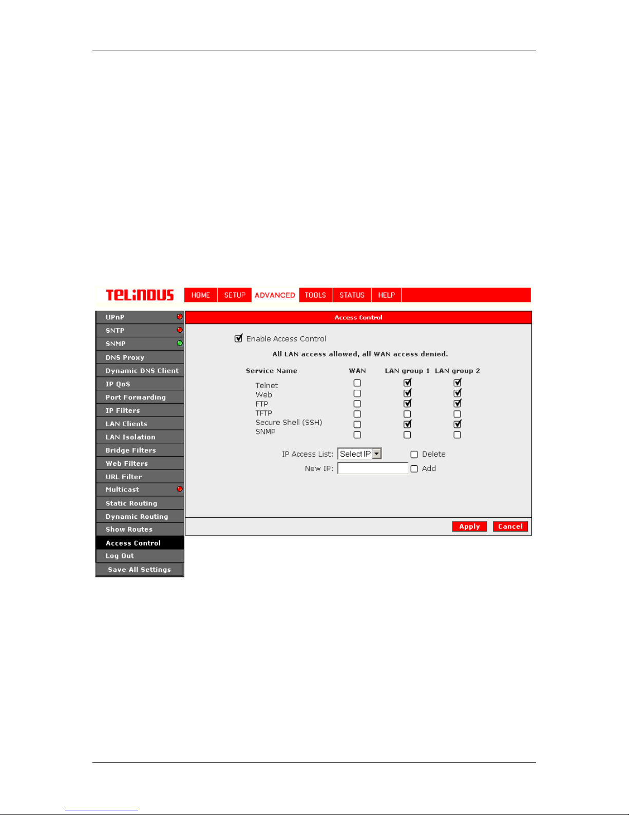
Access control can also be called port blocking. Specific types of traffic that is destined to a
selected LAN IP address can be block ed. To enabl e any of the adv anced sec urity featu res, clic k
ADVANCED, and configure the option under Access Control. A page similar to the portforwarding page appears. An IP address can be added to a rule. All Access Control rules have
precedence over rules that were added via the port-forwarding page. See Figure 33 (Access
Control).
4.6.18.1 Enable Web from WAN
Enabling the Web from WAN on your local network allows Web requests that come from the
Internet to be re-routed t o a Web Server that is on a different s ubnet. This is different that the
Web server rule that is configurable via the port-forwarding page. In this case, the web server is
on a different subnet.
Version 2.0 Page 43/52 December 2004
Figure 33 (Access Control)
Page 44

TELINDUS TELINDUS 1130/1131 Web Interface User’s Guide
4.6.18.2 Enable Remote Telnet
Enabling the Remote Web on your local network allows telnet requests that come from the
Internet to be re-routed t o a telnet Server that is on a diff erent LAN IP subnet. This is diff erent
that the telnet server rul e t hat is c onfig ur abl e v ia t he port -f or wa rdi ng p age. I n t his c as e, t he telne t
server is on a different subnet.
4.6.18.3 Enable Incoming ICMP Ping
Enabling the Incoming Internet C ontr ol M ess age P rot oc ol (ICMP ) P ing will allow Ec ho r eques t s t o
come into the gateway. The gateway will respond with an ICMP Echo response message. The
option allows the DSL provide r or ISP to determine the following:
a. The status of the network.
b. Tracking and isolating ha r d ware and software problems.
c. Tes ting, measuring, and managing networks.
The Apply button will temporarily save these settings. To make the change permanent, you need
to click on
All
.
Save All Settings
. At the System Commands page under the TOO LS, click on
Save
Version 2.0 Page 44/52 December 2004
Page 45

TELINDUS TELINDUS 1130/1131 Web Interface User’s Guide
4.7 TOOLS
The ADSL Router suppo rts a host of tools t hat will al low you t o customiz e and debug y our ADSL
Router.
4.7.1 System Commands
To make the changes permanent you nee d to click on
System Commands
a. Save all: Press this button in order to permanently save the current configuration of the
ADSL Router. If you do re-s tart the system without savi ng your c onf igur ation, the A DSL
Router will revert back to the previously saved configuration.
b.
Restart: Use this button to re-start the system. If you have not saved your
configurations, the ADSL Router will revert back to the previously saved configuration
upon re-starting.
NOTE: Connectivity to the unit will be lost. You can reconnect after the unit reboots.
c.
Restore Defaults: Use this butt on to restore factory default configuration.
NOTE: Connectivity to the unit will be lost. You can reconnect after the unit reboots.
. The following commands are used to configure the gateway:
TOOLS
(at the top of the page) and select
4.7.2 Remote Log
The Remote Log settings allows to enter the address of an external server(s) which can log router
events at different severity levels.
4.7.3 User Management
You can change your ADSL Router’s username and password by clicking on User Management.
From here you can change the login name and password. You can also change the idle timeout;
you will need to log back onto the ADSL Router once the timeout expires.
If you forget your pas sword, you can press and hold the res et to factory defaults button for 10
seconds (or more). The ADSL Router will reset to its fact ory default conf iguration and all cust om
configurations will be lost.
4.7.4 Update Firmware
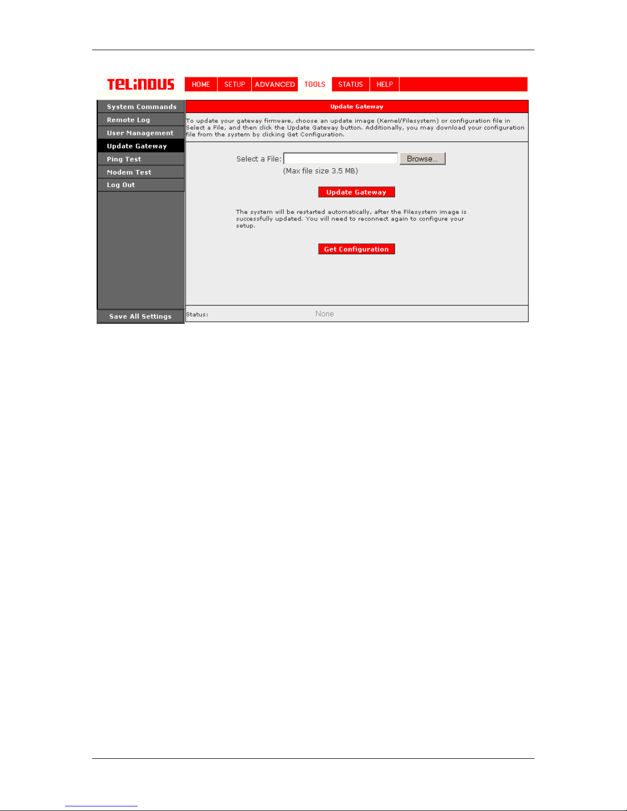
You can remotely upgrad e the ADSL Router’s firmware, c licking on Update Firmware under t he
Tools
page. This will bring up the screen shown in Figure 34. The upgrade file shall be in *.img
format.
To upgrade the firmware, click browse, find the firmware file to download. Make sure this is the
correct file. Click on upgrade firmware (as shown in Figure 34). Once the upgrade is complete
the ADSL Router will reboot. You will need to log back onto the ADSL Router after the firmware
upgrade is completed.
The firmware upgrade s hou ld take about 5 minutes to complete.
Note: Do not remove power from the ADSL Router during the firmware upgrade procedure.
Version 2.0 Page 45/52 December 2004
Page 46
TELINDUS TELINDUS 1130/1131 Web Interface User’s Guide
Figure 34 (Update Firmware)
4.7.5 Ping Test
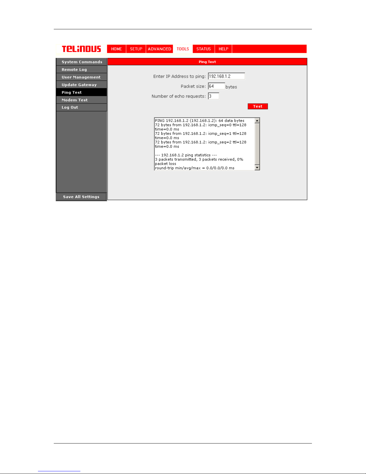
Once you have your ADSL Rout er configured, it is a good idea to make s ure you can ping the
network. You can get t o the Ping page under t he Tools title, by c licking on Ping Tes t. Type the
target address that you want to pin g. If you have y our PC conn ected to the A DSL Router v ia the
default DHCP configurat ion , you shoul d be abl e t o P ing t he net wo rk addres s 1 92. 168.1. 1. I f yo ur
ISP has provided their se rver address you can try t o ping the address. If the pings for both the
WAN and the LAN side complete, and you have the proper proto cols configured, you shoul d be
able to surf the Internet.
By default when you selec t ping test , the ADS L Router will pi ng itself 3 times. If this f irst Ping test
does not pass, the TCP/IP prot ocol is not loaded for some reaso n; you should restart the A DSL
Router.
Version 2.0 Page 46/52 December 2004
Page 47
TELINDUS TELINDUS 1130/1131 Web Interface User’s Guide
Figure 35 (Ping test)
4.7.6 Modem Test
The Modem Test is used to check whether your ADSL Router is properly connected to the WAN
Network. This test may take a few seconds to complete. To perform the test, select your
connection from the list and press the Test button. B efore runni ng this tes t, make sure y ou hav e
a valid DSL link; if the DSL link is not connected, this test will always fail.
Also the DSLAM must support this feature; not all DSLAMs have F4 and F5 support.
Version 2.0 Page 47/52 December 2004
Page 48
TELINDUS TELINDUS 1130/1131 Web Interface User’s Guide
4.8 STATUS
The Status section allows you to v i ew the Status/Statistics of different connections and interfaces
4.8.1 Network Statistics
Select to view the Statis tics of different interfaces - Ethernet/USB/DSL.
4.8.2 Connection Status
Select to view the Status of different connections.
4.8.3 DHCP Clients
Select to view the list of DHCP client s.
4.8.4 Modem Status
Select to view the Status and Statistics of your broadband (DSL) connection.
4.8.5 Product Information
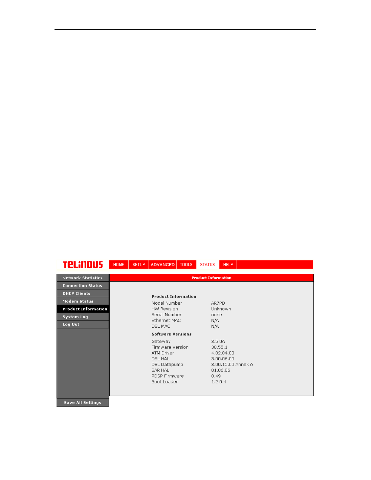
You can display the ADS L Router’s driver and run-time information by going under Status title
and click on Product Information. Figure 36 illustrates the typical product informat ion, which is
provided.
Figure 36 (Product Information)
Version 2.0 Page 48/52 December 2004
Page 49

TELINDUS TELINDUS 1130/1131 Web Interface User’s Guide
4.8.6 System Log
You can display the ADSL Router’s log by going under the Status title, c lick System log. From
here you can view all logged informat ion. Depending upo n the severity level, this logged inf o will
generate log reports to a remote host (if remote logging is enabled).
Version 2.0 Page 49/52 December 2004
Page 50

TELINDUS TELINDUS 1130/1131 Web Interface User’s Guide
5. Appendix A: Troubleshooting
Below is a list of commonly asked questions. Before calling technical support, please look
through these issues to see if they help to solve your problem.
5.1 The ADSL Router is not functional
1. Check to see that the power LED is green and than the network cables are
installed correctly. Refer to the Quick Start G uide for more details.
2. Check to see that the ETH/LAN and PPP/WAN LEDs are green.
3. Check to see that the DSL LED is green
4. Make sure you are not connecting the USB and t he Ethernet port a t the same
time. You must only use 1 interface at a time.
5. Check the s ettings on your PC. Again, refer t o the easy start guide for more
details
6. Check the ADSL Router’s settings .
7. From your PC, can you PING the ADSL Router? Assuming that the ADSL
Router has DHCP enabled and your PC is on the same subnet as the gateway,
you should be able to PING the gat eway.
8. Can you PING the WAN IP? Your I SP s hould hav e prov ided th e IP add ress of
their server. If you can ping the ADSL Router and your protocols are
configured correctly, you should be able to ping the ISPs network. If you
cannot PING the ISP s network, make sur e you are using t he correct protoc ols
with the correct VPI/VCI values.
9. Make sure NAT is enabled for your connection. If NAT is disabled the ADSL
Router will not route frames correctly (except in Bridge connection).
5.2 I can’t connect to the ADSL Router.
1. Check to see that the power LED is green and that the network cables are
installed correctly; see the easy start guide for more details.
2. Make sure you are not connecting the USB and t he Ethernet port a t the same
time. You must only use 1 interface at a time.
3. Make sure that your PC and the ADSL Router is on the same network
segment. The ADSL Router’s default IP address is 192.168.1.1. If you are
running a Windows based PC, you can open a DOS window and type
IPCONFIG; make sure that the network adapter that is connected to the
gateway is within the same 192.168.1.x subnet.
4. Als o, your PC’s Subnet Mask should match the ga teways subnet mask. The
gateway has a default subnet mask of 255.255.255.0.
5. If this still does not work, press the reset button for 10 seconds. This will place
the gateway into its factory default state. Go through the above procedures
again.
6. Make sure NAT is enabled for your connection. If NAT is disabled the ADSL
Router will not route frames correctly (except in Bridge connection).
Version 2.0 Page 50/52 December 2004
Page 51

TELINDUS TELINDUS 1130/1131 Web Interface User’s Guide
5.3 The DSL Link LED continues to blink but does not go solid
1. This means that the DSL line is trying t o train but for some reaso n it cannot establis h
a valid connection. The main cause of this is that you are too far away from the
central office. Contact your DSL service provider for further assistance.
2. Verify that the phone line is connected dir ectly to the wall and to the line input on the
ADSL Router.
3. Make sure that for ev ery parallel phone line connected to t elephone or fax to install
with a micro filter.
Common Problems and Solutions
5.4 The DSL Link LED is always off
1. Make sure you have DSL service. You should get some kind of information from
your ISP that states that DS L s ervic e is ins talled. Y ou c an us u ally t ell if t he s erv ic e is
installed by listening to the phone line; you wil l hear some high-pitc hed noise. If you
do not hear high-pitched noise, contact your ISP.
2.
Verify that the phone line is conn ected direct ly to the wall an d to the line input on t he
ADSL Router. If t he phone line is connect ed to the phone side of the ADSL Router
or you have a splitter installed on the phone line, the DSL light will not come on.
Version 2.0 Page 51/52 December 2004
Page 52

TELINDUS TELINDUS 1130/1131 Web Interface User’s Guide
6. ADSL Router terms
What is a firewall?
A firewall is protection between t he Internet and your local network. It acts similarly to t he firewall
in your car, protecting the int erior of the car from the engine. Your car's fire wall has very small
opening that allow desired conn ections from the engine into the cabin (gas pe dal connection,
etc), but if something happens t o you r e ngine, you are protected.
The firewall in the ADSL Rout er is very similar. Only the desired c onnections that you allow ar e
passed through the fir ewall. These connections are no rmally originating from the local net work;
such as web browsing, checking your email, downloading a file, and playing a game. However, in
some cases, you can allow incoming connections so that you can run programs like a web serv er.
What is NAT?
NAT stands for Network Addres s Translation. Another name for it is Connection Sharing. What
does this mean? Your ISP provides you wit h a s i ngle network address for you to access the
Internet through. Howeve r, you may have several machines on your local network t hat want to
access the Internet at the same time. The ADSL Router provides NAT funct i onality that converts
your local network addresses t o the single network address provided by your ISP. It keeps track
of all these connections and makes sure that the correct information gets to the c orrec t local
machine.
Occasionally, there are certain programs that don't work well throu gh NAT. Some games, and
some specialty applications hav e a bit of trouble. The ADSL Router contains special functionality
to handle the vast majority of these troublesome programs and games. NAT does cause
problems when you want to run a SERVER though. When running a server, please see the DMZ
section below.
What is a DMZ?
DMZ really stands for Demilitarized Zone. It is a way of separating out part of your local network
so that is more open to the Internet. Suppose that you want to run a web-server, or a game
server. Normal servers like t hese are blocked from working by the NAT funct i onality. The solution
is to "isolate" the single local computer into a DMZ . This makes the single computer look like it is
directly on the Internet, and ot hers can access this machine.
Your machine isn't really directly connected to the Internet, and it really has an internal local
network address. When you prov ide the s ervers net work addr ess to ot hers, you must prov ide the
address of the ADSL Router. The ADSL Router "fakes" the connecti on to your machine.
You should use the DMZ when you want to run a server that others will access from the Internet.
Internal programs and servers (like print servers, etc) should NOT be connected to the DMZ
What is a Gateway?
The Internet is so large that a single network cannot handle all of the traffic and still deliver a
reasonable level of service. T o overcome this limit ation, the net work is broken down into smalle r
segments or subnets that can deliver good performance f or the stations attached to that segment.
This segmentation solves the p roblem of supporting a large number of stations, but introduces
the problem of getting traff ic from one subnet to another.
To accomplish this, devices called routers or gateways are placed between segments. If a
machine wishes to contact another device on the same segment, it transmits to that station
directly using a simple discovery technique. If the target station does not exist on the same
segment as the source station, then the source actually has no idea how to get to the target.
One of the configuration parameters transmitted to each network devic e is its default gateway.
This address is configured by t he network administrators and it i nforms each personal compute r
or other network device where to send data if the target station does not reside on the same
subnet as the source. If your machine can reach all stations on the same subnet (usually a
building or a sector within a building), but cannot communicate out side of this area, it is usually
because of an incorrectly c onfigured default gateway.
Version 2.0 Page 52/52 December 2004
 Loading...