

Page 1

USER’S GUIDE
Telindus Technical Publications - Geldenaaksebaan 335 - B-3001 Leuven Belgium - Tel. +32 16 382011
1 120/1121 ADSL Router
Version: 6.0
USER’S GUIDE
Page 2

II User’s Guide
Copyright Notice
Copyright Notice
The information and descriptions contained in this publication are the property of
Telindus. Such information and descript ions must not be copie d or rep roduced by a ny
means, or disseminated or distributed without the express prior written permission of
Telindus.
This publication could include technical inaccuracies or typographical errors, for which
Telindus never can or shall be held liable. Changes are made periodically to the
information herein; these changes will be incorporated in new editions of this
publication. Telindus may make improvements and/or changes in the product(s)
described in the publication at any time, without prior notice.
This equipment, for safety and hygiene purposes, complies with the specific
provisions contained in ARAB/RGPT 54 quater 3.1 (RD 20 06 1975, Art 1, Section X,
Accident Prevention Policy).
Version 6.0 March, 2002
©TELiNDUS
Page 3

User’s Guide III
Table of Contents
Table of ContentsTable of Contents
Table of Contents
1. Before You Begin
1.1 Introduction.............................................................................. 5
1.2 Package Includes..................................................................... 5
1.3 Minimum System Requirements ..............................................6
2. HardwareInstallation
2.1 Diagram of the Telindus 1120/1121.......................................... 7
2.2 Hardware Installation .............................................................10
2.3 Setup Instructions ..................................................................10
2.4 Connect to the Ethernet .........................................................11
2.5 Connect to the DSL Interface .............................................. ...12
2.6 Connect to Power ..... ... ....................................... ... ................13
3. Software Installation
3.1 TCP/IP Installation .................................................................15
4. Configuration
4.1 Configuration Using Web GUI ................................................25
4.2 Basic Configuration - SETUP .................................................26
4.3 Basic Configuration - PVCs ...................................................29
4.4 Basic Configuration - LAN ......................................................32
4.5 Basic Configuration - STATUS ...............................................34
4.6 Basic Configuration - DIAGNOSTIC ......................................35
4.7 Advanced Configuration - PORT MAPPING ..........................36
4.8 Advanced Configuration - IP ROUTING ................................38
4.9 Advanced Configuration - IP FILTERING ..............................40
4.10 Advanced Configuration - BRIDGE FILTERING ....................43
4.1 1 Advanced Configuration - UPGRADE ....................................45
Page 4

IV User’s Guide
Table of Contents
5. Troubleshooting
5.1 No SYNC/WAN Link LED Flashing ........................................47
5.2 Cannot Detect the ADSL Router ............................................48
5.3 DSL Service Seems Slow ......................................................48
Appendix A - Glossary
Glossary ...............................................................................................
Appendix B - Reference
FCC Statement ................................................................................53
FCC Part 68 Requirements ..............................................................54
Page 5

Before You Begin 1
This Chapter Includes:
1.1 Introduction........................................................5
1.2 Package Includes................................................5
1.3 Minimum System Requirements .......................6
1.1 Introduction
The Telindus 1120/1121 ADSL Router is the ultimate solution for any
office or home searching for ultra-fast access to the Internet and
remote networks over ADSL. ADSL Router is a stand-alone device
with true plug-and-play capability. It works with any computer using
an Ethernet port.
The purpose of this guide is to help you ease through the installation
process by providing simple step- by-st ep instr uc tio ns in se ttin g up
your ADSL Router. Please read this guide carefully before you start
installing the unit.
1
11
1.2 Package Includes
• Telindus 1120/1121 ADSL Router (x 1)
• AC to AC Power adapter (x 1)
• CD-ROM (x 1) includes:
User’s Guide in PDF format
• RJ-11 to RJ-11 ADSL phone cable (x 1)
• RJ-45 to RJ-45 straight-through Ethernet cable (x 1)
User’s Guide 5
Page 6

Before You Begin
1.3 Minimum System Requirements
• ADSL line
• Microsoft Windows 98 or later version
• 166 MHz Pentium or equivalent processor
• 16 MB RAM or more
• 170 MB available free hard disk space before installation
• 28.8k or faster modem (optional for dial-up access)
• Available 10BaseT Ethernet or USB port on the main computer
• CD-ROM Drive
6 User’s Guide
Page 7
Hardware
Installation 2
This Chapter Includes:
2.1 Diagram of the Telindus 1120/1121...................7
2.2 Hardware Installation.......................................10
2.2 Hardware Installation.......................................10
2.3 Setup Instructions ............................................10
2.4 Connect to the Ethernet....................................11
2.5 Connect to the DSL Interface ..........................12
2.6 Connect to Power.............................................13
2.6 Connect to Power.............................................13
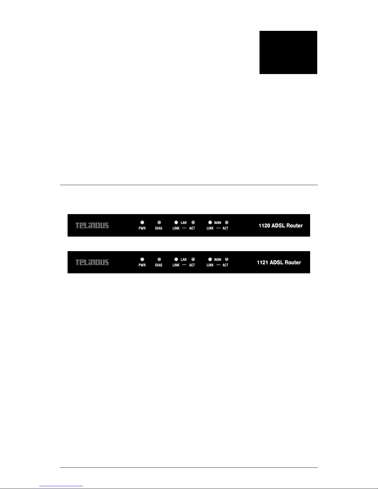
2.1 Diagram of the Telindus 1120/1121
Front Panel Interfaces
2
22
Figure 2.1 Telindus 1120 ADSL Router
Figure 2.2 Telindus 1121 ADSL Router
PWR -- Power
A green PWR LED is ON when power is supplied to the NDS.
DIAG -- Diagnostic
The yellow DIAG LED indicates that the ADSL Router is in a selfdiagnostic mode during boot-up. Once the ADSL Router boots up
successfully, the DIAG LED stops flashing and remains off. If there is
a software malfunction or a problem with the ADSL Router, the DIAG
LED will remain on.
LAN LINK -- Local Area Network (Ethernet)
The green LAN LINK LED displays the 10BaseT Etherne t connection
between ADSL Router and your Ethernet network. The gr een LED is
on and remains solid if there is a valid link.
LAN ACT (Activity) -- Local Area Network (Ethernet)
A flashing yellow LED indicates Ethernet dat a activity between the PC
User’s Guide 7
Page 8

Hardware Installation
and the ADSL Router. The LED flashes when there is data activity on
this port.
8 User’s Guide
Page 9

Hardware Installation
WAN LINK -- Wide Area Network Link
The green W AN LINK LED displays the 10Ba seT Ethernet connection
between the ADSL Router and the remote DSL network. The WAN
LED is on and remains solid if there is a valid link.
WAN ACT (Activity) -- Wide Area Network Activity
A flashing yellow WAN ACT LED indicates data activity between the
remote DSL network and the ADSL Router unit. The LED flashes
when there is data activity on this port.
Back Panel Interface
Figure 2.3 Back Panel Interface
DSL
The ADSL interface connects the ADSL Router to an ADSL line.
POWER
The power interface connects to the power adapter.
ETHERNET
The Ethernet interface connects the ADSL Router to a 10BaseT
network.
User’s Guide 9
Page 10

Hardware Installation
2.2 Hardware Installation
CAUTION!!! Turn off all electronic devices, including your personal
computer, before you begin to connect and disconnect cables.
Personal Safety
• In case of emergency, locate the closest electricity power-off
switch.
• Refrain from touching any active wires or terminals.
• Remove jewelry before working on equipment connected to
electricity.
• Keep cables away from walkways.
• Dispose this product in accordance with national laws and
regulations.
Product Handling
• Keep ventilation slots clear.
• Operate in a clean and dust-free location.
• Cables must be attached to the correct interfaces; to do
otherwise may result in damaging the ADSL Router or produce
hazardous voltage.
• Do not operate or store the product in an environment that
surpasses temperature or humidity specifications.
2.3 Setup Instructions
• Choose a location for the Router close to a power outlet and a
nearby telephone outlet. In addi tion, select a convenient
location that does not experien ce too much foot traffic and is
away from sunlight.
• The optimum spot to place the Router is on a level surface –
such as a desktop, shelf, or table.
• Place the Router on the predet ermined surf ace, so you can see
the back panel for accessible cable connection.
10 User’s Guide
Page 11
Hardware Installation
2.4 Connect to the Ethernet
Step 1. Locate your Ethernet cable (included).
Step 2. Attach the Ethernet cable to the ETHERNET port of your
Router.
Step 3. Plug in the loose end of the Ethernet cable to your Ethernet
network
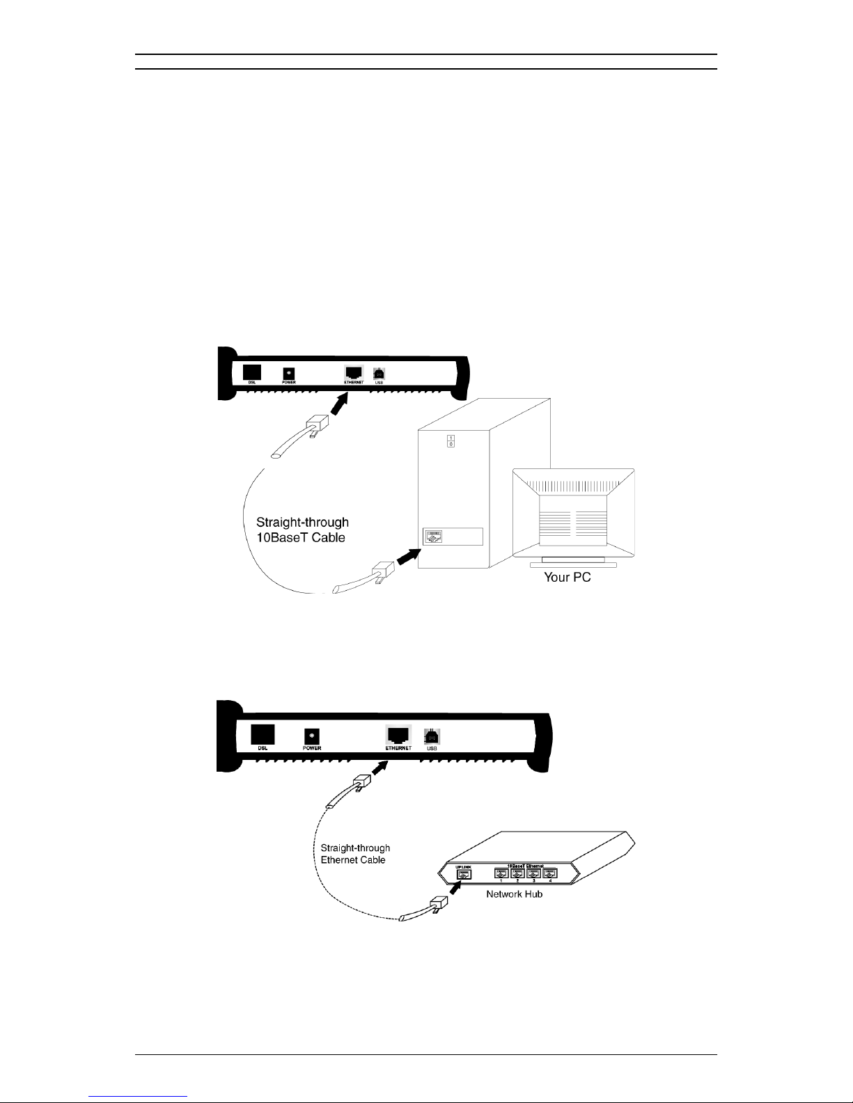
You have 3 options to connect to the Ethernet depending on your
network environment:
Option 1. Connecting to a single PC: Attach the included straight-
through Ethernet cable to the Ethernet port on a PC.
Figure 2.4 Connecting to an Ethernet Port on a PC
Option 2. Connecting to a network hub with uplink port
available: Attach the included straight-through Ethernet
cable to the uplink port on a hub.
Figure 2.5 Connecting to an Uplink P ort on a Network Hub
User’s Guide 11
Page 12
Hardware Installation
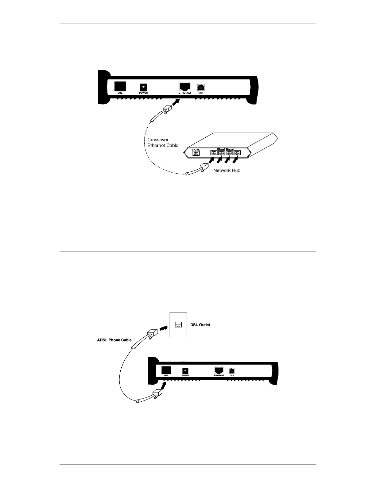
Option 3. Connecting to a network hub with non-uplink port
available: If the uplink port is unavailable, then you can
use a crossover Ethernet cable (Not included) and attach
it to the non-uplink ports on a hub.
Figure 2.6 Connecting to a Non-Uplink Port on a Network
Hub
Step 4. Once the Router is powered on, the LAN LINK LED on the
front panel should lit green to indicate a valid Ethernet
connection. If the LAN LINK LED is not lit, repeat steps 1
through 3 above.
2.5 Connect to the DSL Interface
Step 1. Plug the RJ-11 connector end of the telephone cable (included)
in the DSL port of the Router (RJ-11 to RJ-11).
Step 2. Connect the RJ-11 connector end of the telephone cable to the
DSL outlet on the wall.
Figure 2.7 Connecting to the DSL Interface
Step 3. The WAN LINK LED on the front panel should lit green to
indicate a valid WAN connection. If the WAN LINK LED is not
lit, repeat steps 1 and 2 abo ve.
12 User’s Guide
Page 13
Hardware Installation
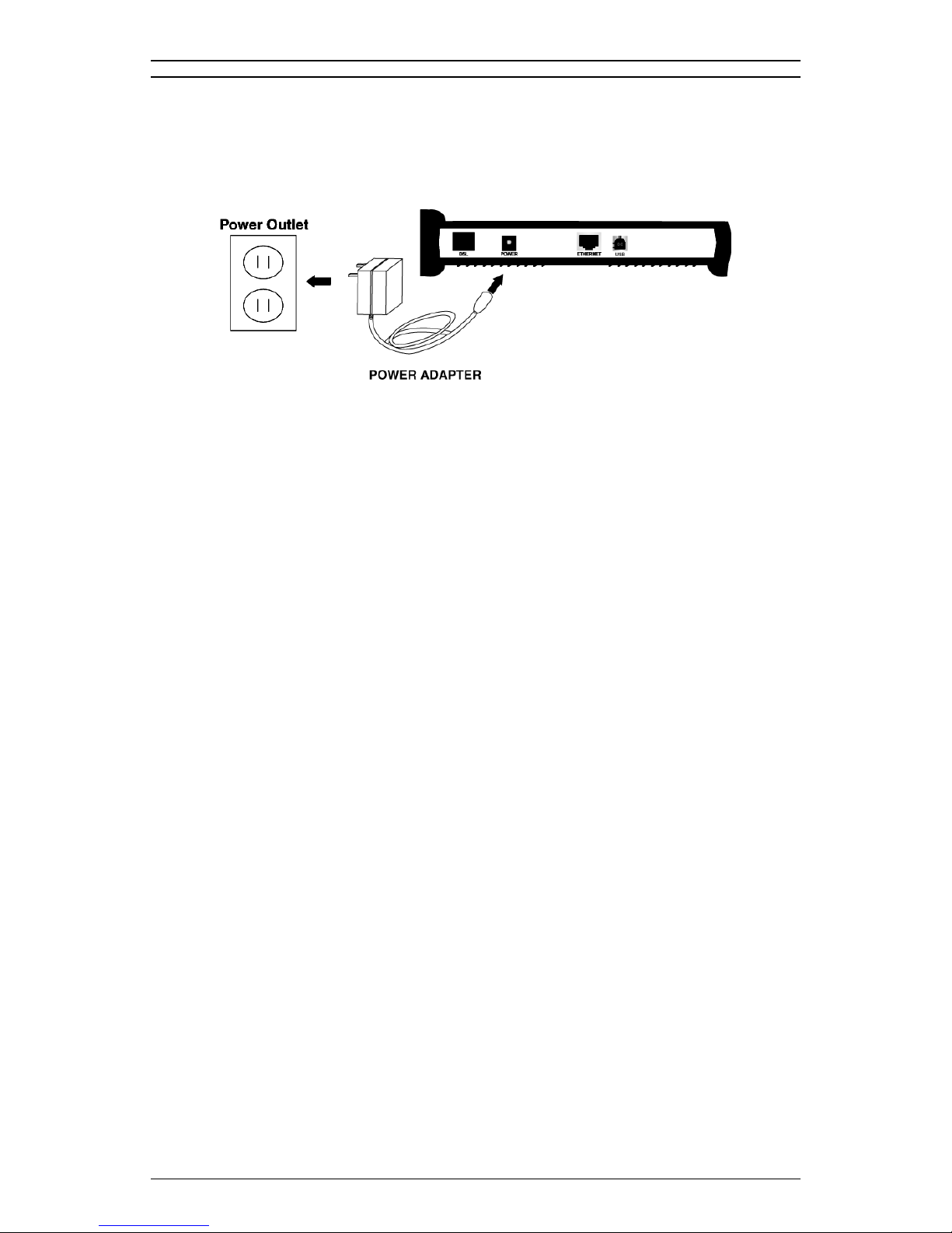
2.6 Connect to Power
Step 1. Plug the power adapter in the POWER port of the Router.
Step 2. Insert the other end of the power adapter t o the power outlet on
the wall.
Figure 2.8 Connecting the Power Supply
Step 3. Once the Router is powered on, the PWR LED on the front
panel should lit green to indicate a valid power connection. If
the PWR LED is not lit, turn off your Router and repeat steps 1
through 3 above.
User’s Guide 13
Page 14

Hardware Installation
14 User’s Guide
Page 15

f
Software
Installation 3
This Chapter Includes:
3.1 TCP/IP Installation ..........................................15
3.1 TCP/IP Inst al lation
You must install a network protocol on each workstation on your LAN
so they can communicate with the Telindus 1120/1121 ADSL Router.
The ADSL Router requires the TCP/IP ne twork protocol. The TCP/IP
Properties window in Windows
workstation’s Ethernet information to the network’s protocol data.
Make sure that each PC on your LAN has TCP/IP available.
Your TCP/IP configuration is solely based on your ISP’s setup. The
following information should be provided by your ISP or company
server:
• IP Address
®
95/98/2000/NT/Me/XP connects the
3
33
• Subnet Mask
• Gateway IP Address
NOTE: The ADSL Router is configured with a default IP address of
192.168.1.1 and subnet mask of 255.255.255.0.
User’s Guide 15
Page 16
Software Installat ion
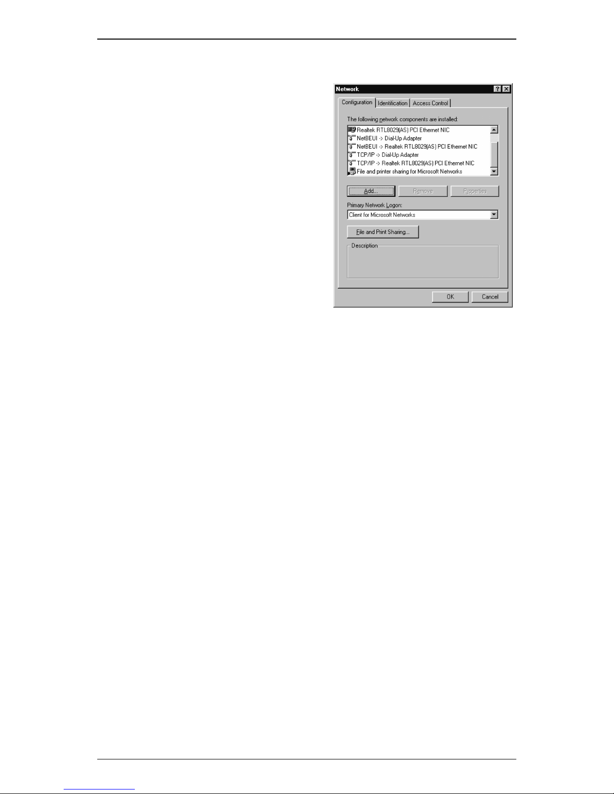
Detecting TCP/IP in Windows® 95/98/Me
Step 1. Click on Start -> Settings ->
Control Panel.
Step 2. Double-click on Network.
Step 3. Click the Configuration tab.
A. If you see TCP/IP listed
under Network
Components, you already
have TCP/IP on your
Windows 95/98/Me.
Proceed to the section
titled “Configuring TCP/IP
in Windows® 95/98/Me.”
B. If you do not see TCP/IP
listed under Network
Components, you do not have TCP/IP on your Windows 95/
98/Me. Proceed to “Installing TCP/IP in Windo ws® 95/98/Me”
in the next section.
16 User’s Guide
Page 17
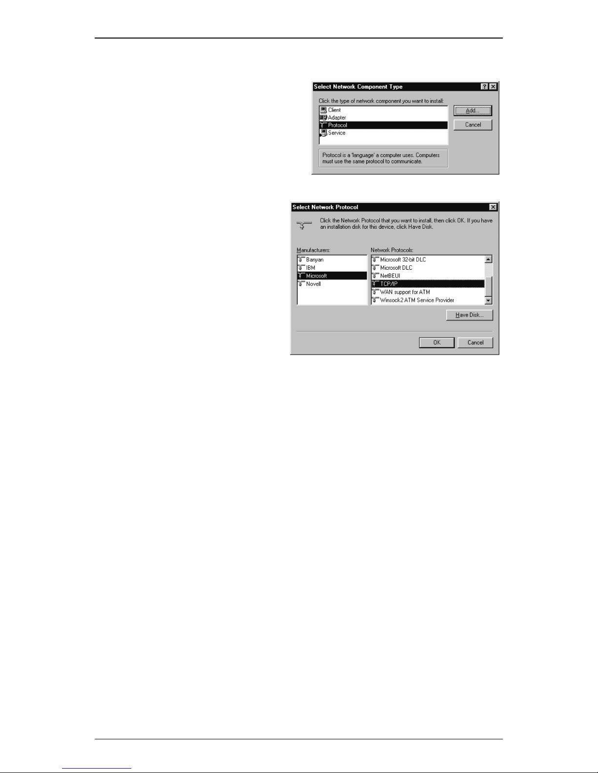
Installing TCP/IP in Windows® 95/98/Me
Step 1. From the Configuration
tab, click Add.
Step 2. Select Protocol and click
Add.
Step 3. Choose Microsoft ->
TCP/IP click OK.
Step 4. Check to see if TCP/IP
is listed under Network
Components.
A. If you do not see
TCP/IP listed under
Network
Components, you
have not installed
TCP/IP. Repeat
steps 1 - 4.
Software Installation
B. If you see TCP/IP listed under Network Components, you
already have TCP/IP on your Windows 95/98/Me. Proceed to
the section titled “Configuring TCP/IP in Windows® 95/98/
Me.”
Configuring TCP/IP in Windows® 95/98/Me
Step 1. From the Configuration tab, select TCP/IP -> XXXX Ethernet
Adapters (“XXXX” is the maker of your Ethernet card) listed
under Network Components and then click Properties.
User’s Guide 17
Page 18
Software Installat ion
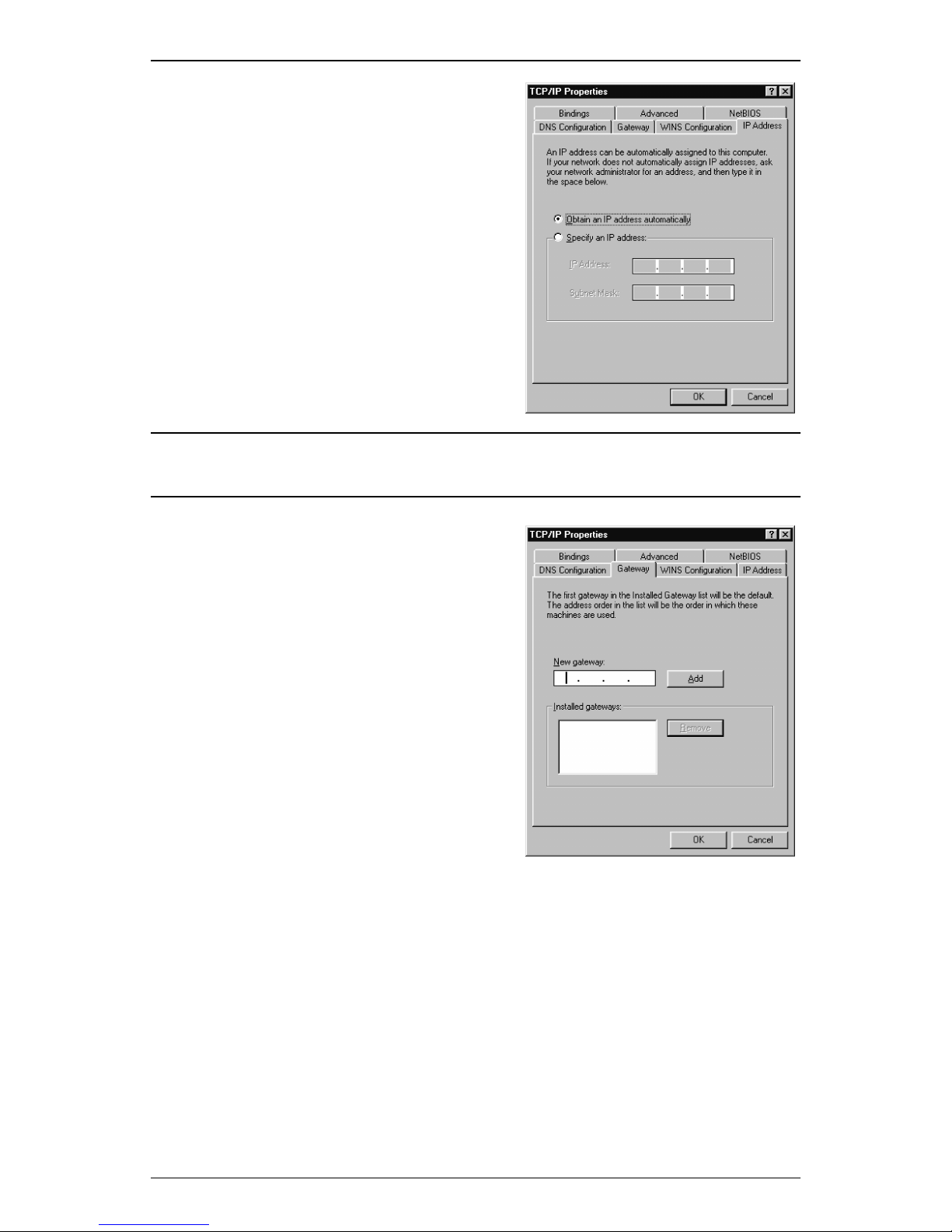
Step 2. Select the IP Address tab.
You now have the option of using
either dynamic or static IP
addressing.
To enable dynamic IP addressing:
Step 1. Click the radio button next to
Obtain an IP Address
automatically.
OPTIONAL: Click the DNS Configuration tab and select Disable DNS. If
you previously entered any parameter s, cl ea r all pr e- ex istin g settin g s.
*
Step 2. Select the Gateway tab.
Step 3. Click Remove to clear all pre-
existing settings.
Step 4. Click OK to exit TCP/IP
Properties window and click
OK to exit the Network
window.
Step 5. If prompted to restart
Windows 95/98/Me, click Yes.
If you are not prompted to
restart Windows 95/98/Me, do
so manually.
* If specifically required by your ISP, you may need to enter DNS information.
18 User’s Guide
Page 19
Software Installation
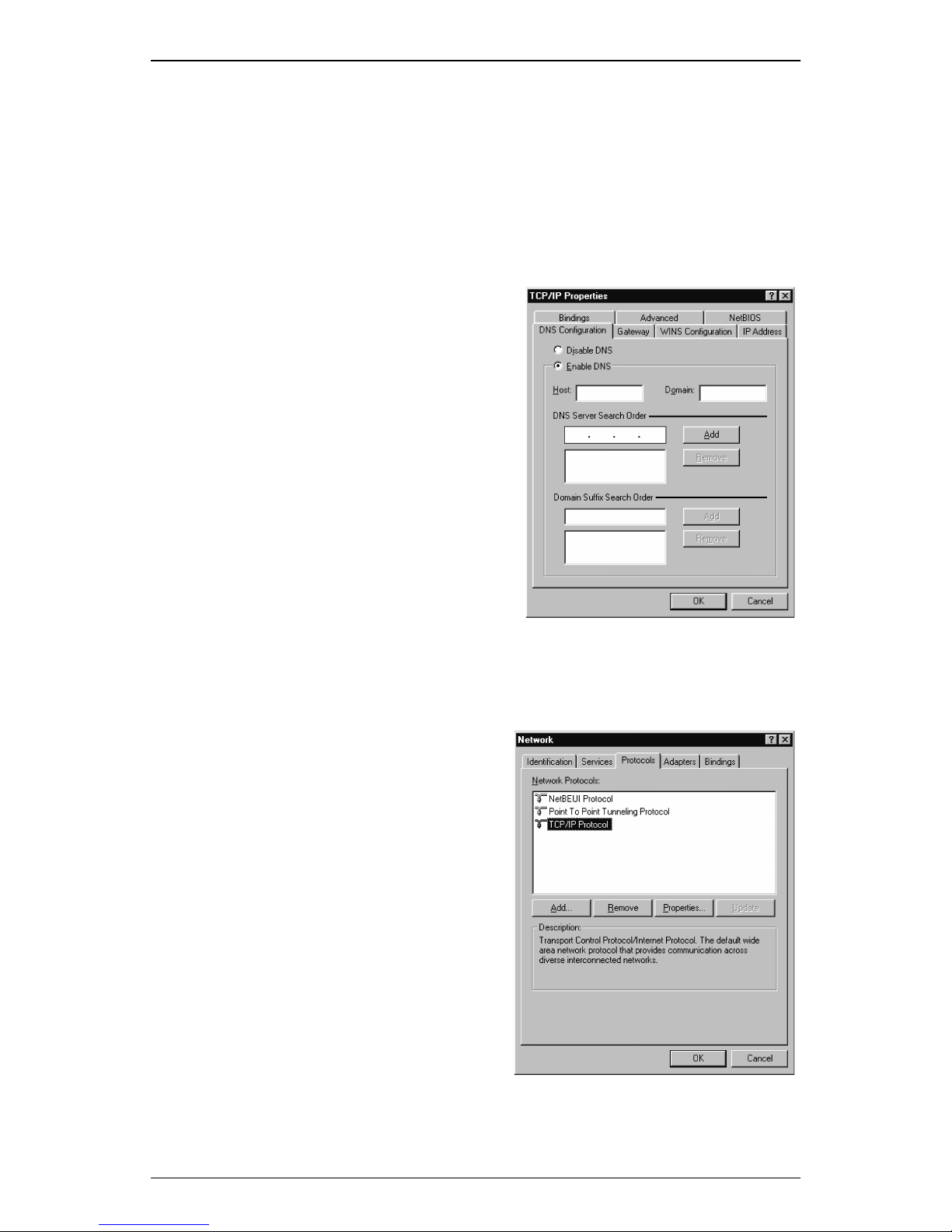
To enable static IP addressing:
Step 1. Click Specify an IP Address.
Step 2. Type the IP Address and Subnet Mask (for your PC).
Step 3. Click the Gateway tab.
Step 4. Type in your Gateway IP Address (the IP address for the
ADSL Router) from your ISP and then click Add.
Step 5. Click the DNS tab. Enter the
Host and Domain names,
and DNS Service Search
Order (for your LAN) and click
Add.
Step 6. Click OK to exit TCP/IP
Properties window.
Step 7. Click OK to exit Network.
Step 8. If prompted to restart
Windows 95/98/Me, click Yes.
If you are not prompted to
restart Windows 95/98/Me ,
please do so manually.
Detecting TCP/IP in Windows® NT
Step 1. Click on Start -> Settings ->
Control Panel.
Step 1. Double-click on Network.
Step 2. Click the Protocols tab.
A. If you see TCP/IP listed
under Network Protocols,
you already have TCP/IP
on your Windows NT.
Proceed to the section
titled “Configuring TCP/IP
in Windows® NT.”
B. If you do not see TCP/IP
listed under Network
Protocols, you do not have
TCP/IP on your Windows NT. Proceed to the next section,
“Installing TCP/IP in Windows® NT.”
User’s Guide 19
Page 20
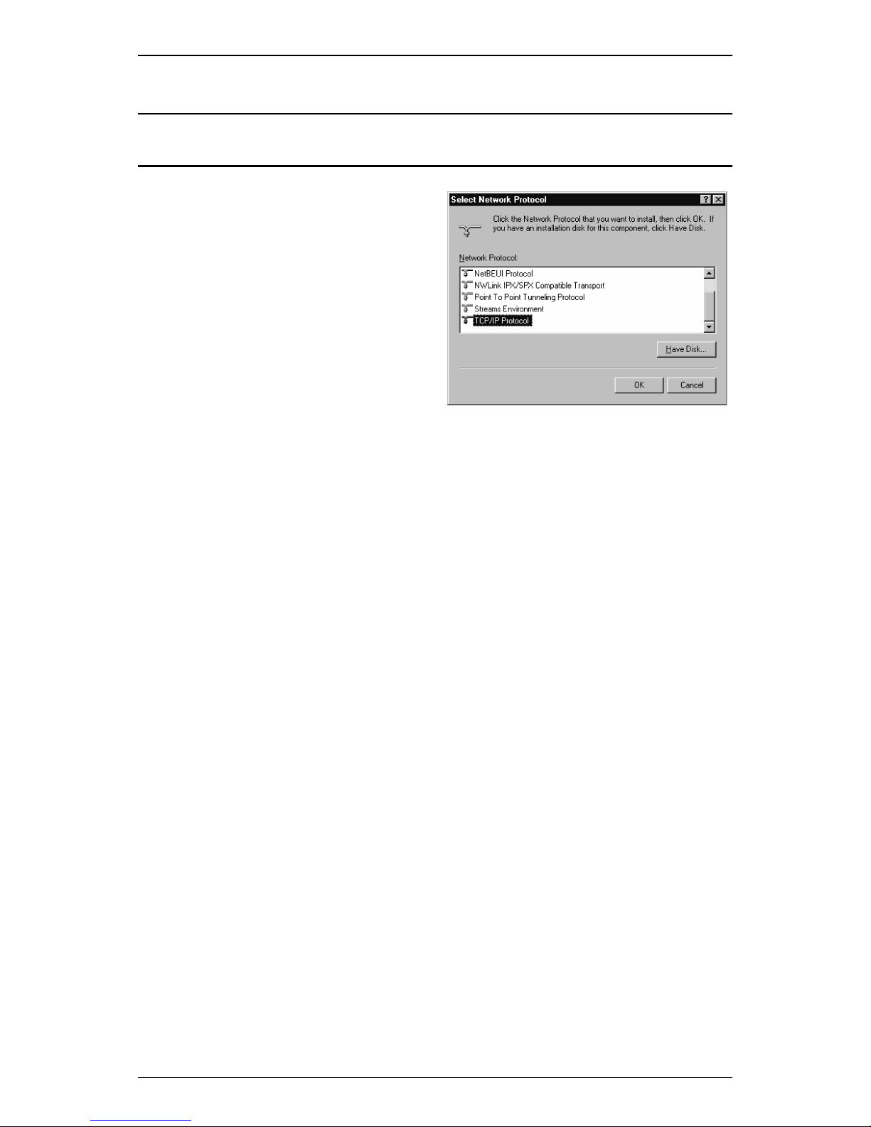
Software Installat ion
Installing TCP/IP in Windows® NT
NOTE: Consult your Network Administrator if you do not have
authorization to change settings for your PC.
Step 1. From the Protocols tab
click Add.
Step 2. Select TCP/IP Protocol
and click OK.
Step 3. Check to verify TCP/IP
Protocol is listed under
Network Protocols, then
click OK.
A. If you do not see TCP/
IP Protocol listed under
Network Protocols, you have not installed TCP/I P. Repeat
steps 1 - 3.
B. If you see TCP/IP Protocol listed under Network Protocols,
then you have successfully installed TCP/I P. Proceed to the
section titled “Configuring TCP/IP in Windows® NT.”
Configuring TCP/IP in Windows® NT
Step 1. From the Protocols tab, select TCP/IP Protocol and click
Properties.
Step 2. Select the IP Address tab.
You now have the option of using either dynamic or static IP addressing.
20 User’s Guide
Page 21
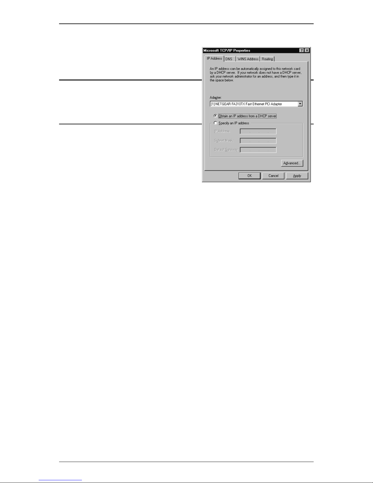
To enable dynamic IP addressing:
Step 1. Click the radio button next to
Obtain an IP Address from
DHCP Server.
OPTIONAL: Click the DNS tab and
select Disable DNS. If you previously
entered any parameters, clear all pre-
existing settings.
*
Step 2. Click OK to exit Network
Properties window.
To enable static addressing:
Step 1. Click the radio button next to
Specify an IP Address and enter the IP Address and Subnet
Mask (for your PC).
Software Installation
Step 2. Click the DNS tab. Enter the Host and Domain names, and
DNS Service Search Order (for your LAN).
Step 3. Click OK to exit Network Properties window.
Configuring TCP/IP in Windows® 2000
Once you have successfully installed a network card onto your PC,
Windows 2000/XP will automatically install Int ernet Protocol (TCP/IP)
by default. All you are left to do is to configure it.
Step 1. Click on Start ->Settings
-> Control Panel -> Network and Dial-up Connections ->
Local Area Connection.
Step 2. In the Local Area Connection Status window, click
Properties.
* If specifically required by your ISP or remote server, you may need to enter DNS informa-
tion.
User’s Guide 21
Page 22
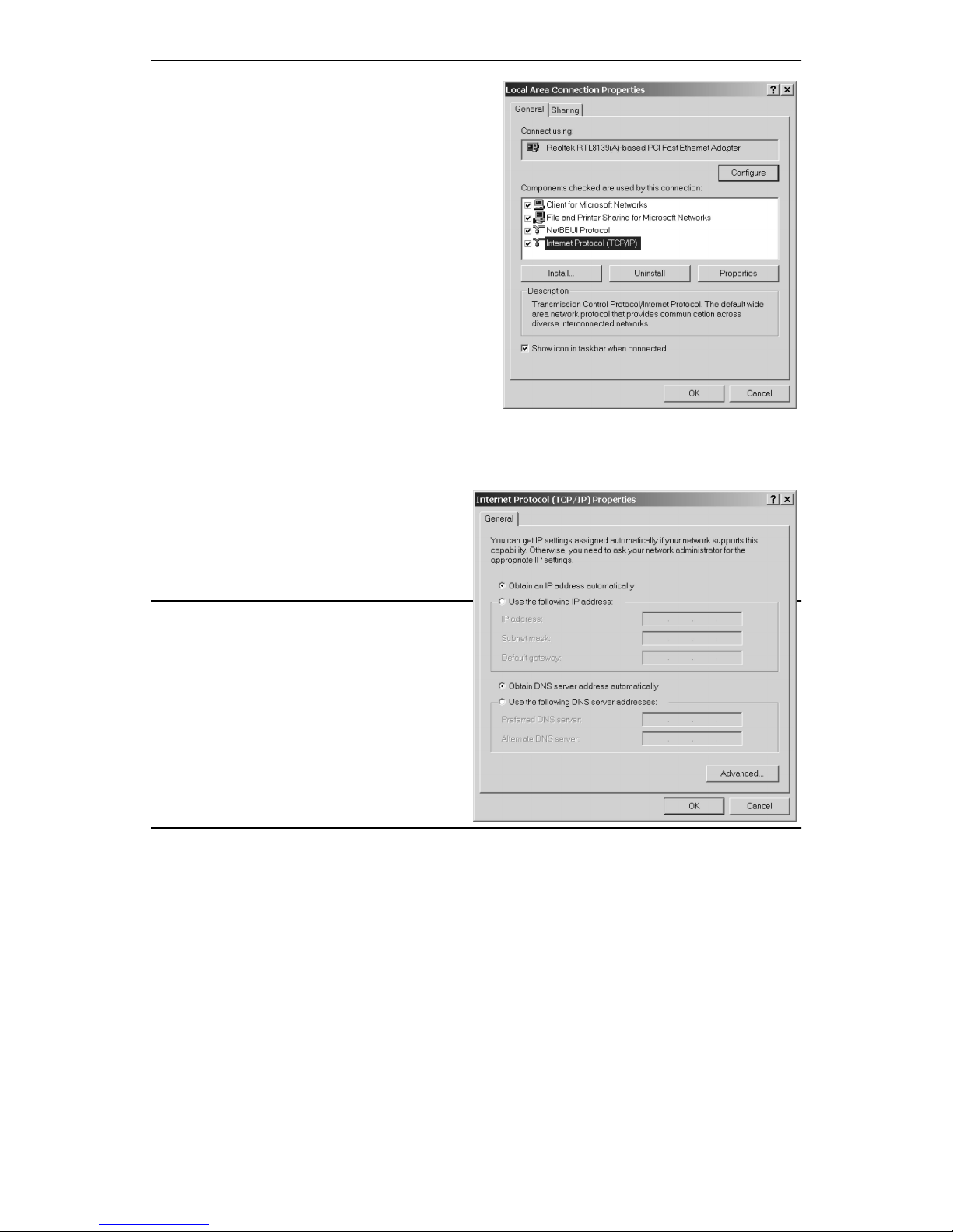
Software Installat ion
Step 3. Under the General tab in
the Local Area
Connection Properties
window, highlight Internet
Protocol (TCP/IP) and
click Properties.
Step 4. From the General tab,
select Internet Protocol
(TCP/IP) and click
Properties.
To enable dynamic IP addressing:
Step 1. Click the radio button
next to Obtain an IP
Address
automatically.
OPTIONAL: You can either click
Obtain DNS server address
automatically or Use the
following DNS server addresses
options. If you choose the Use the
following DNS server addresses
option, then you need to enter the
Preferred and Alternate DNS
server IP addresses.
Step 2. Click OK to exit the Internet Protocol (TCP/IP) Properties
window.
22 User’s Guide
Page 23
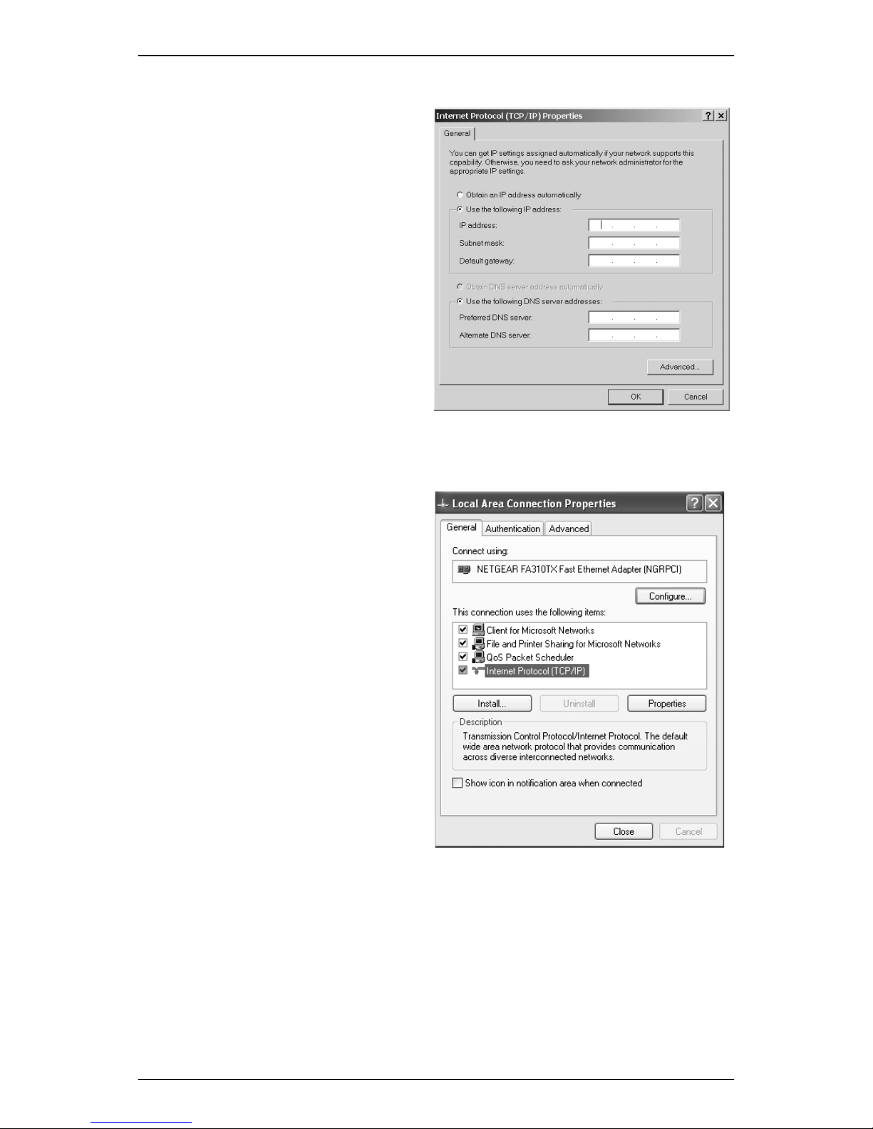
To enable static IP addressing:
Step 1. Click Use the following
IP Address and enter
the IP Address,
Subnet Mask, and
Default Gateway.
Step 2. Enter the Preferred and
Alternate DNS server
IP addresses.
Step 3. Click OK to exit the
Internet Protocol (TCP/
IP) Properties window.
Configuring TCP/IP in Windows XP
Software Installation
Step 1. Click Start -> Control
Panel.
Step 2. In the Control Panel
window, double-click
Network and Internet
Connections.
Step 3. Double-click Network
Connections.
Step 4. Double-click Local
Area Connection.
Step 5. Under the Local Area
Connection Status
window, click
Properties.
Step 6. Under the General
Local Area
Connection Properties window, highlight Internet Protocol
(TCP/IP) and click Properties.
User’s Guide 23
Page 24
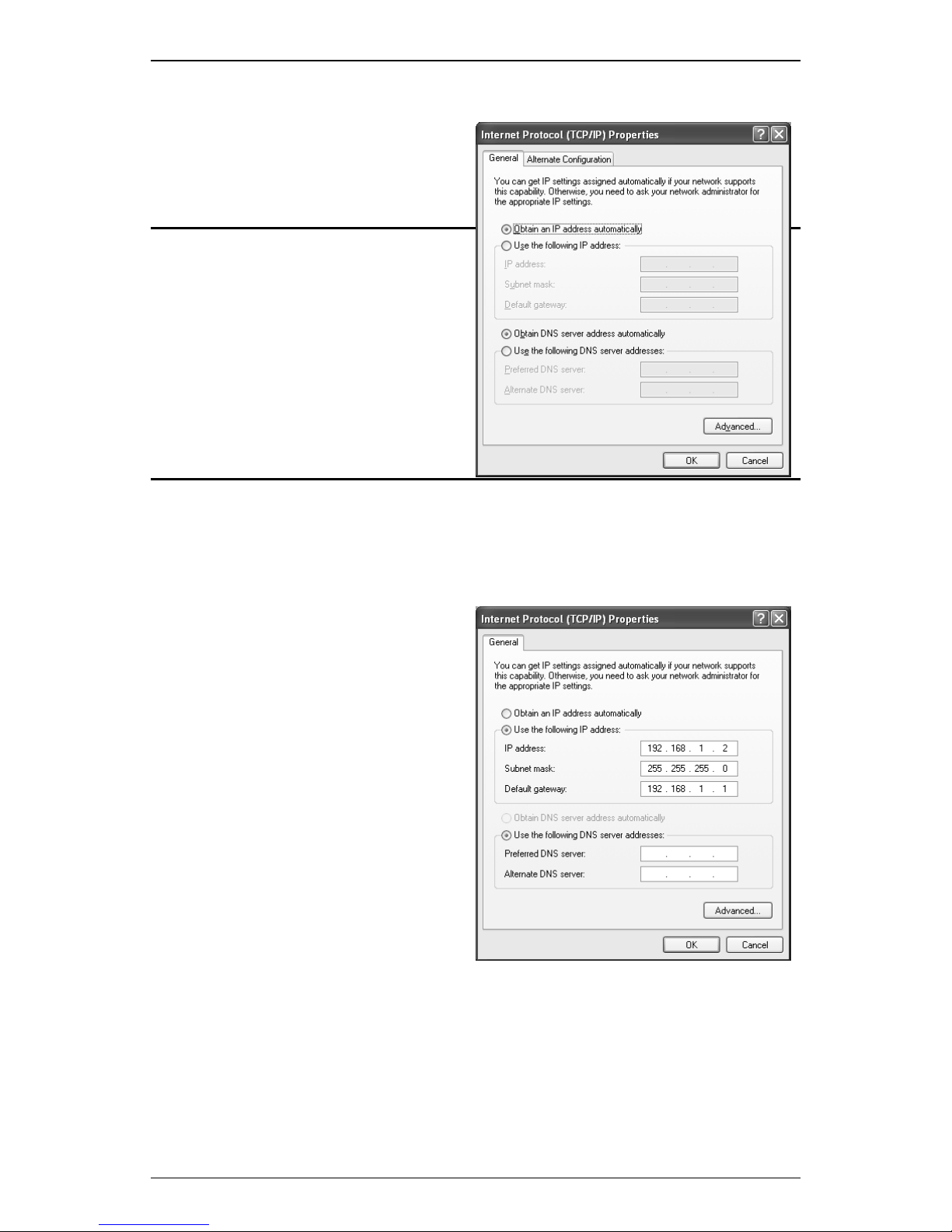
Software Installat ion
To enable dynamic IP addressing:
Step 1. Click the radio button
next to Obtain an IP
Address
automatically.
OPTIONAL: You can either click
Obtain DNS server address
automatically or Use the
following DNS server
addresses options. If you choose
the Use the following DNS
server addresses option, then
you need to enter the Preferred
and Alternate DNS server IP
addresses.
Step 2. Click OK to exit the Internet Protocol (TCP/IP) Properties
window.
To enable static IP addressing:
Step 1. Click Use the
following IP Address
and enter the IP
Address, Subnet
Mask, and Default
Gateway.
Step 2. Enter the Preferred
and Alternate DNS
server IP addresses.
Step 3. Click OK to exit the
Internet Protocol (TCP/
IP) Properties window.
24 User’s Guide
Page 25
Configuration 4
This Chapter Includes:
4.1 Configuration Using Web GUI ........................25
4.2 Basic Configuration - SETUP..........................26
4.3 Basic Configuration - PVCs ............................29
4.4 Basic Configuration - LAN..............................32
4.5 Basic Configuration - STATUS .......................34
4.6 Basic Configuration - DIAGNOSTIC .............35
4.7 Advanced Configuration -
PORT MAPPING ............................................34
4.8 Advanced Configuration - IP ROUTING........38
4.9 Advanced Configuration - IP FILTERING......40
4.10 Advanced Configuration -
BRIDGE FILTERING .....................................41
4.11 Advanced Configuration - UPGRADE............45
4
44
4.1 Configuration Using Web GUI
The Telindus 1120/1121 ADSL Router offers a platform-independent,
HTML-based GUI (graphical user interface) to simplify the setup and
configuration of your ADSL Ro uter using your PC’ s web browser. The
steps below help you configu re your ADSL Router on the LAN using
the web GUI:
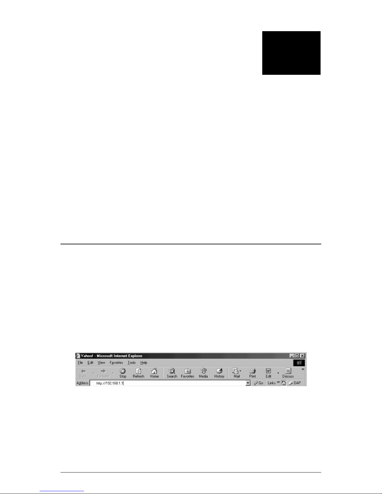
Step 1. Launch a web browser (i.e . Internet Explorer or Netscape
Navigator) from your computer.
Step 2. Enter the default URL http://192.168.1.1 and press Enter.
The web browser may take a couple minute s to log on to your ADSL
Router (TIP: Press Enter or click Go twice may speed up the log-on
process).
User’s Guide 25
Page 26
Configuration
As you proceed with the configuration, you will notice that the ADSL
Router web GUI is divided into two sections:
Basic: Allows you to enter values for a basic
ADSL Router configuration: SETUP,
PVCs,
LAN, STATUS, and DIAGNOSTIC.
Advanced: For users in need of greater control over
the ADSL Router, you can click the
Advanced tab any time and access
these optional sections: PORT
MAPPING, IP ROUTING , IP FIL TERING,
BRIDGE FILTERING and UPGRADE.
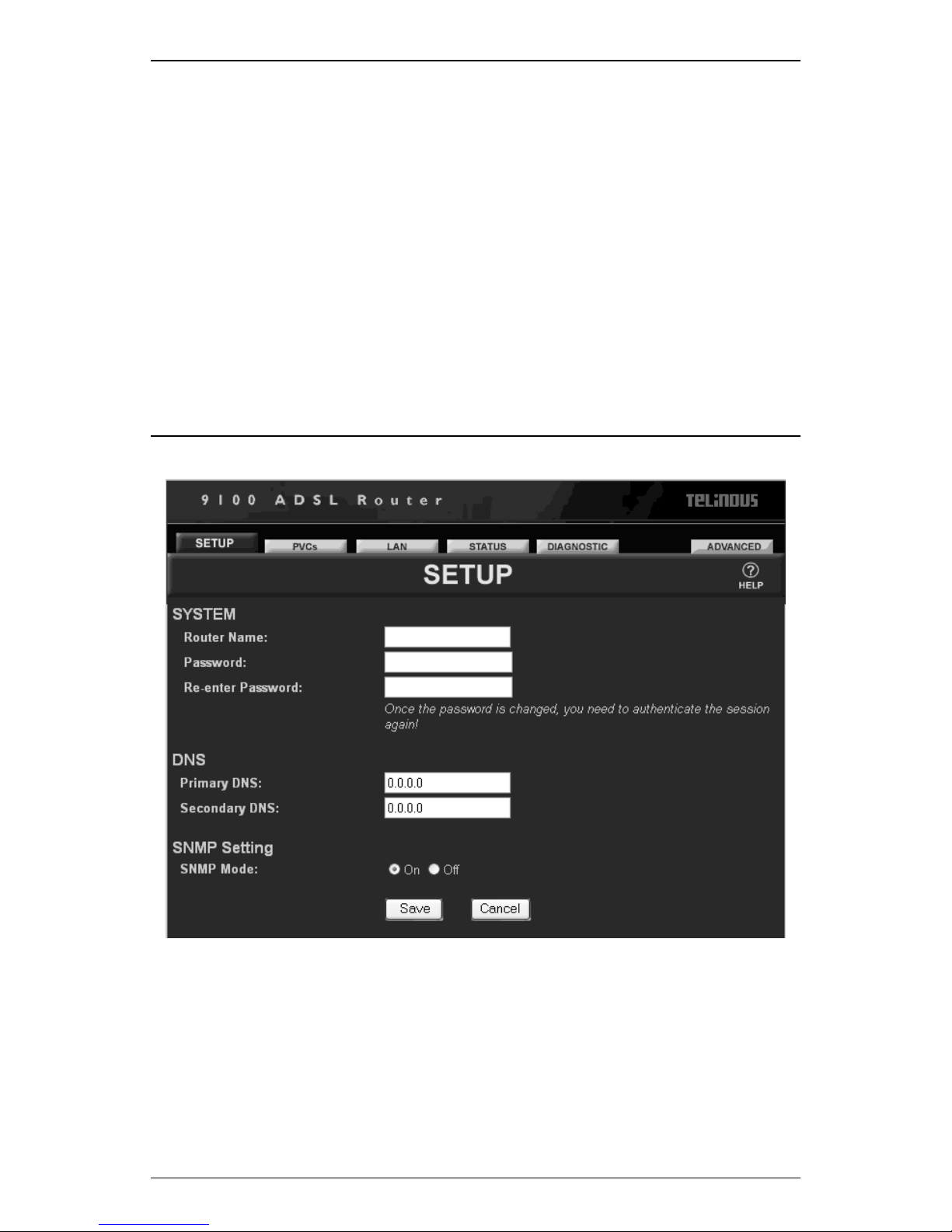
4.2 Basic Configuration - SETUP
A. Click the SETUP tab on the top.
This page allows you to configure the following parameters:
(1) SYSTEM
(2) DNS
The System page allows you to enter a User Name and Password
to ensure maximum administrative security for your ADSL Router.
26 User’s Guide
Page 27

Configuration
User Name: Enter a desired user name here.
Password: This feature provides maximu m se cur i ty
for your ADSL Router by limiting access
to users with the correct password only.
When you type your password, the nam e
will appear as asterixes (****).
Re-enter Password: Enter your password again to ensur e
you have the correct password.
User’s Guide 27
Page 28

Page 29
4.3 Basic Configuration - PV Cs
PVCs Basic Setting
Configuration
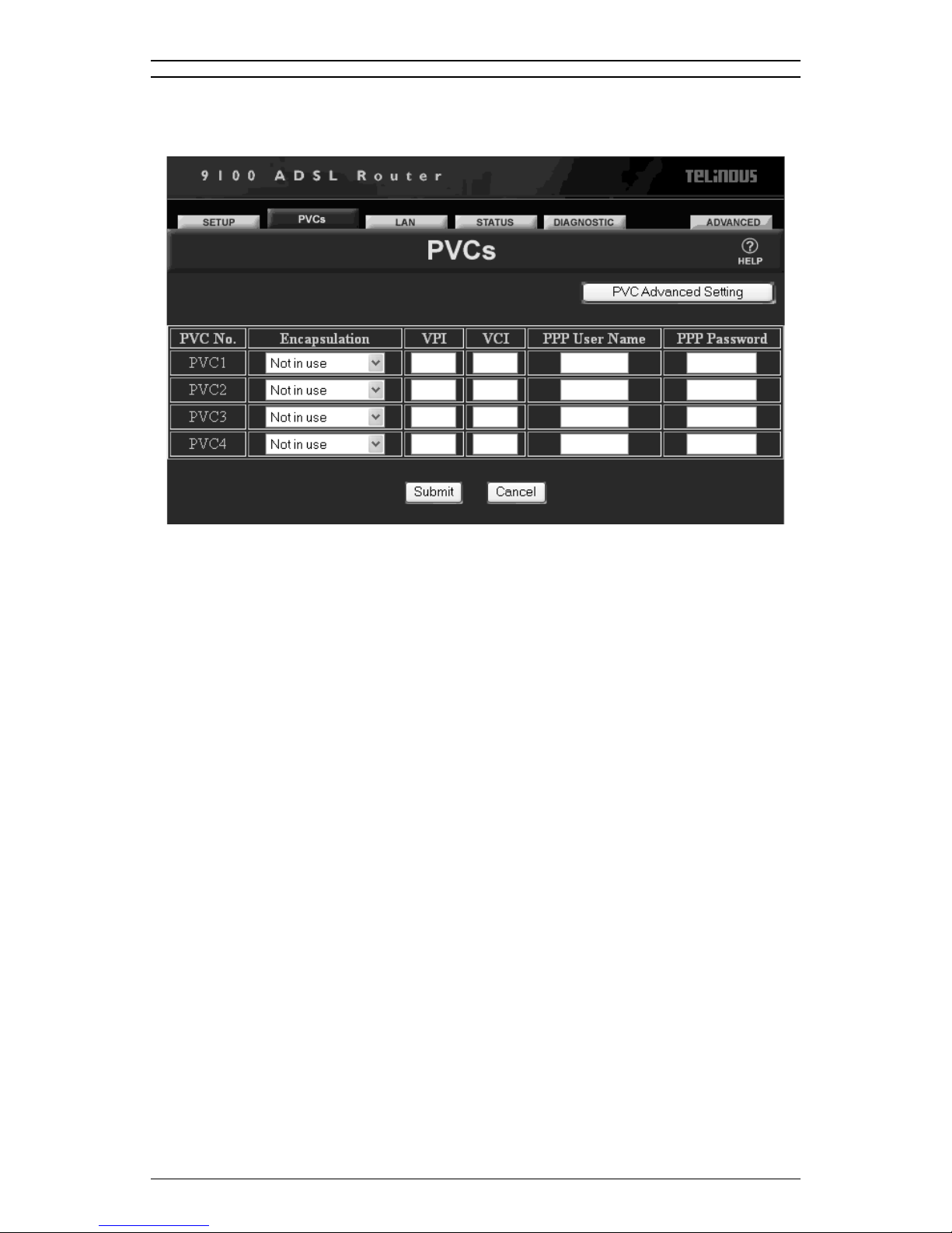
A. Click the PVCs tab on the top.
The PVCs Basic Setting page allows you to configure and enter
PPP User Name and Password for each individual ATM PVC
interface on your ADSL Router:
PVC No.: The ID number that correspo nds to each
ATM PVC interface.
Encapsulation: Allows you to choose the encapsulation
type used at the ATM interface. The
options are SNAP/ IP, VC MUX over
ATM, LLC PPP over ATM, PPP over
ATM, PPP over Ethernet, and SNAP/
Bridge protocols.VPI:A virtual path is a
semi-permanent connection between
endpoints in an ATM network and may
support one or more virtual channels. In
Private Virtual Circuit (PVC) mode, the
Virtual Path Identifier (VPI), which is a
header subfield, is assigned manually
when the ADSL Router is used. Dif ferent
VPI values allow the endpoints to
discriminate between different virtual
connections between ATM nodes.
The minimum and maximum values of
the VPI are 0 and 255, respectively.
User’s Guide 29
Page 30
Configuration
VCI: Each connection in an ATM network is
PPP User Name: The name of the Internet acco unt
PPP Password: The password you use to access your
B. After entering these values, click Submit to send these
characterized by a Virtual Channel
Identifier (VCI). This is a header
subfield that is assigned manually when
ADSL Router is used. A VCI has only
local significance on the link between
ATM nodes. When the connection is
released, the VCI value on the involved
links will be released and can be reused
by other connections.
The minimum and maximum values of
the VCI are 32 and 4095, respectively.
provided by your ISP.
ISP account.
settings to your ADSL Router. To discard these settings, click
Cancel. To further configure advanced settings for your ATM
PVC interface, click the PVC Advanced Settings button.
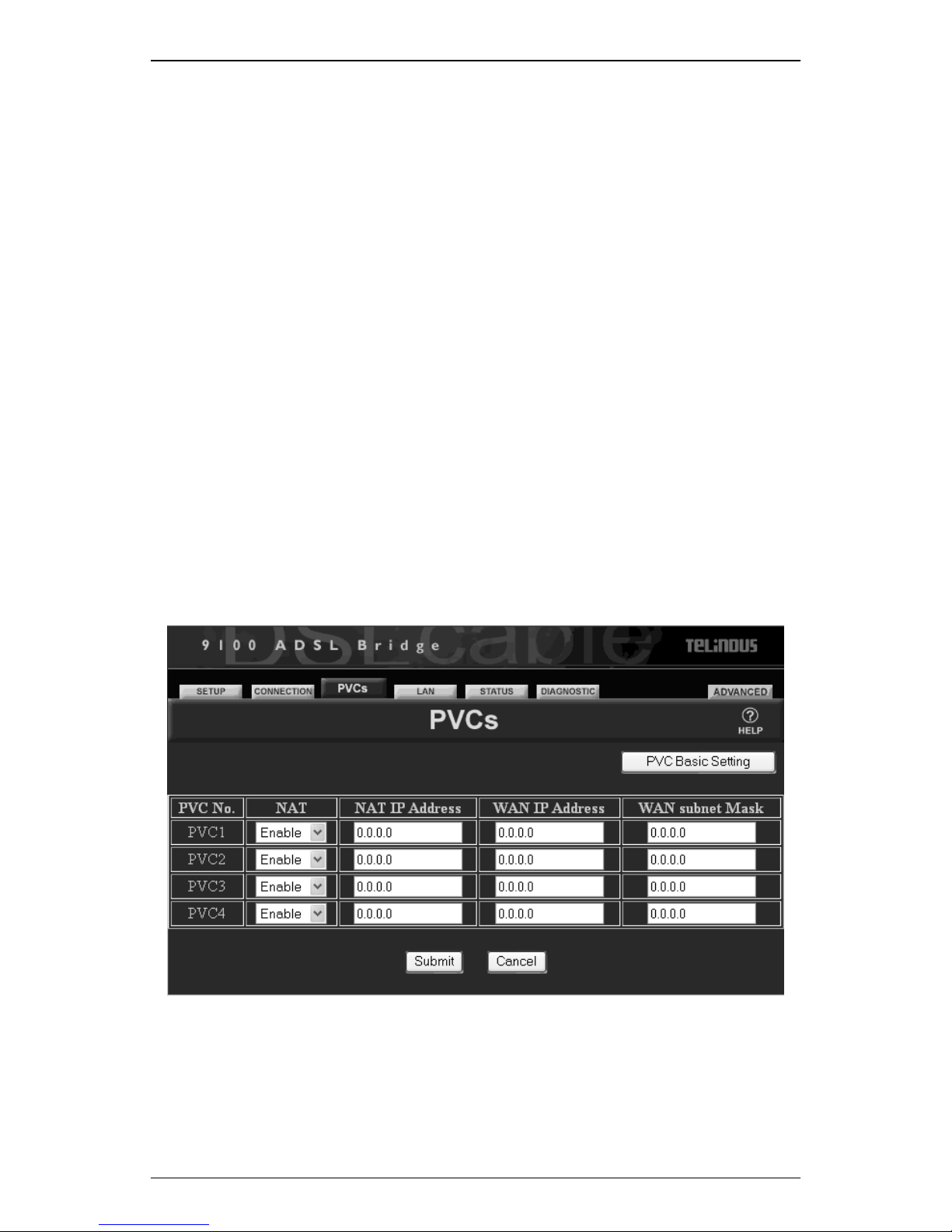
PVCs Advanced Settings
Under the PVCs Advanced Settings page, you can enable or
disable the NAT function on the designated ATM PVC interface. The
Network Address T ranslation functions allows the ADSL Router to
perform IP-sharing, which means multiple PCs on your LAN with
Private IP addresses can share Internet access using one Public I P
30 User’s Guide
Page 31

Configuration
Address.
NAT: Allows you to choose to enable or
disable the NA T function on the specif ied
ATM PVC interface.
NAT IP Address: If you have enabled the NAT function,
then you may need to enter the specified
NAT IP Address.
WAN IP Address: Enter ADSL Router’s WAN IP address
provided by your ISP.
WAN Subnet Mask: Enter ADSL Router’ WAN IP address
provided by your ISP.
A. After entering these values, click Submit to send these
settings to your ADSL Router. To discard these settings, click
Cancel. To return to configuring basic settin gs for yo ur ATM
PVC interface, click the PVC Basic Settings button.
User’s Guide 31
Page 32
Configuration
4.4 Basic Configuration - LAN
A. Click the LAN tab on the top.
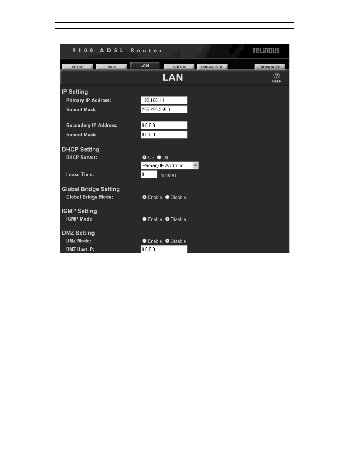
The LAN page allows you to configure the following parameters:
(1) IP Setting
(2) DHCP Setting
(3) Global Bridge Setting
The IP Setting section assigns the IP address of the ADSL Router
unit on your LAN and defines the associated IP subnet.
Primary IP Address: Enter the primary IP address for the L AN
interface.
Subnet Mask: Enter the subnet mask to correspond to
the LAN IP addressyou have entere d
above.
Secondary IP Address: Enter a secondary IP address for the
LAN interface if you have an additional
subnet on the network.
Subnet Mask: Enter an additional subnet mask to
32 User’s Guide
Page 33

Configuration
correspond to the Primary LAN IP
address you have entered.
NOTE: Remember, when you assign these parameters you must make
sure your PC and the ADSL Router are in the same subnet.
The DHCP Setting section allows you to enable or disable the use of
DHCP for a Multiple IP Address Account. DHCP, Dynamic Host
Configuration Protocol, dynamically assigns (leases) Private IP
Addresses to devices on a network. With dynamic addressing, a
device can be assigned an IP address each time it connects to the
network.
DHCP simplifies network administration because the ADSL Router
keeps track of IP addresses rather than requiring an administrator to
manage the task. Th is means that a new computer can be added to a
network without the hassle of manually assigning it an IP Address.
DHCP Server: Allows you to enable or disable the
DHCP function on your ADSL Router.
Lease Time: The amount of time that a network
device can have (lease) a Private IP
Address before the ADSL Router makes
the address available for re-assignment.
The Global Bridge Se tt ing section allows you to manually enable or
disable the Ethernet bridge, thus allowin g data originated from the
DSL line to be transferred to the Ethernet.
Global Bridge Mode: Allows you to enable or disable the
Ethernet bridge function.
B. After entering these values, click Submit to send these
settings to your ADSL Router. To discard these settings, click
Cancel.
User’s Guide 33
Page 34
Configuration
4.5 Basic Configuration - STATUS
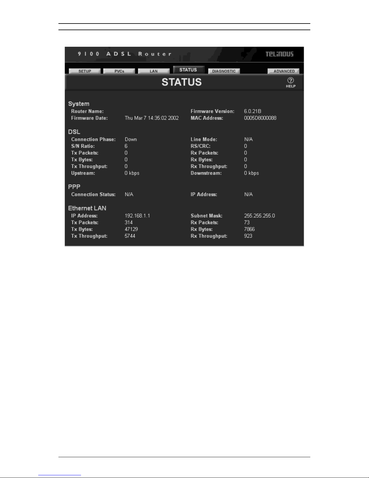
A. Click the STATUS tab on the top.
The Status page collects information from various functions and
operations of your ADSL Router and disp lays all t he inf orma tio n on a
single page for your convenience. Viewing the overall status of your
system makes it easier for you to monito r, troubleshoot, and reboot
your ADSL Router if necessary.
At a single glance, you will find the following ADSL Router
information:
1. System: Router Name, Firmware Version, Firmware Date, and
MAC Address.
2. DSL: Connection Phase, Line Mode, S/N Ratio, RS/CRC,
Transmitted (TX) and Received (RX) DSL Packets, Bytes, and
Throughput, Upstream and Downstream rates.
3. PPP: PPP Connection Status and IP Address.
4. Ethernet LAN: LAN IP Address, Subnet Mask, and Transmitted
(TX) and Received (RX) Ethernet Packets, Bytes, and
Throughput.
34 User’s Guide
Page 35

Configuration
4.6 Basic Configuration - DIAGNOSTIC
A. Click the DIAGNOSTIC tab on the top
The Diagnostic page allows you to run a self-diagnostic feature on
the ADSL Router and check to see if all interfG8hs.6(G8h a)-1(r)e worG8hin-1(ge on )T*82 g-070039 Tc0 Tp-5(urt)4pgnos9lyic
User’s Guide 35
Page 36
Configuration
4.7 Advanced Configuration - PORT MAPPING
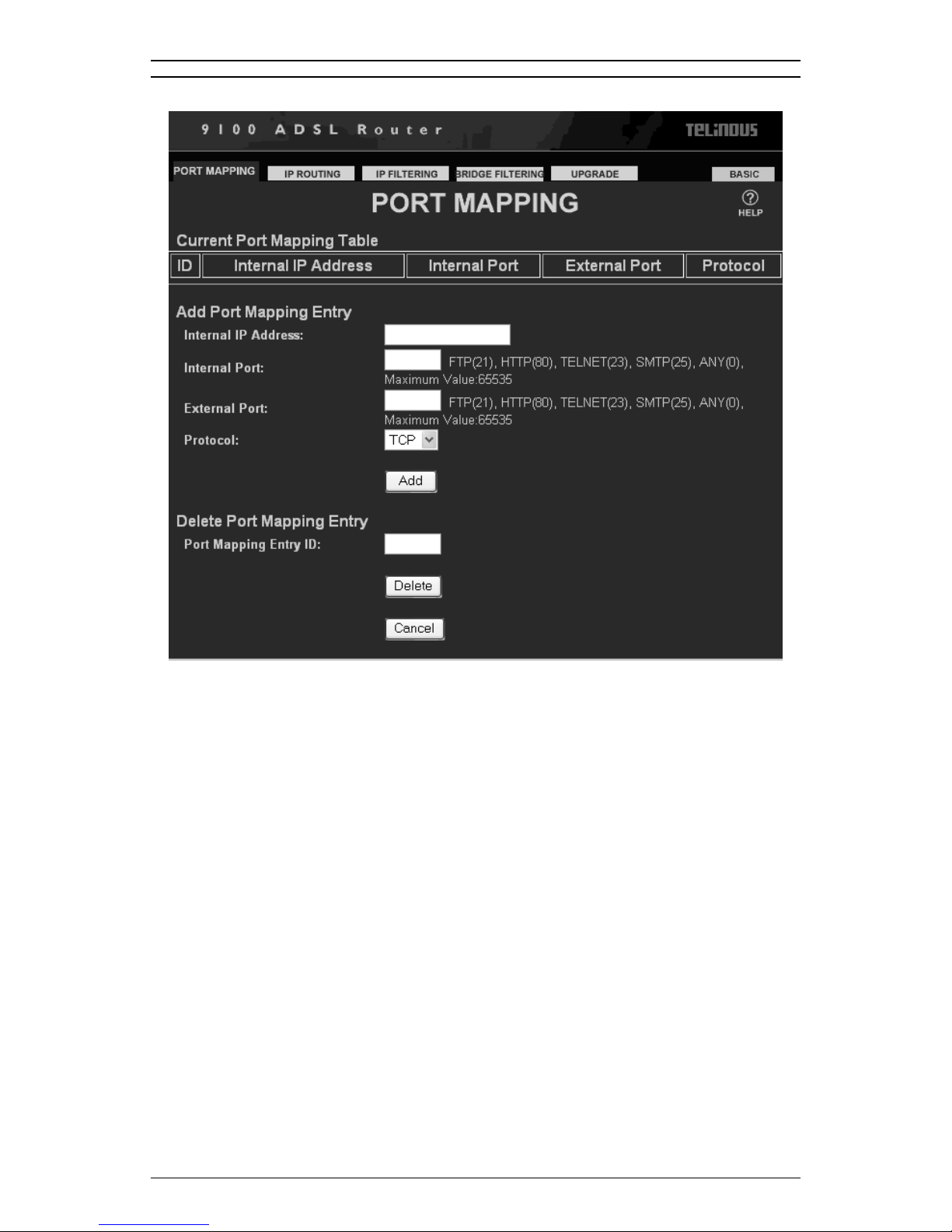
A. Click the PORT MAPPING tab on the top.
Port Mapping allows you to provide certain services (web hosting,
FTP server, or Telnet) or applications (PCAnywhere or Blizzard’s
StarCraft) to the Internet on your LAN. Incoming data packets with a
specific port (external port) can be mapped/routed to the specific
application or service (internal port) according to the Port Mapping
Table.
Current Port Mapping Table
The Current Port Mapping Table displays the ID (index number),
Internal IP Address, Internal Port #, Externa l Port #, and Protocol type
for each entry. When you click Add, a new Port Mapping Entry will be
created.
Add Port Mapping Entry
In the Add Port Mapping Entry section, you can enter values for each
of the following items:
36 User’s Guide
Page 37

Configuration
Internal IP Address: The IP Address for the PC running the
special service(s) within the ADSL
Router ’s private subne t. It is
recommended to assign a permanent
private IP Address (in the range of
192.168.1.2 - 192.168.1.254) to the PC
when the internal DHCP server is ON.
NOTE: Each time you assign a permanent IP Address to your network
PC, reboot your ADSL Router so the DHCP server can reserve it.
Internal Port: The port number of the PC running the
special service(s) within the ADSL
Router ’s subnet. A port is used to
distinguish between requests for
different services, such as 21 is for FTP,
80 is for HTTP, 23 is for Telnet and 25 is
for SMTP, etc.
External Port: The port numbe r associated with the
Dial-Out IP Address (please refer to
Internal Port for more details).
Protocol: The protocol type used depending on
the type of special service or application
you intend to provide. Currently, the
ADSL Router supports TCP and UDP
protocols.
Delete Port Mapping Entry
Port Mapping Entry ID: To delete an entry from the port mapping
table above, enter the associated ID
number and click Delete.
B. If you do not wish to send the configuration to your ADSL
Router, simply click Cancel.
An example on how to set up a WEB hosting service:
Internal IP Address: Enter 192.168.1.100 (Make sure the
WEB server’s IP Address is
192.168.1.100 and Subnet Mask is
255.255.255.0).
Internal Port: Enter 80.
External Port: Enter 80.
Protocol: Select TCP.
User’s Guide 37
Page 38
Configuration
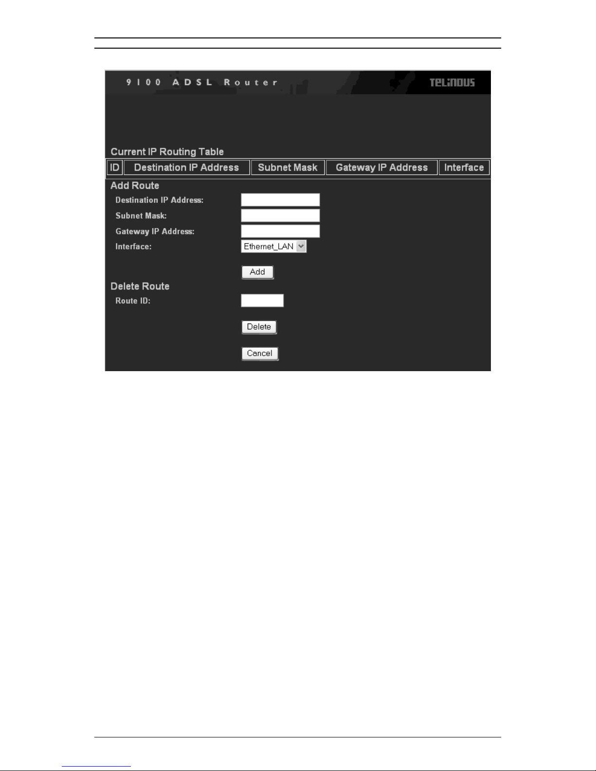
4.8 Advanced Configuration - IP ROUTING
A. Click the IP ROUTING tab on the top .
IP Routing designates the ADSL Router which pa th or route to use
when forwarding data packets. You will need to create an IP route
when there are other ADSL Routers on your LAN.
Current IP Routing Table
The Current IP Routing Table displays the index number (ID) ,
Destination IP Address, Subnet Mask, Gateway IP Address, and
Interface for each entry. When you click Add, a new IP Route is
created.
Add Route
In the Add Route section, you can enter values for each of the
following items:
Destination IP Address: The IP Address of where data packets
are to be sent.
Subnet Mask: The subnet mask of the Destination IP
Address.
38 User’s Guide
Page 39

Gateway IP Address: The IP Address of the router on the LAN
Interface: Determines wh et he r da ta packets are to
Delete Route
Route ID: To delete a route from the routing table,
B. If you do not wish to send the configuration to your ADSL
Router, simply click Cancel.
C. If you wish to update a pre-existing route, please delete the
original route and add a new route.
Configuration
where data packets are to be sent. The
Gateway IP Address can only be set if
the route uses the LAN interface .
be sent through the Ethernet_LAN,
Ethenet_WAN, or Modem.
enter the associated ID number and click
Delete.
User’s Guide 39
Page 40
Configuration
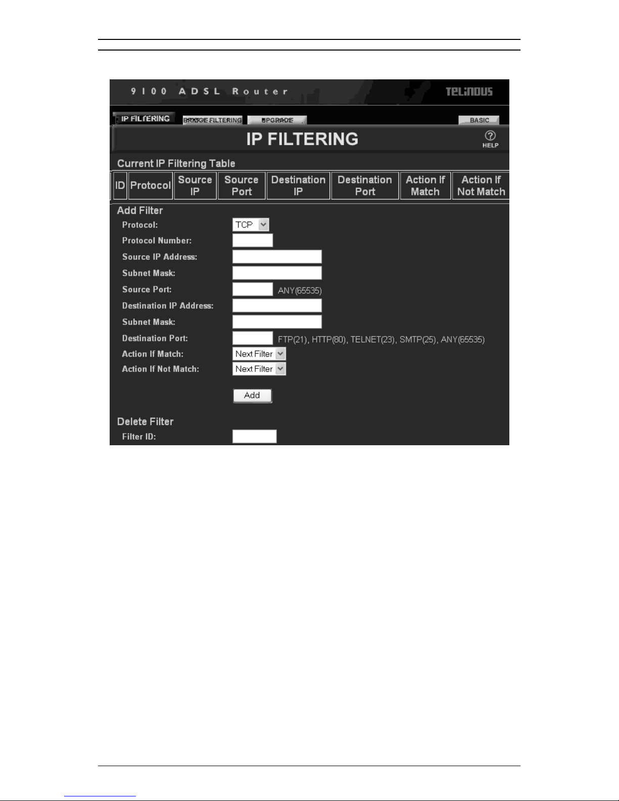
4.9 Advanced Configuration - IP FILTERING
A. Click the IP FILTERING tab on the top.
IP Filtering allows you to define up to 16 sequential filters, and each
filter can be set to examine, or filter, both source and destination data
packets.
Current IP Filtering Table
The Current IP Filtering Table displays the Filter ID, Protocol, Source/
Destination IP, Source/Destination Port # for ea ch filter, as well as the
action taken when the filter conditions are matched or not matched.
When you click Add, a new IP filter is created.
Add Filter
In the Add Filter section, you can enter valu es for each of the
following items:
40 User’s Guide
Page 41

Configuration
Protocol: Currently, Telindus 1120/1121 ADSL
Router supports TCP, UDP, ICMP, or
Other. If you select Ot her, then you need
to specify the following Protocol Number
field.
Protocol Number: The associated number for the desired
protocol. You need to enter a number if
you have selected Other in the previous
Protocol field.
Source IP Address: The IP Address of the device sending
the data packet.
Subnet Mask (Source): The subnet mask of the device sending
the data packet.
Source Port: The TCP/IP port of the service, such as
FTP, the web (HTTP), Telnet, or SMTP,
that sends the data packet.
Destination IP Address: The IP Address of the device receiving
the data packet.
Subnet Mask
(Destination): The subnet mask of the device receiving
the data packet.
Destination Port: The TCP/IP port of the service, such as
FTP, the web (HTTP), Telnet, or SMTP,
that receives the data pa cket.
The ADSL Router examines each entering data packet with the
above parameters to determine if they match (true) or do not match
(false).
For data packets that match or do not match the IP filtering
conditions, you can set an Action If Matched or Action If Not
Matched parameter to determine the data packet’s destination:
Pass: Automatically pass through the ADSL
Router.
Restrict: Pass if only there is an available
connection.
Discard: Packet is blocked and discarded.
Pass to next filter: Packet goes to the next filter in
Delete Filter
Filter ID: To delete an IP filter from the filtering
User’s Guide 41
sequence.
table, enter the associated ID number
Page 42

Configuration
B. If you do not wish to send the configuration to your ADSL
and click Delete.
Router, simply click Cancel.
42 User’s Guide
Page 43

4.10 Advanced Configuration BRIDGE FILTERING
Configuration
A. Click the BRIDGE FILTERING tab on the top.
Similar to the IP Filtering function in the previous section, Bridge
Filtering also allows you to define up to 16 sequential filters, and
each filter can be set to examine, or filter , bot h source and destination
data packets when the ADSL Router is in Snap/Bridge or Bridge
Routing mode.
Current Bridge Packet Filtering Table
The Current Bridge Packet Filtering Table displays the Filter ID,
Source/Destination MAC, as well as the action taken when the filter
conditions are matched or not matched. Whe n you click Add, a new
Bridge packet filter is created.
Add Filter
In the Add FiltedF Tf1.7( t)4Tw[()5.2(u click )]TJ/F7 1 TfateiGilter
User’s Guide 43
Page 44

Configuration
Destination MAC
Address: The MAC Address of the device
receiving data packages
The ADSL Router examines each entering data packet with the
above parameters to determine if they match (true) or do not match
(false).
For data packets that match or do not match the IP filtering
conditions, you can set an Action If Matched or Action If Not
Matched parameter to determine the data packet’s destination:
Pass: Automatically pass through the ADSL
Router.
Restrict: Pass if only there is an available
connection.
Discard: Packet is blocked and discarded.
Pass to next filter: Packet goes to the next filter in
sequence.
Delete Filter
Filter ID: To delete a bridge filter from the filtering
B. If you do not wish to send the configuration to your ADSL
table, enter the associated ID number
and click Delete.
Router, simply click Cancel.
44 User’s Guide
Page 45
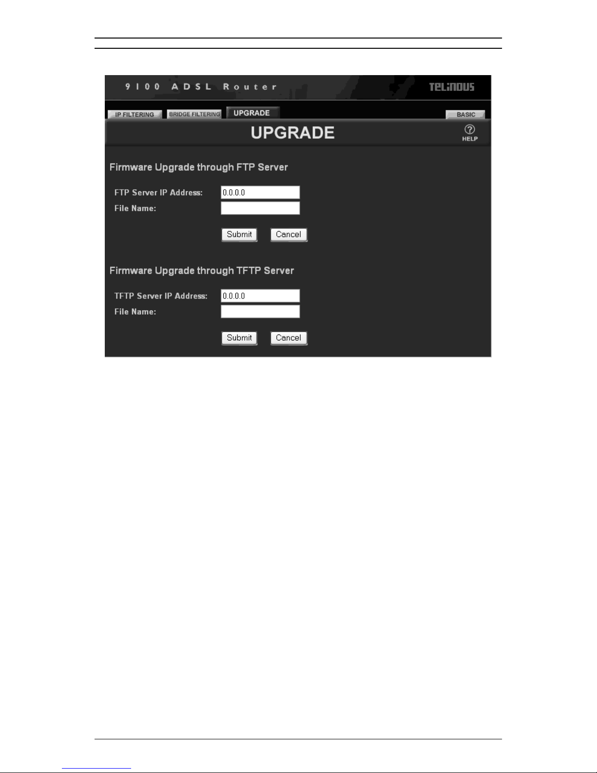
4.11 Advanced Configuration - UPGRADE
Configuration
A. Click the UPGRADE tab on the top.
The Upgrade feature allo ws you to upgrade your ADSL Router to the
latest firmware version. Firmwares can be downloaded to the ADSL
Router through either a FTP or TFTP server.
Please visit ARESCOM website at www.arescom.com for the FTP
Server IP Address and firmware File Name BEFORE you upgrade
the firmware.
B. Enter the following information if you want to download a
firmware to your ADSL Router:
FTP Server IP Address:The IP Address of the FTP or TFTP
server that contains the firmware.
File Name: The file name of the ADSL Router
firmware that you wish to download.
C. Click Upgrade to begin the firmware upgrade process. If you
do not wish to upgrade firmware, simply click Cancel.
User’s Guide 45
Page 46

Configuration
46 User’s Guide
Page 47

Troubleshooting 5
This Chapter Includes:
5.1 No SYNC/WAN Link LED Flashing...............47
5.2 Cannot Detect the NDS Unit ...........................48
5.3 DSL Service Seems Slow ................................48
This section is designed to answer some of the questions you might
have while operating the ADSL Router. Read each heading carefully
to find the solution to your problems.
5.1 No SYNC/WAN Link LED Flashing
• Make sure the phone cord from the wall is plugged into the
ADSL Router, then check to see if the ADSL Router has power
and is turned on.
• Be sure the phone jack you are using is working properly by
plugging a telephone into the phone jack and see if you can dia l
out.
5
55
• Make sure you have not accidentally plugged the RJ-11
telephone cable into the unit’s RJ-45 Ethernet port (the phone
cable will fit, but it is plugged into the wrong port).
• Verify that you are NOT using a microfilter on the ADSL line.
• Reboot your ADSL Router.
• You ma y rev iew an y ad dit ion a l docu m en tation.
If the above mentioned sugge stio ns still do no t solve you r pr ob le ms ,
your line may have been incorrectly provisioned. Contact your ISP’s
Technical Support to confirm that the line has been provisioned
correctly.
User’s Guide 47
Page 48

Page 49

Glossary
When you order Internet service, your provider will give you a great
deal of information. Definitions of common configur ation terms are
available below . Ple ase note that t erminology used by various remote
networks may vary.
ADSL (Asymmetric Digital Subscriber Line) - Currently the most
common DSL technology available that provides asymmetrical
bandwidth over a single copper wire p air (over your regular telephone
line). The downstream bandwidth from the network to the subscriber
is greater than the upstream bandwidth from the subscriber to the
network. ADSL speeds typically run from 1.5 Mbps to 8 Mbps
downstream and 64 Kbps to 640 Kbps upstream.
Bandwidth - The amount of data that can be transmitted by the
network “information highway”, used as an indication fo r speed of
data transmission. An Ethernet link is capable of moving 10 million
bits of data per second.
A
A
AA
Bit - The term used to refer to a single unit of data in digital data
communications. It takes 8 bits to make 1 byte, which is a unit of
measurement for computer data.
Bps (Bits per second) - Refers to the unit of measurement used for
data transmission speeds over a d at a co mmunicati on link, e. g. ADSL
runs at 6 Mbps (MegaBits per second).
Bridge - A hardware device that passes packets between multiple
network segments using the same networking protocol to connect the
different netwo rk segments. A DSL modem is a bridge that p asses
DSL from one network segment to another. Bridge operates at the
hardware layer and has no routing capabilities.
Broadband - Any high-bandwidth (see also Bandwidth) data
communication technology that runs at speeds of 200 Kbps or more
and allows combined transmission of voice, data, and video over a
single physical connection. Broadband is in contrast to narrowband
such as traditional 56K analog modem. DSL, Cable, wireless, and
satellite technology are all different types of broadband technology.
Byte - A unit of data equaling to 8 bits (1 Byte = 8 bits).
User’s Guide 49
Page 50

Glossary
DHCP (Dynamic Host Configuration Protocol) - An Internet
protocol that allows the DHCP server to dynamically assign IP
addresses to any client workstation (any device connecte d to your
LAN, such as a PC) for a set period of time an d then sends them back
so that they can be reassigned to other workstations. This feature
saves the ISP and Network Managers from having to manually
configure IP addresses for each PC on the LAN.
DSL (Digital Subscriber Line) - A new kind of digitized data
communication technology that delivers high-spe ed, two-way Internet
access over the traditional copper wire telephone line. DSL
technology allows the user to share their phone line with their DSL
line, providing an “always-on” Internet connectio n that runs at speed s
from 1 Mbps to 52 Mbps depending on the distance between the
customer site and the CO. There are many type o f DSLs called xDSL,
and the most commonly available DSL line is t he ADSL ( See ADSL),
which supports up to 6 - 8Mbps downstream. Other types of DSL
include SDSL, IDSL, HDSL, VDSL, RADSL, etc.
DSL technology can be accessed by connectin g a DSL modem at the
customer premise to the telephone line and computer. At the end of
the line, DSL-enabling equipment at the CO, such as a DSLAM,
aggregates or consolidates all the custo mer DSL lines an d routes the
data traffic onto a backbone network for distribution to the ISP or
corporate networks.
DNS (Domain Name System) - A mechanism that translates host
domain names into its numeric IP Address and vice-versa. A domain
name is an easy-to-remember nickname for numerical IP addresses
required by a computer, such as [email protected].
Encapsulation - The encapsulating or enclosing data within a
particular IP header. Sometimes the entire frame from one netwo rk is
placed in the header used by the data link layer protocol of another
network.
Encryption - A specific algorithm used to encr ypt or en code the da t a
so that it becomes unreadable to unauthor ized users that do not know
the decryption key. A good example of encryption technology is WEP
(Wired Equivalent Private).
Ethernet - Most popular LAN (Local Area Network) technology that
uses CSMA/CD (Collision Detection) and transfers data between
workstations over a variety of cable types at 10Mbps, also called
10BaseT. Most Ethernet LANs use twisted pair 10BaseT cables and
support both Ethernet as well as Fast Ethernet at 100Mbps
(100BaseT).
50 User’s Guide
Page 51

Glossary
Firewall - A security device (either hardware, software, or a
combination of both) that selectively blocks out or filters unwanted IP
traffic from a public network. Firewall allows the private LAN network
to be invisible to the public network outsid e, preventing intrusion from
unauthorized users.
Hub - A hardware device that repeats all data traffic to all CPE
(Customer Premises Equipment) ports. A hub functions as the cent er
of a LAN and all other network devices on the LAN, including PCs,
printers, DSL modem or Gateways, are connected to the hub through
cabling.
Internet - A massive worldwide network of computer networks
interconnecting thousands of computers and networks around the
world and readily accessible from any computer with a modem or
router connection and the corresponding software.
IP (Internet Protocol) - A protocol sta ndard for the Int ernet. A kind of
Internet software that ke eps track of all the addresses on the In te rn et
for different nodes, forwards outgoing IP traffic, and recognizes
incoming IP traffic.
IP Address - numeric address assigned to each machine on the
Internet. Consists of four sets of one, two, or three octal digits
separated by periods.
ISP (Internet Service Provider) - The telecommunication company
that provides Internet service for the subscriber. The ISP can be a
telephone company, a CLEC or ILEC, or any other com pany that
provides Internet access to th e en d us er such as A OL , Ear th lin k or
MSN.
LAN (Local Area Network) - A collection of privately owned,
interconnected computers within a confined service area.
PPPoE (Point to Point Protocol over Ethernet) - It is a protocol that
allows a computer to access the Internet using a dial-up phone line
and a high-speed modem or router. Relying on two widely accepted
standards, Ethernet and point to point protocol (PPP), it makes high
speed access easier to use for end consumers, and more seamless
to integrate into the existing infrastructure for carriers and ISPs.
Virtual Path Identifier - A virtual path is a semi-permane nt
connection between endpo i nts in an ATM network and may support
one or more virtual channels. In Private Vi rtual Circuit (PVC) mode,
the Virtual Path (VP), which is a header subfield, is assigned
manually when the ADSL Router is used. Different VP values allow
the endpoints to discriminate between different virtual connections
and ATM nodes.
User’s Guide 51
Page 52

Glossary
Virtual Channel Identifier - Each connection in an ATM network is
characterized by a Virtual Channel (VC). This is a header subfield
that is assigned manually when the ADSL Router is used. A VC has
only local significance on the link between ATM nodes. When the
connection is released, the VC value on the involved links will be
released and can be reused by other connections.
52 User’s Guide
Page 53

Reference
B
B
BB
B.1 FCC Statement
This equipment has been tested and found to comply with the limits
for a class B digital device, pursuant to Part 15 of the FCC rules.
These limits are designed to provide reasonable protection against
harmful interference in a residential installation. This equipment
generates, uses and can radiate radio frequency energy and, if not
installed and used in accordan ce with the instructions, may cause
harmful interference to radio communications. However, there is no
guarantee that interference will not occur in a particular installation. If
this equipment does cause harmful interference t o radio or television
reception, which can be determined by turning the equipme nt off and
on, the user is encouraged to try to correct the interference by one or
more of the following measures:
• Reorient or relocate the rece ivin g an te nn a .
• Increase the separation between the equipment and receiver.
• Connect the equipment into an outlet on a circuit different from
that to which the receiver is connected.
• Consult the dealer or an experienced radio/TV technician for
help.
Use only shielded cables to connect I/O devices to this equipment.
You are cautioned that changes or modifications not expressly
approved by the party responsible for compliance could void your
authority to operate the equipment.
This device complies with part 15 of the FCC rules. Operation is
subject to the following two conditions. (1) This device may not cause
harmful interference and (2) this device must accept any int erfer ence
received, including interference that may cause undesired operation.
User’s Guide 53
Page 54

Reference
B.2 FCC Part 68 Requirements
This equipment complies with Part 68 of the FCC Rules. On the
bottom of this equipment is a label that contains, among other
information, the FCC Registration Number and Ringer Equivalence
Number [REN] for this equipment. If requested, this information must
be given to the telephone company.
The REN is used to determine the maximum number of devices
connected to your telephone line that will ring in response to an
incoming call. In most but not all areas, the total REN of devices
connected to a line should not exceed five [5.0]. To find out the total
permitted in your area, contact your local telephone company.
If your telephone equipment cause harm to the telephone network,
the telephone company may discontinue your service temporarily. If
possible, they will notify you in advance. But if advance notice is not
practical, you will be notified as soon as possible. You will be
informed of your right to file a complaint with the FCC.
Your telephone company may make changes in its facilities,
equipment, operations or procedures that could affect the proper
functioning of your equipment. If they do, you will be notified in
advance to give you and opportunity to maint ain uninterrupted
telephone service.
If you experience trouble with this product, please contact Telindus,
Inc. for information on obtaining service or repairs. The telephone
company may ask that you disconnect this equipment from the
network until the problem has been corr ected or until you are sure
that the equipment is not malfunctioning.
This equipment may not be used on coin service provided by the
telephone company. Connection to party lines is subject to state
tariffs.
54 User’s Guide
 Loading...