

Telindus 1110ADSL Bridge, 1111 ADSL Bridge User Manual

USER’S GUIDE
Telindus Technical Publications - Geldenaaksebaan 335 - B-3001 Leuven Belgium - Tel. +32 16 382011
1110/1111 ADSL Bridge
User’s Guide
December 2002
WARNING!!!
Please carefully follow this User’s Guide to
complete the USB driver installation.

ii User’s Guide
Version 6.2
©TELiNDUS

iii User’s Guide
Copyright and Statements Telindus 1110/1111 ADSL Bridge
Copyright Notice
The information and descriptions contained in this publication are the property of Telindus. Such
information and descriptions must not be copied or reproduced by any means, or disseminated or
distributed without the express prior written permission of Telindus.
Disclaimer
This publication could include technical inaccuracies or typographical errors, for which Telindus
never can or shall be held liable. Changes are made periodically to the information herein; these
changes will be incorporated in new editions of this publication. Telindus may make improvements
and/or changes in the product(s) described in this publication at any time, without prior notice.
Safety Warnings
Always observe standard safety precautions during installation, operation and maintenance of this
product. Only qualified and authorized service personnel should carry out adjustment, maintenance
or repairs to this instrument. Either the operator or the user should perform no adjustment,
maintenance or repairs.
The interfaces on the Telindus 1110/1 1 11 ADSL BRIDGE should only be connected to circuit types
as listed below:
Carefully read the safety instructions in the “Hardware Installation” section.
Your Feedback
Your satisfaction about this purchase is an extremely important priority to all of us at Telindus.
Accordingly, all electronic, functional and cosmetic aspects of this new unit have been carefully
and thoroughly tested and inspected. If any fault is found with this unit or should you have any
other quality-related comment concerning this delivery, please submit the Quality Comment Form
on our web page http://www.telindus.com/accessproducts.
Interface Connector Circuit
Line Interface RJ-11 TNV-1
LAN Interface RJ-45 SELV
USB Interface Type-A USB Connector SELV
Version 6.2 ©TELiNDUS

Telindus 1110/1111 ADSL Bridge Copyright and Statements
User’s Guide iv
Conformity Statements
http://www.telindus.com/products/conformity/ -> Products -> Choose a
product -> Download certificates
Hereby, TELINDUS declares that this Telindus 1110/1111 ADSL BRIDGE is in
compliance with the essential requirements and other relevant provisions of Directive
1999/5/EC.
Bij deze, verklaart TELINDUS dat deze Telindus 1110/1111 ADSL BRIDGE in
overeenstemming is met de essentiële vereisten en andere relevante bepalingen van
Richtlijn 1999/5/EC.
Par la pr é s ente, TE L I N DUS déc l a r e que ce Telind u s 1110/1111 A D S L BRIDGE e s t en
conformité avec les exigences essentielles et autres articles applicables de la Directive
1999/5/EC.
Hiermit, TELINDUS erklärt daß dieser Telindus 1110/1111 ADSL BRIDGE ist in
Fügsamkeit mit den wesentlichen Anforderungen und anderen relevanten
Bereitstellungen von Direktive 1999/5/EC.
Mediante la presente, TELINDUS declara que el Telindus 1110/1111 ADSL BRIDGE
cumple con los requisitos esenciales y las demás prescripciones relevantes de la
Directiva 1999/5/CE.
A TELINDUS declara que o Telindus 1110/1111 ADSL BRIDGE cumpre os principais
requisitos e outras disposições da Directiva 1999/5/EC.
Col presente, TELINDUS dichiara che questo Telindus 1110/1111 ADSL BRIDGE è in
acquiescenza coi requisiti essenziali e stipulazioni attinenti ed altre di Direttivo 1999/5/
EC.
Με το παρόν, η TELINDUS δηλώνει ότι αυτό το TELINDUS 1110/1111 ADSL BRIDGE είναι
συµµορφούµενο µε τις βασικές απαιτήσεις και µε τις υπόλοιπες σχετικές διατάξεις της οδηγία
ς
1999/5/EC.
v User’s Guide
Copyright and Statements Telindus 1110/1111 ADSL Bridge
Safety Instructions
IMPORTANT SAFETY INSTRUCTIONS
Unplug the unit from the wall power outlet before installing, adjusting or servicing.
ACHTUNG! WICHTIGE SICHERHEITSINSTRUKTIONEN
Vor sämtlichen Arbeiten am Gerät (Installation, Einstellungen, Reparaturen etc.) sollten Sie den
Netzstecker aus der Steckdose ziehen.
SAFETY WARNING
To avoid damage to the equipment, please observe all procedures described in this chapter.
SICHERHEITSBESTIMMUNGEN
Um eine Beschädigung des Gerätes zu verhindern, beachten Sie bitte unbedingt die
Sicherheitsbestimmungen, die in diesem Abschnitt beschrieben werden.
Ensure that the unit and its connected equipment all use the same AC power and ground, to reduce
noise interference and possible safety hazards caused by differences in ground or earth potentials.

Telindus 1110/1111 ADSL Bridge Copyright and Statements
User’s Guide vi
Unpacking
Rough handling during shipping causes most early failures. Before installation, check t he shipping
carton for signs of damage:
• If the carton box is damaged, please place a claim with the carrier company
immediately.
• If the carton box is undamaged, do not dispose of it in case you need to store the unit
or ship it in the future.
Selecting a Site
WARNING
Always place the unit on its feet without blocking the air vents.
Do not stack multiple units directly onto each other, as stacking can cause heat build-up that could
damage the equipment.
ACHTUNG
Stellen Sie das Gerät niemals seitli ch, sonder n nur auf den Füßen auf und achten Sie darauf, daß die
Lüftungsschlitze an der Seitenverkleidung frei bleiben.
Stapeln Sie nicht mehrere Geräte direkt übereinander, dies kann zu einem Hitzestau führen.

User’s Guide December 2002 vii
Table of Contents
CHAPTER 1 PRODUCT INTRODUCTION . . . . . . . . . . . . . . . . . . 1
1.1 Overview .............................................................................................................................1
1.2 Package Includes .................................................................................................................1
1.3 Minimum System Requirements .........................................................................................1
1.4 Web-based Management Interface ......................................................................................2
1.5 Information You Will Need ........................................................................... .....................2
1.5.1 Utilizing the Ethernet Interface ...................... ....................................................................................2
1.5.2 Utilizing the DSL Interface ................................................................................................................. 2
CHAPTER 2 HARDWARE INSTALLATION . . . . . . . . . . . . . . . . 3
2.1 Front Panel Description ........................... .... ..................................................................... ..3
2.2 Back Panel Description .......................................................................................................4
2.3 Before You Begin ...............................................................................................................4
2.3.1 Personal Safety ................................................................................................................................... 4
2.3.2 Product Handling ...............................................................................................................................4
2.3.3 Location & Placement ........................................................................................................................ 4
2.4 Setup Instructions ................................................................................................................5
2.4.1 Connecting the Ethernet Cable .......................................................................................................... 5
2.4.2 Connecting the USB Cable ................................................................................................................. 6
2.4.3 Connecting the DSL Cable ................................................................................................................. 7
2.4.4 Connecting the Power Adapter .......................................................................................................... 7
CHAPTER 3 NETWORK CONFIGURATION . . . . . . . . . . . . . . . . 9
3.1 USB Driver Installation ......................................................................................................9
3.1.1 Installing USB Drivers on Windows 98SE/ME ..................................................................................9
3.1.2 Installing Software Drivers on Windows 2000/XP ...........................................................................11
3.2 TCP/IP Installation ............................................................................................................13
3.2.1 Detecting TCP/IP in Windows 95/98SE/Me .....................................................................................13
3.2.2 Installing TCP/IP in Windows 95/98SE/Me ..................................................................................... 13
3.2.3 Configuring TCP/IP in Windows 95/98SE/Me ................................................................................. 14
3.2.4 Detecting TCP/IP in Windows NT .................................................................................................... 15
3.2.5 Installing TCP/IP in Windows NT .................................................................................................... 15
3.2.6 Configuring TCP/IP in Windows NT ................................................................................................16
3.2.7 Configuring TCP/IP in Windows 2000 .............................................................................................16
3.2.8 Configuring TCP/IP in Windows XP ................................................................................................18

viii December 2002 User’s Guide
CHAPTER 4 SOFTWARE CONFIGURATION . . . . . . . . . . . . . 19
4.1 Configuration Using Web Browser ..................................................................................19
4.2 Basic - SETUP .................................................................................................................20
4.2.1 System ...............................................................................................................................................20
4.2.2 PPP Bridge Setting .................................................................................................... .......................20
4.2.3 DNS .......................... ............................. ............................... ................................ .............................21
4.2.4 SNMP ..................... .......................................... ........................................... ......................................21
4.3 Basic - PPP CONNECTION ............................................................................................ 21
4.4 Basic - PPP PROFILES ................................................................ .... ..... .......................... 22
4.5 Basic - PVCs ................................................................................................... ................. 23
4.6 Basic - LAN .............................................. .... ..... ..............................................................24
4.6.1 IP Setting ........................................................................ .......................... .........................................24
4.7 Basic - STATUS ........................................................................... ...................................25
4.7.1 System ...............................................................................................................................................25
4.7.2 DSL ...................................................................................................................................................25
4.7.3 Ethernet LAN ....................................................................................................................................26
4.8 Basic - DIAGNOSTIC ........................................................................... .......................... 27
4.9 Advanced - BRIDGE FILTERING .................................................................................. 28
4.9.1 Current Bridge Packet Filtering Table .................................................... .........................................28
4.9.2 Add Filter .......................................... ..................................................... ...........................................28
4.9.3 Delete Filter ......................................................................................................................................29
4.10 Advanced - UPGRADE ................................................................................................... 30
4.10.1 Firmware Upgrade through FTP Server ..........................................................................................30
4.10.2 Firmware Upgrade through TFTP Server ........................................................................................30
CHAPTER 5 TROUBLESHOOTING . . . . . . . . . . . . . . . . . . . . . . 31
5.1 No Sync/WAN Link LED Flashing ................................................................................. 31
5.2 Cannot Detect the ADSL Bridge ...................................................................................... 31
5.3 DSL Service Seems Slow ......................................................... ..... ................................... 31
APPENDIX A GLOSSARY . . . . . . . . . . . . . . . . . . . . . . . . . . . . . . . . 33
APPENDIX B REFERENCE . . . . . . . . . . . . . . . . . . . . . . . . . . . . . . . 37
B.1 FCC Statement ................................................................................................................. 37
B.2 FCC Part 68 Requirements ....................................................... ..... .... ............................... 38

User’s Guide December, 2002 1
CHAPTER 1: PRODUCT INTRODUCTION
1.1 Overview
The Telindus 1110/1111 ADSL Bridge is the ultimate networking solution for any
office or home searching for ultra-fast access to the Internet and remote networks over
ADSL. Telindus 1110/1111 ADSL Bridge is a stand-alone device with true plug-andplay capability. It works with any computer using an Ethernet port or USB port.
The purpose of this manual is to help you ease through the installation process by providing simple step-by-step instructions in setting up your ADSL Bridge. Please read
this guide carefully before you start installing the device.
1.2 Package Includes
• Telindus 1110 /1111 ADSL Bridge
• AC to AC power adapter (x 1)
• Telindus CD-ROM (x 1) includes:
- User’s Guide in PDF format
- USB Driver
• RJ-11 to RJ-11 ADSL phone cable (x 1)
• RJ-45 to RJ-45 straight-through Ethernet cable (x 1)
• Detachable USB cable (x 1)
• Quick Setup Guide (x 1)
1.3 Minimum System Requirements
• ADSL line
• Microsoft Windows 98 or later version
• 166 MHz Pentium or equivalent processor
• 16 MB RAM or more
• 170 MB available free hard disk space before installation
• Available 10BaseT Ethernet port or USB port on the main computer
• CD-ROM Drive
NOTE: DO NOT connect the USB cable to the ADSL bridge until AFTER you install the
USB driver and are instructed to complete the connection in the software installation
process.
NOTE: It is important to install the latest Windows Service Pack whenever you add compo-
nents to your system because older system files may be copied back to Windows during installation. Reboot your PC after installation.

Web-based Management Interface
2 December, 2002 User’s Guide
1.4 Web-based Management Interface
Through the built-in web-based GUI (Graphic User Interface), you can change Telindus 1110/1111’s
settings, upgrade its firmware and monitor other wireless clients on the network. To use this management system, please follow the steps below:
Step 1. Open your browser.
Step 2. Enter the ADSL Bridge's IP address (default: 192.168.1.1) in the browser Location field (Netscape Nav-
igator) or Address field (Internet Explore).
Step 3. Press Enter to connect.
1.5 Information You Will Need
T o configure your router, you will need to receive information from your ISP and the remote network to
which you connect, such as an Internet Service Provider (ISP) or a company server. Consult the sections
below for a detailed list of information on utilizing the Ethernet interface and DSL interface. If you are
unfamiliar with any of the terms listed, refer to “GLOSSARY” on page 33.
1.5.1 Utilizing the Ethernet Interface
The following information should be obtained from your ISP:
• IP address
• Subnet mask
• Gateway IP address
1.5.2 Utilizing the DSL Interface
The following information related to your DSL connect ion which should be obtained from your ISP:
•VPI
•VCI
• PPP User name & Password (Only if encapsulation mode is in PPP)
• Encapsulation type
• DNS address

User’s Guide December, 2002 3
CHAPTER 2: HARDWARE INSTALLA TION
This chapter describes the front/back panel layout and installation procedure for the Telindus
1110/1111 ADSL bridge.
2.1 Front Panel Description
Figure 2.1 Telindus 1110 ADSL Bridge Front Panel
Figure 2.2 Telindus 1111 ADSL Bridge Front Panel
TABLE 1:Telindus 1110/1111 ADSL Bridge LED Description
LED COLOR STATUS DESCRIPTION
PWR
(Power)
Green
On Power is supplied to the ADSL bridge.
Off Power is not supplied to the ADSL bridge.
DIAG
(Diagnostic)
Yellow
On
There may be a software malfunction or a problem with
the ADSL bridge.
Flashing The ADSL bridge is in self-diagnostic mode.
Off The ADSL bridge has successfully booted up.
LAN Green
On
Indicates a valid Ethernet link is established between the
ADSL bridge and the Ethernet network.
Flashing Indicates data is flowing from/to this port.
Off No Ethernet link.
USB Yellow
On
Indicates a valid USB link is established between the
ADSL bridge and the Ethernet network.
Flashing Indicates data is flowing from/to this port.
Off No USB link.
WAN LINK Green
On
Indicates a valid DSL connection between the remote
DSL network and the ADSL bridge.
Off No WAN link.
WAN ACT
(Activity)
Yellow
Flashing Indicates data is flowing from/to this port.
Off No WAN data activity.
Back Panel Description
4 December, 2002 User’s Guide
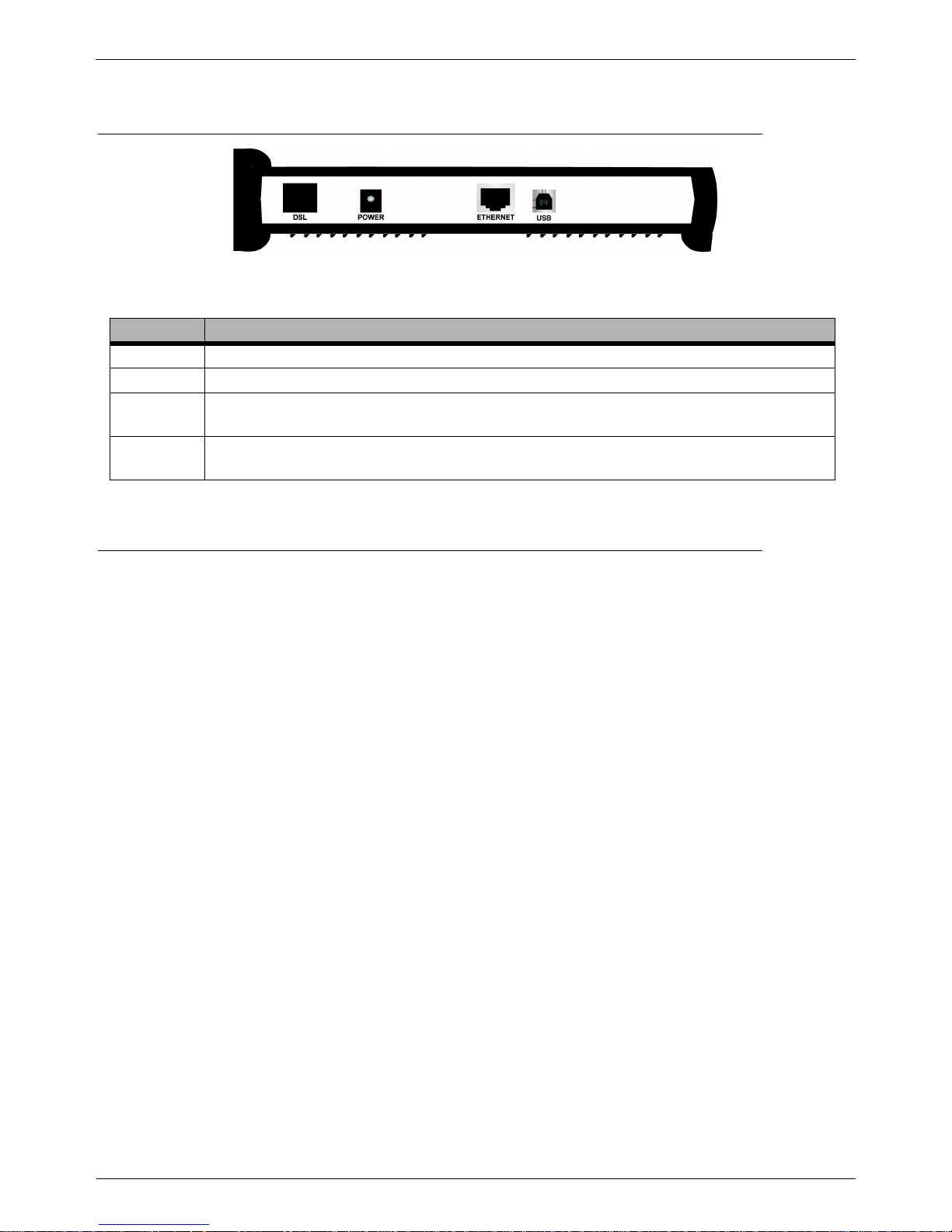
2.2 Back Panel Description
Figure 2.3 Telindus 1110 ADSL Bridge Back Panel
2.3 Before You Begin
CAUTION!!! Turn off all electronic devices, including your personal computer, before you begin to connect and
disconnect cables.
2.3.1 Personal Safety
• In case of emergency, locate the closest electricity power-off switch.
• Refrain from touching any active wires or terminals.
• Remove any jewelry before working on equipment connected to electricity.
• Keep cables away from walkways.
• Dispose this product in accordance with national laws and regulations.
2.3.2 Product Handling
• Keep ventilation slots clear.
• Operate in a clean and dust-free location.
• Cables must be attached to the correct interfaces; to do otherwise may result in damaging the ADSL
bridge or produce hazardous voltage.
• Do not operate or store the product in an environment that surpasses temperature or humidity specifications.
2.3.3 Location & Placement
• Choose a location for the ADSL bridge that is close to a power outlet and a nearby telephone outlet. In
addition, select a convenient location that does not experience too much foot traffic and is away from
sunlight.
• The optimum spot to place the ADSL bridge is on a level surface – such as a desktop, shelf, or table.
• Place the ADSL bridge on the predetermined surface, so you can see the back panel for accessible cable
connection.
TABLE 2:Telindus 1110/1111 ADSL Bridge Back Panel Interface Description
PORT DESCRIPTION
DSL
The DSL port connects the ADSL bridge to the telephone outlet with DSL service.
POWER
The POWER port is where you connect the AC power adapter to the ADSL bridge.
ETHERNET
The ETHERNET port is where you connect the ADSL bridge to a PC, hub or switch on your
wired LAN network.
USB
The USB interface allows you to connect your ADSL Bridge to your PC using an USB detachable
cable.
User’s Guide December, 2002 5
Setup Instructions
2.4 Setup Instructions
Before you start the setup process, make sure once again that you:
• Shut down and disconnect your DSL broadband connection properly.
• Turn off all Telindus equipment.
2.4.1 Connecting the Ethernet Cable
Step 1. Locate your Ethernet cable (included).
Step 2. Attach the Ethernet cable to the ETHERNET port of your ADSL bridge.
Step 3. Plug in the loose end of the Ethernet cable to your Ethernet network. Y ou have 3 options to connect to the Ether-
net depending on your network environment:
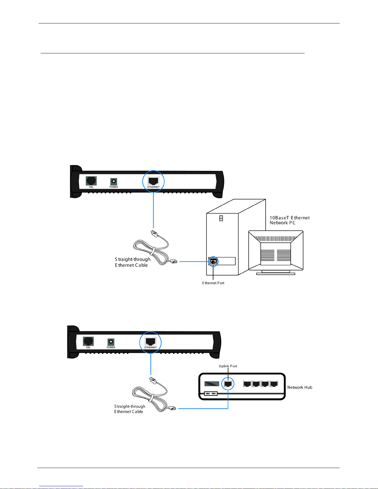
OPTION 1.Connecting to a single PC: Attach the included straight-through Ethernet cable to the Ethernet
port on a PC.
Figure 2.4 Connecting the ADSL Bridge to PC’s Ethernet Interface
OPTION 2.Connecting to a network hub with uplink port available: Attach the included straight-through
Ethernet cable to the uplink port on a hub.
Figure 2.5 Connecting the ADSL Bridge to the Uplink Port of a Network Hub
Setup Instructions
6 December, 2002 User’s Guide
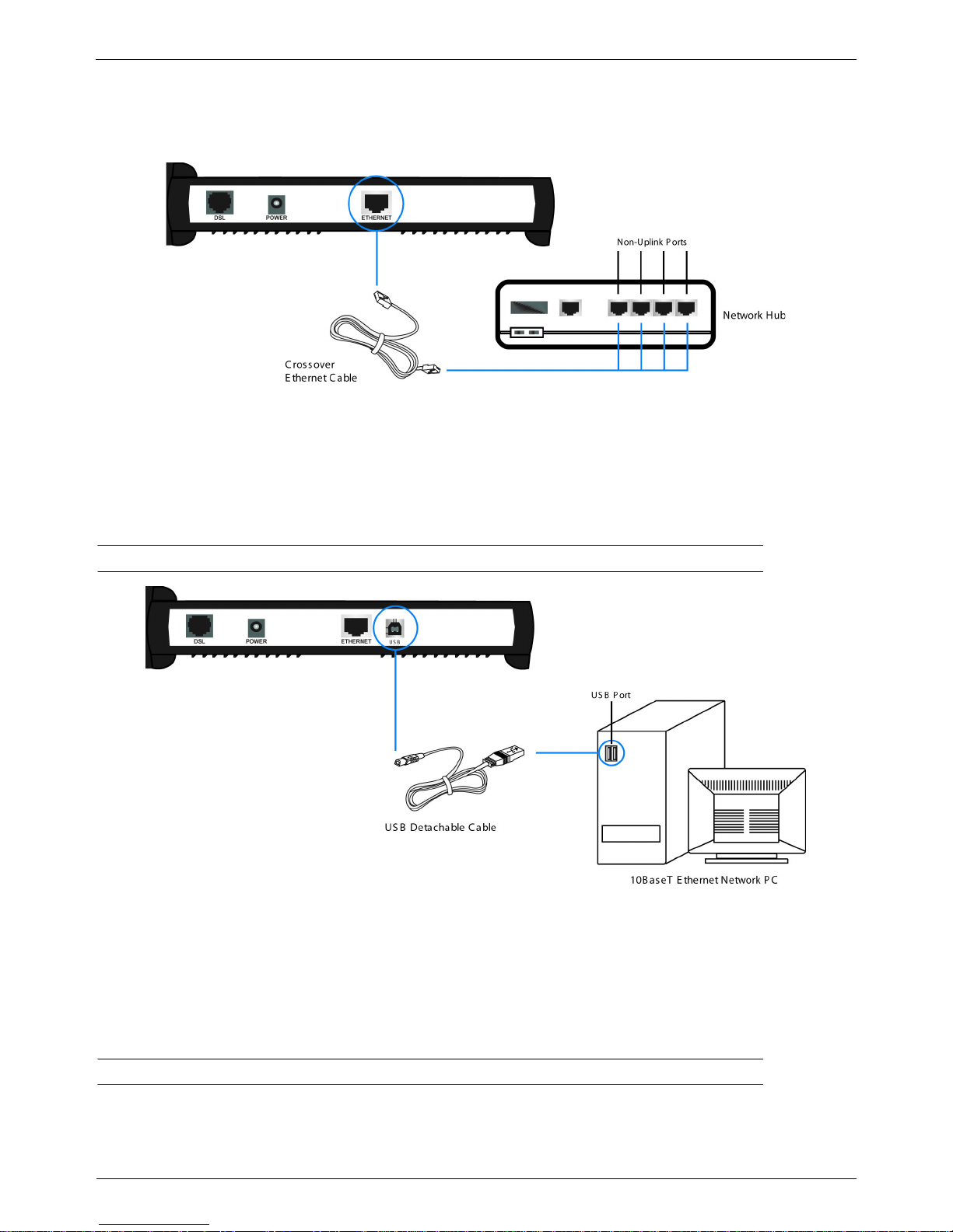
OPTION 3.Connecting to a network hub with non-uplink port available: If the uplink port is unavailable,
then you can use a crossover Ethernet cable (not included) and attach it to the non-uplink port(s) on
a network hub.
Figure 2.6 Connecting the ADSL Bridge to the Non-Uplink Ports of a Network Hub
Step 4. Once the ADSL bridge is powered on, the LAN LED on the front panel should be on to indicate a valid Ethernet
connection. If the LED is not lit, repeat steps 1 through 3 above.
2.4.2 Connecting the USB Cable
NOTE: DO NOT plug the USB cable to the ADSL bridge until AFTER you have installed the USB driver.
Figure 2.7 Connecting the ADSL Bridge to the PC’s USB Interface
Step 1. Plug the Type-B (square-shaped) end of the USB detachable cable (included) into the USB port of the NDS unit.
Step 2. Plug the Type-A (flat-shaped) end of the USB detachable cable into the USB port of your PC.
Step 3. The USB LED on the front panel should be on to indicate a valid USB connection. If the USB LED is not lit,
repeat steps 1 and 2 above.
NOTE: See “USB Driver Installation” on page 9 for more information.
 Loading...