

Telikou MS-500 Instruction Manual

TELIKOU Intercom System
MS-500(4+1 channel) Main Station
Instruction Manual
© TELIKOU Systems
All Rights Reserved

TELIKOU
MS-500(4+1Channel)Main Station
1
Contents
I. General
II. Specialty
III. Basic operation
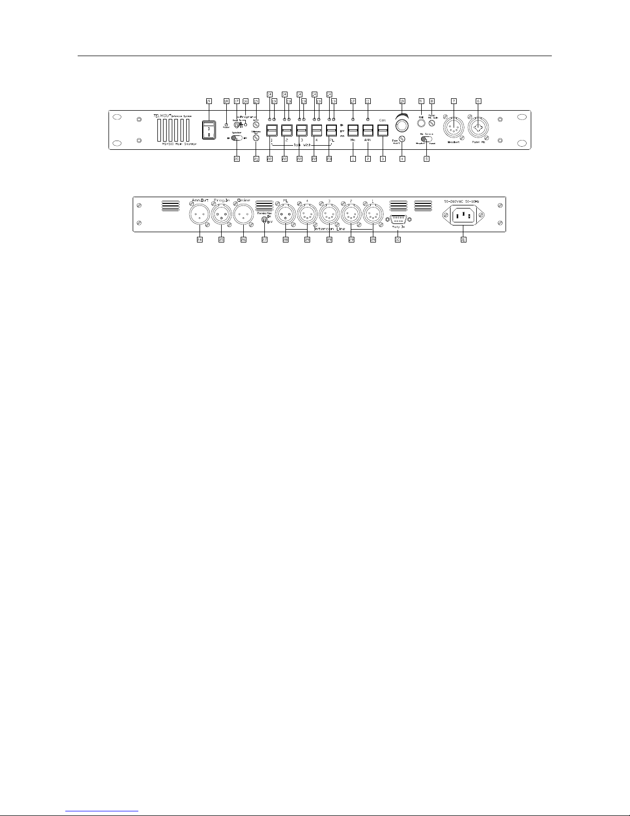
1. Front panel
1) Microphone switch (Mic.)
2) Announce switch (ANN.)
3) Call switch (Call)
4) Tone Alert volume control (Tone Alert)
5) Microphone Selection switch (Mic. Select)
6) Panel Microphone plug (Panel)
7) Headset plug (Headset)
8) Panel Microphone Gain control (Panel Mic. Gain)
9) Remote Microphone switch (RMK)
10) Listen Volume control (Volume)
11) Announce LED (ANN. LED)
12) Microphone LED (Mic. LED)
13) Talk LED (Talk LED)
14) Call LED (Call LED)
15) Program Level control (Program Level)
16) Program Feed To LED (Feed To LED)
17) Program Feed To switch (Program Feed To)
18) Power LED (Power LED)
19) Power Switch (Power)
20) Speaker (Speaker)
21) Sidetone Null control (Sidetone Null)
A).Sidetone Null control on gooseneck microphone and panel speaker
B).Sidetone Null control on headset
C).Sidetone Null control on system
22) Talk With switch (Talk With)
23) Party-Line talk switch (PL)
2. Rear Panel
24) Announce output connector (ANN. Out)
25) Program Input connector (Prog. In)
26) Online connector (Online)
27) Termination switch (Termination)

TELIKOU
MS-500(4+1Channel)Main Station
2
28) Party-Line channel cable connector (Intercom Line)
29) Tally channel cable connector
30) Tally light external control signal receiver connector (Tally In)
31) Power connector
IV. Cable
1. Cable selection
2. Cable connect
V. Troubleshooting: Q&A
VI. Technical Specification
I. General
Thank you for choosing TELIKOU intercom product. MS-500 main station can be used for television
station, communication center, UB truck, live performance and any other environment need
communication. Work with BK-500 belt pack, it can start Tally light function on four channels.
This system adopts wired connection, and has following features, free of external emission
interference, stable and reliable performance, flexible configuration, full-duplex communication,
clear and loud communication sound, easy operation, and strong noise resistance.
II. Specialty
Four 2-wire channel with tally, one 2-wire channel without tally.
All the operations finished on panel easily.
Automatic cut program input when talking on the channel.
Automatic Microphone identifies circuit.
Remote microphone kill(RMK)。
XLR/6.35mm compatible panel microphone plug.
Automatic circuit short protection and indication.
III. Basic Operation
TELIKOU
MS-500(4+1Channel)Main Station
3
1. Front Panel
1) Microphone switch (Mic.)
Turn up or down microphone switch handle will send amplified microphone signal through intercom
line. When this function is active, the LED above will light. The switch positions are as follow:
ON: The selected microphone is activated, the switch is self-locked.
OFF: The selected microphone is off.
PTT: The selected microphone is activated, release and reset.
Note:
When panel speaker and microphone switch are both activated, the signal was sent to speaker will
be deduct 6dB to reduce the feedback. Please turn off microphone after use.
2) Announce switch (ANN.)
Send selected microphone signal to ANN. Out connector which is at rear panel. When this function
is active, the LED above will light. The switch positions are as follow:
ON: Send signal from selected microphone to ANN. OUT, the switch is self-locked.
OFF: break the connection between selected microphone and ANN.OUT rear back.
PTT: Send signal from selected microphone to ANN. OUT, release and reset
3) Call Switch (Call)
Before use call function, please turn on the channel which want to talk. Turn up or down the call
switch handle will sent a call signal to all the connected channels. The call LED above lights red.
This switch is without self-locking function, release and reset.

TELIKOU
MS-500(4+1Channel)Main Station
4
4) Tone Alert Volume Control
When MS-500 receives external call signal, the internal buzzer will sent a hum to panel speaker and
earphone. This knob adjusts the hum level.
5) Mic. Select Switch
Set the Mic. select switch to select whether the panel microphone or the headset microphone is
active.
6) Panel Mic. Connector
This is a dual-purpose connector, supports XLR and 1/4inch plug.
The wiring of 3-pin XLR microphone is as follow:
Pin 1 – Mic. common
Pin 2 – Mic. hot
Pin 3 – Null
7) Headset connector
4-pin XLR Male or 5-pin XLR Female
EARPHONE: Dynamic 50-2000 ohm
MICROPHONE: Dynamic 100-600 ohm
The wiring of headset is as follow:
Pin 1—Mic. common
Pin 2—Mic. hot
Pin 3--headphone common
Pin 4--headphone hot
Pin 5—Null
8) Panel Mic. Gain
It is used to adjust panel microphone gain to achieve proper microphone output level. It does not
affect headset microphone‘s sensitivity.
The gain has pre-set as electrets microphone as default. If panel microphone is changed, please readjust panel Mic. gain.
9) Remote Mic. Kill Switch
Microphone on belt pack may forget to be turned off by operators. Noise will disturb the whole
intercom system.
The Remote Mic Kill (RMK) switch will turn off the microphone of every beltpack remotely. If the Talk
Functions of a large number of beltpacks have inadvertently been left activated, incidental noise and
 Loading...