

Telikou MDS-400, BK-2400 Instruction Manual

TELIKOU Intercom System
MDS-400/BK-2400
Wireless Intercom System
Instruction Manual
© 2006 TELIKOU Systems
All Rights Reserved
www.telikou.com
TELIKOU MDS-400 Wireless Main Station
1
I. Introduction
Thank you for choosing TELIKOU Wireless intercom product.
1.1 Main Station
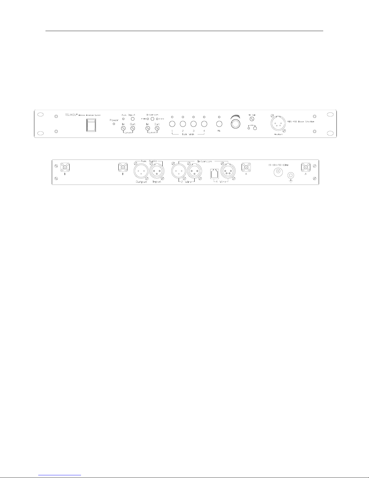
1) Front Panel
1. Connector:
Headset: Pin1, Pin2: Microphone balance input
Pin3, Pin4: Earphone balance output
2. Press Button:
Mic: Headset Microphone ON/OFF switch
2W/4W: 2 wire/ 4 wire intercom connector selection switch
Aux.: Aux Audio input ON/OFF switch
VOX: Microphone Voice control function switch
CH1: Wireless belt pack Channel 1 control switch
CH2: Wireless belt pack Channel 2 control switch
CH3: Wireless belt pack Channel 3 control switch
CH4: Wireless belt pack Channel 4 control switch
3. Adjustment Knob
Aux. In Level: Adjust Aux. input Audio signal level
Aux. Out Level: Adjust Aux. output Audio signal level
Intercom In level: Adjust intercom input connector audio signal level
Intercom Out level: Adjust intercom output connector audio signal level

TELIKOU MDS-400 Wireless Main Station
2
Mic Gain: Adjust headset Microphone gain
Volume: Adjust the headset audio
4. Switch
Power: Main station Power switch
5. Indication Led Light
Power LED: Power indication LED light.
ON: Power on,
OFF: Power off
4-wire LED: 4-wire device connector enable LED indicator.
ON: 4-Wire device connector is enabling
OFF: 4-wire device connector is disabling
2-wire LED: 2-wire device connector enable LED indicator.
ON: 2-Wire device connector is enabling
OFF: 2-wire device connector is disabling
CH1/2/3/4 LED: 1. Channel switch indicator.
On: Channel on
Off: Channel off
2. When channel switch is off, if main station detected any belt
-pack microphone is turned on, this indicator flash fast.
(1s on, 1s off)
MIC LED: Main station headset indication LED light
ON: Microphone on
OFF: Microphone off
VOX LED: Microphone Voice control function Indication LED light
ON: VOX function is on
OFF: VOX function is off
Aux. LED: Auxiliary input indication LED light
ON: AUX audio signal input is enabling.
OFF: AUX audio signal input is disabling.

TELIKOU MDS-400 Wireless Main Station
3
2) Rear Panel
1. Connecting socket
4-wire Connector: 4-wire device connector.
(RJ11 and XLR-4F are parallel connected).
Pin1/Pin2: Balanced audio input
Pin3/Pin4: Balanced audio output
2-wire Connector: 2-wire device connector.
(XLR-3F and XLR-3M are loop through)
Pin1: Common
Pin2: null
Pin3: audio
Aux Audio In: Aux input audio signal input connector
Pin1: Common
Pin2: audio +
Pin3: audio –
Aux Audio Out: Aux output audio signal connector.
Pin1: Common
Pin2: audio +
Pin3: audio –
Antenna: SMA antenna connector.
CH1, CH2: Group B;
CH3, CH4: Group A
Power: Power connector. 15-18VAC (VDC), 1.5A, VAC: 50-60Hz
 Loading...