

Page 1
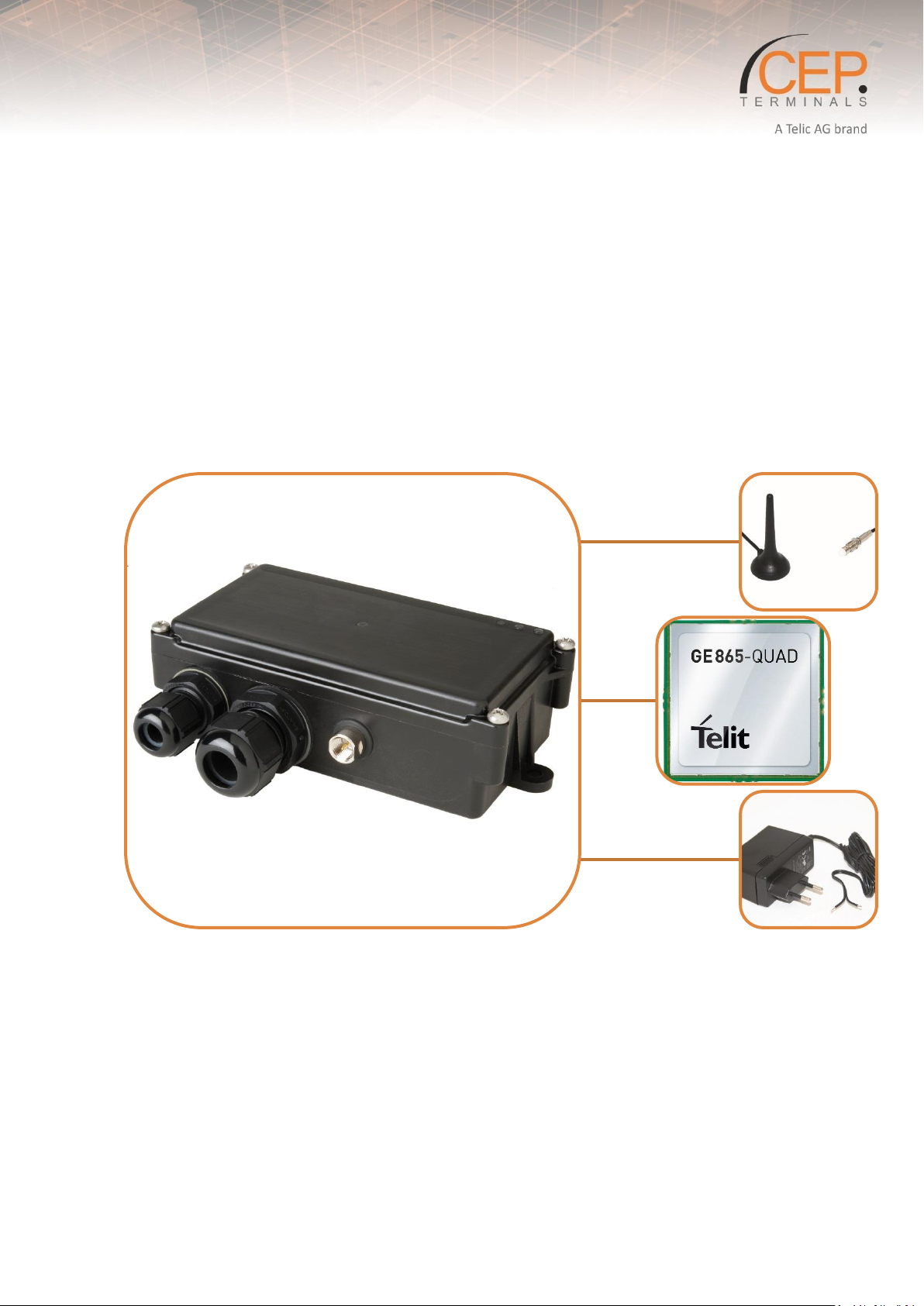
STD32/35
User Manual
Revision 3.0
Page 2

Important information
This technical description contains important information for the installation and use of the STD3X.
Read it carefully before you start working with the STD3X.
The warranty will be void should damage occur due to non-compliance with these instructions. We
cannot accept any responsibility for consequential loss.
We cannot be held responsible for material loss or personal injury that is due to non-compliance with
the safety instructions. The warranty will be void in such circumstances.
Telic reserves the right to change the included information without notice and does not take
responsibility for errors in the document and/or for any missing information.
2
Page 3

Table of Contents
Important information ...................................................................................................................................................... 2
1 General Information ................................................................................................................................................. 6
1.1 Contact for Support .......................................................................................................................................... 6
1.2 Conventions Used in this Manual ..................................................................................................................... 6
1.3 Related Documentation .................................................................................................................................... 7
1.4 Abbreviations .................................................................................................................................................... 8
1.5 Revision History................................................................................................................................................. 8
2 Product Description ................................................................................................................................................ 10
2.1 Overview ......................................................................................................................................................... 10
2.1.1 Overview STD32 ...................................................................................................................................... 10
2.1.2 Ovierview STD35 ..................................................................................................................................... 12
2.2 Identification ................................................................................................................................................... 13
2.2.1 STD32 Type Label .................................................................................................................................... 13
2.2.2 Physical Dimensions and Weight ............................................................................................................ 13
2.2.3 STD35 Type Label .................................................................................................................................... 14
2.2.4 Physical Dimensions and Weight ............................................................................................................ 14
2.3 Product Features and Technical Data for STD3X ............................................................................................ 14
2.4 Telic Certified Accessories ............................................................................................................................... 17
3 Safety and Product Care ......................................................................................................................................... 18
3.1 Audience and Intended Use ............................................................................................................................ 18
3.2 Safety instructions .......................................................................................................................................... 18
3.3 General precautions ........................................................................................................................................ 19
3.4 SIM card precautions ...................................................................................................................................... 20
3.5 Antenna precautions ....................................................................................................................................... 20
3.6 Storage Conditions .......................................................................................................................................... 20
3.7 Power Connector ............................................................................................................................................ 20
3.8 Antenna Connector ......................................................................................................................................... 21
3.9 SIM card reader ............................................................................................................................................... 21
3.10 Status LEDs (one green, one yellow, one red) ................................................................................................ 21
3.11 Power consumption during Regular Operation .............................................................................................. 22
4 Installation of the device......................................................................................................................................... 23
3
Page 4

4.1 Where to install the device ............................................................................................................................. 23
4.1.1 Environmental conditions ....................................................................................................................... 23
4.1.2 GSM Signal strength ................................................................................................................................ 23
4.1.3 Connection of components to the STD3X Terminal ................................................................................ 23
4.1.4 Network and Subscription....................................................................................................................... 23
4.2 How to install the device................................................................................................................................. 23
4.2.1 General preparations .............................................................................................................................. 24
4.2.2 Preparing the Device ............................................................................................................................... 24
4.2.3 Connecting the battery (STD35 only) ...................................................................................................... 25
4.2.4 Call-based Configuration ......................................................................................................................... 25
4.3 Antenna ........................................................................................................................................................... 25
4.3.1 General .................................................................................................................................................... 25
4.3.2 Antenna placement ................................................................................................................................. 26
4.3.3 The antenna cable ................................................................................................................................... 26
4.3.4 Possible communications disturbances .................................................................................................. 26
5 Updating the Firmware of the STD3X ..................................................................................................................... 27
6 FAQ and Troubleshooting ....................................................................................................................................... 28
6.1 Some troubleshooting hints ............................................................................................................................ 28
6.2 FAQs ................................................................................................................................................................ 28
6.2.1 How do I know the version of my STD32/35 V4 and STD32/35 V5 ........................................................ 28
6.2.2 Can a camera be connected to the STD3X? ............................................................................................ 28
6.2.3 Set or change Master ID? ........................................................................................................................ 28
6.2.4 Set Master ID via Phone Call ................................................................................................................... 29
6.2.5 Clip-List - Add and delete phone number ............................................................................................... 29
6.2.6 Usage of the SIM card and general preparation ..................................................................................... 30
6.2.7 What are the differences between STD32 & STD35? ............................................................................. 30
6.2.8 Which temperature sensor I can connect to the analogue inputs of the STD3X? .................................. 31
6.2.9 Which Software is installed on my STD Device? ..................................................................................... 31
6.2.10 The device doesn't send any SMS, but it is accessible on the mobile network ...................................... 31
6.2.11 Sending E-Mails doesn't work ................................................................................................................. 31
6.2.12 Why does my device have no GSM reception? ...................................................................................... 31
4
Page 5

Table Overview
Table 1: Abbreviation ........................................................................................................................................................ 8
Table 2: Documentation Change Log ................................................................................................................................ 9
Table 3: Positioning of the connectors on the STD32 ..................................................................................................... 11
Table 4: Available Connectors of the STD35 ................................................................................................................... 12
Table 5: STD32 Feature Overview ................................................................................................................................... 15
Table 6: STD35 Feature Overview ................................................................................................................................... 16
Table 7: Accessories List .................................................................................................................................................. 17
Table 8: Power consumption for STD32 and STD35 at 12V. ........................................................................................... 22
Table 9: Troubleshooting ................................................................................................................................................ 28
Figure Overview
Figure 1: Positioning of the connectors on the STD32 ................................................................................................... 10
Figure 2: Positioning of the connectors on the STD35 ................................................................................................... 12
Figure 3: Connected Power supply 230V at the STD32 (EU-plug) ................................................................................... 21
Figure 4: Connecting the battery (STD35 only) ............................................................................................................... 25
5
Page 6
Chapter
Description
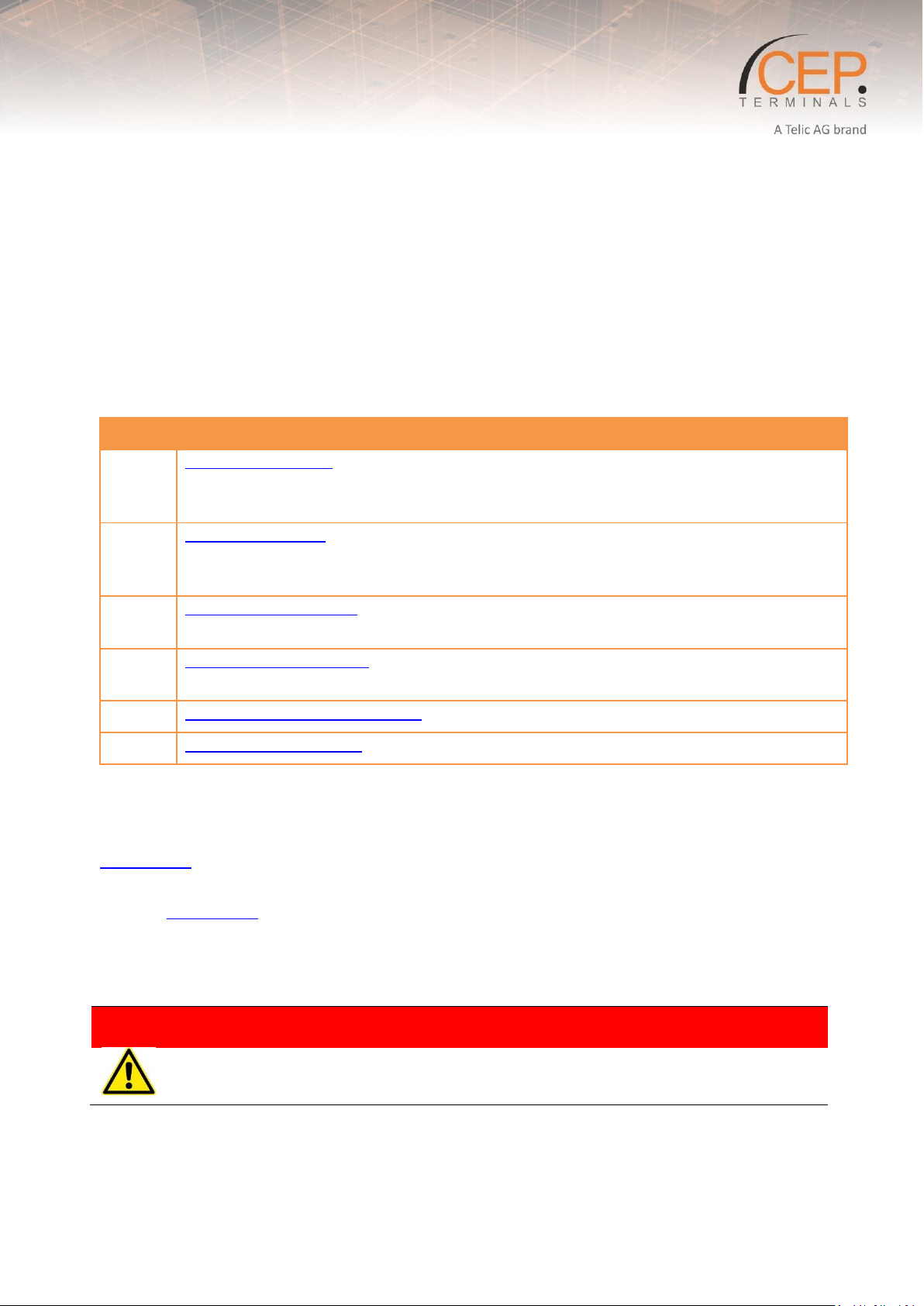
1
General Information provides basic information such as the conventions for the
warning levels, applicable related documentations, used abbreviations, a revision
history and contact information.
2
Product Description provides a brief overview about the mechanical specification of
the product (including size and weight) as well as an overview of the functions and
features of the device as well as the available accessories.
3
Safety and Product Care addresses the audience for this manual, the indented use of
this device and safety-related information important to read before using the device.
4
Installation of the Device provides important instructions about how to install the
device for the M2M application.
5
Updating the Firmware of the STD explains how to update the STD3X.
6
FAQ and Troubleshooting gives an answer to the most common problems.
Warning
Warnings against hazards that may result directly in serious injuries or death in case of
non-observance.
1 General Information
Thank you very much for purchasing our STD3X telemetry device!
The STD3X enables the user to remotely switch ON or OFF electronic devices and to receive alarm
messages via (SMS). You can switch devices either with an SMS or using a simple voice call. Alarm
messages (SMS) can be received with any mobile phone supporting SMS functionality. With the STD3X
you can also receive alarm messages by E-Mail.
We wish you success in using your new STD3X!
This User Manual consists of the following chapters:
1.1 Contact for Support
Please submit your request to TELIC AG customer support using the following online form:
www.telic.de
Information about Telic AG, products and accessories, including FAQs, are available from the following
web site: www.telic.de
1.2 Conventions Used in this Manual
The following conventions for warning levels are used in this manual:
6
Page 7
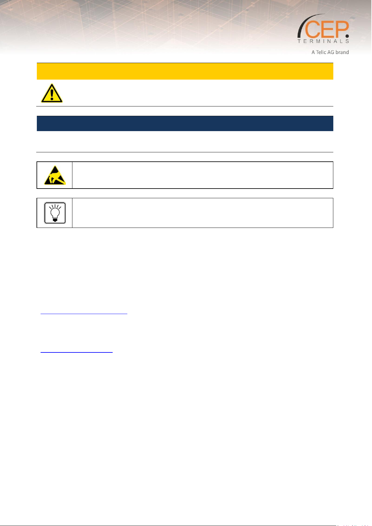
Caution
Warnings against hazards that may result in injuries in case of non-observance.
NOTICE
Warnings against hazards that may result in material damage in case of non-observance.
Indicates that the device can be damaged by electrostatic discharge.
This note contains helpful suggestions or references to material not covered in the
document.
1.3 Related Documentation
Please consult the download zone of the Telic AG website for additional documents related to STD3X, such as
the Configuration Manual. Note that such type of documents can be accessed online only after you have
registered on our website and agreed with our terms of use. Please follow this link to register for a user
account:
www.telic.de/en/nda-reg-form
or use the following link to login if you already have a valid user account:
www.telic.de/en/en-login
7
Page 8
Abbreviation
Explanations
CSD
Circuit Switched Data
DCE
Data Circuit Terminating Equipment
DTE
Data Terminal Equipment
GPRS
General Packet Radio Service
GSM
Global System for Mobile Communication
ME
Mobile Equipment
MO
Mobile Originated
MS
Mobile Station
PDU
Protocol Data Unit
RF
Radio Frequency
SIM
Subscriber Identity Module
SMS
Short Message Service
TA
Terminal Adapter
TE
Terminal Equipment
TS
Telecom Services
Revision
Datum
Changes
Rev. 1.0
16th Dec 2010
Original file
Rev.1.1
14th Jan 2011
Update
Rev 1.2
23rd Jan 2011
Added Configuration Tool
Rev 1.3
6
th
June 2011
Minor Corrections
Rev 1.4
9th June 2011
Corrected relay voltage mistake
Rev 1.5
10th December 2013
Change from Telic to CEP,
Complete Update
Rev. 2.0
15th Jan 2015
Content adapted to new hardware
Rev 2.1
31st March 2015
Several clarifications throughout the document.
Rev. 2.2
11th June 2015
Update Status LEDs, E-Mail Commands, Section 4 ,
6.2,7.1
Rev 2.3
12th August 2015
Update Section 6.1 CLIP commands
Rev 3.0
22th August 2017
Update of the Layout.
Splitting the User Manual in Configuration Manual and
User Manual.
Revision
Datum
Changes
Rev. 1.0
16th Dec 2010
Original file
Rev.1.1
14th Jan 2011
Update
Rev 1.2
23rd Jan 2011
Added Configuration Tool
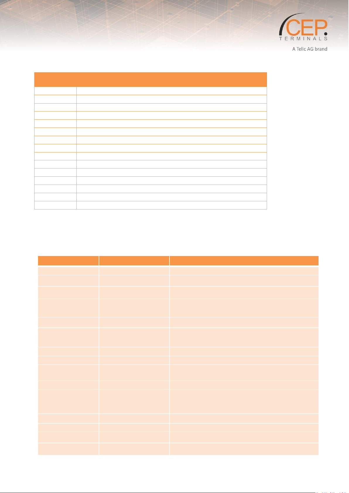
1.4 Abbreviations
Table 1: Abbreviation
1.5 Revision History
8
Page 9
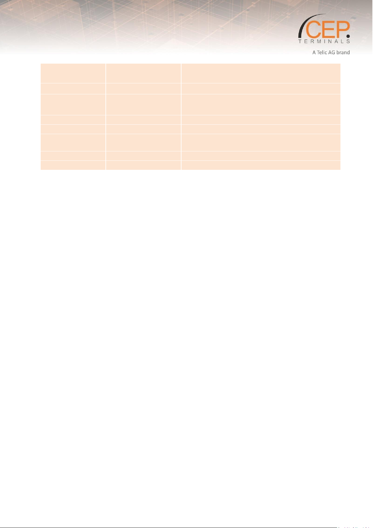
Rev 1.3
6
th
June 2011
Minor Corrections
Rev 1.4
9th June 2011
Corrected relay voltage mistake
Rev 1.5
10th December 2013
Change from Telic to CEP,
Complete Update
Rev. 2.0
15th Jan 2015
Content adapted to new hardware
Rev 2.1
31st March 2015
Several clarifications throughout the document.
Rev. 2.2
11th June 2015
Update Status LEDs, E-Mail Commands, Section 4 ,
6.2,7.1
Rev 2.3
12th August 2015
Update Section 6.1 CLIP commands
Rev 3.0
24th October 2017
Merged STD32 and STD35 User Manual
T
a
b
l
e
2
:
D
o
c
u
m
e
ntation Change Log
9
Page 10
Please note that the configuration tool does not support the STD3X anymore.
The configuration should be done by a GSM mobile phone or SMS capable
software.
2 Product Description
2.1 Overview
The STD3X is a telemetry module which is easy to install and simple to use. It can be configured using
any GSM mobile phone, SMS capable software.
With the STD35 you can control five relays and monitor the status of three digital and two analog inputs
with one or several standard mobile phones.
With the STD32 you can control two 5A relays and monitor the status of two digital inputs with one or
several standard mobile phones.
Apart from the STD3X you only need a valid SIM Card from any network provider (GSM850 / 900 / 1800
or 1900 MHz).
Please note: Only use standard [1.8V / 3V] SIM Cards!
2.1.1 Overview STD32
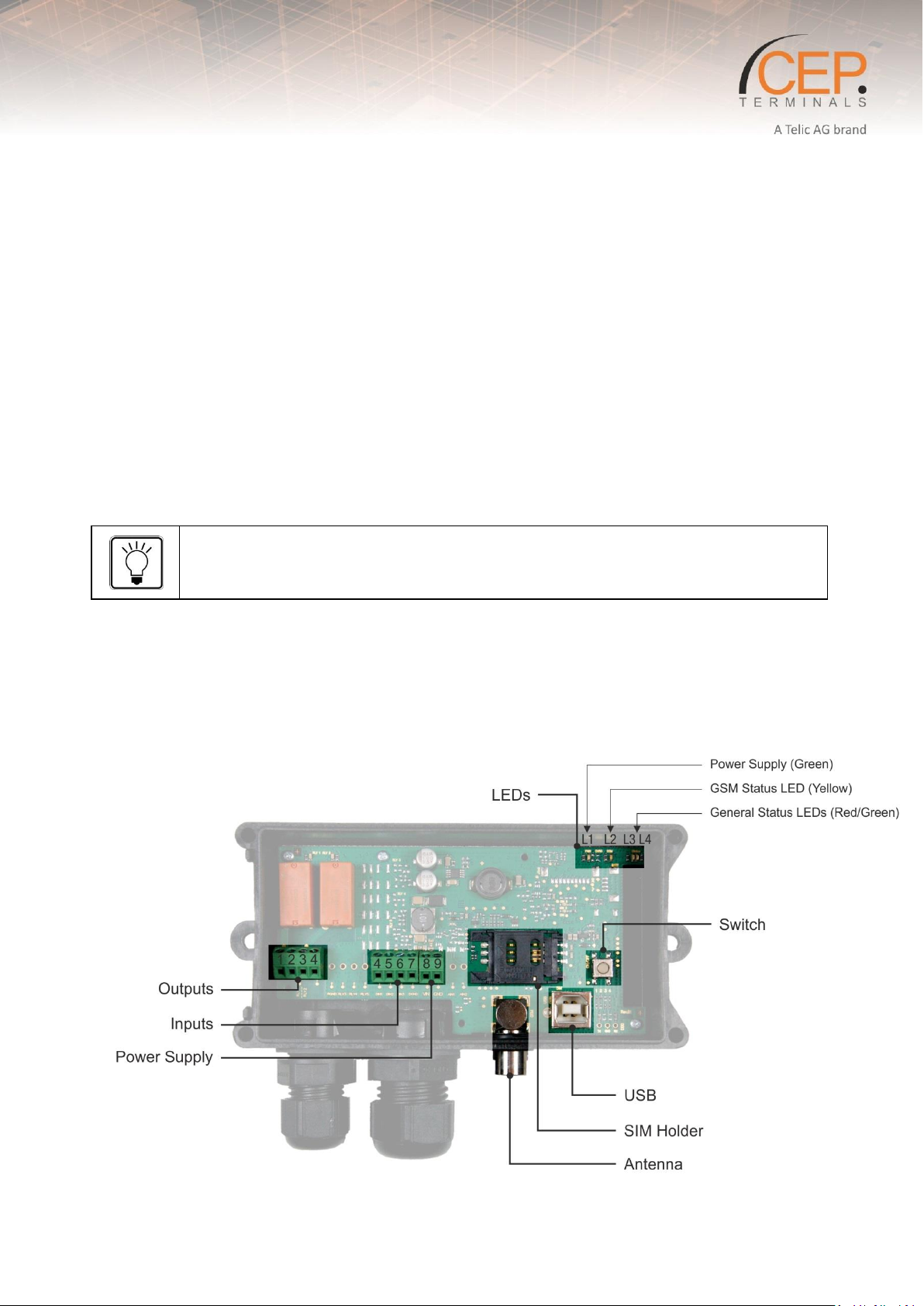
The pictures below show the mechanical design of the STD3X Terminal along with the positions of the
different connectors and mounting holes. The STD3X Terminal case is made of durable PC/ABS plastic.
Figure 1: Positioning of the connectors on the STD32
10
Page 11
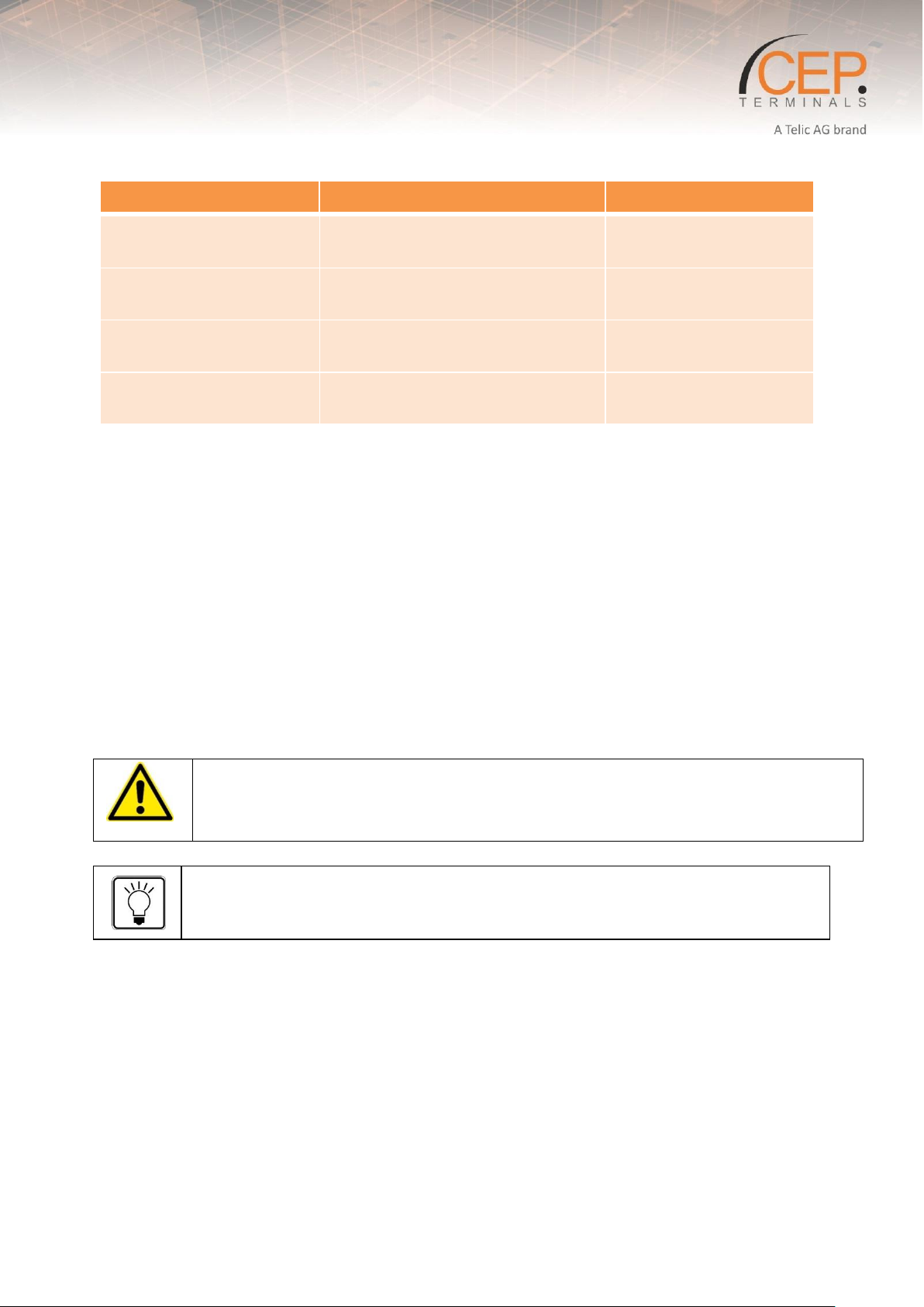
Outputs
Inputs
Power Supply
Screw 1: RLY1 Contact
1
Screw 4: DIN1
Screw 8: VIN
Screw 2: RLY1 Contact
2
Screw 5: DIN2
Screw 9: GND
Screw 3: RLY2 Contact
1
Screw 6: Not used
Screw 4: RLY2 Contact
2
Screw 7: Common ground for
inputs 1 & 2 (GND)
Please observe the maximum output voltage of the relays and the maximum input
voltage of the inputs! (Refer to Section 2.3 Product Features and Technical Data)
A hardware reset of the device is performed if the “switch” is pressed for more than 7
seconds.
Table 3: Positioning of the connectors on the STD32
Please note the following instructions:
Screw terminal “Outputs”: Here, electrical loads are connected to the respective relay. By
activating an output, the respective relay RLY 1 or RLY 2 establishes an electrical connection
between contact 1 and 2. Please consider the limit values for all RLY’s (see article 2.3 Product
Features and Technical Data)
Screw terminal “Inputs”: The inputs are activated as soon as a voltage is applied within the
specified range between the terminals (e.g. DIN1 and GND refer to Section 2.3 Product Features
and Technical Data). The analog inputs (terminals F & G) use the ground potential of the power
supply (i.e., terminal E).
Screw terminal “Power Supply”: Power supply is applied on screw D (VIN ) and screw E (GND).
The used terminal blocks are designed for cables with a cross-section of 0.08mm² to 1,3mm² (both
single core and multistring).
The (FME-Female) connector “Antenna” is used to connect the GSM antenna.
11
Page 12
Outputs
Inputs
Power Supply
Screw 1: RYL1 Contact 1
Screw 9: DIN1
Screw D: VIN
Screw 2: RLY1 Contact 2
Screw A: DIN2
Screw E: GND
Screw 3: RLY2 Contact 1
Screw B: DIN3
Screw 4: RLY2 Contact 2
Screw C: DGND
Screw 5: RGND
Screw F: AIN1
Screw 6: RLY3
Screw G: AIN2
Screw 7: RLY4
Screw 8: RLY5
2.1.2 Ovierview STD35
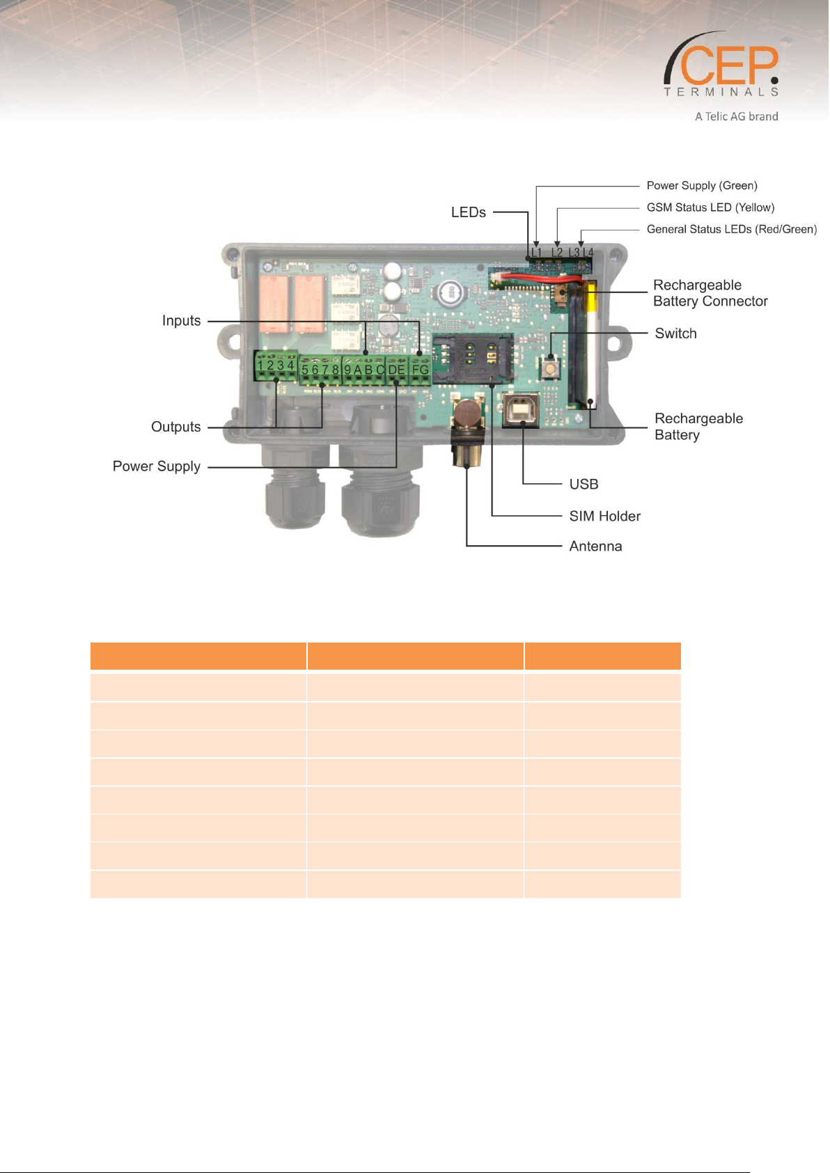
Figure 2: Positioning of the connectors on the STD35
Table 4: Available Connectors of the STD35
12
Page 13
Please observe the maximum output voltage of the relays and the maximum input
voltage of the inputs! (Refer to Section 2.3).
A hardware reset of the device is performed if the “switch” is pressed for more than 7
seconds.
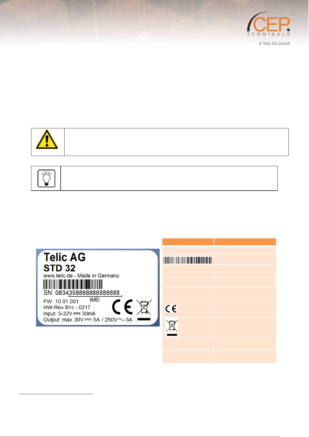
Label
Description
S/N
Serial number
1
Serial number
IMEI
International Mobile
Equipment Identity
FW
GSM firmware version
HW-Rev.
Hardware Revision
Number + Production date
CE conformity mark
Disposal in accordance
with European Directive
2002/96/CE
Input
Defines the minimum and
maximum power supply
Output
Defines the maximum
output
Please note the following instructions:
Screw terminal “Outputs”: Here, electrical loads are connected to the respective relay.
Screw terminal “Inputs”: The inputs are activated as soon as a voltage is applied within the
specified range between the terminals (e.g. Input 1 and GND; refer to Section Fehler! Verweisquelle
konnte nicht gefunden werden., “Fehler! Verweisquelle konnte nicht gefunden werden.”). The
analog inputs (terminals F & G) use the ground potential of the power supply (ie, terminal E).
Screw terminal “Power Supply”: Power supply is applied on screw D (VIN +) and screw E (GND).
The used terminal blocks are designed for cables with a cross-section of 0.08mm² to 1,3mm² (both
single core and multistring).
The (FME-Female) connector “Antenna” is used to connect the GSM antenna.
2.2 Identification
2.2.1 STD32 Type Label
On the bottom of the device, you will find the type label.
2.2.2 Physical Dimensions and Weight
13
Page 14
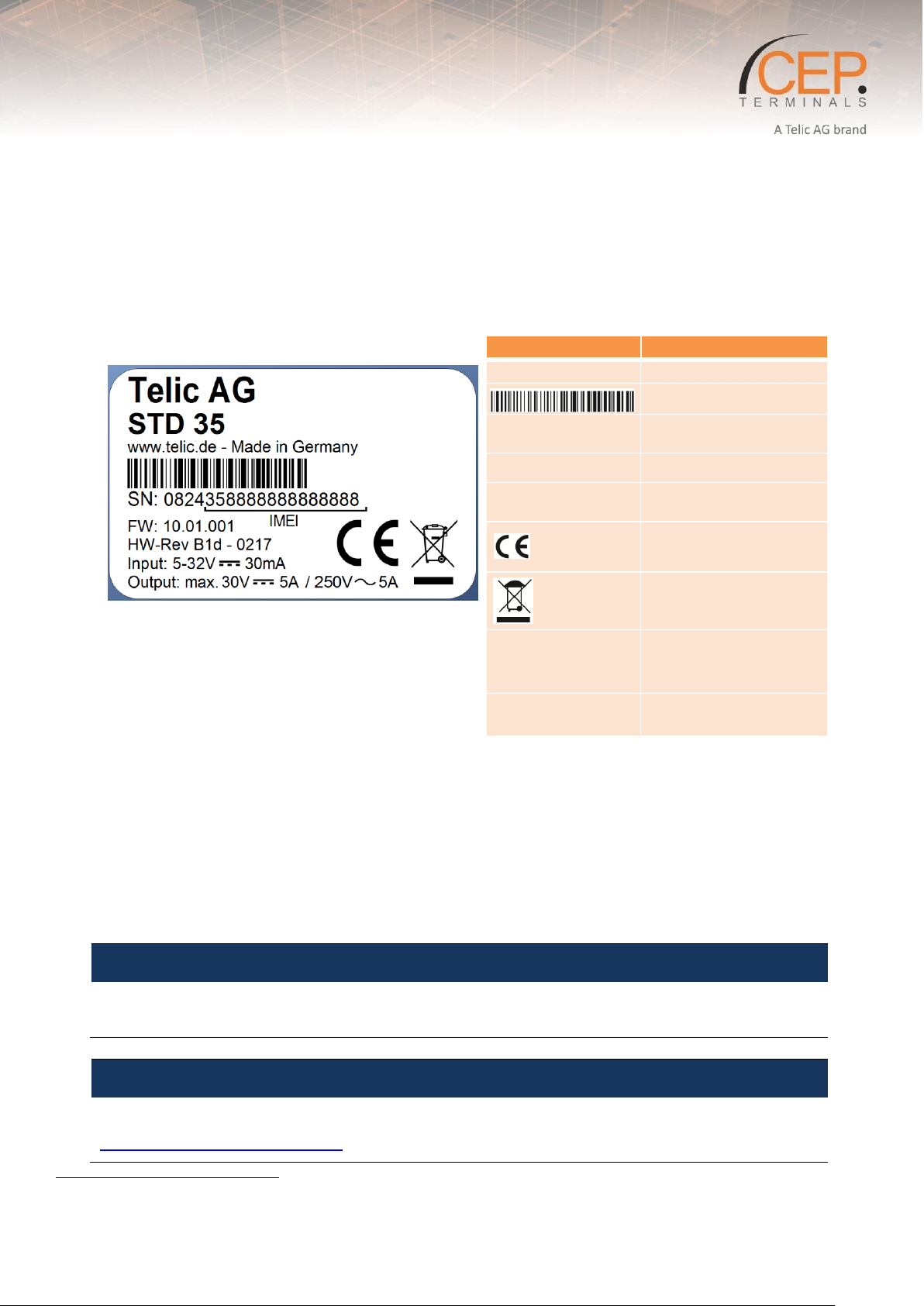
Label
Description
S/N
Serial number
2
Serial number
IMEI
International Mobile
Equipment Identity
FW
GSM firmware version
HW-Rev.
Hardware Revision
Number + Production date
CE conformity mark
Disposal in accordance
with European Directive
2002/96/CE
Input
Defines the minimum
and maximum power
supply
Output
Defines the maximum
output
NOTICE
Telic AG may, at any time and without notice, make changes or improvements to the products and
services offered and / or cease producing or commercializing them.
NOTICE
Optional Features are not assembled by default, please contact our Sales Team at
http://www.telic.de/en/contact-us to clarify the details of ordering terminal variants.
STD32:
Overall dimensions: 150 x 65 x 45 mm
Weight: approx. 230g
2.2.3 STD35 Type Label
On the bottom of the device, you will find the type label.
2.2.4 Physical Dimensions and Weight
STD35:
Overall dimensions: 150 x 65 x 45 mm
Weight: approx. 230g
2.3 Product Features and Technical Data for STD3X
14
Page 15
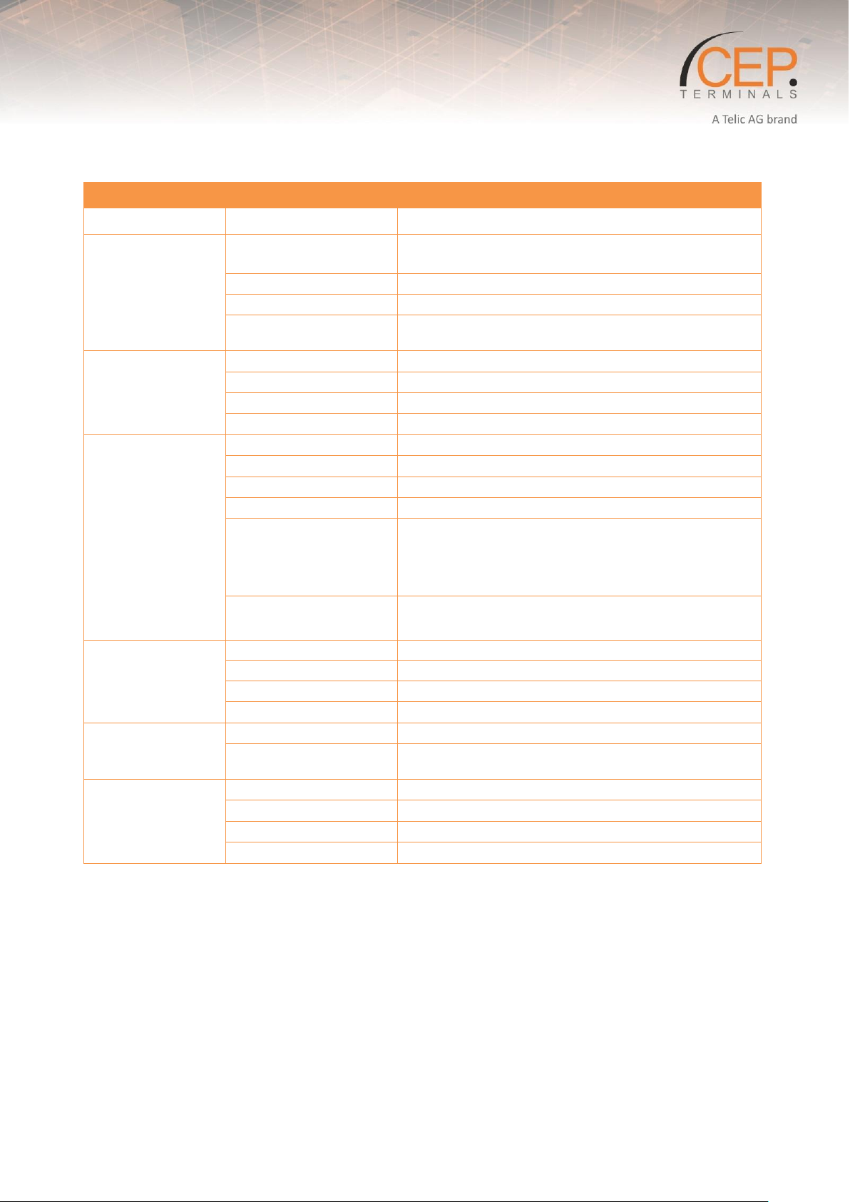
STD32
Category
Features
Details
Air Interface
2G Frequency Band
GSM / GPRS Quad Band; EGSM 850/900/1800/1900
MHz
GPRS Class
Class 10
GPRS Features
E-mail
Output Power
Class 4 (2W @ 850/900 MHz)
Class 1 (1W @ 1800/1900 MHz)
Hardware Features
Memory
SIM Card Holder
1x (1,8/3 Volt)
LEDs
4x (Power / GSM / 2x IO Status)
Type Approvals
CE
Interfaces /
Connectors
Antenna
1x FME Male
1-Wire
Optional (Instead of 1 AIN)
USB 2.0
1x (USB-B connector; internal)
Analog Inputs
2x (12 bit; max. 32V)
Outputs
Max. output current Output 1&2: 5A
Max. output voltage Output 1&2: 30V DC; 250V AC
Max. output current Output 3&4 and 5: 30V DC
Max. output voltage Output 3&4 and 5: 30V DC
Switching Capacity
(Relays)
2x (5A/250V AC, 5A/30V DC, resistive load)
Software
SW Update
DOTA / USB
Device Configuration
SMS
Status / Event Reporting
SMS / SMTP E-Mail
SMTP E-Mail
Transmission of Event Data
Power Management
Voltage Range
5V - 32V DC
Power Consumption
(Typical)
~14 mA
Hardware
Characteristics
Operating Temperature
-30°C to +75°C
Recharging Temperature
0°C to +45°C
Dimensions
150x65x45 mm
Weight
230g
Table 5: STD32 Feature Overview
15
Page 16
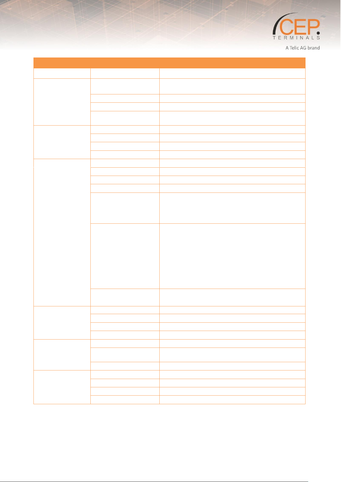
STD35
Category
Features
Details
Air Interface
2G Frequency Band
GSM / GPRS Quad Band; EGSM 850/900/1800/1900
MHz
GPRS Class
Class 10
GPRS Features
E-mail
Output Power
Class 4 (2W @ 850/900 MHz)
Class 1 (1W @ 1800/1900 MHz)
Hardware Features
Memory
SIM Card Holder
1x (1,8/3 Volt)
LEDs
4x (Power / GSM / 3x IO Status)
Type Approvals
CE
Interfaces /
Connectors
Antenna
1x FME Male
1-Wire
Optional (Instead of 1 AIN)
USB 2.0
1x (USB-B connector; internal, for configuration)
Analog Inputs
2x (12 bit; max. 32V)
Outputs
Max. output current Output 1&2: 5A
Max. output voltage Output 1&2: 30V DC; 250V AC
Max. output current Output 3&4 and 5: 30V DC
Max. output voltage Output 3&4 and 5: 30V DC
Digital Inputs
3x (galvanically isolated; common external
ground)
Input voltage (digital inputs)
logic 1 (threshold >7V): max 30V
logic 0 (threshold <1,5V): min 0V
Input voltage (analog inputs)
Max (30V)
Min (0V)
Switching Capacity
(Relays)
2x (5A/250V AC, 5A/30V DC, resistive load)
3x (1A / 30 V DC)
Software
SW Update
DOTA / USB
Device Configuration
SMS
Status / Event Reporting
SMS / SMTP E-Mail
SMTP E-Mail
Transmission of Event Data
Power Management
Voltage Range
5V - 32V DC
Power Consumption
(Typical)
~11 mA
Internal Battery
660 mAh (LiPo; backup)
Hardware
Characteristics
Operating Temperature
-30°C to +75°C
Recharging Temperature
0°C to +45°C
Dimensions
150x65x45 mm
Weight
230g
Table 6: STD35 Feature Overview
16
Page 17
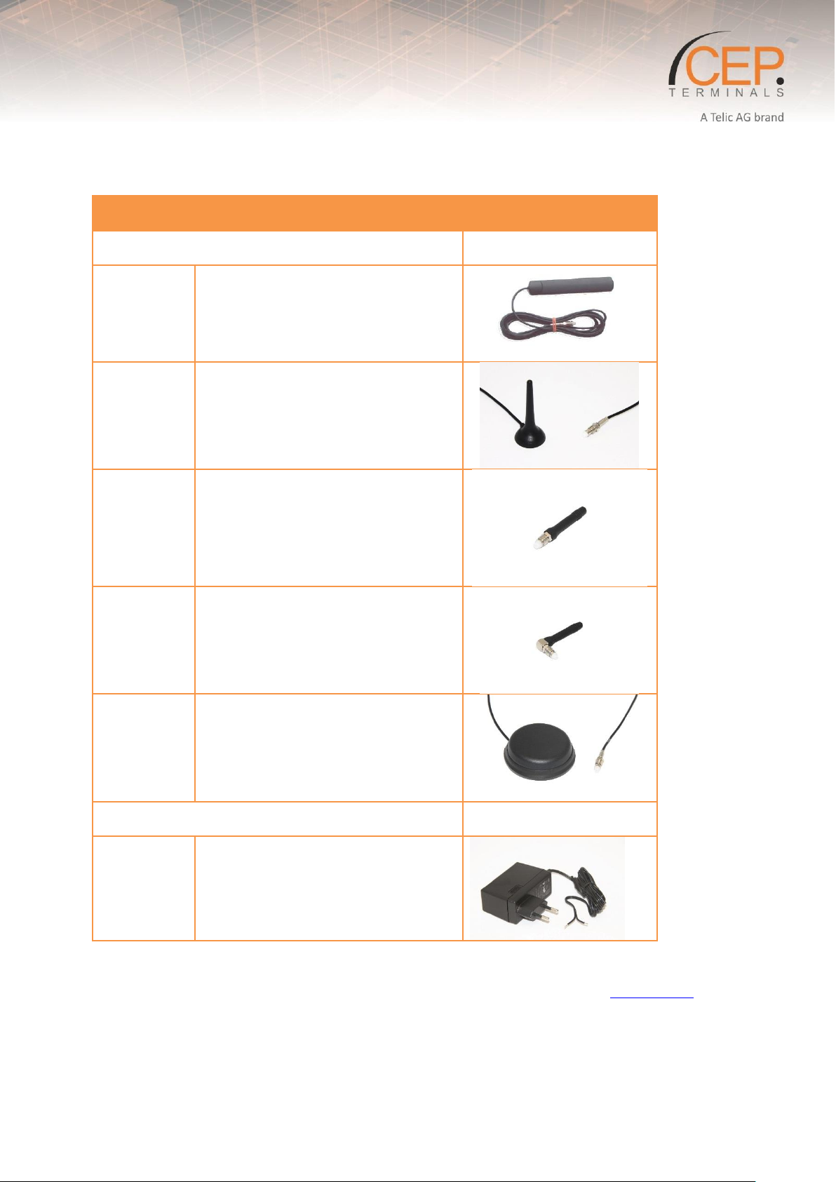
Art-Nr.
Description
Antennas
Picture
12020
Patch Antenna; FME female connector,
self-adhesive, waterproof,
GSM: 900, 1800, 1900 MHz; UMTS:
2100 MHz
12021
Magnetic Antenna; FME female
connector,
GSM: 900, 1800 MHz, UMTS: 2100 MHz
12019
Stub Antenna; FME female,
GSM: 900/1800 MHz; UMTS 2100 MHz
12016
Rectangular Antenna; FME female,
GSM: 900 / 1800 MHz; UMTS: 2100
MHz (Terminal is shipped by default
with a rectangular antenna)
12006
Roof-mount antenna; FME female
waterproof,
900 / 1800 / 1900 / 2100 / 2400 MHz
Others
Picture
14001
Power supply 230V for STD3X (EU-plug)
2.4 Telic Certified Accessories
Table 7: Accessories List
Please contact your distributor or Telic AG for availability or check Telic’s webpage www.telic.de.
17
Page 18
NOTICE
If these instructions are ignored, Telic AG will not assume responsibility for any damages that are
incurred. Telic AG may refuse warranty claims where evidence of product misuse is found.
Therefore only touch the STD3X on the housing or connectors and avoid touching the
components on the board.
When using products which are exposed to electric voltage the valid VDE-regulations have to be
observed. Especially VDE 0100, VDE 0550/0551, VDE 0700, VDE 0711 and VDE 0860 are
applicable.
3 Safety and Product Care
This device has been designed in accordance with state-of-the-art standards, manufactured with
utmost care using high-quality materials, and tested. Nevertheless, its use may constitute a risk to
persons or cause material damage.
The following safety instructions must be followed in order to ensure the safety of users and the device.
Please read the information in this section and the information in Section 4 Installation of the before
starting your integration work!
3.1 Audience and Intended Use
The device is designed for the remote switching of devices via the GSM network as well as the remote
retrieval of status information of the inputs and the generation of SMS messages or E-Mails after status
has changed at the inputs. A different utilization of the device other than the ones described here is not
allowed.
3.2 Safety instructions
PLEASE READ THESE SAFETY INSTRUCTIONS AND KEEP A COPY OF THEM.
The STD3X contains highly integrated components which can be damaged by electrostatic discharge if
the user would open the housing.
All wiring work has to be done in a voltage free state only.
All cables and wires which are energized and connected to the device, the module, or components
have to be checked regularly for any damage to the isolation shielding or fractures in the cables. If
the supply cables are visibly damaged the device has to be taken out of operation immediately
until the faulty cable has been exchanged.
Before putting a device into operation, it has to be clarified, whether this device or module is
appropriate for the field of application. In case of doubt ask a specialists or the manufacturer of
the device.
Please note that we are not responsible for any errors in usage or connection. Therefore we
cannot accept any responsibility for consequential loss.
Before opening the device always disconnect the mains adapter or make sure that the device is
disconnected from the power supply.
18
Page 19
Warning
When using products which are exposed to electric voltage the valid regulations have to be
observed.
Devices operating at a voltage level > 35V and which are connected to relays must be
installed only by professional technicians according to the local regulatory
requirements for safety!
Components, modules or devices have to be built into a housing before they are put into
operation. During installation they should not be connected to any power supply.
You should only use tools on components, modules, or devices if they are disconnected from the
power supply, and residual electric charge (which may still be stored in some components inside
the device) has been discharged.
When using components or modules it is necessary to strictly observe the specification given in
the corresponding description of these components.
If a description for a private end-customer does not clearly state which electric data is valid for a
component or a module, how to wire the device, which external components, or additional
devices can be connected or which parameters these components are allowed to have, a specialist
must be contacted.
Devices which operate with greater than 35 Volts have to be connected by a specialist.
Before putting the device into operation it should be checked that there is no current leakage on
the housing.
In case measurements need to be performed with an opened housing, an isolating-transformer
has to be integrated for safety reasons. Alternatively the voltage can be supplied by an
appropriate power supply which complies with the safety regulations. All wiring work has to be
done in a voltage free state only.
3.3 General precautions
Operate the STD3X only with a supply voltage between 7-32V DC and have in mind the polarity! (see
Figure 2) Use a stabilized power supply with minimum 1A output current. (We recommend using only
the original Telic power supply). If you use a mains adapter for power supply it has to conform to the
VDE regulations.
Loads connected to the device are not allowed to exceed 30 W per relay.
STD32:The maximum output voltage is 250 V AC for output 1 and 2 and 30V DC for outputs 3-4
STD35:The maximum output voltage is 250 V AC for output 1 and 2 and 30V DC for outputs 3-5
STD32: The maximum switching current for output 1 and 2 is 5A
STD35: The maximum switching current for output 1 and 2 is 5A and for outputs 3-5 it is 1A
When installing the device make sure that the supply cable has a sufficient diameter
During operation the temperature must be in the range -30° to +75° Celsius.
Protect the PCB (board) of the device from humidity, spray water and heat.
In case of condensation allow a period of about 2 hours for acclimatisation.
Do not operate the device in areas where inflammable gas, vapours, or dust are or could be
present.
Do not expose the device to heavy vibrations.
19
Page 20
Caution! Do not touch these connectors! If you do, you may release an electrical
discharge that could damage the device or the SIM card.
The unit may only be repaired by a specialist.
Only original parts have to be used when repairing the unit. The use of differing spare parts can
cause serious material loss or personal injury.
No special positioning is required to operate the device.
3.4 SIM card precautions
Before handling the SIM card in your application, ensure that you are not charged with static electricity.
Use proper precautions to avoid electrostatic discharges.
When the SIM card hatch is opened, the SIM card connectors lie exposed under the SIM card holder.
When designing your application, the SIM card’s accessibility should be taken into account. We always
recommend that you have the SIM card protected by a PIN code. This will ensure that the SIM card
cannot be used by an unauthorized person.
3.5 Antenna precautions
Consider the risk of lightning in case the antenna is to be mounted outside. Follow the instructions
provided by the antenna manufacturer.
Never connect more than one device to a single antenna. The device can be damaged by radio frequency
energy from the transmitter of another device.
Like any mobile station, the antenna of the device emits radio frequency energy. To avoid EMI
(electromagnetic interference), you must determine whether the application itself, or equipment in the
application’s proximity, needs further protection against radio emission and the disturbances it might
cause. Protection is secured either by shielding the surrounding electronics or by moving the antenna
away from the electronics and the external signals cable.
The device and antenna may be damaged if either come into contact with ground potentials other than
the one in your application. Beware, ground potential are not always what they appear to be.
3.6 Storage Conditions
The following environmental limits must be maintained in order to safely store the terminal and ensure
that it remains functional after a maximum of 12 months:
Storage temperature STD32: -40°C to +85 °C
Storage temperature STD35: -20°C to +45 °C
3.7 Power Connector
How to connect the Connector:
Take the cables of the Power Connector and lay them through the cable openings. Open the screws of
the terminal block “VIN” and “GND”. Then connect the black/white cable into the adapter terminal
block input “GND” and tighten the screw. Insert the black cable into the adapter terminal block input
“VIN” and tighten the screw.
20
Page 21
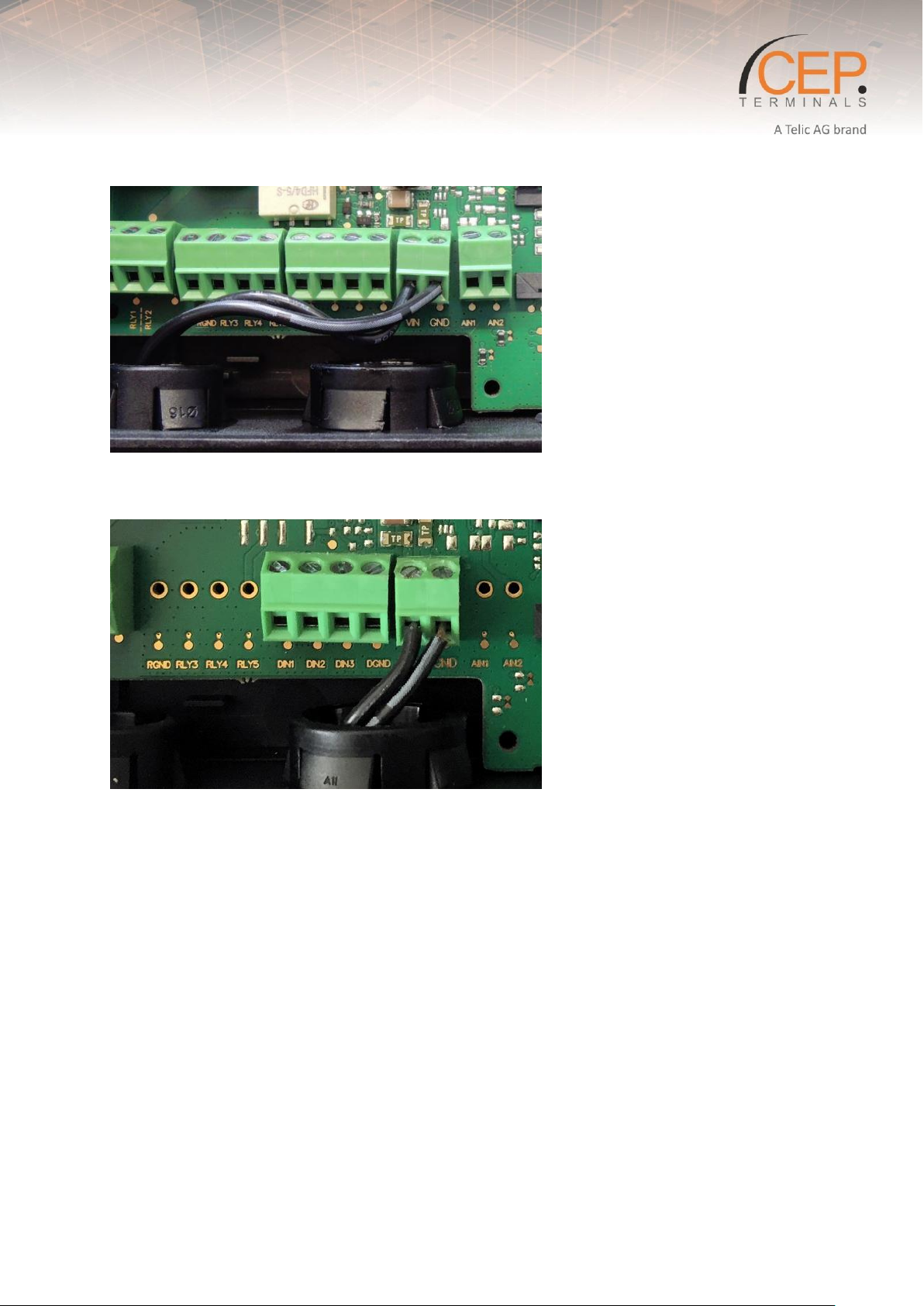
Figure 2: Connected Power supply 230V at the STD35 (EU-plug)
Figure 3: Connected Power supply 230V at the STD32 (EU-plug)
3.8 Antenna Connector
The antenna connector allows transmission of radio frequency (RF) signals between the modem and an
external customer-supplied antenna. The modem is assembled with a 50 Ohms, FME male coaxial jack.
Please take a look at our accessories (chapter 2.4 Telic Certified Accessories), to find an antenna that
fits to your application scenario.
For a specific description of the antenna requirements please go to chapter 4.3 Antenna.
3.9 SIM card reader
The Terminal is fitted with a SIM card reader designed for 1.8V and for 3V SIM cards. It is the flip-up
type which is lockable in the horizontal position and is accessed through a removable panel.
3.10 Status LEDs (one green, one yellow, one red)
Status LEDs:
The STD3X has several LEDs that indicate the operating status:
21
Page 22
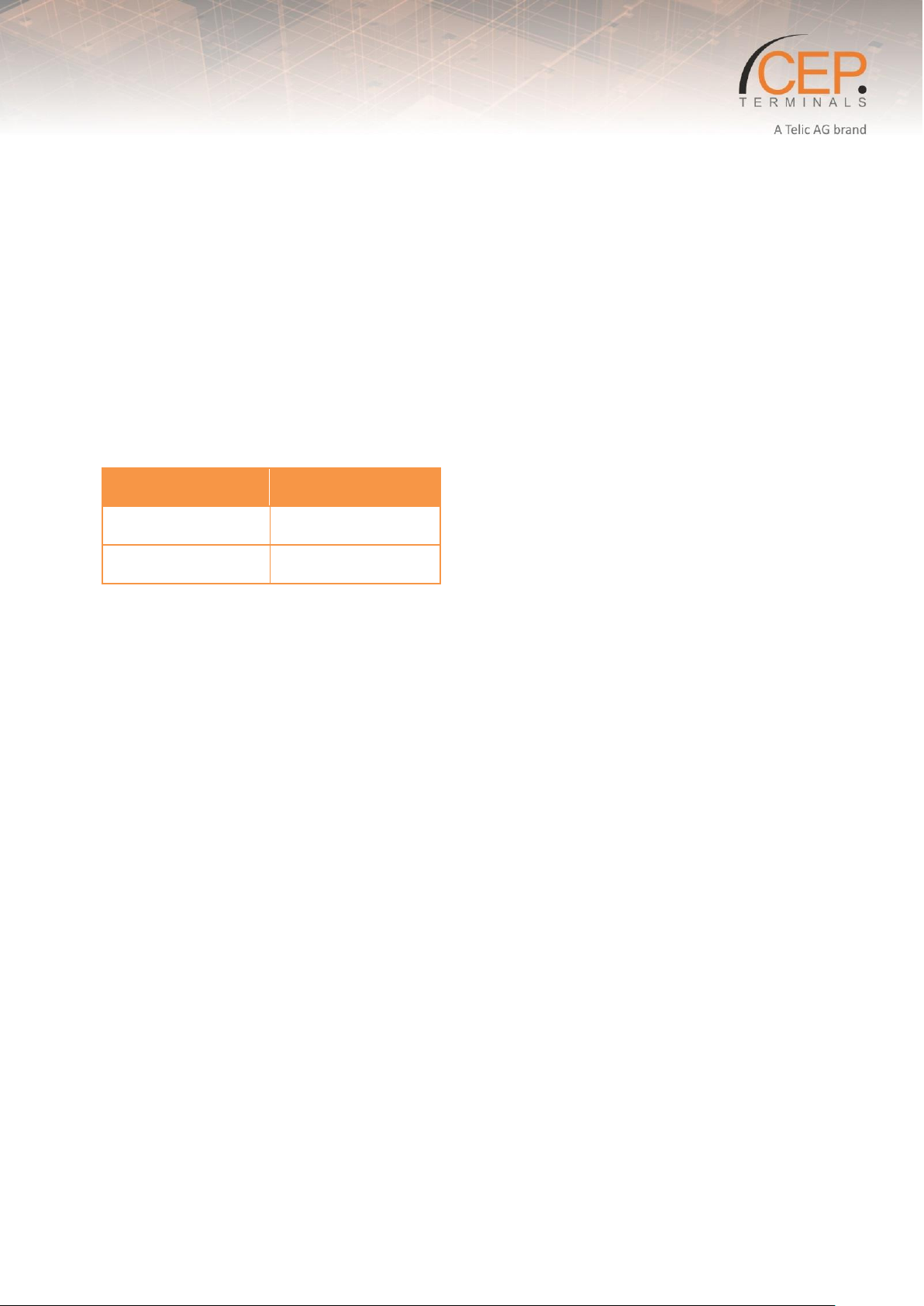
@ 12V
STD32
15mA
STD35
31mA
L1 (Green): status of the power supply. It flashes in green when the external power is applied to
the device.
L2 (Yellow): GSM status. This LED flashes once every 2 seconds for a short moment when the
device is logged into the GSM network.
L3 (Yellow): GSM status: The LED flashes faster during a DOTA Update.
L3 (Red): General Status LED. Cyclic flashing 1x every 2 seconds: the device is ready for use.L4
(Green): General Status LED. This indicates whether an administrative telephone number is
configured or not.
An alternate flashing of the LEDs L3 and L4 indicates that the device has not yet been configured.
3.11 Power consumption during Regular Operation
The following table shows you the power consumption of the Terminal.
Table 8: Power consumption for STD32 and STD35 at 12V.
22
Page 23
Before installing the modem, use an ordinary mobile telephone to check a
possible location for it. In determining the location for the modem and antenna,
you should consider signal strength as well as cable length.
4 Installation of the device
This chapter gives you advice and helpful hints on how to integrate the STD3X Terminal into your
application from a hardware perspective. Please read the information given in Section 2 Product
Description and then read the information in this section before starting your integration work.
4.1 Where to install the device
There are several conditions which need to be taken into consideration when designing your
application as they might affect the device and its function. They are:
4.1.1 Environmental conditions
The modem must be installed so that the environmental conditions stated in Section 2.3 Product
Features and Technical Data for STD3X, such as temperature, humidity and vibration are satisfied.
Additionally, the electrical specifications in Section 2.3 Product Features and Technical Data for STD3X
must not be exceeded.
4.1.2 GSM Signal strength
The device has to be placed in a way that ensures sufficient GSM signal strength. To improve signal
strength, the antenna can be moved to another position. Signal strength may depend on how close the
device is to a radio base station. You must ensure that the location at which you intend to use the
device is within the network coverage area. Degradation in signal strength can be the result of a
disturbance from another source, for example an electronic device in the immediate vicinity.
When an application is completed, you can verify signal strength by issuing the AT command AT+CSQ.
See “AT + CSQ Signal Strength”.
4.1.3 Connection of components to the STD3X Terminal
The integrator is responsible for the final integrated system. Incorrectly designed or installed external
components may cause radiation limits to be exceeded. For instance, improperly made connections or
improperly installed antennas can disturb the network and lead to malfunctions in the device or
equipment.
4.1.4 Network and Subscription
Before your application is used, you must ensure that your chosen network provides the necessary
telecommunication services. Contact your service provider to obtain the necessary information.
If you intend to use SMS in the application, ensure this is included in your (voice) subscription.
Consider the choice of the supplementary services
4.2 How to install the device
The following section provides step by step instructions to get the STD3X up-and-running without
extensive setup.
23
Page 24
If you use a SIM card with a PIN different from “0000” or “2468” in the STD3X, the
STD3X will use a “wrong” PIN. After the second attempt to power up the device
your SIM card will be blocked. In this case you need to use the “Super-PIN” or
“PUK” to assign a new PIN to your card. Please look into the user guide of your
mobile phone. There you find how to use the PUK to de-block the SIM card.
4.2.1 General preparations
You need an activated SIM card of a GSM network provider. The PIN of this card has to be set to “0000”
(4 times zero). As an alternative, you could use the PIN “2468”. To change the PIN you can use a regular
mobile phone. Please refer to your mobile phone manufacturer’s user manual for instructions on how
to change the PIN.
You can also use a SIM card without a configured PIN.
In the following we refer to the “Master Mobile” as the mobile telephone which you want to use to
switch the outputs and to configure the STD3X via calls.
The “incognito” or “private call” function of the mobile must be deactivated in order to be able to
administer the STD3X. In other words, the Master Mobile has to transmit the mobile phone number
with every call. Please refer to the user guide of your mobile telephone to change this setting.
To test the setting you can call a different mobile phone; there your phone number or name should be
displayed.
4.2.2 Preparing the Device
Please insert the SIM card into the SIM card holder on the PCB prior to connecting the supply voltage
and switching on the STD3X. To open the SIM card holder move it sideways and flip it open; insert the
card (mind the proper orientation of the card) and close it again. Move the top sideways in the opposite
direction to lock the SIM card in place.
Now please connect the GSM antenna which is part of the delivery to the proper antenna connector on
the STD3X board.
After this step, connect the external power supply using the appropriate screw terminal.
Please always observe the proper polarity of the power supply (see Figure 3/Figure 4).
24
Page 25
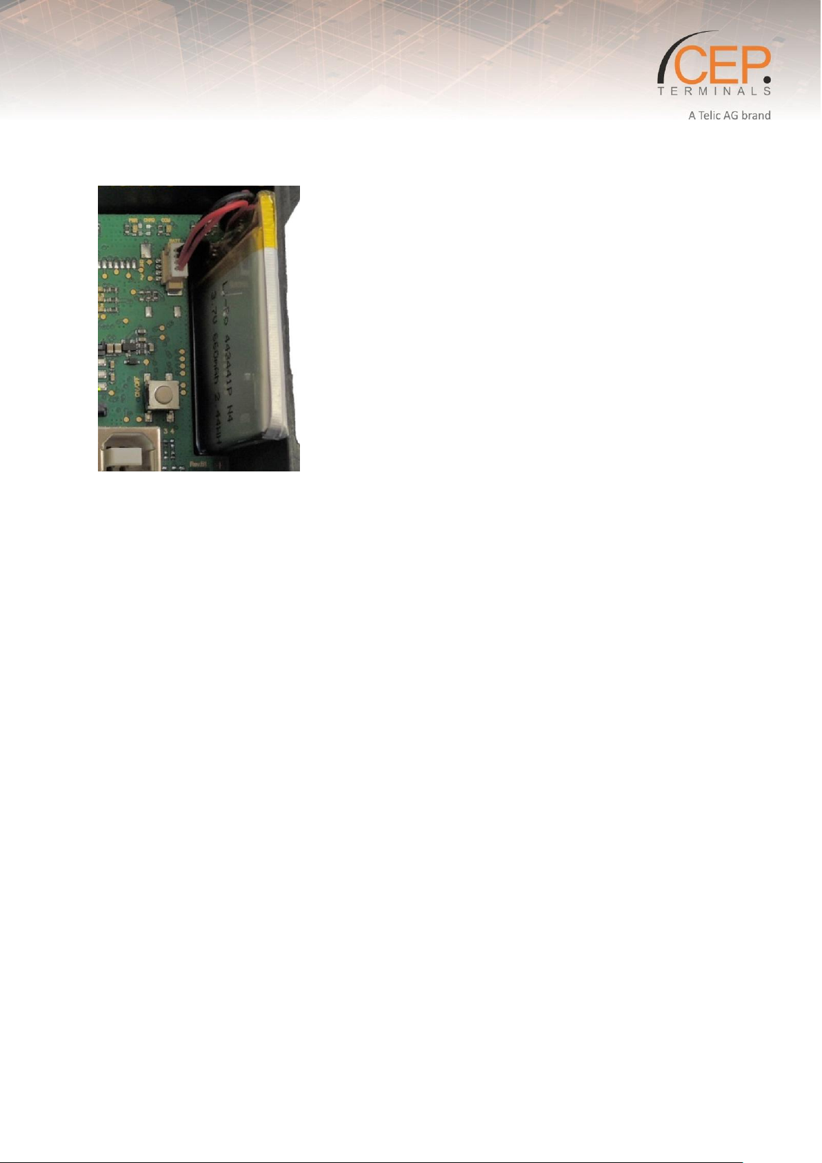
4.2.3 Connecting the battery (STD35 only)
Figure 4: Connecting the battery (STD35 only)
When delivered, the internal battery is not connected to the board (see). Please connect it to the board
with the battery connection cable to the appropriate connector as shown in Figure 4.
4.2.4 Call-based Configuration
After having connected the power supply and turned on the device for the first time, the General Status
LEDs (L3 & L4, see Figure 2) will start blinking alternately. This indicates that the device is in its original
factory settings. Shortly after that the GSM LED will be activated. Now the STD3X will automatically
attempt to connect to the GSM network. As soon as this is completed, the GSM LED will flash once
every 2 seconds.
The STD3X is now ready and can be configured.
For configuring the Master Phone please see 6.2.4 Set Master ID via Phone Call
4.3 Antenna
4.3.1 General
The antenna is the component in your system that maintains the radio link between the network and
the device. Since the antenna transmits and receives electromagnetic energy, its efficient function will
depend on:
the type of antenna (for example, circular or directional);
the placement of the antenna;
Communication disturbances in the vicinity of the antenna.
The following sections address issues concerning antenna type, antenna placement, antenna cable, and
possible communication disturbances. In any event, you should contact your antenna manufacturer for
additional information concerning antenna type, cables, connectors, antenna placement, and the
surrounding area. You should also determine whether the antenna needs to be grounded or not. Your
antenna manufacturer might be able to design a special antenna suitable for the application.
25
Page 26

4.3.2 Antenna placement
The antenna should be placed away from electronic devices or other antennas. The recommended
minimum distance between adjacent antennas, operating in a similar radio frequency band, is at least
50cm. If signal strength is weak, it is useful to face a directional antenna at the closest radio base
station. This can increase the strength of the signal received by the device. The device’s peak output
power can reach 2W. RF field strength varies with antenna type and distance. At 10cm from the
antenna the field strength may be up to 70V/m and at 1m it will have reduced to 7V/m. In general, CEmarked products for residential and commercial areas, and light industry can withstand a minimum of
3V/m.
4.3.3 The antenna cable
Use 50Ω impedance low-loss cable and high-quality 50Ω impedance connectors (frequency range up to
2GHz) to avoid RF losses. Ensure that the antenna cable is as short as possible. The Voltage StandingWave Ratio (VSWR) may depend on the effectiveness of the antenna, cable and connectors. In addition,
if you use an adapter between the antenna cable and the antenna connector, it is crucial that the
antenna cable is a high-quality, low-loss cable. Minimize the use of extension cables, connectors and
adapters. Each additional cable, connector or adapter causes a loss of signal power.
4.3.4 Possible communications disturbances
Possible communication disturbances include the following:
Noise can be caused by electronic devices and radio transmitters.
Path-loss occurs as the strength of the received signal steadily decreases in proportion to the distance
from the transmitter.
Shadowing is a form of environmental attenuation of radio signals caused by hills, buildings, trees or
even vehicles. This can be a particular problem inside buildings, especially if the walls are thick and
reinforced.
Multi-path fading is a sudden decrease or increase in the signal strength. This is the result of
interference caused when direct and reflected signals reach the antenna simultaneously. Surfaces such
as buildings, streets, vehicles, etc., can reflect signals.
Hand-over occurs as you move from one cell to another in the GSM network. Your mobile application
call is transferred from one cell to the next. Hand-over can briefly interfere with communication and may
cause a delay, or at worst, a disruption.
26
Page 27
NOTICE
Please note that the following DOTA-commands need to be send with the configured Master-Phone as
a sms.
NOTICE
Please note that for Firmware-Versions below V1.1.15 the APN settings need to be send as follows:
DOTAAPN:“internet.eplus.de“.DOTAAPNUSR:“blau“.DOTAAPNPWD:“blau“
NOTICE
Please note that you need to insert the latest version of the Firmware in the DOTA-command (quotation
marks).
DOTAFILE “std3_V1.1.15” is just an example.
We recommend to always take the latest version of the Firmware.
5 Updating the Firmware of the STD3X
A DOTA (Download Over the Air) update requires a GPRS enabled standard SIM Card
Please contact our Support team for a list of required DOTA commands
Example for DOTA with Blau SIM Card, Cetec FTP Server and a random file from the server. IMEI(last 4
Numbers of the Device)
Command 1: IMEI(Then press space and then continue the command without space like in the following
example)
DOTAUSR:“P361832f3“.DOTAPWD:“azEwagob_511“.DOTASERVER:“www.cetec.cc“.DOTAFILE:“std3_V1.1.15.tki“.
Command 2: IMEI(Then press space and then continue the command without space like in the following
example) APN:“internet.eplus.de“.APNUSR:“blau“.APNPWD:“blau“.
Set up of the APN please replace here the in the red field APN settings from your provider if not blau like
here in the example (you find the settings on the homepage of your provider).
Command 3: IMEI(Then press space and then continue the command without space like in the following
example) DOTAREQ.
Command 4: IMEI(Then press space and then continue the command without space like in the following
example) VERSION?.
All Commands have to be send by the configurated Master mobile Phone.
After Command3 you have to wait 10 minutes because in this time the device is updating. After that
Command4 can be send.
27
Page 28
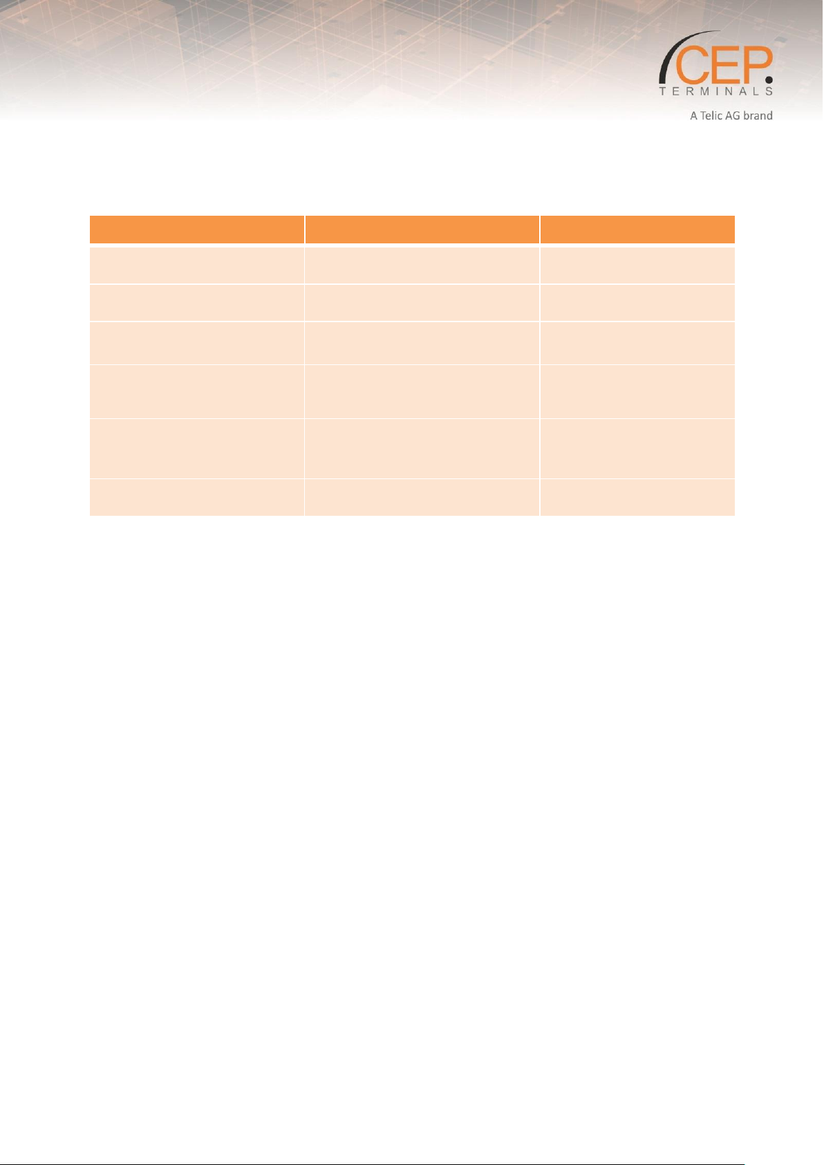
Problem
Possible Reason
Solution
Power LED (L1) stays switched
off
No supply voltage-
Connect power supply
GSM LED (L2) blinks three times
cyclically
PIN is not “0000” or “2468”
Change SIM card’s PIN to
“0000” or “2468”
GSM LED (L2) constantly on
No GSM network available / no
antenna connected
Connect antenna / Change
antenna position
STD3X does not react on
configuration call (not accepting
the call)
Device is already configured
Set back to factory settings
or set new administration
number
STD3X does not react to an
SMS, or call, although booked to
the network
The mobile phone does not
transmit the phone number
(“Incognito”)
Activate the transmission of
the phone number in your
mobile phone
System LEDs toggle
No configuration call received by
STD3X
Make configuration call
6 FAQ and Troubleshooting
6.1 Some troubleshooting hints
Table 9: Troubleshooting
6.2 FAQs
6.2.1 How do I know the version of my STD32/35 V4 and STD32/35 V5
Please check the version of your product using the serial number / IMEI, which is printed on the rear
panel.
The serial number is in each case followed by the IMEI (International Mobile Equipment Identity) of the
device using a four-digit product ID.
Example:
The <IMEI> apply from 0834 for the STD32 V5 to <IMEI> 0833 and the STD32 V4 devices.
The <IMEI> apply from 0824 for the STD35 V5 to <IMEI> 0823 and the STD3X V4 devices.
6.2.2 Can a camera be connected to the STD3X?
No, the STD3X does not support a camera function.
6.2.3 Set or change Master ID?
xxxx are the last 4 Numbers of the serial number/IMEI which is printed on the backside of the device
for example: IMEI=123456789012345 so the Numbers 2345 are the password of the device.
Enter the Master ID Phone: xxxx M1: +49123456789.
To change the Master ID on a new phone number, you use the same commando: xxxx M1:
+49123456789.
But you can also set the Master Phone otherwise.
28
Page 29
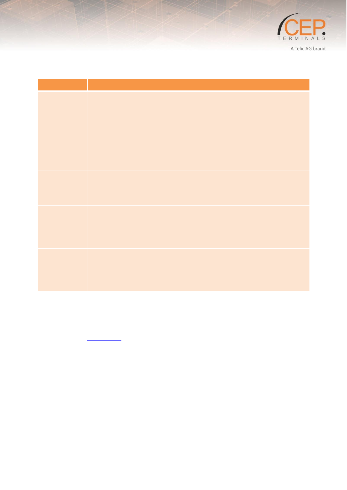
Test steps
Description
Expected result
1.
Connection of the battery and
the external power supply
with the Device
When the Module is booked into
the network the status LED´s
red/green are blinking and the GSM
LED starts blinking yellow in a 2
second Time period.
2.
Call the device with the test
mobile phone
The call will be automatically
accepted and you hear 4 short
sounds. After the sounds the call
will be automatically cancelled
3.
Disconnect and reconnect of
VCC
You will receive a SMS with the
content: “START-UP ALARM”. Your
test mobile phone is now the admin
phone
4.
Connection of the trace
cable(USB cable) with the
device
The traces will start and the number
of the test mobile phone will be
appear. On C:MAIN
[POHONE_NO_MASTER<s>=<01516
1713220>]
5.
Call the Device again with
your test mobile phone
The call will be declined from te
device and the relay 1 will be
switched on for 1 second(The relay
LED will light up)The default
configuration was successfully.
6.2.4 Set Master ID via Phone Call
Now the basic configuration is done which means that all future events will be sent to the Master
Phone and that Relay 1 can be switched from that mobile phone.
To use the additional functions of the STD3X please continue reading the Configuration Manual.
Free Download at: www.telic.de
6.2.5 Clip-List - Add and delete phone number
Add a new phone number to the Clip-List: xxxx CL:+49123456789.
Delete an existing phone number from the Clip-List: xxxx CD:+49123456789.
Add several phone numbers in one command: xxxx CL:+49123456789";"CL:+49123456789.
(max. 160 Symbols)
Attention:
If you enter following command to the expanded clip list CL:*.. Then its possible for everyone to switch
relay 1.
29
Page 30

You can add up to 1000 mobile phone numbers at a STD3x V4.
You can add up to 194 mobile phone numbers at a STD3x V5.
6.2.6 Usage of the SIM card and general preparation
What must be considered by using the SIM card:
We recommend that all devices have a valid and activated standard SIM card of any GSM network
provider (GSM 850/900/1800 or 1900 MHz).
When using pre-paid cards must be ensured that the balance always is sufficient to send a message in
the event of an alarm.
We recommend for all devices a standard [1.8V / 3V] SIM Cards.
You can also use an adapter for Nano and Micro SIM cards.
Attention:
The PIN of this card has to be set to "0000" (4 times zero). As an alternative, you could use the PIN
"2468". To change the PIN you can use a regular mobile phone. Please refer to your mobile phone
manufacture's user manual for instruction on how to change the PIN.
If you use a SIM card with a PIN different from "0000" or "2468" in the STD3X, the device will use a
"wrong" PIN. After the second attempt to power up the device your SIM card will b e blocked. In this
case you need to use the "Super-PIN" or "PUK" to assign new PIN to your card. Please look into the user
guide of your mobile phone. There you find how to use the PUK to un-block the SIM card.
You can also use a SIM card without a configured PIN. In this case the "incognito" or "private call"
function of the mobile must be deactivated in order to be able to administer the STD3X device. In other
words, the ,aster mobile has to transmit the mobile phone number with every call. Please refer to the
user guide of your mobile phone to change this settings.
(To test the settings you can call a different mobile phone there your phone number or name should be
displayed.
6.2.7 What are the differences between STD32 & STD35?
STD3x V4
STD32 V4 has 2 In- and Outputs
STD35 V4 has 5 In- and Outputs where 3 of them are Digital and 2 are analog
STD35 V4 has an integrated Battery to compensate Power failure
STD3x V4 has a Clip list storage place of 1000
STD3x V4 has an integrated Motion sensor
STD3x V5
STD32 V5 has 2 In- and Outputs
STD35 V5 has 5 In- and Outputs where 3 of them are Digital and 2 are analog
STD35 V5 has an integrated Battery to compensate Power failure
STD3x V5 has a Clip list storage place of 194
STD3x V5 has no integrated motion sensor
30
Page 31

6.2.8 Which temperature sensor I can connect to the analogue inputs of the STD3X?
There are no firm recommendations, because the application scenarios are varied and differ from each
other. The following specifications must be observed:
The output voltage of the sensor must be in the range 0-32V.
The analog inputs of the STD3X have a resolution of 12 bit.
6.2.9 Which Software is installed on my STD Device?
To ask for the Software Version please send following command: xxxx VERSION?.
6.2.10 The device doesn't send any SMS, but it is accessible on the mobile network
Please check if you still have available budget if you are using a prepaid SIM card. For example you can
do this by inserting a SIM card in your mobile phone and trying to send an SMS or to make a call.
Check your SMS functionality with your mobile network provider.
6.2.11 Sending E-Mails doesn't work
Please check whether the APN Settings are configured correctly. You can find the APN settings e.g. on
the homepage of your mobile mobile network provider.
By default our SMTP Server is preset. We advise you to use it.
Please contact our Support Team if you have configured a different SMTP Server and you want to use
our standard server.
6.2.12 Why does my device have no GSM reception?
Please check the following items:
Is the antenna correctly screwed onto the device?
Is the SIM card inserted in the device?
Check the SMS & Voice Call functionality with your mobile provider
Is a GSM network available at the device's location?
31
 Loading...