

Telic SBC-AVL Power, SBC-AVL User Manual
dfdfdsf
1
SBC-AVL
User Manual Version 2.4
SBC-AVL / SBC-AVL Power

dfdfdsf
2
Table of Contents
1 Overview _________________________________________________________________________ 5
2 Applicable Products ________________________________________________________________ 5
3 Delivery Content ___________________________________________________________________ 6
4 SBC-AVL Components _______________________________________________________________ 7
5 Operating Set up ___________________________________________________________________ 8
5.1 Operating the device ___________________________________________________________________ 8
5.2 Insert the SIM Card_____________________________________________________________________ 8
5.3 Close the cover _______________________________________________________________________ 10
5.4 Powering up the device ________________________________________________________________ 10
5.4.1 Wiring description ____________________________________________________________________________ 11
5.5 LED behavior_________________________________________________________________________ 12
6 Troubleshooting hints ______________________________________________________________ 13
6.1 The device cannot connect to a GSM network ______________________________________________ 13
6.2 The device doesn’t log into the GPRS network ______________________________________________ 13
6.3 The device doesn’t receive GPS data ______________________________________________________ 14
7 Basic features ____________________________________________________________________ 15
7.1 Event Types _________________________________________________________________________ 15
7.2 Connection Establishment Procedure _____________________________________________________ 15
7.3 Event Message Structure _______________________________________________________________ 15
8 Advanced Features ________________________________________________________________ 17
8.1 Geofencing __________________________________________________________________________ 17
8.2 Roaming alternative configuration _______________________________________________________ 17
8.3 Input alternative configuration __________________________________________________________ 17
8.4 Device Watchdogs ____________________________________________________________________ 17
8.5 GSM Jamming detection feature _________________________________________________________ 18
8.6 Glonass enabling _____________________________________________________________________ 18
8.7 1-Wire ______________________________________________________________________________ 18
8.8 CAN Bus (Only for SBC–AVL) ____________________________________________________________ 18
8.9 RS232 (Only for SBC–AVL Power) _________________________________________________________ 18
8.10 Additional Features ___________________________________________________________________ 18
9 Connect to the vehicle _____________________________________________________________ 19
9.1 Placing the device into the vehicle ________________________________________________________ 19
9.2 Wiring connection ____________________________________________________________________ 19
10 Safety __________________________________________________________________________ 20

dfdfdsf
3
10.1 General Battery handling _______________________________________________________________ 20
10.2 Battery storage _______________________________________________________________________ 20
10.3 Battery disposal ______________________________________________________________________ 21
11 General Terms and Conditions _______________________________________________________ 22
12 Documentation change LOG_________________________________________________________ 23

dfdfdsf
4
Table Overview
Table 1: The different versions of the SBC-AVL ................................................................................................ 5
Table 2: Accessories .......................................................................................................................................... 6
Table 3: Components of SBC-AVL and SBC-AVL Power .................................................................................... 7
Table 4: SBC-AVL Cable Color description ...................................................................................................... 11
Table 5: LED Behaviour ................................................................................................................................... 12
Table 6: The device cannot connect to a GSM network................................................................................. 13
Table 7: The device doesn’t log into the GPRS network ................................................................................ 13
Table 8: The device doesn’t receive GPS data ................................................................................................ 14
Table 9: Content description .......................................................................................................................... 16
Table 10: Documentation change LOG ........................................................................................................... 23
Figure Overview
Figure 1: The button to open the SBC-AVL Housing ......................................................................................... 8
Figure 2: How to open the SBC-AVL Housing ................................................................................................... 8
Figure 3: How to insert the SIM Card ............................................................................................................... 9
Figure 4: Where to insert the SIM Card ............................................................................................................ 9
Figure 5: How to close the SBC- AVL Housing ................................................................................................ 10
Figure 6: SBC-AVL Cable Pin allocation ........................................................................................................... 11
Figure 7: SBC-AVL Connector .......................................................................................................................... 11
Figure 8: Geofencing ....................................................................................................................................... 17
dfdfdsf
5
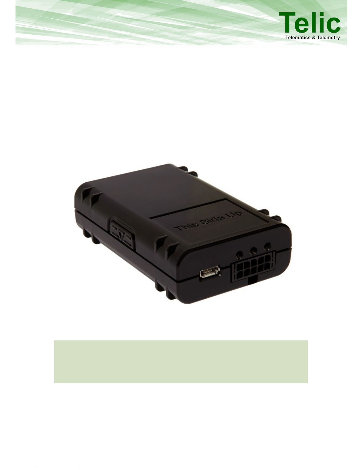
1 Overview
The SBC-AVL family of products from Telic is an innovative telematics unit offering a wide range of
tracking and monitoring configuration options.
The extremely small form factor combined with high quality performance enables the user to deploy
the SBC-AVL in a variety of applications. The SBC-AVL is designed for deployment in passenger cars,
any type of commercial vehicles, fleets of taxis, rental cars or in public transportation vehicles.
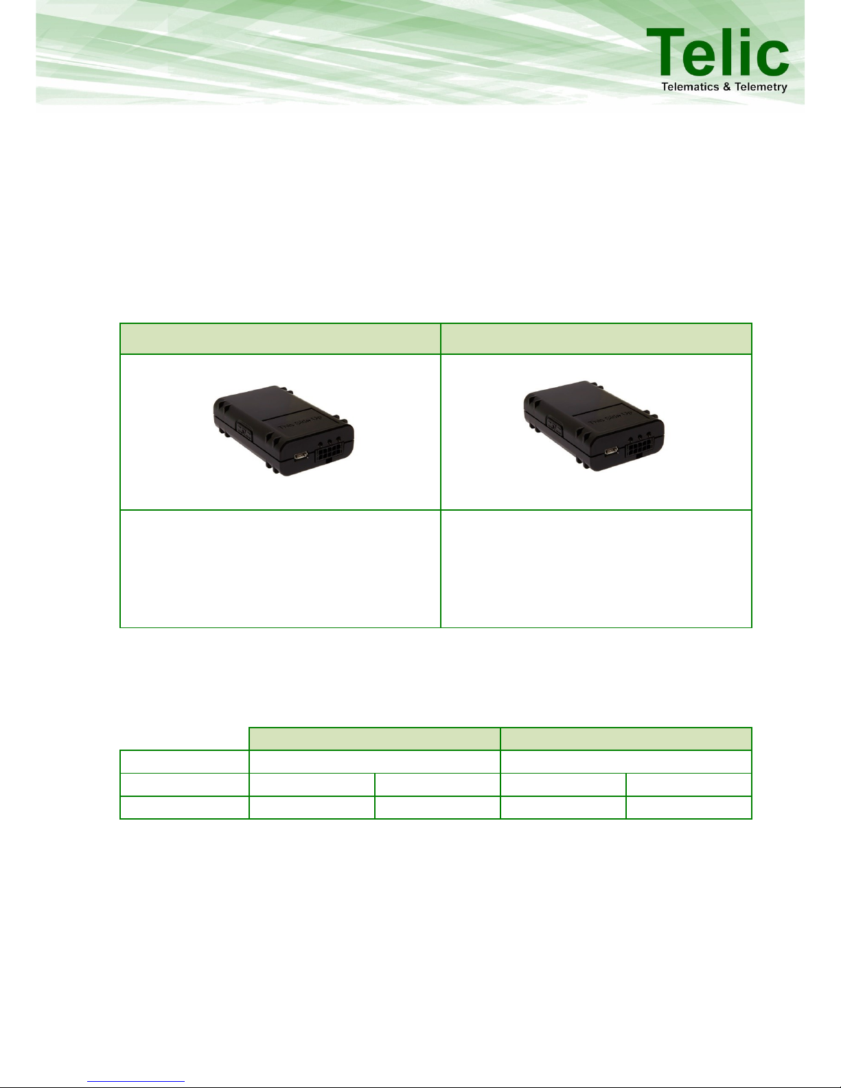
The SBC-AVL is available in the following two variants:
SBC-AVL
SBC-AVL Power
Ideal for advanced track and tracing
applications. In addition to general purpose
inputs and outputs, SBC-AVL supports also 1wire and CAN bus interfaces.
Ideal for advanced track and tracing
applications, where also security features are
required, such as a backup battery or GSM
jamming. In addition to general purpose I/Os,
SBC-AVL Power supports also 1-wire and serial
interfaces based on LVTTL.
Table 1: The different versions of the SBC-AVL
2 Applicable Products
This user manual is applicable for the following products:
SBC-AVL
SBC-AVL Power
Part Number
04000
04001
HW Revision
D3f
D4i
D3g
D4j
Serial No.
0404<IMEI>
0406<IMEI>
0405<IMEI>
0407<IMEI>
dfdfdsf
6
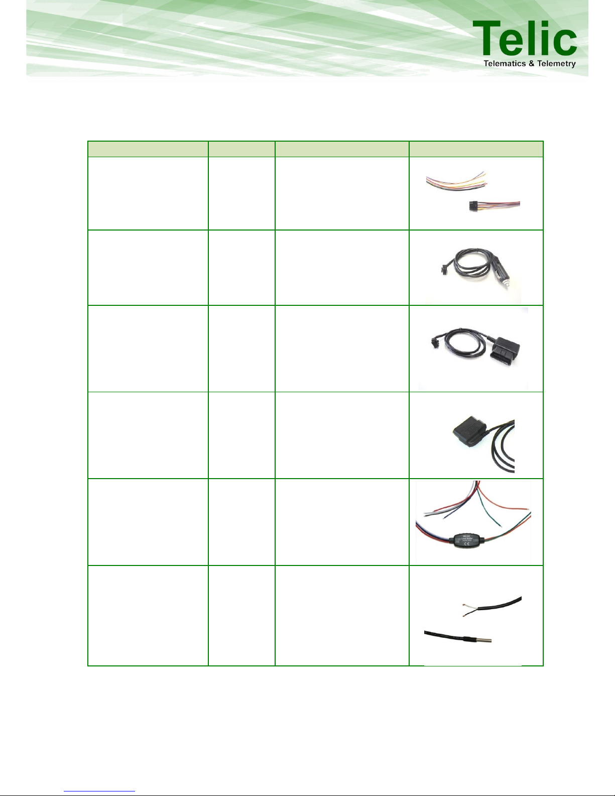
3 Delivery Content
In addition to the SBC-AVL, the following accessories can be part of the shipment, if previously
ordered.
Accessory Name
Order code
Functionality
Picture
Connection cable SBC AVL
16032
Automotive molex cable for
on vehicle installation
Cigarette lighter charger
SBC-AVL
17024
Charger cable for
connecting the device to
the Cigarette lighter
OBD II Power Supply
Cable
17023
2-pin OBD-II connector
cable for power supply
only;
Cable length: 1 m
OBD II CAN Cable
17027
4-pin OBD-II
connector/cable for power
supply + CAN High/Low;
Cable length: 1 m
RS232 Level Shifter
16105
Level shifter from LV-TTL
(3.3V) to RS232 (12V);
Open Wires (VCC; GND;
RS232 Rx &Tx; TTL Rx & Tx);
Cable length: 1 m
1-wire Temperature
Sensor
90029
1-wire Temperature sensor;
Cable length: 7 m;
Temperature range: -55 °C
to +125 °C;
Accuracy: ± 0,5°C (in range -
10 °C to +85 °C)
Table 2: Accessories
dfdfdsf
7
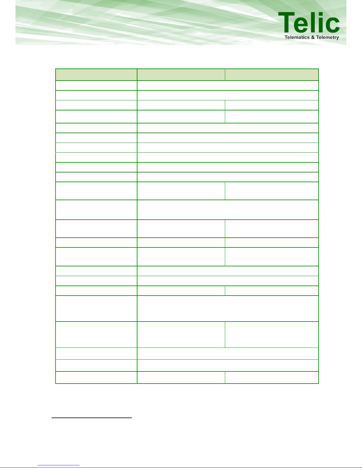
4 SBC-AVL Components
Feature
SBC-AVL
SBC-AVL Power
Certifications
E1, FCC1
GSM/GPRS
Quad Band
Receiver Type
56-channel GPS engine
56-channel GPS engine
GSM Jamming Detection
Yes
Yes
Housing
Small & Compact Design
Antenna Connector
Internal
Interface Connector
10-pin Molex
Status Indicators
3 LEDs (GSM; GPS; Battery)
Ignition Status (On/Off)
1x
General Purpose Inputs
1x
Digital Outputs
1x (300 mA max; low side
switch) 2
2x (300 mA max; low side
switch) 3
1-Wire
iButton ID key
Temperature Sensor (DS18S20; DS18B20; DS1921G)
CAN Bus
Configurable CAN; OBD-II;
FMS
--
RS232 / UART
--
1x (LVTTL; 3.3V)
USB
Configure & Trace
Configure & Trace
Battery charging
Message Storage Capacity
~ 20000 (location data only)
External voltage range
7V - 32V
Battery Capacity
--
660 mAh (LiPo)
Typical consumption in
sleep Mode (@12V) external source
≤ 0,5 mA
Typical consumption in
sleep Mode (internal
battery)
≤ 0,08 mA
Dimensions
74x49x20 mm
Operating temperature
-30°C to +75°C
Recharging temperature
N/A
0°C to +45°C
Table 3: Components of SBC-AVL and SBC-AVL Power
1
This device complies with Part 15 of the FCC Rules. Operation is subject to the following two conditions: (1) this device may not cause
harmful interference; (2) this device must accept any interference received, including interference that may cause undesired
operation.
2
Applicable from hardware with serial numbers 0406<IMEI> or higher.
3
Applicable from hardware with serial numbers 0407<IMEI> or higher. Earlier hardware versions support 1x digital output.
 Loading...