

Page 1
dfdfdsf
1
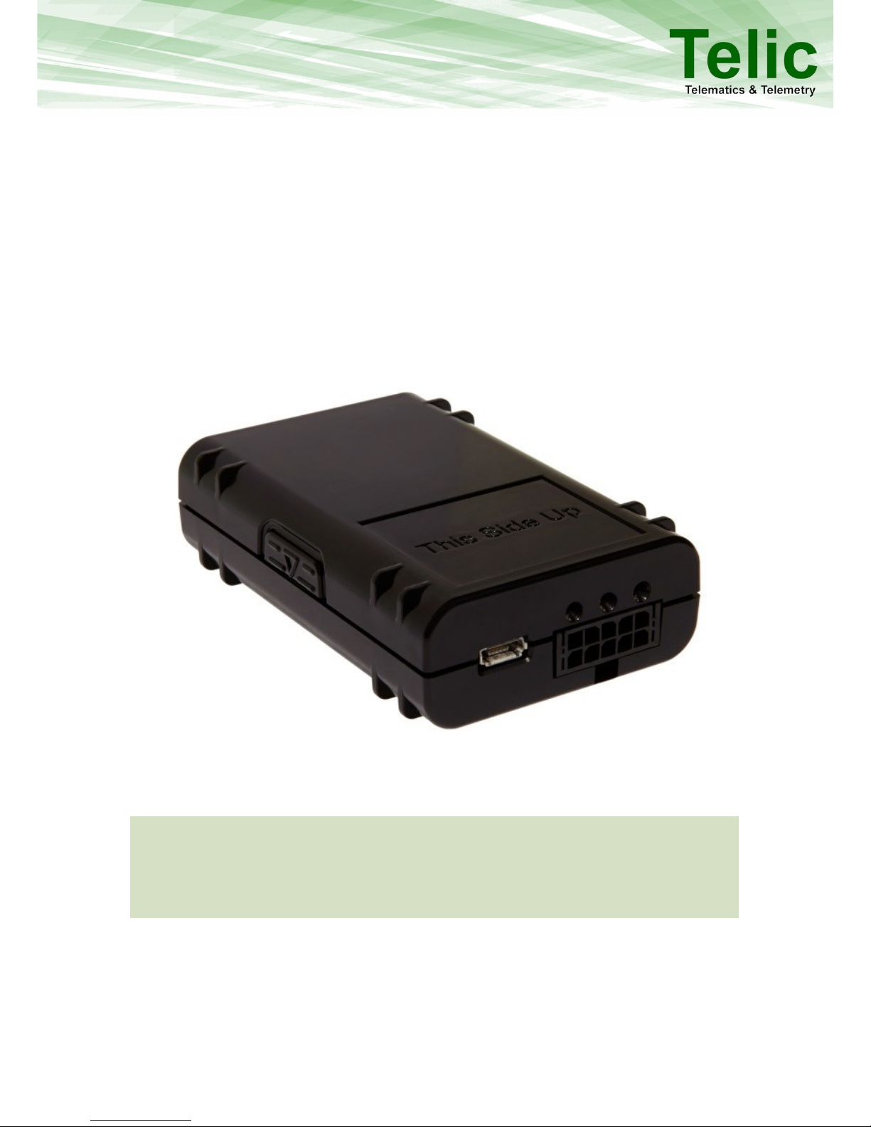
SBC-AVL
User Manual Version 2.4
SBC-AVL / SBC-AVL Power
Page 2

dfdfdsf
2
Table of Contents
1 Overview _________________________________________________________________________ 5
2 Applicable Products ________________________________________________________________ 5
3 Delivery Content ___________________________________________________________________ 6
4 SBC-AVL Components _______________________________________________________________ 7
5 Operating Set up ___________________________________________________________________ 8
5.1 Operating the device ___________________________________________________________________ 8
5.2 Insert the SIM Card_____________________________________________________________________ 8
5.3 Close the cover _______________________________________________________________________ 10
5.4 Powering up the device ________________________________________________________________ 10
5.4.1 Wiring description ____________________________________________________________________________ 11
5.5 LED behavior_________________________________________________________________________ 12
6 Troubleshooting hints ______________________________________________________________ 13
6.1 The device cannot connect to a GSM network ______________________________________________ 13
6.2 The device doesn’t log into the GPRS network ______________________________________________ 13
6.3 The device doesn’t receive GPS data ______________________________________________________ 14
7 Basic features ____________________________________________________________________ 15
7.1 Event Types _________________________________________________________________________ 15
7.2 Connection Establishment Procedure _____________________________________________________ 15
7.3 Event Message Structure _______________________________________________________________ 15
8 Advanced Features ________________________________________________________________ 17
8.1 Geofencing __________________________________________________________________________ 17
8.2 Roaming alternative configuration _______________________________________________________ 17
8.3 Input alternative configuration __________________________________________________________ 17
8.4 Device Watchdogs ____________________________________________________________________ 17
8.5 GSM Jamming detection feature _________________________________________________________ 18
8.6 Glonass enabling _____________________________________________________________________ 18
8.7 1-Wire ______________________________________________________________________________ 18
8.8 CAN Bus (Only for SBC–AVL) ____________________________________________________________ 18
8.9 RS232 (Only for SBC–AVL Power) _________________________________________________________ 18
8.10 Additional Features ___________________________________________________________________ 18
9 Connect to the vehicle _____________________________________________________________ 19
9.1 Placing the device into the vehicle ________________________________________________________ 19
9.2 Wiring connection ____________________________________________________________________ 19
10 Safety __________________________________________________________________________ 20
Page 3

dfdfdsf
3
10.1 General Battery handling _______________________________________________________________ 20
10.2 Battery storage _______________________________________________________________________ 20
10.3 Battery disposal ______________________________________________________________________ 21
11 General Terms and Conditions _______________________________________________________ 22
12 Documentation change LOG_________________________________________________________ 23
Page 4

dfdfdsf
4
Table Overview
Table 1: The different versions of the SBC-AVL ................................................................................................ 5
Table 2: Accessories .......................................................................................................................................... 6
Table 3: Components of SBC-AVL and SBC-AVL Power .................................................................................... 7
Table 4: SBC-AVL Cable Color description ...................................................................................................... 11
Table 5: LED Behaviour ................................................................................................................................... 12
Table 6: The device cannot connect to a GSM network................................................................................. 13
Table 7: The device doesn’t log into the GPRS network ................................................................................ 13
Table 8: The device doesn’t receive GPS data ................................................................................................ 14
Table 9: Content description .......................................................................................................................... 16
Table 10: Documentation change LOG ........................................................................................................... 23
Figure Overview
Figure 1: The button to open the SBC-AVL Housing ......................................................................................... 8
Figure 2: How to open the SBC-AVL Housing ................................................................................................... 8
Figure 3: How to insert the SIM Card ............................................................................................................... 9
Figure 4: Where to insert the SIM Card ............................................................................................................ 9
Figure 5: How to close the SBC- AVL Housing ................................................................................................ 10
Figure 6: SBC-AVL Cable Pin allocation ........................................................................................................... 11
Figure 7: SBC-AVL Connector .......................................................................................................................... 11
Figure 8: Geofencing ....................................................................................................................................... 17
Page 5
dfdfdsf
5
1 Overview
The SBC-AVL family of products from Telic is an innovative telematics unit offering a wide range of
tracking and monitoring configuration options.
The extremely small form factor combined with high quality performance enables the user to deploy
the SBC-AVL in a variety of applications. The SBC-AVL is designed for deployment in passenger cars,
any type of commercial vehicles, fleets of taxis, rental cars or in public transportation vehicles.
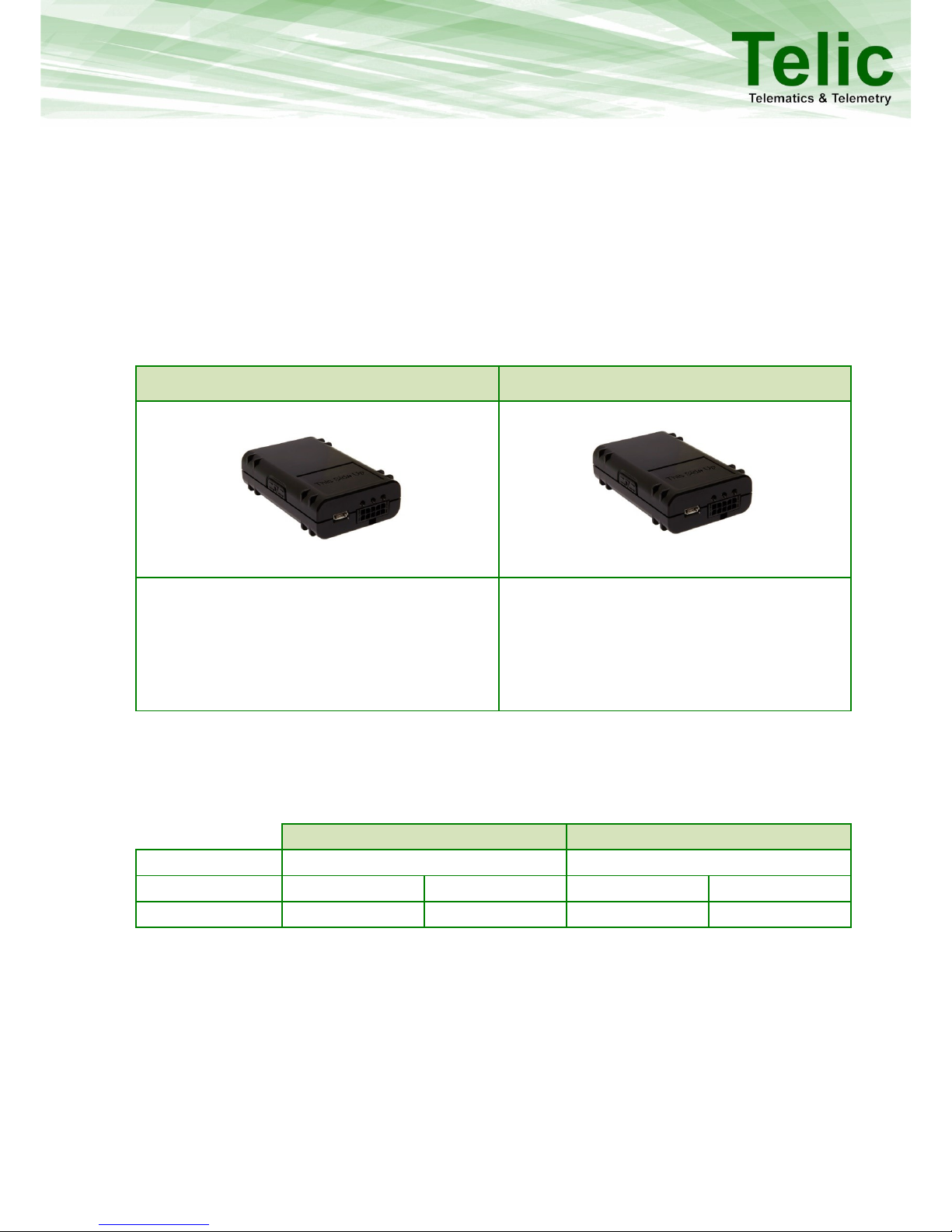
The SBC-AVL is available in the following two variants:
SBC-AVL
SBC-AVL Power
Ideal for advanced track and tracing
applications. In addition to general purpose
inputs and outputs, SBC-AVL supports also 1wire and CAN bus interfaces.
Ideal for advanced track and tracing
applications, where also security features are
required, such as a backup battery or GSM
jamming. In addition to general purpose I/Os,
SBC-AVL Power supports also 1-wire and serial
interfaces based on LVTTL.
Table 1: The different versions of the SBC-AVL
2 Applicable Products
This user manual is applicable for the following products:
SBC-AVL
SBC-AVL Power
Part Number
04000
04001
HW Revision
D3f
D4i
D3g
D4j
Serial No.
0404<IMEI>
0406<IMEI>
0405<IMEI>
0407<IMEI>
Page 6
dfdfdsf
6
3 Delivery Content
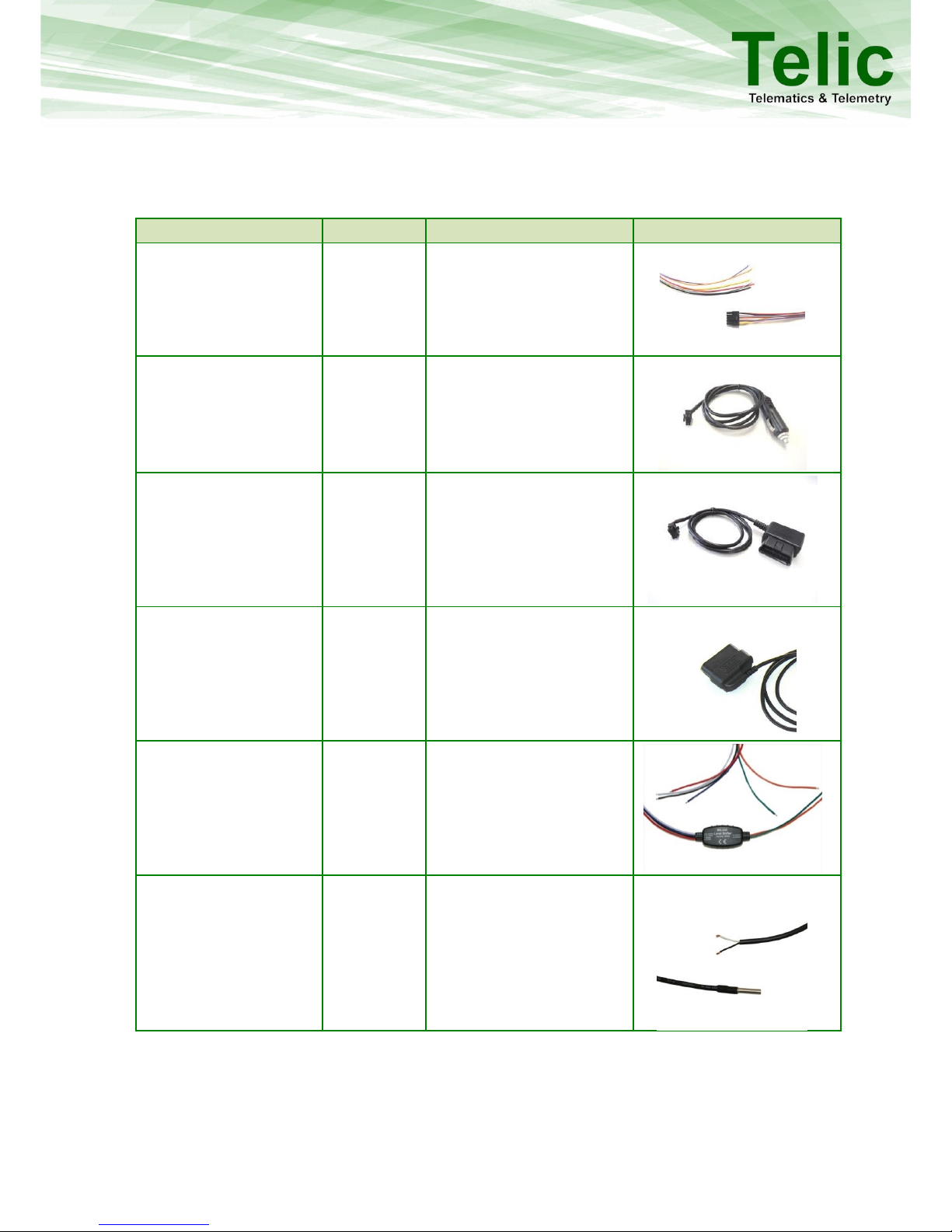
In addition to the SBC-AVL, the following accessories can be part of the shipment, if previously
ordered.
Accessory Name
Order code
Functionality
Picture
Connection cable SBC AVL
16032
Automotive molex cable for
on vehicle installation
Cigarette lighter charger
SBC-AVL
17024
Charger cable for
connecting the device to
the Cigarette lighter
OBD II Power Supply
Cable
17023
2-pin OBD-II connector
cable for power supply
only;
Cable length: 1 m
OBD II CAN Cable
17027
4-pin OBD-II
connector/cable for power
supply + CAN High/Low;
Cable length: 1 m
RS232 Level Shifter
16105
Level shifter from LV-TTL
(3.3V) to RS232 (12V);
Open Wires (VCC; GND;
RS232 Rx &Tx; TTL Rx & Tx);
Cable length: 1 m
1-wire Temperature
Sensor
90029
1-wire Temperature sensor;
Cable length: 7 m;
Temperature range: -55 °C
to +125 °C;
Accuracy: ± 0,5°C (in range -
10 °C to +85 °C)
Table 2: Accessories
Page 7
dfdfdsf
7
4 SBC-AVL Components
Feature
SBC-AVL
SBC-AVL Power
Certifications
E1, FCC1
GSM/GPRS
Quad Band
Receiver Type
56-channel GPS engine
56-channel GPS engine
GSM Jamming Detection
Yes
Yes
Housing
Small & Compact Design
Antenna Connector
Internal
Interface Connector
10-pin Molex
Status Indicators
3 LEDs (GSM; GPS; Battery)
Ignition Status (On/Off)
1x
General Purpose Inputs
1x
Digital Outputs
1x (300 mA max; low side
switch) 2
2x (300 mA max; low side
switch) 3
1-Wire
iButton ID key
Temperature Sensor (DS18S20; DS18B20; DS1921G)
CAN Bus
Configurable CAN; OBD-II;
FMS
--
RS232 / UART
--
1x (LVTTL; 3.3V)
USB
Configure & Trace
Configure & Trace
Battery charging
Message Storage Capacity
~ 20000 (location data only)
External voltage range
7V - 32V
Battery Capacity
--
660 mAh (LiPo)
Typical consumption in
sleep Mode (@12V) external source
≤ 0,5 mA
Typical consumption in
sleep Mode (internal
battery)
≤ 0,08 mA
Dimensions
74x49x20 mm
Operating temperature
-30°C to +75°C
Recharging temperature
N/A
0°C to +45°C
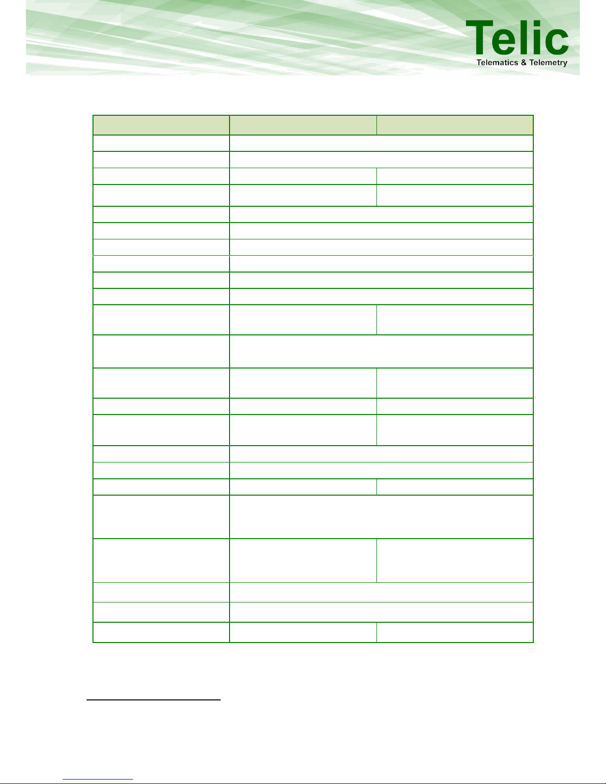
Table 3: Components of SBC-AVL and SBC-AVL Power
1
This device complies with Part 15 of the FCC Rules. Operation is subject to the following two conditions: (1) this device may not cause
harmful interference; (2) this device must accept any interference received, including interference that may cause undesired
operation.
2
Applicable from hardware with serial numbers 0406<IMEI> or higher.
3
Applicable from hardware with serial numbers 0407<IMEI> or higher. Earlier hardware versions support 1x digital output.
Page 8
dfdfdsf
8
5 Operating Set up
The operation set-up of the tracking and tracing module can be realised in few quick steps.
Please take proper ESD protection measures (e.g. electrical connection of the
body to ground) to make sure you don’t destroy internal electronics! Repair of
ESD damages caused by user’s negligence will not be covered by Telic’s
warranty. Electrostatic discharge (ESD) is the sudden and momentary electric
current that flows between two objects at different electrical potentials
normally caused by static electricity.
5.1 Operating the device
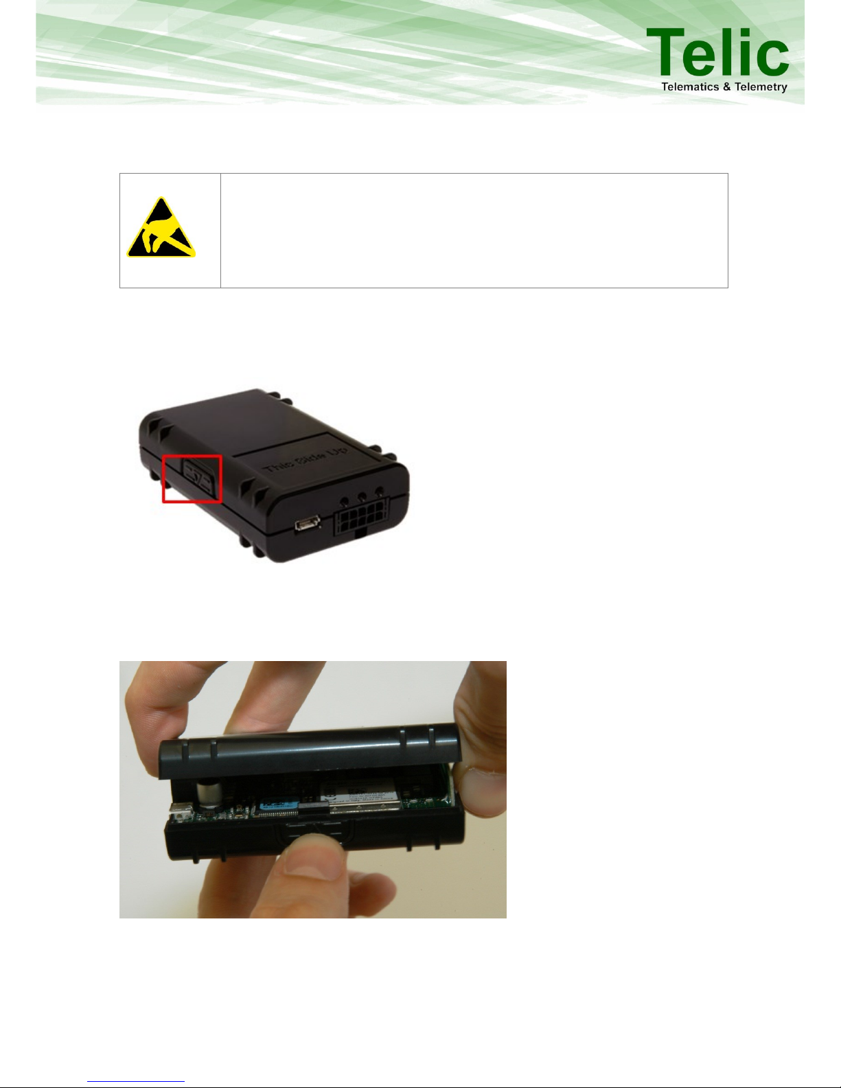
Please open the SBC-AVL housing by pushing the button shown here:
Figure 1: The button to open the SBC-AVL Housing
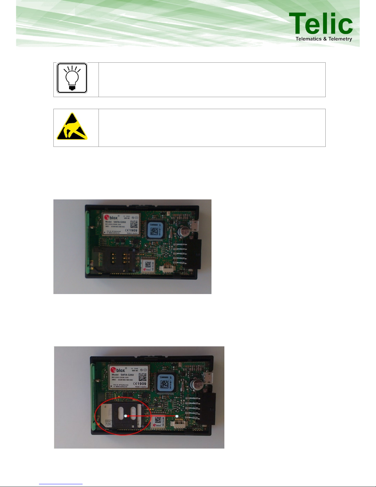
While keeping the button pushed remove the top cover with the other hand as shown. The SIM card
holder can be found under the top cover.
Figure 2: How to open the SBC-AVL Housing
5.2 Insert the SIM Card
A working SIM card from a suitable network provider must be properly inserted in order for the
device to operate correctly.
Page 9
dfdfdsf
9
If the SIM card is not PIN free, it has to be ensured that the PIN is set to
“0000”. To speed up the log-in process into the GSM network, the SIM card
should contain no or only a few phone book entries.
The messages of the SBC-AVL are transmitted via the mobile GSM network.
Therefore you need a standard 3 Volts or 1.8 Volts SIM card. Please give
preference to post-paid SIM cards!
The insertion of the SIM card into the SBC-AVL is easy:
Place the device in front of you on the desk such showed in the picture.
Slide the SIM card cover carefully on left.
Figure 3: How to insert the SIM Card
Carefully flip the card reader sideways then up. Now insert the SIM card into the SIM card holder
so that the cut corner matches with the corresponding marking on the SIM card holder. Do not
touch the contacts of the SIM card. If necessary clean the contacts with a soft cloth.
Figure 4: Where to insert the SIM Card
Page 10
dfdfdsf
10
When inserted correctly the gold contacts of the SIM card should be facing down.
Flip the SIM card holder back into its original position and slide the lock back on right till it is
locked
If you cannot close the SIM card holder, you may have inserted the SIM card in the wrong
direction
With this step you have finished the SIM card installation
5.3 Close the cover
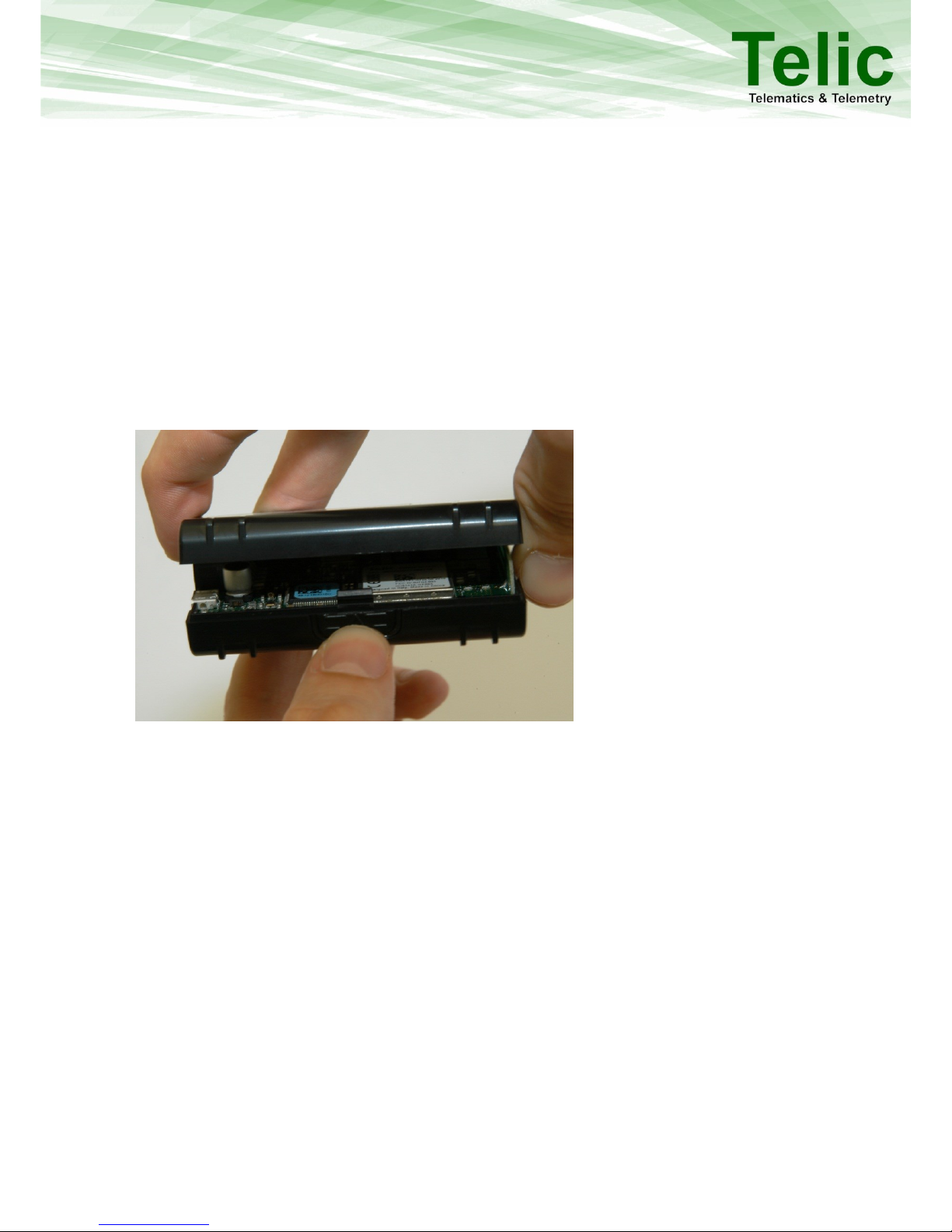
Please close the SBC-AVL housing by pushing the top cover against the down side until there is nomore space between the 2 surfaces.
Figure 5: How to close the SBC- AVL Housing
5.4 Powering up the device
The SBC-AVL needs to be connected to a power source (7 – 32 volt direct current). It can be powered
by a car battery, a rechargeable battery or a stabilized DC power supply. The USB connector is
available only for tracing and configuration functionalities; in case of the SBC-AVL Power, it can also
be used to charge the internal battery. If the SBC-AVL is connected only to the USB port, without VCC
and GND the GPS and GSM modules will remain switched off, even when the device is connected to
the USB port, it will not go into any kind of sleep mode. The SBC-AVL Power version else is able to
power up GPS and GSM modules also while just connected to the USB port, without main power.
Page 11
dfdfdsf
11
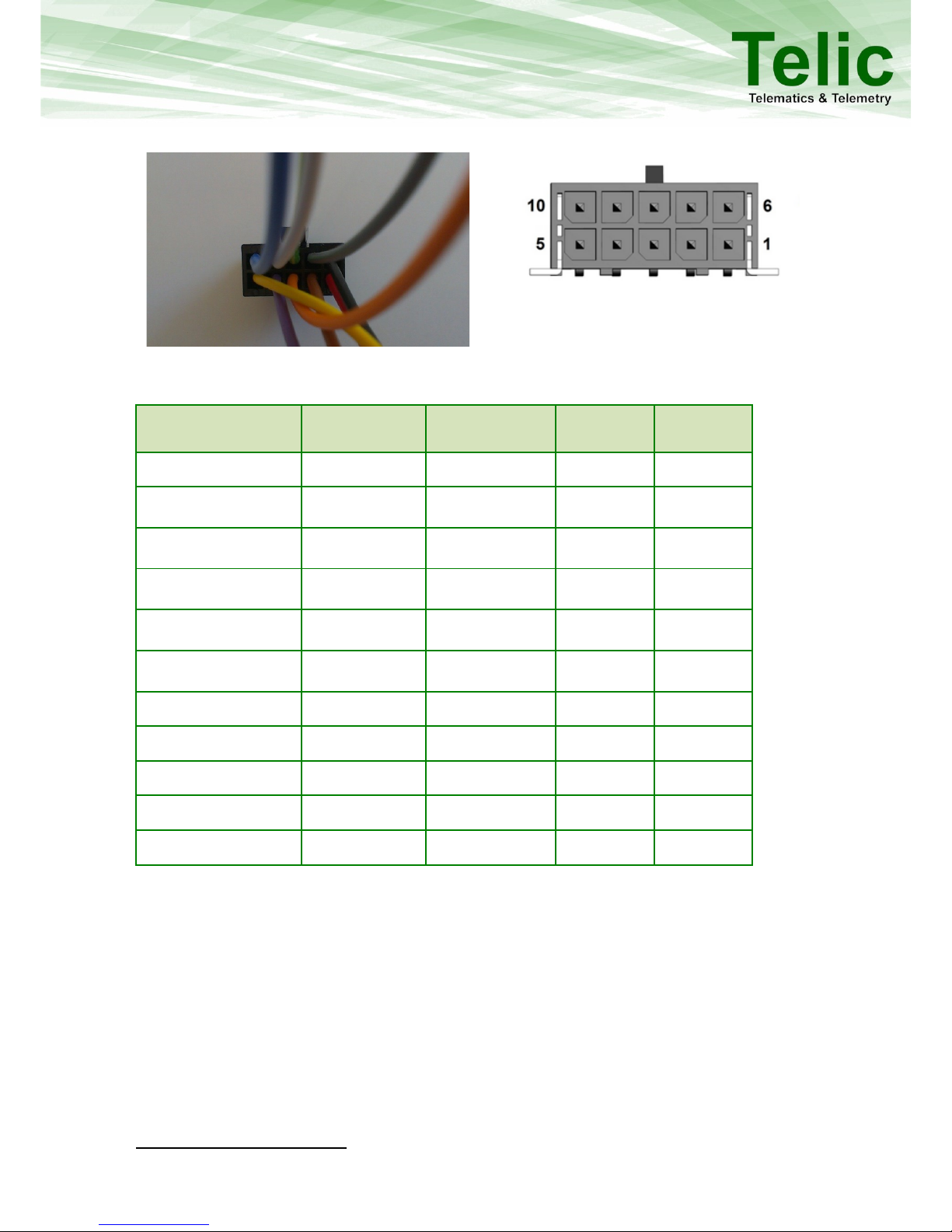
5.4.1 Wiring description
Signal
Cable Color
Connection
SBC-AVL
SBC-AVL
Power
VCC /IN 3
Red (pin 1)
Required
X
X
GND
Black (pin 6)
Required
X
X
IGNITION INPUT (1)
Yellow (pin 5)
Recommended
X
X
DIG_IN 2 (ANA_IN1)
Violet (pin 4)
Optional
X
X
1-wire
Grey (pin 7)
Optional
X
X
DIG_OUT1
Orange (pin3)
Optional
X 4
X
DIG_OUT2
Brown(pin2)
Optional
X 5
CAN-H
Brown(pin2)
Optional
X
CAN-L
Green (pin 8)
Optional
X
RS232 LVTTL RX
White (pin 9)
Optional
X
RS232 LVTTL TX
Blue (pin 10)
Optional
X
Table 4: SBC-AVL Cable Color description
4
Applicable from hardware with serial numbers 0406<IMEI> or higher.
5
Applicable from hardware with serial numbers 0407<IMEI> or higher.
Figure 6: SBC-AVL Cable Pin allocation
This side up
Figure 7: SBC-AVL Connector
Page 12
dfdfdsf
12
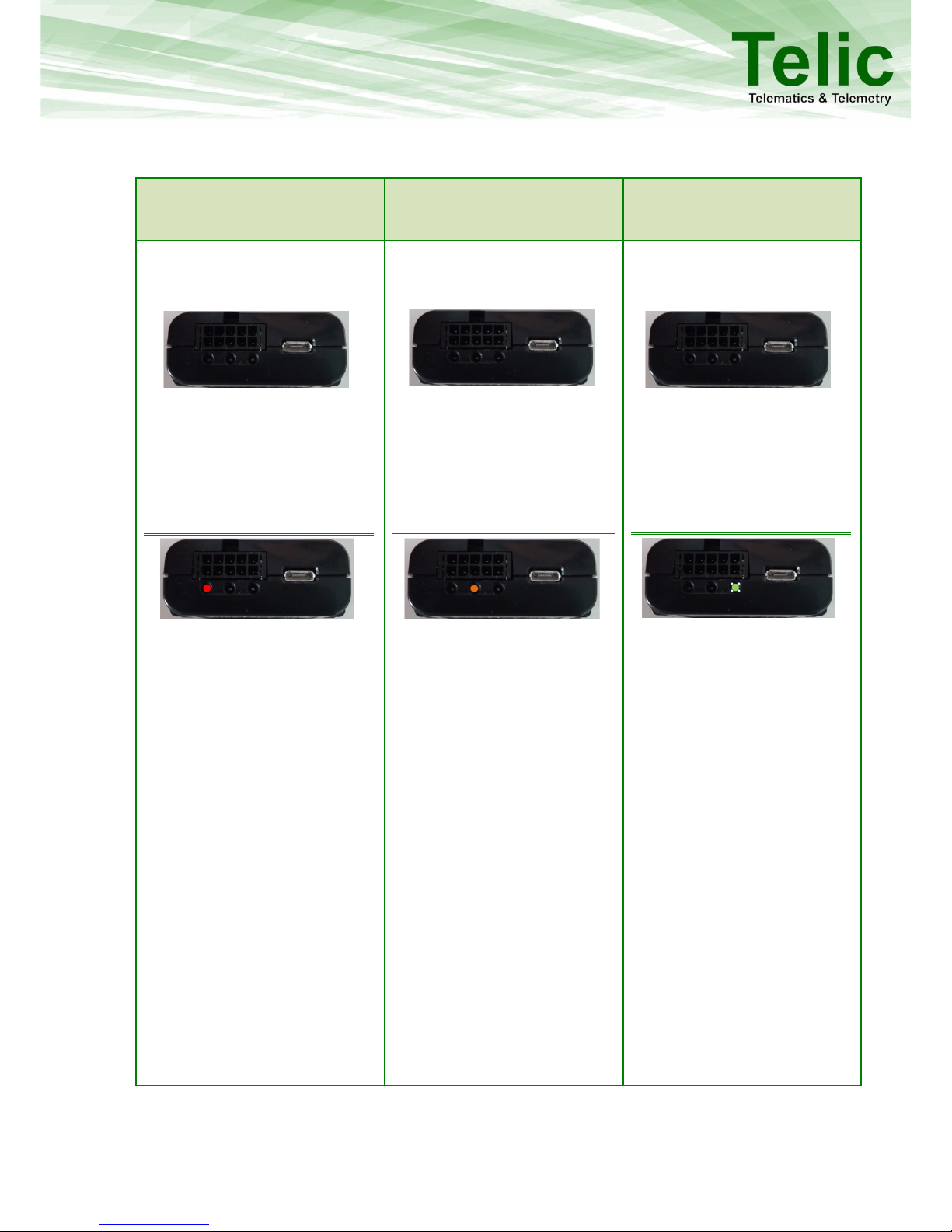
5.5 LED behavior
Left indicator: Power supply
status
Middle Indicator: GSM status
Right Indicator: GPS status
The left indicator consists of a red
one.
SBC AVL: When the LED is off, the
device is not powered.
SBC AVL Power: When the LED is
off, the device is not powered
even in sleep mode.
SBC-AVL:
Blinking once: Device is powered
(7- 32V)
Blinking twice: Powered only via
USB (GSM/ GPS off)
SBC- AVL Power:
Blinking once: Powered (7-32V)
and internal battery fully charged
Blinking twice: Low battery voltage
On: Internal battery charging
The orange LED reflects the GSM
status and also whether the device is
switching on
When the LED is off, the GSM
Module is not active.
Permanently on: GSM is active,
but no GSM networks available /
not yet registered.
Blinking once: Device is logged
into the GSM network, no
connection to server
Blinking twice: Device is logged
into GSM network, GPRS is
attached, established TCP/ IP
connection to server
A very short flash while the device
is in sleep mode means that a
movement has been detected.
This LED blinks green and indicates
the status of the GPS receiver
Off: GPS is not switched on
Blinking once: Position acquisition
Blinking twice: 2D-Fix (no valid
height)
Blinking three times: 3D-Fix (GPS
data is complete)
After start up as well as after a
phase without GPS reception the
device only accepts 3D GPS
positions
This ensures, that 2D positions
reports with serious deviations
from the real position are not
reported to the control center.
After a while, 2D position reports
are accepted because the GPS
receiver then had enough time
to evaluate the signal quality of
all available GPS satellites.
A very short flash every 2
seconds indicates that the device
is in sleep mode
Table 5: LED Behaviour
Page 13

dfdfdsf
13
6 Troubleshooting hints
6.1 The device cannot connect to a GSM network
Possible issue source
Trouble shooting
The unit is not connected correctly to your
vehicle
Please connect the unit to the vehicle according to the
information in this manual
On-board power supply failure or defective
internal fuse
You cannot fix this problem yourself. These fuses should
protect the device and the periphery and only get damaged
by extensive surcharge. You have to send the device to Telic
or to your supplier.
Table 6: The device cannot connect to a GSM network
6.2 The device doesn’t log into the GPRS network
Possible issue source
Troubleshooting
The Telic SBC-AVL isn’t in a GSM covered
area.
Please check whether there is GSM reception in this area
(e.g. using a cell phone) and move eventually to another
area.
The SIM card in the SBC-AVL is new and has
not yet been activated
Please check, whether the SIM card is already activated.
This can be done e.g. by putting the SIM card in your cell
phone and checking whether or not your cell phone is able
to log into a GSM network.
The SIM card has been locked by the
provider.
Please check whether the SIM card is locked.
This can be done e.g. by putting the SIM card into your cell
phone and checking whether your cell phone is able to log
into a GSM network.
Is this not the case, than please try to make a phone call. If
you are successful, the SIM card is definitely not locked.
The prepaid bonus is exhausted.
Please recharge the SIM card placed in the device.
The prepaid SIM card is no longer valid.
Prepaid SIM cards will lose their validity, if they aren’t
reloaded on a regular basis (often after 12 or 24 months).
In this case usually you have to buy a new SIM card.
The PIN code of the card hasn’t been
deactivated
Respectively
The PIN on the SIM card is not
corresponding to “0000”.
Please remove the SIM card from the device and check the PIN
code.
The PIN code has to be deactivated or has to be set to “0000”.
After a triple wrong entry of the PIN, unblocking the SIM card
requires the PUK.
The SIM card hasn’t been inserted into the
SIM card holder in the correct way.
Please check the correct position of the SIM card in the card
holder.
The GPRS service is not yet activated.
Please ask your provider whether the GPRS function is
already activated for the SIM card in use.
Table 7: The device doesn’t log into the GPRS network
Page 14

dfdfdsf
14
6.3 The device doesn’t receive GPS data
Possible issue source
Troubleshooting
The GPS internal antenna has no free sight
to the sky.
Please be aware, that a GPS internal antenna needs always
clear view to the sky. Look for a better installation place of the
device inside the vehicle.
Your vehicle is placed in an unsuitable
place.
Please consider that a GPS reception is only possible in case of
free sight between the GPS receiver and the sky.
Please put your car for the test in a more suitable place (no
buildings nearby, outside of a garage / factory etc.)
Table 8: The device doesn’t receive GPS data
Page 15

dfdfdsf
15
7 Basic features
The device can be configured via serial cable by using the Telic Configuration tool otherwise
remotely via SMS and GPRS. Please contact Telic GmbH to have more details about the configuration
procedure.
7.1 Event Types
The SBC-AVL’s primarily task is to transmit GPS position data, including additional status information
via a TCP/IP connection to the tracking server. If a message can’t be transmitted, it will be stored in
the device to be transmitted later. There is a storage capacity of about 20.000 position messages.
The following events will generate a position message which always contains the GPS position:
Time event: The end of a time period of x seconds (x being configurable).
Distance event: After a distance of x meters (straight line distance to the previous event) in any
direction (x being configurable) has been travelled.
Angular course change event: A direction change of a configurable minimum angle in x degrees (x
being configured) at a configurable minimum speed of y km/h (y being configurable).
7.2 Connection Establishment Procedure
The GSM and GPS modules will power up after switching on the SBC-AVL device. After logging in into
the GSM network the SBC-AVL will attempt to establish a GPRS communication link. Finally a TCP/IP
connection to the tracking server will be established to transmit the event messages.
The selection of the GSM network operator will take about 1 minute, plus the time to build up the
GPRS- and TCP/IP-connections to the tracking server. Therefore, after switching on the device, it will
take approximately 2-3 minutes until the first status message can be transmitted. Independent of
this procedure, GPS positions and status information will be generated and stored in the internal
memory for later transmission. Here follows the message structure.
7.3 Event Message Structure
The first identified and valid GPS position will be taken as the reference position for the distance
interval calculations. The next distance interval event will be generated if the configured distance has
been reached. If another event (e.g. time interval event) has been generated before, the distance
interval measurement starts again at the position of this new event. That means that any position
message with an actual GPS position sets a new reference for the distance interval calculations. This
reduces the number of messages sent while still keeping the desired resolution of the tracking
application.
A position message will also be generated in the case of a direction change being greater than the
configured angle while travelling at the configured minimum speed.
Switching on and off the external Power supply (e.g. ignition on/off) also leads to an event message.
The last valid position will be transmitted when no new valid GPS position is available.
Page 16

dfdfdsf
16
Content
Description
Event/Log -Code
Reason for the status message
Event/Log Timestamp
Time at which the event has happened
GPS Timestamp
GPS timestamp at the moment of fetching longitude and latitude
Longitude
Degree of longitude (default: in 100µ degrees; can be decreased to
1µ degrees precision)
Latitude
Degree of latitude (default: in 100µ degrees; can be decreased to 1µ
degrees precision)
Fix Type
1,2 or 3, depending on the availability of satellites in view having a
sufficient signal strength:
1D Fix (no valid data)
2D Fix (no height indication)
3D Fix (position message with height indication)
Speed over ground
Speed in km/h
Sats for calculation
Actual number of satellites which are used for calculation
Height
Height above sea level (in m)
Mileage
Mileage in meters
DigIns
4 digits e.g. 0010, if power source is connected
Analog
Input 1
Value of the analogue input 1 (Battery voltage with a precision of
1/10 volts)
MotSens
Status of the motion sensor
Table 9: Content description
Page 17
dfdfdsf
17
8 Advanced Features
In this paragraph are described some advanced features supported by the device, which might be
requirement for different use cases.
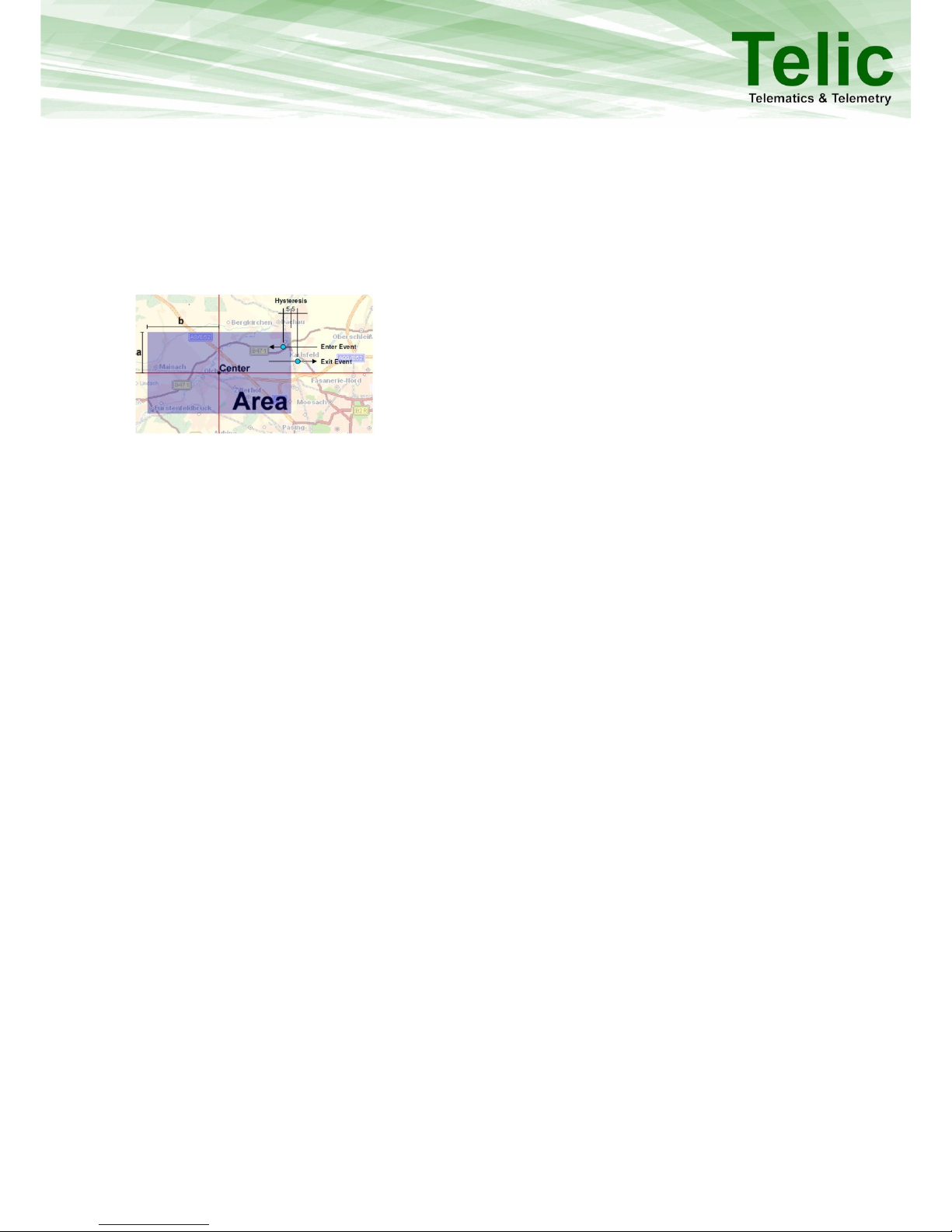
8.1 Geofencing
Figure 8: Geofencing
Geofencing (an electronic safety fence) provides the opportunity to set a geographic square around a
defined location. Here you can set different scenarios like “leaving the area” or “entering the area”
and transmit an event to the control centre. With the SBC-AVL you can monitor 50 geofence areas
which can also be combined to create larger areas and build up a complex protection zone.Every
geofence area is given an Area ID, a center (defined by its longitude and latitude) and a height and
width (from the center not completely across) in meters.
8.2 Roaming alternative configuration
The device is able to detect a GSM roaming status and swap automatically to an alternative setup for
roaming (this alternative setup has to be previously configured). This allows optimizing the data
traffic and reducing the communication costs.
8.3 Input alternative configuration
The device is autonomously able to handle an alternative setup when a specific input is triggered
(this alternative setup has to be previously configured). This can support features like “panic button”.
8.4 Device Watchdogs
The SBC-AVL has different integrated watchdogs. They automatically check the functions of the
device and generate resets as soon as they recognise any malfunction. Malfunction could occur due
to internal problems of the device, problems related to the GSM connection, problems with the GPS
reception and many more.
This watchdog concept ensures that the SBC-AVL can automatically return to stable operation if
necessary. Control of the watchdogs by the user is not necessary.
If the watchdog has to restart the device it may happen that some of the position messages and
respectively events are not logged and as a result they are not transmitted to the tracking server.
Page 18

dfdfdsf
18
8.5 GSM Jamming detection feature
The SBC-AVL Power is able to detect a GSM jamming attempt and activate therefore the digital
output, which can be configured to a siren or light of the vehicle to generate an alert. A specific
event will be generated and transmitted to the receiver as soon as the GSM network coverage
returns available
8.6 Glonass enabling
The SBC-AVL Power obtains the fix per default based on GPS system. It is possible to send a
command in order to force the device to use the GLONASS positioning system instead of GPS.
8.7 1-Wire
A 1-wire interface is available on the SBC-AVL Power, which allows ID-Button for driver recognition
and the connection of up to 8 temperature probes. The following Temperature sensors are
supported:
DS18S20; DS18B20; DS1921G
8.8 CAN Bus (Only for SBC–AVL)
Any CAN BUS hardware can be interfaced to the device in order to extract additional information
from the CAN bus line of the vehicle. Main applications are related to FMS standard for trucks or
ODBII for cars. Dedicated configurations can be defined to retrieve additional data from the CAN bus.
Please contact Telic technical support to discuss in more detail your use case requirements.
8.9 RS232 (Only for SBC–AVL Power)
The SBC-AVL Power supports transparent mode for the RS232 interface, and can therefore interface
with a wide range of external peripheral devices.
The RS232 interface supports TTL Low Voltage (at 3.3 V). An external level shifter is required to
support 12V RS232 logic level.
8.10 Additional Features
A lot of additional features are available on SBC-AVL. Please contact the Telic
Technical Pre-Sales support in case that your specific use case requires
features which aren’t described in this document.
Page 19
dfdfdsf
19
9 Connect to the vehicle
This paragraph describes the procedure to install the device on board of your vehicle and check if the
installation has been performed properly
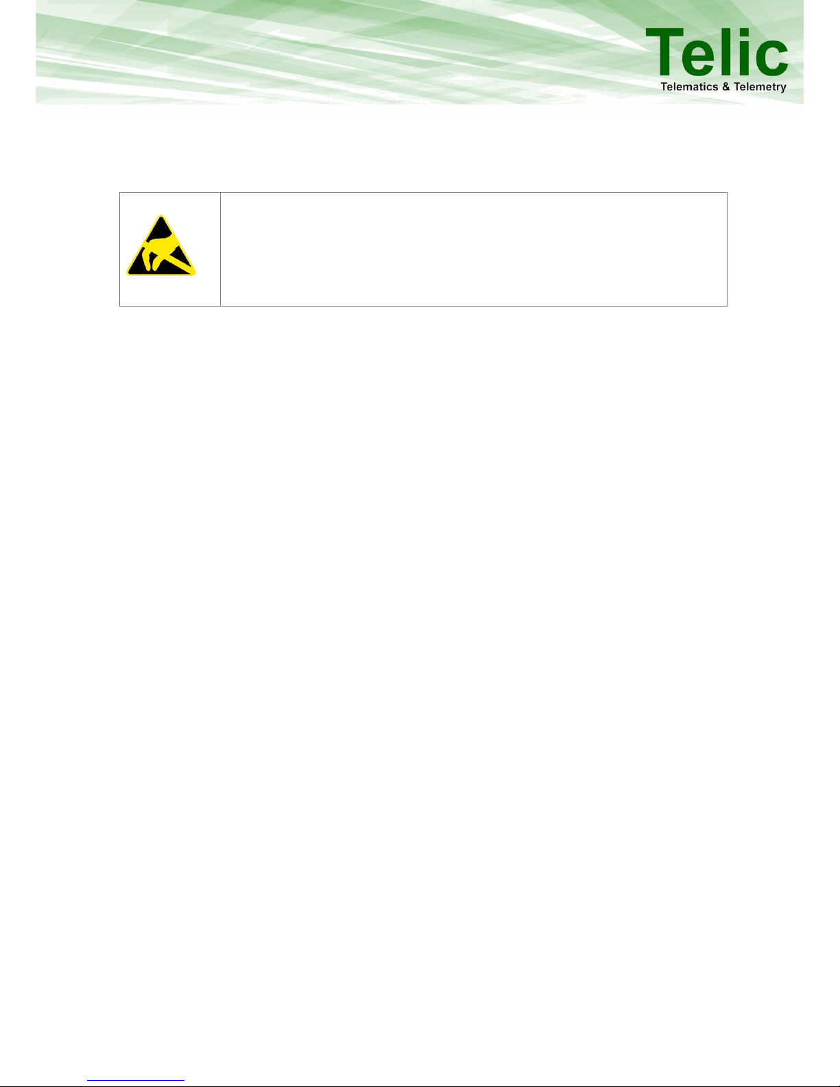
Please take proper ESD protection measures (e.g. electrical connection of the
body to ground) to make sure you don’t destroy internal electronics! Repair of
ESD damages caused by users negligence will not be covered by Telic’s
warranty. Electrostatic discharge (ESD) is the sudden and momentary electric
current that flows between two objects at different electrical potentials
normally caused by static electricity.
9.1 Placing the device into the vehicle
In order to protect your vehicle from theft and vandalism the device should be installed in a location
where it and its power supply are well-hidden. Using the cable-cases on box surfaces, please install
the device in a suitable, dry location, not in contact to radio and audio frequency interference or hot
parts of the vehicle like near the engine. When installing the device please consider that antennas
are integrated, this means it must be installed in a place with a minimum distance of 7 cm to metallic
components of the vehicle in each direction. In order to optimize the quality of the signal received,
the surface of the internal GPS internal antenna must be installed looking at the sky (see the label
indication on the device box-this side up).
9.2 Wiring connection
Please connect the Telic SBC-AVL remote control unit to the vehicle according to the following
instructions using the connection cable. Please do not connect the connector to the Telic SBC-AVL
remote control unit before all cables you intent to use are connected to the vehicle. The power
supply has to be available while the ignition is off.
The black wire (pin 6 on molex connector) must be connected to the GROUND (pin 31 of the vehicle)
and the red wire (pin 1 on molex connector) must be connected to VCC (pin 30 of the vehicle).
The yellow wire (pin 5 on molex connector) must be connected to ignition (pin 15 of the vehicle).
All other wires have to be connected to the related interface, otherwise please ensure that they can
not cause short circuit.
The advantage of constant power supply is that the device is able to connect faster to the GSM
network and it can find faster a new GPS position after ignition was switched from “OFF” to “ON”.
This means that for example working time calculations will be more precise. With ignition off the
power consumption of the Telic SBC-AVL is low enough that it does not interfere with proper
functionality of the vehicle battery.
If the Telic SBC-AVL remote control unit is configured to use a motion dependent power mode, the
device can detect and report that it is moving (e.g. if it is stolen or being transported via a second
vehicle) even while ignition is off.
Page 20

dfdfdsf
20
10 Safety
The following guidelines must be followed in order to ensure the safety of users. If these rules are
ignored Telic will not assume responsibility for any damages that are encured.
10.1 General Battery handling
Because the SBC-AVL main power source is a battery with high energy content. They are designed to
represent the highest possible degree of safety. They may, however, present a potential hazard if
they are abused electrically or mechanically. This is in most circumstances associated with the
generation of excessive heat. In this case the internal pressure may cause the cell case to rupture.
As a result the following general guidelines should be followed when handling the SBC-AVL Battery:
Do not short-circuit
Do not over discharge
Do not incinerate
Do not expose to temperatures beyond the specified
temperature range
Do not crush or puncture
Do not open cells, do not disassemble battery packs
Do not expose contents to water
Do not connect with false polarity
Do not weld or solder to the battery’s body
It is very important that only authorized official Telic replacement batteries be used in the SBC-AVL.
Also the batteries included with the devices are only tested or authorized for use in the SBC-AVL.
The batteries should never be used in any other devices unless specifically authorized by Telic,
including but not limited to other Telic products or devices.
10.2 Battery storage
Batteries should be stored in rooms with generally low temperature and low humidity levels. While it
is not essential that these storage areas be temperature and humidity controlled, temperatures
should generally be kept below 35 °C and storage areas should be well ventilated. Storage
temperatures above 75 °C should be avoided.
Your SBC-AVL batteries should be stored in their original packaging materials or in the SBC-AVL itself.
This will eliminate unintentional shorting. Do not store batteries in conductive anti-static bags or
foam unless the resistivity of the material exceeds 1 MΩ. Batteries should not be placed on or
covered with metallic or otherwise conductive material.
Batteries should be stored away from any flammable material in the storage area. Fire extinguishers
for metal fire (class D) are preferred. Do not attempt to extinguish fires with small amounts of water,
sand, or with carbon dioxide extinguishers.
Page 21

dfdfdsf
21
10.3 Battery disposal
The disposal or recycling of batteries is regulated by each European country. In each country, the
manufacturers, importers and users are responsible for the proper disposal. The European
Community (EC) has issued two directives, 91/157/EEC and 93/86/EEC. These directives are
implemented by each member country of the EC independently and in a different way. In
accordance with these directives, The SBC-AVL Batteries do not contain dangerous substances. The
reaction products are inorganic and do not represent environmental risks once the decomposition
process has terminated.
Page 22

dfdfdsf
22
11 General Terms and Conditions
All information in this documentation has been carefully assembled and checked, but should not be
considered as a guaranteed feature set. The copyright of the related documentation is with Telic
GmbH.
The Telic Logo and the terms Telic, and Telic SBC-AVL are brands of Telic GmbH.
All further names and terms used can be brands or registered brands of their respective owners.
Telic preserves the right to change the included information without notice and doesn’t take
responsibility for errors in the document and/or missing information.
Page 23
dfdfdsf
23
12 Documentation change LOG
Revision
Date
Changes
Rev. 2.0
06/02/14
First release on new layout
Rev. 2.1
26/05/14
Layout Update
Rev. 2.2
25/08/14
Updated SBC-AVL specific information
Rev. 2.3
01/01/15
Updated Sections 1, 4 and 5.4.1.
New Chapter 2 to identify applicable products.
Rev. 2.4
05/07/15
Updated Sections 3 & 4
Table 10: Documentation change LOG
 Loading...