

Page 1

( 1 / 24 )
D4159008A
CCD Camera
CleverDragon series
CSCS20BC2
Specification
CONTENTS
Restriction For Use······························································2
Exemption Clauses ······························································3
Notes on using this product··················································4
1. Overview ·········································································7
2. Features············································································7
3. Configuration···································································8
4. Option parts ·····································································8
5. Function···········································································8
6. Specification ··································································13
7. Timing Chart··································································17
8. Guarantee·······································································22
9. Repair ············································································22
10. External-view Drawing ················································ 23
Page 2

( 2 / 24 )
D4159008A
Restriction For Use
• Should the equipment be used in the following conditions or environments, give consideration to safety
measures and inform us of such usage:
1. Use of the equipment in the conditions or environment contrary to those specified, or use outdoors.
2. Use of the equipment in applications expected to cause potential hazard to people or property, which
require special safety measures to be adopted.
• This product can be used under diverse operating conditions. Determination of applicability of equipment
or devices concerned shall be determined after analysis or testing as necessary by the designer of such
equipment or devices, or personal related to the specifications. Such designer or personal shall assure the
performance and safety of the equipment or devices.
• This product is not designed or manufactured to be used for control of equipment directly concerned with
human life (*1) or equipment relating to maintenance of public services/functions involving factors of
safety (*2). Therefore, the product shall not be used for such applications.
(*1): Equipment directly concerned with human life refer to:
Medical equipment such as life-support systems, equipment for operating theaters.
Exhaust control equipment for exhaust gases such as toxic fumes or smoke.
Equipment mandatory to be installed by various laws and regulations such as the Fire Act or
Building Standard Law.
Equipment related to the above.
(*2): Equipment relating to maintenance of public service/functions involving factors of safety refer to:
Traffic control systems for air transportation, railways, roads, or marine transportation.
Equipment for nuclear power generation.
Equipment related to the above.
Although sufficient check is performed about translation of these specifications, we will apply a
Japanese sentence, if a doubt should occur.
Page 3

( 3 / 24 )
D4159008A
Exemption Clauses
• TELI assumes no responsibility or liability for damage arising from fire, earthquake, an act by a third party
or other accidents, or intentional or careless error or misuse by the user, or use under abnormal conditions.
• TELI assumes no responsibility or liability for incidental damages (e.g., loss of business profits or
interruption of business) arising from use of or inability to use the camera equipment.
• TELI assumes no responsibility or liability in the case damages or losses are caused by failure to observe
the information contained in the operation manual and specifications.
• TELI assumes no responsibility or liability in the case damages or losses are caused by use contrary to the
instructions in this operation manual and specifications.
• TELI assumes no responsibility or liability in the case damages or losses are caused by malfunction or
other problems resulting from use of equipment or software that is not specified.
• TELI assumes no responsibility or liability in the case damages or losses are caused by repair or
modification conducted by the customer or any unauthorized third party (such as an unauthorized service
representative).
• Expenses we bear on this product shall be limited to the individual price of the product.
• TELI does NOT guarantee the items that are not described in the specification.
Page 4
( 4 / 24 )
D4159008A
Notes on using this product
• Handle carefully
Do not drop the equipment or allow it to be subject to strong impact or vibration, as such action may
cause malfunctions. Further, do not damage the connection cable, since this may cause wire breakage.
• Environmental operating conditions
Do not use the product in locations where the ambient temperature or humidity exceeds the
specifications.
Otherwise, image quality may be degraded or internal components may be adversely affected. In
particular, do not use the product in areas exposed to direct sunlight. Moreover, during shooting under
high temperatures, vertical stripes or white spots (noise) may be produced, depending on the subject or
camera conditions (such as increased gain). However, such phenomena are not malfunctions.
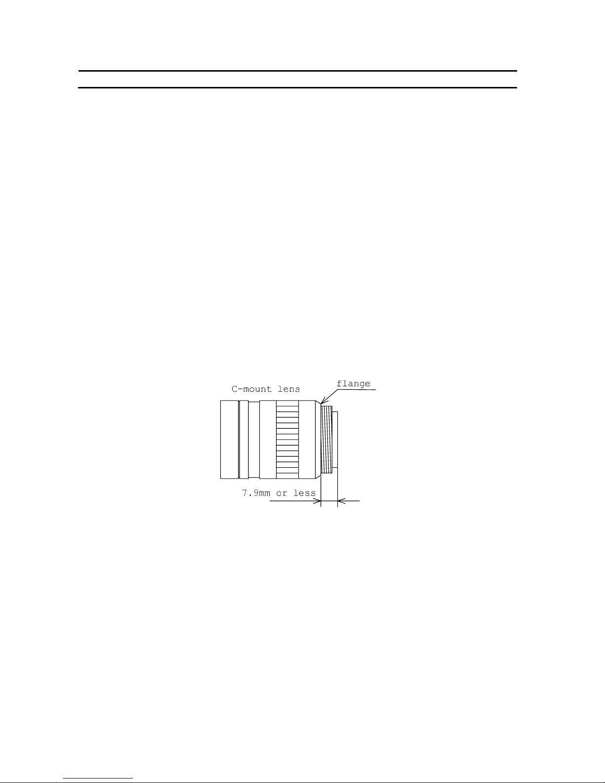
• Regarding a lens mount
Install a next lens; the C mount lens, its dimension of protrusion from flange is equal to or less than 7.9
mm. If a lens does not stand to this condition, it might not be installed to this camera.
• Check a combination with the lens
Depending on the lens and lighting you use, an image is reflected as a ghost in the imaging area.
However, this is not because of a fault of the camera.
In addition, depending on the lens you use, the performance of the camera may not be brought out
fully due to deterioration in resolution and brightness in the peripheral area, aberration and others.
Be sure to check a combination with the camera by using the lens and lightning you actually use.
When installing a lens in the camera, make sure carefully that it is not tilted.
In addition, use a mounting screw free from defects and dirt. Otherwise, the camera may be unable to
be removed.
Page 5

( 5 / 24 )
D4159008A
Notes on using this product
• Avoid intensive light
Do NOT expose the camera's image-pickup-plane to sunlight or other intense light directly. If the part
of CCD is exposed to spot-intensive light, you might get a picture problem like blooming and/or smear.
Under the comparison at the same video output level, the shorter the exposure time setting, the more
smear is generated.
• Do not expose the camera’s image-pickup-plane to sunlight or other intense light directly.
Its inner CCD (charge-coupled device) might be damaged.
• Occurrence of moire
If you shoot thin stripe patterns, moire patterns (interference fringes) may appear. This is not a
malfunction.
• Occurrence of noise on the screen
If an intense magnetic or electromagnetic field is generated near the camera or connection cable, noise
may be generated on the screen. If this occurs, move the camera or the cable.
• Handling of the protective cap
If the camera is not in use, attach the lens cap to the camera to protect the image pickup surface.
• If the equipment is not to be used for a long duration
Turn off power to the camera for safety.
• Maintenance
Turn off power to the equipment and wipe it with a dry cloth.
If it becomes severely contaminated, gently wipe the affected areas with a soft cloth dampened with
diluted neutral detergent. Never use alcohol, benzene, thinner, or other chemicals because such
chemicals may damage or discolor the paint and indications.
If the image pickup surface becomes dusty, contaminated, or scratched, consult your sales
representative.
Page 6

( 6 / 24 )
D4159008A
CAUTIONS ON USE
• When disposing of the camera
Wastes of this product should be separated and discarded in compliance with the various national and
local ordinances.
This camera is showing the following symbol to body due to EU environmental regulation (Waste
Electrical and Electronic Equipment (WEEE)). However this symbol is applied to only a EU member
state.
Page 7

( 7 / 24 )
D4159008A
1. Overview
CleverDragon series CSCS20BC2 is an integrated type B/W CCD camera with a SXGA format
all-pixel-data readout CCD. The model is suited for high-resolution image processing use. Its compact,
light-weight body is ideal for system integration.
2. Features
(1) All-pixel reading
The all-pixel reading system allows the CSCS20BC2 to read all pixels in just 1/19.5 second.
CSCS20BC2 is equipped with a full-frame shutter that allows all-pixel reading even during shutter
operations.
(2) Full-frame shutter
Since all pixels are output even by a random trigger shutter operation, high resolution can be achieved,
without deteriorating the vertical resolution.
(3) Tetragonal lattice layout
The tetragonal lattice layout of CCD pixels facilitates computation for image processing.
(4) Camera Link interface (power supply type)
By using a Camera Link-capable frame grabber board to which power can be supplied, high-speed
transfer of captured images to a PC as well as various types of camera control from the PC are allowed.
Power can also be supplied to the camera with only one cable.
(5) Random trigger shutter function
CSCS20BC2 is equipped with a random trigger shutter, which starts exposure synchronized with
external trigger signals. Fast-moving objects can thus be captured in place, which ensures accurate
image processing.
(6) Restart-Reset
Images can be shot and fetched at arbitrary timing based on external VD signal input.
(7) Partial scan
Further speed-up is possible because ranges except the range of the image output that the user set are not
read.
(8) Ultra-compact and lightweight main unit
The space-saving ultra-compact and lightweight camera has excellent resistance against vibration and
impact.
(9) RoHS compliant
CleverDragon series are complied with EU RoHS.
Page 8

( 8 / 24 )
D4159008A
3. Configuration
Camera body ............................................................................................. 1
Operation Manual (Japanese) ................................................................... 1
Operation Manual (English) ..................................................................... 1
4. Option parts
(1) Camera mounting kit CPT8560
*NOTE: Contact your dealer / distributor for details of option units.
*NOTE: Application software is not supplied as a standard item.
5. Function
5-1. Serial communication control
By CameraLink serial communication interface, it is possible to control the following functions.
(1) Set-up Addition Value 10bit: +0 to +255 [digit]
8bit: +0 to +63 [digit]
(2) Gain 0dB to Approx. +12dB
(3) Shutter Speed 2[sec] to 1/20,000[sec]
(4) Random Trigger Shutter ON / OFF
* Restart-Reset mode must be disabled.
・Trigger / VD Polarity Positive / Negative
・Random Trigger Mode Fix / Pulse Width
(5) Restart-Reset ON / OFF
* Random Trigger Shutter mode must be disabled.
(6) Partial Scan Video output start line, Video output width
Minimum width: 512H
5-2. Power supply from PoCL cable
Pin 1, 26 +12V±10% (ripple level: 50mV
P-P
or less)
Page 9

( 9 / 24 )
D4159008A
5-3. Command Communication Protocol
The command communication protocol is the teli standard method (method in which parameters are set
in the registers in the camera).
In command send/receive operation, hexadecimal address and data are converted to ASCII data.
All ASCII alphabetic characters used are uppercase characters.
(1) Write to a register
To write data in a register, send a command, as follows. (Address' max-length is 2 bytes, and Data's
max-length is 8 bytes)
For example, to write data 0x38 to address 0x76, send a command, as follows:
The camera responds to the write command with No Error (ACK) or Error (NAK), as follows:
No Error (ACK):
Error (NAK):
*Because two kinds of data is needed for the setting about the Partial Scan, the register writing for "Set
value application" is separately needed.
Address
2nd byte
Address
1st byte
‘ , ’
(0x2C)
Data
8th byte
Data
7th byte
Data
6th byte
Data
5th byte
Data
4th byte
Data
2nd byte
Data
1st byte
[CR]
(0x0D)
Data
3rd byte
‘7’
(0x37)
‘6’
(0x36)
‘ , ’
(0x2C)
‘3’
(0x33)
‘8’
(0x38)
[CR]
(0x0D)
[ACK]
(0x06)
[CR]
(0x0D)
[NAK]
(0x15)
[CR]
(0x0D)
Page 10

( 10 / 24 )
D4159008A
(2) Reading the register
To read data from a register, send ', (comma)', 'R', 'Q' and [CR] code following the address. For example,
to read data in address 0x91, send a command, as follows:
The camera responds to the read request, as follows (Data's max-length is 8 bytes):
Actually, the camera responds to the read request as minimum data length: For example, to read data
0x10 to address 0x91, the camera responds as follows:
‘9’
(0x39)
‘1’
(0x31)
‘ , ’
(0x2C)
‘R’
(0x52)
‘Q’
(0x51)
[CR]
(0x0D)
Data
8th byte
Data
7th byte
Data
6th byte
Data
5th byte
Data
4th byte
Data
2nd byte
Data
1st by te
[CR]
(0x0D)
Data
3rd byte
‘1’
(0x31)
‘0’
(0x30)
[CR]
(0x0D)
Page 11

( 11 / 24 )
D4159008A
5-4. Register Map
0x00
0x0F
R.O.
Maker Name
ASCII Format
0x10
0x2F
R.O.
Maker Name
TOSHIBA TELI
Model Name
CSCS20BC2
0x30
0x3F
R.O.
Serial Number
ex) 0100011
0x40
0x47
R.O.
0x48
0x4F
R.O.
0x50
0x57
R.O.
0x58
0x5F
N.A.
N.A.
|
Reserved
Reserved
0x60
0x67
R.O.
0x68 N.A.
Reserved
0x69 R.O.
0x6A R.O.
0x6B N.A.
0x6C R.O.
0x6D W.O.
0x6E R/W
0x6F W.O.
0x70 R/W
0x71 N.A.
|
0x75 N.A.
0x76 R/W
0x77 N.A.
|
0x7F N.A.
Firmware Version
ex) 01.01.01
||
|
|
|
|
|
|
|
|
|
Address
Read
Write
B&W Camera
CSCS20BC2
R/W Read/Write
R.O. Read Only
W.O. Write Only
N.A. Not Available
Model Name
ASCII Format
Serial Number
ASCII Format
Firmware Version
ASCII Format
FPGA Version
ASCII Format
CPLD1 Version
ASCII Format
Register Map Version
ASCII Format
Status
Expanded Status
Reserved
Memory Bank Confirmation
Save to Memory
Load from Memory
Initialize Memory
Setup (Offset) Addition Value
Reserved
Reserved
|
Gain
Reserved
Reserved
|
FPGA Version
ex) 01.01.01
CPLD1 Version
ex) 01.01.01
Register Map Version
ex) 01.01
Status
Status information after Camer a Controlling
Expanded Status
Detail information of the status
Memory Bank Confirmation
The information of memory banks the setting saved.
0x01(Saved), 0x00(Not saved)
Saved to Memory
Write 0x01 : Save the current camera settings.
The camera uses saved settings after rebooting.
Read from Memory
Write 0x01 : Load saved settings.
Initialize Memory
Write 0x01 : Delete saved user settings.
Setup (Offset) Addition Value
0-255
Default : 0
Gain
0(0dB)-90(Approx.+12dB)
Default : 0(0dB)
Page 12

( 12 / 24 )
D4159008A
0x80 R.O.
0x82 R.O.
0x84 R.O.
0x86 N.A.
0x87 R/W
0x90 R/W
0x9F
0xA0
N.A.
R/W
0xA2 N.A.
0xC0 W.O.
0xBF N.A.
0xC4 R/W
0xC6 N.A.
|
0xC7 N.A.
0xC8 R/W
0xCA
|
0x8F N.A.
0x91 R/W
0x92 R/W
0x93 R/W
0x94 N.A.
|
0xA3 N.A.
0xA4 R/W
0xA5 N.A.
0xC1 N.A.
|
0xC3 N.A.
|
|
|
|
|
0x88 N.A.
0xFF
Frame Rate (@Normal Shutter)
Normal : 19fps
Partial : The calculation from partial video width.
(Omit it after the decimal point. )
Default : 19fps @ Normal Scan
Address
Read
Write
B&W Camera
CSCS20BC2
N.A.
|
N.A.
R/W Read/Write
R.O. Read Only
W.O. Write Only
N.A. Not Available
Reserved
Reserved
|
Video Width @ Partial Scan
Reserved
Reserved
Video Start Line @ Partial Scan
Reserved
Reserved
|
Partial Scan Update
Reserved
Reserved
|
Shutter Speed (numerator)
Reserved
Reserved
Shutter Speed (denominator)
Reserved
Reserved
|
Trigger Polarity
Random Trigger Shutter Mode
Shutter Mode
Scan Mode
Reserved
Reserved
|
Output Bit
Reserved
Vertical Resolution
Horizontal Resolution
Frame Rate
Horizontal Resolution
1360 (fixed)
Vertical Resolution
1024 @ Normal Scan
Video Width @ Partial Scan
Default : 1024 @ Normal Scan
Output Bit
8(8bit),10(10bit)
Default : 8(8bit)
Scan Mode
0(Normal),1(Partial)
Default : 0(Normal)
Shutter Mode
0(Normal Shutter),1(Random Trigger),2(Restart Reset)
Default : 0(Normal Shutter)
Random Trigger Shutter Mode
0(Fix),1(Pulse Width)
Default : 0(Fix)
Trigger Polarity
0(Nega),1(Posi)
Default : 0(Nega)
Shutter Speed (denominator)
1-20000
Default : 19
Shutter Speed (numerator)
1-255
Default : 1
Partial Scan Update
Write 0x01 : Update registers related with Partial Scan
Video Start Line @ Partial Scan
0-512
Default : 0
Video Width @ Partial Scan
512-1024
Default : 1024
Page 13

( 13 / 24 )
D4159008A
6. Specification
[Electrical specification]
(1) Imager all-pixel-data-readout interline transfer CCD
Number of total pixels 1434(H) × 1050(V)
Number of effective pixels 1392(H) × 1040(V)
Number of Video out pixels 1360(H) × 1024(V)
Scanning area 6.47mm(H) × 4.84mm(V)
(= Equivalent to 1/2” type CCD size)
Pixel size 4.65µm(H) × 4.65µm(V) (Square-grid array)
(2) Scan method Non- interlace
(3) Synchronization method Internal synchronization
(4) Aspect ratio 4:3
(5) Video Output Compliant with CameraLink standard version 1.2
Data 10 / 8 bit switching (factory default: 8bit)
Readout mode
All pixel readout (factory default) 1360(H) × 1024(V) [Approx. 19.5fps]
Partial Scan (ex.1) 1360(H) × 768(V) [Approx. 25.0fps]
(ex.2) 1360(H) × 512(V) [Approx. 34.8fps]
minimum lines: 6512, minimum step: 1 line
(6) Sensitivity 500 lx, F5.6
(7) Minimum subject illuminance 5lx F1.4 (GAIN: 10dB, video level: 50 %)
(8) Gain 0 to Approx. +12 dB [1step= Approx. 0.132dB]
(9) Setup Level (factory default) 40 ± 20 [digit] (10bit)
10 ± 5 [digit] (8bit)
(addition value) +0 to +255 [digit] (10bit, 255 steps)
+0 to +63 [digit] (8bit, 255 steps)
(10) Gamma correction OFF (γ = 1.0 fixed)
(11) Power supply voltage DC12V ± 10% (ripple 50mV
P-P
or less)
(12) Power consumption Approx. 1.8W (*Tentative)
[Internal sync signal specification]
(1) Driving frequency 36.00 MHz (1 CLK) ±100ppm
(2) Horizontal sync frequency 20.11 kHz (1H = 1790CLK)
(3) Vertical sync frequency 19.49 Hz
(maximum frequency on all pixel readout mode)
Page 14

( 14 / 24 )
D4159008A
[Electrical shutter specification]
(1) Shutter Speed 2/1 to 1/20,000 [sec]
Setting format: Numerator / Denominator [sec]
Numerator: 1 to 255
Denominator: 1 to 20,000
*When you set the exposure time longer than approximately 1 second, white spots and the
unevenness in highlight portion might occasionally be observed on screen. This phenomenon is
due to the characteristics of the CCD image-pickup device, and do not reflect performance error in
the pickup device or CCD Camera itself.
(2) Random Trigger Shutter ON / OFF switching (factory default: OFF)
・Fixed mode The exposure time depends on the shutter speed setting
・pulse width mode The exposure time depends on the pulse width.
(3) Restart-Reset ON / OFF switching (factory default: OFF)
The exposure time depends on the period of Ext. VD.
[Input signal specification]
(1) TRIG/VD Camera Link interface input: CC1
・Polarity Positive/Negative switching (factory default: Negative)
・Pulse width 8µs to 2s
[Camera PSU input impedance]
Ci <
57µF, Rx =10kΩ±10%
PoCL
Cable
PSU
Test Circuit
CSCU15BC18
PSU
Camera
PSU
Ia
Rx Cx
Vb
I a = 52uA, Vb = 0.52V, Cx < 50uF
Pin#: 1, 26
Pin#: 13, 14
Page 15

( 15 / 24 )
D4159008A
[Mechanical spec]
(1) Lens mount C-mount
*Install a next lens; the C mount lens, its dimension of protrusion from flange is equal to or less than
7.9 mm. If a lens does not stand to this condition, it might not be installed to this camera.
*Depending on the lens you use, the performance of the camera may not be brought out fully due to
the deterioration in resolution and brightness in the peripheral area, occurrence of the ghost,
aberration and others. When you check the combination between the lens and camera, be sure to use
the lens you actually use.
(2) Flange back 17.526 mm
(3) Dimensions 29mm(W) × 29mm(H) × 26.5mm(D)
* Not including protrusion
(4) Mass Approx. 40g
(5) Camera body grounding: insulation status Conductive between circuit GND and camera body
[Operating ambient conditions]
(1) Performance assurance Temperature: 0°C to +40°C
Humidity: 10% to 90% (no condensation)
(2) Operation guaranteed Temperature: -5°C to +45°C
Humidity: 90% or less (no condensation)
(3) Storage Temperature: -20°C to +60°C
Humidity: 95% or less (no condensation)
(4) EMC conditions (Electro-Magnetic Compatibility)
EMI (Electro-Magnetic Interference)
EN61000-6-4 (Conformity is planned.)
EMS (Electro-Magnetic Susceptibility)
EN61000-6-2 (Conformity is planned.)
(5) FCC
FCC Part 15 Subpart B class A (Conformity is planned.)
*About the conformity of EMC standard of this machine, it has guaranteed in the conditions
combined with our system condition. When used combined parts other than specification of our
company, I ask you to have final EMC conformity checked of a visitor with a machine and the whole
equipment.
Page 16

( 16 / 24 )
D4159008A
[Communication specification]
(1) Communication speed 9600 bps (fixed)
(2) Start bit 1
(3) Data bit 8
(4) Parity None
(5) Stop bit 1
(6) Handshake None
[Connector pin assignment]
Video output/controlling/power supply connector: (Camera Link Base Configuration) CAMERA LINK
Connector model: HDR-EC26FDTG2+ (Manufactured by Honda Connectors)
Pin # I/O Signal name Pin # I/O Signal name
1 - +12V 14 - GND
2 O TxOUT0- 15 O TxOUT0+
3 O TxOUT1- 16 O TxOUT1+
4 O TxOUT2- 17 O TxOUT2+
5 O TxCLK OUT- 18 O TxCLK OUT+
6 O TxOUT3- 19 O TxOUT3+
7 I SerTC(RxD)+ 20 I SerTC(RxD)8 O SerTFG(TxD)- 21 O SerTFG(TxD)+
9 I CC1(TRIG/VD)- 22 I CC1(TRIG/VD)+
10 I CC2+ 23 I CC211 I CC3- 24 I CC3+
12 I CC4+ 25 I CC413 - GND 26 - +12V
*Please confirm the power supply of the camera cuts when the connector is connected or pulls out.
It causes the breakdown etc.
[Typical ambient conditions]
*The lens characteristics and light source characteristics are not reflected in table.
0.0
0.1
0.2
0.3
0.4
0.5
0.6
0.7
0.8
0.9
1.0
400 500 600 700 800 900 1000
Wave Length[nm]
Relative Response
Page 17

( 17 / 24 )
D4159008A
7. Timing Chart
7-1. Normal Scan (All pixel readout)
As all pixels are read out in approx. 1/19.5s, you will get images with the higher V resolution
(you have to change the shutter speed to 1/19.5s or shorter).
LVAL
DVAL
b
DATA OUT
a = 336CLK b = 22CLK c = 16CLK d = 1360CLK f = 40CLK
c
e = 16CLK
d
e
f
FVAL
Same timing
FVAL
DATA OUT
LVAL
DVAL
A B
B = approx. 50.9ms (1024H-336CLK)
Vertical Timing (maximum speed on all pixel readout mode)
Horizontal Timing
C
1frame = A + B + C = approx. 51.3ms
*1H = 1790CLK
A = approx. 271.1us
a
C = approx. 136.0us
Page 18

( 18 / 24 )
D4159008A
7-2. Partial Scan
Ranges except the range of the image output that the user set are not read.
ex.1) Video Start Line =128, Video Width = 768
(maximum speed on all pixel readout mode)
FVAL
DATA OUT
LVAL
DVAL
A B C
A = approx. 996.4us B = approx. 38.2ms ( 768H-336CLK ) C = approx. 861.3us D = approx. 40.0ms
D
Video output:768 lines
Video start line:128
Not read
Video width:768 lines
The rest of line:128
Not read
Video output
Valid lines:1024
Page 19

( 19 / 24 )
D4159008A
ex. 2) Video Start Line =256, Video Width=512
(maximum speed on all pixel readout mode)
FVAL
DATA OUT
LVAL
DVAL
A B C
D
A = approx. 1721.8us
B = approx. 25.5ms (512H-336CLK)
C = approx. 1586.7us
D = approx. 28.8ms
Video output:512 lines
Video start line:256
Valid lines:1024
Not read
Video width:512 lines
The rest of line:256
Not read
Video output
Page 20

( 20 / 24 )
D4159008A
7-3. Random Trigger Shutter
In the random trigger shutter mode, you can shoot and grab an image at an arbitrary timing by trigger
signal input from the external (It is not possible to use the Random Trigger Shutter concurrently with the
Restart Reset mode).
· External trigger signals can be input either from the camera link I/F CC1.
· If polarity is set to negative polarity, exposure starts at the falling edge of the trigger.
· The random trigger shutter of this camera can be operated in two types of mode: fixed mode and pulse
width mode. How to determine the exposure time differs depending on the mode.
z Fix mode
The exposure time is determined by the setting value for the shutter speed.
· Pulse Width mode (Trigger Polution:Low Active)
The exposure time is determined by the pulse width
Set a pulse width of 1H (approximately 49.7µs) or more.
Page 21

( 21 / 24 )
D4159008A
7-4. Restart / Reset
The restart / reset function is available with the ext.VD signal. You can get an arbitrary slower shutter
speed than normal shutter and random trigger shutter (It is not possible to use the Restart Reset mode
concurrently with the Random Trigger Shutter mode).
· External VD signals can be input either from the camera link I/F CC1.
· The shutter speed (exposure time) is determined by ext. VD signal interval.
· The image is outputted behind time for a maximum of 1.0H from an external VD signal.
1) Vertical Timing
CCD
exposure
DATA OUT
FVAL
VD
2) Horizontal Timing
DAT A OUT
CCD
exposure
Ext. VD input
FVAL
more than 1H
when the external VD inputs to the camera while video output
Page 22

( 22 / 24 )
D4159008A
8. Guarantee
The term of a guarantee is one year after the product delivery.
If by any chance trouble by responsibility of our company occurs before an above period, TELI repairs
it free of charge.
- During terms of a guarantee, when the trouble cause is the case of below, TELI charges the repair
costs.
(1) Troubles and the damages that causes by misuse, unsuitable repair or remodeling.
(2) Distribution hazards like drops and vibrations after purchase. Troubles and damages by
transportation.
(3) Troubles and damages by fire, natural calamity (earthquake, storm and flood damage, thunderbolt),
damages from salty breeze, gas harm, abnormal voltage.
9. Repair
9-1. Condition for repair
Basically, has to return it to our company when the user requests us to repair product.
Beside that, customer should pay these expenses (travel expenses, camera disassembly technology costs)
of both customer and end user. Also customer should pay in themselves costs for return camera to us.
9-2. The period of repairing product
(1) Repair free of charge ... Refer to Clause 8.
(2) Charged repair ............. Basically, repair period is 7 years after the last production end of products.
Page 23

( 23 / 24 )
D4159008A
10. External-view Drawing
Page 24

( 24 / 24 )
D4159008A
Head Office: 7-1, 4 chome, Asahigaoka, Hino-shi, Tokyo, 191-0065, Japan
(Overseas Sales Department)
Phone: +81-42-589-8771 Fax: +81-42-589-8774
URL: http://www.toshiba-teli.co.jp
The design and specification is subject to change without notice.
Distributer
 Loading...