

Teli CS8630BH Operation Manual
CCD Monochrome
Video Camera
Operation Manual
Model
CS8630BH
BEFORE USE - GENERAL SAFETY
INSTRUCTIONS
This instruction manual contains important information for the
operator (user) and/or people around him/her to avoid personal
injury, or property damage to him/her or people around him/her by
using this product correctly. Prior to use, read this operation
manual carefully to fully understand its instructions for correct
use.
OWNER’S RECORD
Please fill in the blank below the model name and product serial
number, which is found on bottom chassis of your device. Keep
this number for your record.
Serial No.
WARNINGS & CAUTIONS
[Definition of markings]
The meaning of each mark used in this instruction manual is given
below.
DANGER
CAUTION
Notes
*1 : Personal injuries mean wounds, burns, electric
shocks, and others for which the person injured need
not to be hospitalized nor to be cared for the long
term.
*2 : Material damages mean any direct or consequential
damages related to property or material loss.
This mark indicates what the user SHOULD NOT
DO. The details of things which the user should not
do are described next to this mark.
This mark indicates what the user MUST DO. The
details of things which the user must do are described
next to this mark.
This mark indicates that the user must be alert against
a possible DANGER. The details of the danger which
the user must be aware of are described next to this
mark.
This mark indicates that the user are given a
CAUTION against possible hazards. The details of
the caution which the user must be aware of are
described next to this mark.
●Handling Precautions
MUST
MUST
MUST
MUST
This mark warns the user that improper use,
indicated with this mark, may cause death or
severe personal injuries against the user or
people around him/her.
This mark warns the user that improper use,
indicated with this mark, may cause personal
injuries (*1) or material damages (*2) against
the user or people around him/her.
DANGER
If any overheating sign is observed, discontinue
use immediately.
In the event that smoke, smell, or any other
overheating sign is observed, turn its power
switch OFF immediately, and remove its camera
cable from camera connector. Do NOT try to
continue to use your camera. To do so in spite
of a clear sign of a malfunction invites a fire, an
electric shock hazard, or any other serious
damage. In such case, after confirming that there
is no risk of a fire accident, contact us or our
dealer/distributor through which you purchased
this device for repair service. To avoid hazard, do
NEVER attempt to repair it yourself.
If any malfunctioning sign is observed,
discontinue use immediately.
Do NOT try to use this device when it is
obviously malfunctioning. (Example: No
images on the monitor) In the event of a
malfunction, turn its power switch OFF
immediately, and remove its camera cable from
camera connector. In such case, contact us or our
dealer/distributor through which you purchased
this device for repair service.
If any liquid gets into the device, discontinue use
immediately.
In the event that water, or any other type of
liquid gets into the body, do NOT try to
continue to use the device. To do so invites a f
ire or an electric shock hazard. In such case,
turn its power switch OFF immediately, and
then remove its camera cable from camera
connector. After that, contact us or our
dealer/distributor through which you purchased
this device for repair service/technical advice.
Connection/Disconnection only AFTER
power OFF.
When you connect/disconnect camera
connector, make sure to turn power SW OFF
first. This camera is not designed for “hot plugging”. Do NEVER make
connection/disconnection while power ON.
Doing so might cause a breakdown.
MUST
NEVER
pull apart
DON’T
DON’T
DANGER
Use manufacturer-recommended peripheral
devices (option units) only.
Make sure to use option units specified in this
operation manual only. When connected with
any other non-guaranteed peripheral devices,
your camera might fail to perform its full
capacity. In the worst case, it might cause a fire
or breakdown.
Do NOT disassemble this device.
Do NOT attempt to pull apart, repair, or modify
your camera yourself. To do so might lead to a
fire or an electric shock accident. Contact us or
the dealer/distributor from which you purchased
the device for repair/modification.
Do NOT supply any power other than specified.
This device is designed to work only under
specified voltage. Do NOT attempt to supply
the device with power other than specified.
Supplying the device with any unspecified
power invites a fire or an electric shock hazard.
(CS8600 series --- DC+12V)
Do NOT use the camera in a high-humidity
environment.
Do NOT place your camera near a humidifier,
or in other high-humidity environment. To do so
might cause a fire or an electric shock accident.
●Handling Precautions
CAUTION
If the camera is operated in the electromagnetic
field, there may be cases where beat noises
(vertical, horizontal, or oblique stripes) appear in
the video output. In that case, take preventive
measures on the electromagnetic-wave
CAUTION
generating source so that your camera do not
receive the interference by the
electromagnetic-wave. Take extra precautions
against electromagnetic-wave-interference if
your camera is used with a servomotor, inverter,
or other electromagnetic-wave-generating
equipment.
Avoid giving a strong shock against the camera
body. It might cause a breakdown or damage. If
your camera is used in a system where its camera
CAUTION
head is subjected to strong repetitive shocks, its
camera head is possible to break down. If you
intend to use your camera in such a situation,
make sure to use an optional camera-connector
-fixing-hardware to connect the connector-plug
to the camera body.
When the camera is not in use, put a lens or a
lens-cap onto the camera head so that the image
pickup plane of CCD is protected from dust,
foreign object, or any other flaw-causing object.
If the glass plane (image pickup plane) gets dirty,
clean it with a cotton swab. When it needs to be
CAUTION
cleaned with a cleaner, be sure NOT to use any
organic solvent other than ethyl alcohol. As a
countermeasure against condensation, when the
camera is moved from a warm
condition/environment to a cold one, take
appropriate precautions to prevent condensation
from forming on the camera.
Do not pull strongly the camera
cable/camera-head nor swing it. The stress from
CAUTION
pulling or swinging may cause damage in the
coating of the cable, or breaks in the inside
wires.
Avoid short-circuiting signal output. Otherwise,
it may cause a malfunction.
CAUTION
Do NEVER expose its camera head to any
intensive light (such as direct sunlight).
CAUTION
Otherwise, its inner image pickup device might
get damaged.
This equipment has been tested and found to comply with the
limits for a class A digital device, pursuant to Part 15 of the FCC
Rules. These limits are designed to provide reasonable protection
against harmful interference when the equipment is operated in a
commercial environment. This equipment generates, uses, can
radiate radio frequency energy and, if not installed and used in
accordance with the instruction manual, may cause harmful
interference to radio communications. Operation of this equipment
in a residential area is likely to cause harmful interference in
which case the user will be require to correct the interference at
his own expense.
This device complies with Part 15 of the FCC rules. Operation is
subject to the following two conditions: (1) This device may not
cause harmful interference, and (2) This device accept any
interference received, including interference that may cause
undesired operation.
RESTRICTION FOR USE
In the case where a malfunction of this camera (e.g. video output
cut-off) can be expected to lead to a significant accident, avoid
using this device for such system build-in use.
DISCLAIMER (LIMITED WARRANTY)
We assume no responsibility and shall be held harmless for
damage or loss incurred by the user in the following cases.
1.In the case where damage or loss is caused by fire, earthquake,
or other acts of Gods, acts by a third party, misuse by the user
deliberately or erroneously, or use under extreme operating
conditions.
2.In the case where any indirect, additional, consequential
damages (e.g. loss of expected interest, suspension of business
activities) are incurred as results of a malfunction or
non-functioning of this device, we shall be exempted from
assuming responsibility for such damages.
3.In the case where damage or loss is caused by incorrect use
which is not in line with the instructions given in this
operation manual.
4.In the case where damage or loss is caused by a malfunction
resulting from bad connection with other equipment.
5.In the case where damage or loss is caused by repair or
modification done by the user.
PRODUCT DESCRIPTION
Model CS8630BH is a miniature camera series featuring its
ultra-small light-weight body. The CS8630BH is designed mainly
for factory automation, machine vision, and image measurement
application.
FEATURES
(1) High resolution
The 380,000 pixel CCD realizes the horizontal resolution of
570TV lines.
High-density images with minimum moire-fringes & beatings
are obtained. (CCIR: 440,000 pixels, 560TV lines)
(2) Ultra-compact & light-weight body
The camera features its ultra-small light-weight body. Its super small body will free you from much of your space restriction
problem. The camera is driven by DC12V.
(3) Electronic shutter
The built-in electronic shutter allows this camera to
capture a fast-moving object clearly and sharply.
(4) AGC (Automatic Gain Control)
This series is equipped with AGC function. With the
AGC, the camera obtains optimal images constantly
even when the amount of incoming light fluctuates.
(5) Restart/Reset
When the restart/reset function set ON, the camera
captures images at any timing given by R.R. pulse
input (VD input).
(6) SS (Special shutter) & RTS (Random trigger shutter)
This camera is fitted with special shutter and random trigger
shutter function, which allows the camera to capture images
cued by external trigger input.
(7) Near-infrared region sensitivity
The CCD has a near-infrared-region sensitivity. These models
capture clear images even under near-IR shooting condition.
(8) RoHS compliant
CONFIGURATION
(1) Camera body 1
(2) Accessory
Manual 1
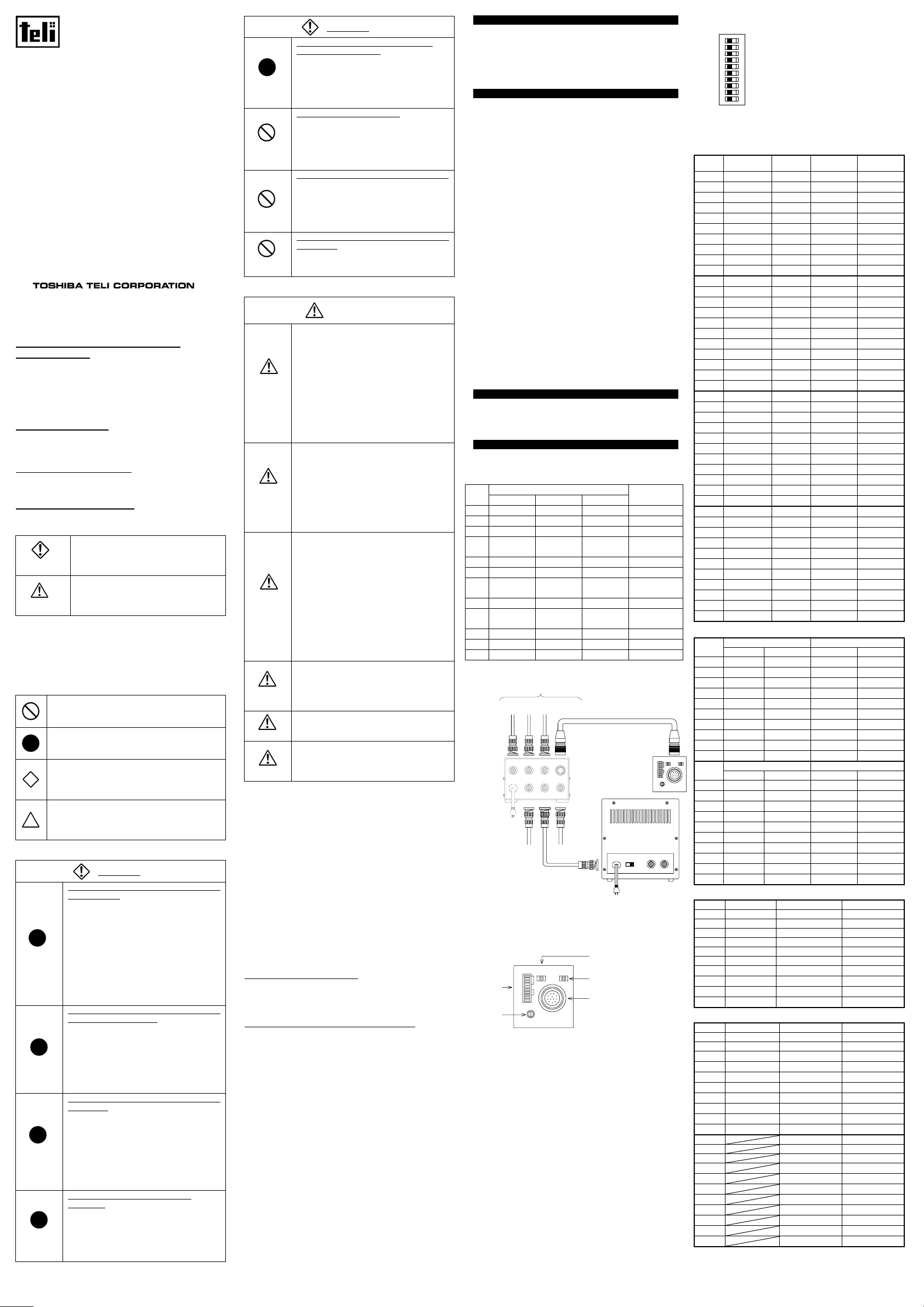
CONNECTION / MODE / REAR-PANEL SWITCH
(1) Connector Pin Assignment
Compatible plug: HR10A-10P-12S
(Manufactured by HIROSE ELEC.)
Pin
No.
HD VD VS/SYNC R.R.
External sync.
Internal sync.
1 GND GND GND GND
2 +12V +12V +12V +12V
3 GND GND GND GND
VIDEO
4
OUT
VIDEO
OUT
VIDEO
OUT
VIDEO OUT
5 GND GND GND GND
6 HD IN ----- HD IN HD OUT*
7 VD IN
VS/SYNC
IN
R.R. IN VD OUT*
8 GND GND GND GND
CLOCK
9
OUT
CLOCK
OUT
CLOCK
OUT
CLOCK
OUT
10 WEN OUT WEN OUT ----- WEN OUT
11 TRIG IN TRIG IN TRIG IN TRIG IN
12 GND GND GND GND
* HD VD output is available via inner SW selection under internal
sync operation.
To be connected if necessary
TRIGGER
VD/VS/SYNC/R.R
HD
(Either one)
Camera Cable (Option)
TRIGGE
R
AC100V IN
HD
WEN
SERIAL No.
VIDEO OUT
VD
CAMERA
CLOCK
OUT
Camera Adapter
CA130D (Rear)
CS8630BH
Rear Panel
EXT INT
ON OFF
HD/VD
75Ω
SHUT
FR/FL
TRIG
γ
M/AGC
VIDEO OUT/
M GAIN
DC IN/SYNC
AC100V
50/60Hz
* Make sure that video output is properly 75-ohm terminated.
WEN
Video Cable
Clock Output
AC100V 50/60Hz
HIGH-75Ω
Video Monitor
(Rear Panel)
VIDEO OUTVIDEO IN
(2) Connection Example
(3) Rear SW, Potentiometer, Connector
Gain adjustment potentiometer
①
This manual gain adjuster is enabled under Manual Gain
SHUT
FR/FL
②
TRIG
γ
M/AGC
①
M GAIN
HIGH 75Ω
HD/VD
VIDEO OUT/
DC IN/SYNC
IN OUT
HD/VD
③
④
⑤
CS8630BH
Rear View
Control setting (Gain selection SW: MGC). Turned
clockwise, video amplification gain increases.
Mode selection SW
②
This is the camera mode selection switch.
75-ohm termination ON/OFF SW
③
This SW switches external-sync input terminal 75-ohm
termination ON/OFF. When set in right side, the
termination is 75-ohm. When set in left, it is 10k-ohm.
The initial factory setting is in OFF position.
HD VD IN/OUT selection SW
④
This is the HD VD sync-signal IN/OUT selection switch.
The status is HD VD IN when set in left side, HD VD OUT
when in right. The initial setting is EXT.
DC IN/SYNC
⑤
This connector is for DC power input, external sync signal
input, and video output, to be connected with a power supply,
sync-signal generator, and video monitor.
(4) DIP SW
1
O
2
N
3
4
5
6
7
8
9
0
Using the rear-panel DIP switch, you can
make various mode setting.
Each numbered switch is OFF in LEFT
position, and ON in RIGHT position.
[Shutter-speed Setting] X : Don’t care
SHUTTER
No.
OFF
1/125 1/250 1/500
1 X X X X
2 X X X X
3 OFF ON OFF ON
4 OFF OFF ON ON
5 OFF OFF OFF OFF
6 OFF OFF OFF OFF
7 X X X X
8 X X X X
9 X X X X
0 X X X X
No. 1/1,000 1/2,000 1/4,000 1/10,000
1 X X X X
2 X X X X
3 OFF ON OFF ON
4 OFF OFF ON ON
5 ON ON ON ON
6 OFF OFF OFF OFF
7 X X X X
8 X X X X
9 X X X X
0 X X X X
No. Flicker-less 1FLD 2FLD 4FLD
1 X X X X
2 X X X X
3 OFF ON OFF ON
4 OFF OFF ON ON
5 OFF OFF OFF OFF
6 ON ON ON ON
7 X X X X
8 X X X X
9 X X X X
0 X X X X
No. 6FLD 8FLD 10FLD
Pulse-width
1 X X X X
2 X X X X
3 OFF ON OFF ON
4 OFF OFF ON ON
5 ON ON ON ON
6 ON ON ON ON
7 X X X X
8 X X X X
9 X X X X
0 X X X X
[Mode Setting]
No.
1
2
3
4
5
6
7
8
9
0 OFF ON
No.
1
2
3
4
5
6
7
8 OFF ON
9
0
[Restart Reset / Special Shutter]
GAIN TRIGGER Polarity
MGC AGC POSI NEGA
X X X X
X X X X
X X X X
X X X X
X X X X
X X X X
X X
OFF ON
X X X X
X X X X
X X
Integration Mode Gamma Correction
Frame Field 1.0 0.45
X X X X
X X X X
X X X X
X X X X
X X X X
X X X X
X X X X
X X
X X
OFF ON
X X X X
No. Normal Restart Reset Special Shutter
1 OFF ON ON
2 OFF ON ON
3 OFF ON ON
4 OFF ON ON
5 OFF ON ON
6 OFF ON ON
7
8
9
0 X X X
[Random trigger shutter]
X X X
X X X
X X X
No. Normal Mode 1,2 Mode 3,4
1 OFF OFF OFF
2 OFF OFF ON
3 OFF
4 OFF
5 OFF
6 OFF
7
8
9
X X X
X X X
X X X
X X
X X
X X
X X
0 X X X
No. Mode 5,6 Mode 7,8
1 OFF ON
2 OFF OFF
3
4
5
6
7
8
9
X X
X X
X X
X X
X X
X X
X X
0 X X
D3004765A
OPERATION
ifi
(1) Connect each system component as illustrated in Section 4
above.
(2) Turn the power switch of the video monitor ON.
(3) Feed power to the camera.
(4) Confirm that images appear on the video monitor. Adjust the
lens aperture so that the optimal illumination is obtained.
(5) While monitoring the images on the video monitor, adjust the
lens-focus so that the sharpest images are obtained.
(6) Adjust sensitivity. The factory setting is in MGC (Manual
Gain Control). AGC (Automatic Gain Control) mode is also
available. The selection is made via DIP SW selection on the
rear side. Under the MGC mode, the rear-panel M GAIN
potentiometer is enabled for manual gain adjustment by an
user.
(7) Select gamma factor. The factory setting is 1.0. The selection
between 1.0 and 0.45 is made via the rear DIP SW selection.
Select the electronic shutter ON/OFF. The factory setting is in
(8)
OFF position. To set E-shutter ON, use the rear-panel DIP SW.
(9) Select integration mode. The selection between the frame/field
integration is made via the rear DIP SW selection. The initial
factory setting is the frame integration.
(10) Set restart/reset, special shutter, or random trigger shutter
mode as necessary. The factory setting is all in OFF position.
Each function is set ON/OFF via the rear DIP SW selection.
(11) If you need HD VD output, use the rear SW under internal
sync operation.
(12) For connection with an image processor and other
peripheral devices, this camera is provided with CLK OUT
(Clock output function).
SPECIFICATION
(1) TV system Based on EIA standard
(2) Image sensor Interline CCD
ICX258AL
・Total pixel counts 811(H)×508(V)
・Active pixel counts 768(H)×494(V)
・Video output pixel counts 756(H)×485(V)
・Cell size
6.35×7.4µm
・Scanning area 4.8×3.6mm
(type-1/3)
・H drive frequency (Internal sync)
14.31818MHz ±100ppm
(3) Scanning lines 525 lines
(4) Scanning format 2 : 1 interlace
(5) Sync System Internal/External
(automatic change over)
(6) Scanning frequencies (internal synchronization
mode)
Horizontal drive (H) 15.734kHz ±100ppm
Vertical drive (V) 59.94Hz ±100ppm
(7) Aspect ratio 4:3
(8) Sensitivity
・Standard 400 lx 、F8 (3100K)
・Minimum 0.2 lx 、F1.4
(9) Video output VS;1.0V(p-p) /75Ω
VS (Video + SYNC)
(10) Resolution
Horizontal 570 TV lines
Vertical 485 lines (350 TV lines)
(11) S/N 60dB(p-p)/rms (typical)
(12) Input signal
①External sync pulses HD・VD/SYNC/VS
・Pulse level HD、VD、SYNC;2~6V(p-p)
VS;1.0(SYNC0.3)V(p-p)
・
・Scanning system 2 : 1 interlace
・Polarity Negative
・Pulse width HD;6.4±3µs
VD;150~800µs
・Frequency
Horizontal (fH) fH=15.734kHz ±2%
Vertical (fV) fV=2fH/525
・Scanning lines 525 lines
・Phase different The difference in phase
1st FIELD for EIA 2nd FIELD for EIA
2nd FIELD for CCIR 1st FIELD for CCIR
t1=0±5µs t2=1/fH/2±5µs
②Shutter trigger (TRG)
・
・Polarity Positive
・Pulse width 2µs~1/4s
(13) Output signal
①HD/VD pulses Under internal sync operation,
・Output level HD: 4.5±0.5V(p-p)
(high impedance) VD: 5.0±0.5V(p-p)
・Scanning system 2 : 1 interlace
・Polarity Negative
・Pulse width HD; 6.36±1µs
VD; 572±10µs
・Frequency
Horizontal (fH) fH=15.734kHz ±100ppm
Vertical (fV) fV=2fH/525
・Scanning lines 525 lines
Input impedance
VD
HD
t1 t2
・Pulse level VL=0~0.5V VH=2~5V
Input impedance
(GAIN:MGC,γ=1.0)
(GAIN:MAX、γ=0.45)
(GAIN:MGC、γ=1.0)
75Ω/ High Switch-able by the
panel SW
(Initial factory setting: High)
between the falling edge of
VD and that of HD is shown in
the figure below.
High impedance
output available by the panel
SW selection
(Initial factory setting: IN)
②Clock pulse
・Output level 2.0±0.3V(p-p)
(high impedance)
・Frequency (Under internal synchronization)
・Polarity Positive
14.31818 MHz±100ppm
③ WEN Under random trigger shutter
・Diagram The circuit is shown in the
operation, WEN is output
during the period starting from
the VIDEO OUT START VD
falling edge through the
VIDEO OUT END VD falling
edge.
figure below.
51
WEN
4700
2SC4176
10k
(14) Sensitivity setting Mode selection via panel SW
(15) MGC Manual sensitivity adjustment
(16) Gamma 1.0 / 0.45 selectable via rear
(17) White clip Clip-level: 820±40mV(p-p)
(18) Electronic shutter Normal shutter
(19) Random trigger shutter RTS Mode selection available
Shutter-speed Switch
1
Setting
Shutter-speed TRIG
2
Pulse-width Setting
Shutter-speed Switch
3
Setting
Shutter-speed TRIG
4
Pulse-width Setting
Shutter-speed Switch
5
Setting
Shutter-speed TRIG
6
Pulse-width Setting
Shutter-speed Switch
7
Setting
Shutter-speed TRIG
8
Pulse-width Setting
*1: Consecutive HD / Consecutive VD IN
(20) Special shutter User-defined shutter-timing
(21) CCD integration mode Field / Frame storage
(22) Restart/Reset
(23) Power source DC12V±10%
(24) Power consumption approx. 1.3W
(25) Ambient condition
・Performance assurance
Humidity 20~80%
・Operation assurance
Temperature -10℃~50℃
・Storage
Humidity 20~95%以下
(26) Lens mount C-mount
(27) Flange back 17.526mm
(28) Dimensions 29(W)×29(H)×31(D)mm
(29) Mass Approx. 42g
(30) Option unit
・Power adapter CA130D,CA130D-01
・Power / Video connector
(Maker : Hirose denki)
・Camera cable CPRC3700 (2m,3m,5m,10m)
・Tripod adapter
*Conformity of an option part and EMC conditions
About the conformity of the EMC standard of this machine,
it has guaranteed in the conditions combined with the abovementioned option part.
When used combining parts other than specification of our
company, I ask you to have final EMC conformity checked
of a visitor with a machine and the whole equipment.
*2: Consecutive HD / Single VD IN
Te mp e r a t u r e 0 ℃~40℃
Humidity 20~80%
Temperature -20℃~60℃
・IR cut filter
(Initial factory setting: MGC)
AGC(Automatic Gain Control)
MGC (Manual Gain Control)
available
panel DIP SW
(Initial factory setting: 1.0)
(Excluding SYNC)
The following shutter speed
setup is possible by rear panel
DIP switch selection.
Normal,1/125,1/250, 1/500,
1/1000,1/2000, 1/4000,
1/10000s, and
Flicker-less (Initial Factory
setting: Normal)
Slow-speed shutter
1FLD,2FLD, 4FLD, 6FLD,
8FLD,and 10FLD
Internal sync
Internal sync
Internal sync
Internal sync
HD / VD IN
(*1)
HD / VD IN
(*1)
HD / VD IN
(*2)
HD / VD IN
(*2)
and shutter-speed cued and
timed by shutter trigger and
restart / reset pulse input
ON / OFF selectable via rear
panel DIP SW
(Initial factory setting: OFF)
(integration)
Switch-able by rear panel DIP
SW selection
(Initial factory setting: frame
integration)
SYNC
Non-reset
SYNC
Non-reset
SYNC Reset
SYNC Reset
SYNC
Non-reset
SYNC
Non-reset
SYNC
Non-reset
SYNC
Non-reset
Restart / Reset function
available via rear panel DIP
SW selection
(Initial factory setting: OFF)
[Ripple level: Less than
10mV(p-p)]
(No condensing)
(No condensing)
(No condensing)
(Excluding protruding part)
(AC100V)
HR10A-10P-12S
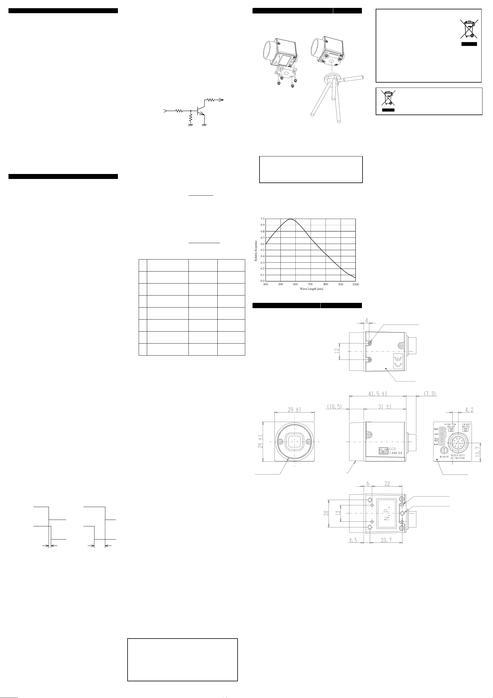
HOW TO FIX CAMERA
(1) Use tripod
If you use tripod, use camera mounting kit (optional) and fix
camera.
(2) Use fixing holes on the bottom of camera
If you use fixing holes on the bottom of camera, Please use
screw (M2 and M3).
Please use screw length less then 3mm.
If the screw is long, it touches with printed circuit board,
and it causes some trouble and accident.
Typical spectral response
[The lens characteristics and light source characteristics is not
reflected in the table.]
CAUTION
DRAWINGS
C mount
Spec
cation
Material Lens-mount, Rear panel : Aluminum die-cast
Cover : Anticorrosion aluminum alloy
Processing Lens-mount, Rear panel : Cation coating
Cover : Leather satin coating
Mount
Following information is only for EU-member states:
The use of the symbol indicates that this
product may not be treated as household
waste. By ensuring this product is disposed
of correctly, you will help prevent potential
negative consequences for the environment
and human health, which could otherwise be caused
by inappropriate waste handling of this product.
For more detailed information about the take-back and
recycling of this product, please contact your supplier
where you purchased the product.
”This symbol is applicable for EU member
states only”
2-M2 depth 3
Cover
Rear panel
4-M2 depth 3
3-M3 depth 3
D3004765A
 Loading...