

Page 1

B/W CCD Camera
Model CS3720
Operation Manual
TOKYO ELECTRONIC INDUSTRY CO., LTD.
2000-08-07
Page 2
BEFORE USE ------ GENERAL SAFETY INSTRUCTIONS
This instruction manual contains important information for the operator(user) and/or
people around him/her to avoid personal injuries, or property damages against him/her
or people around him/her by using this product correctly. Prior to use, read this
operation manual carefully to fully understand its instructions for correct use.
OWNER'S RECORD
Enter the blank below Product Serial Number, which is found on bottom/rear chassis of
your device. Keep. this number for your record.
Serial No.
WARNINGS & CAUTIONS
[Definition of markings]
The meaning of each mark used in this instruction manual is given below.
DANGER
This mark warns the user that improper use, indicated with this mark, may
cause death or severe personal injuries against the user or people around
him/her.
CAUTION
This mark warns the user that improper use, indicated with this mark, may
cause personal injuries (*1) or material damages (*2) against the user or
people around him/her.
Notes
*1 : Personal injuries mean wounds, burns, electric shocks, and others for which the
person injured need not to be hospitalized nor to be cared for the long term.
*2 : Material damages mean any direct or consequential damages related to property or
material loss
[
This mark indicates what the user SHOULD NOT DO. The details of things which the user
should not do are described next to this mark.
Q
This mark indicates what the user MUST DO. The details of things which the user must do
are described next to this mark.
This mark indicates that the user must be alert against a possible DANGER. The details of
the DANGER which the user must be aware of are described next to this mark.
Ì
This mark indicates that the user are given a CAUTION against possible hazards. The
details of the CAUTION which the user must be aware of are described next to this mark.
QHandling Precautions
DANGER
Q
If any overheating sign is observed, discontinue he use immediately.
In the event that smoke, smell, or any other overheating sign is observed, turn the power
switch of the system OFF immediately, and remove the camera cable from the camera
connector. Do NOT try to continue to use the camera. To do so in spite of clear signs of
malfunction invites a fire, an electric shock hazard, or a serious damage to the camera. In
such case, contact us or our dealer/distributor from which you purchased the camera for
repair service.
1
Page 3
Q
If any malfunctioning sign is observed, discontinue the use immediately.
NOT try to use the camera when it is malfunctioning. (Ex. No images on the
monitor) In the event of malfunction, turn the power switch of the system OFF
immediately, and remove the camera cable from the camera connector. In such case,
contact us or our dealer/distributor from which you purchased the camera for repair
service.
Q
If any foreign object / liquid gets into the camera, discontinue the use immediately.
In the event that liquids, small particles, or any other foreign objects get into the camera,
do NOT try to continue to use the camera. To do so invites a fire or an electric shock
hazard. In that case, turn the power switch of the camera OFF immediately, and remove
the camera cable from the camera connector. After that, contact us or our
dealer/distributor from which you purchased the camera for repair service/technical
advice.
[
Do NOT disassemble the camera
Do NOT attempt to pull apart, repair, or modify the camera on your own. To do so leads
to a fire or an electric shock accident. Contact us or the dealer/distributor from which
you purchased the camera for repair/modification.
[
Do NOT supply any power other than specified.
The camera is designed to work only under specified voltage. Do NOT attempt to drive
the camera with the power other than specified. Operating the camera under unspecified
power invites a fire or an electric shock hazard.
[
Do NOT use the camera in a high-humidity environment.
Do NOT place the camera near a humidifier, or in other high-humidity environment.
To do so may cause a fire or an electric shock accident.
CAUTION
If the camera is operated in the electromagnetic field, there may be cases where beat
noises (vertical, horizontal, or oblique stripes) may appear in the video output. In that
case, take preventive measures on the electromagnetic-wave generating source so that
the camera do not receive the interference by the electromagnetic-wave. Take extra
precautions against electromagnetic-wave-interference if the camera is used with a
servomotor, inverter, or other electromagnetic-wave-generating equipment.
Avoid giving a strong shock against the camera. If your camera is used in the system
where its camera connector is subjected to strong repetitive shocks, the camera
connector is possible to break down. If you intend to use your camera in such a situation,
make sure to use an optional camera-connector-fixing-hardware to connect the
connector-plug to the camera body.
When the camera is not in use, make sure that a lens or lens-cap is put on so that the
image pickup plane of CCD is protected from dust, foreign object, or other flaw-causing
object. If the glass plane (image pickup plane) gets dirty, clean it with a cotton swab.
When it needs to be cleaned with a cleaner, be sure NOT to use any organic solvent other
than ethyl alcohol. As a countermeasure against condensation, when the camera is
moved from a warm place to a cold place, take appropriate precautions to prevent
condensation from forming on the camera.
Do not pull strongly the camera cable nor swing it. The stress from pulling or swinging
may cause damage in the coating of the cable, or breaks in the inside wires.
2
Page 4

Avoid shoat-circuiting its signal output. Otherwise, the camera might be damaged.
If too much amount of light, (= the incoming light amount of 100 times or greater in
comparison with standard light) enters CCD image pickup plane, video output might not
be obtained. In such a case, take measures to reduce the amount of incoming light.
Do NOT expose the camera to intensive light (sunlight, etc.) to prevent its inner CCD
from getting damaged.
When mounting a lens, take extra caution so that the lens is not tilted, nor does flaw exist
at the lens-mount-screw part. Also check to confirm that no dirt nor other foreign object
is put inside. Improper mounting might cause the parts to become locked.
Do NOT connect/disconnect connectors with power ON.
Before connecting/disconnecting connectors, make sure to check if the system. is
powered OFF. Doing so with power ON may cause a damage or an electric shock
accident.
DANGER
[
Do NOT use any optional unit other than manufacturer-supplied one. [We disclaim any
responsibility for damages or losses incurred by user due to the use of unauthorized /
unofficial option units supplied by a third-party]
RESTRICTION FOR USE
In case malfunction of this equipment (e.g. video output cut-off) can be expected to lead
to significant accident, avoid using this equipment for such system integration use.
CASES FOR INDEMINITY (LIMITED WARRANTY)
We shall be exempted from taking responsibility and held harmless for damages or
losses incurred by user in the following cases.
1. In case damages or losses are caused by fire, earthquake, or other acts of Gods, the
act by third party, misuse by the user deliberately or erroneously, use under extreme
operating conditions.
2. In case indirect, additional, consequential damages (loss of expected interest,
suspension of business activities) are incurred as results of malfunction or nonfunction of the equipment, we shall be exempted from assuming responsibility for
such damage.
3. In case damages or losses are caused by incorrect use which is not in line with the
instructions in this instruction manual.
4. In case damages or losses are caused by malfunction resulting from bad connection
with other equipment.
5. In case damages or losses are caused by repair or modification done by the user.
3
Page 5

IMPORTANT SAFETY INSTRUCTIONS
(1) Use DC12V power. Avoid using any other unspecified power source.
(2) This device is designed and guaranteed to work under the temperature range of 0
through 40 degree C. Avoid using the equipment beyond that limits.
(3) Do NOT expose the camera’s image-pickup-plane to sunlight or other intense light
directly. Its inner CCD (charge-coupled device) might be damaged.
(4) When your camera is not in use, make sure a lens or lens-cap is on the camera-head
so that the image pickup plane of CCD is protected from dust, foreign object, or
other flaw-causing object.
(5) Handle your camera with care. Do NOT drop nor give a strong shock to avoid
breakdown.
(6) In the event that any abnormal condition is observed, turn the power switch OFF
immediately. Do NOT try to continue to use the camera. To do so in spite of clear
signs of malfunction invites a fire, an electric shock hazard, or any other serious
damage to the camera. In such case, contact us or our dealer/distributor from which
you purchased the camera for repair service.
(7) To clean the body of this equipment, make sure to turn the power switch OFF first.
To remove stubborn stains, use a soft cloth soaked in diluted acid-free detergent.
After that, clean with a dry cloth.
(8) In case the image-pickup-plane should be settled with fine dust, dirt, or scratched,
ask our distributor for technical advice.
CONTENTS
1. PRODUCT DESCRIPTION
2. FEATURES
3. CONFIGURATION
4. OPTION UNIT
5. FUNCTION / LOCATION OF SWITCHES AND OTHERS
6. OPERATION MODE
7. CONNECTOR CONNECTION
8. SPECIFICATIONS
9. TIMING CHART
10. EXTERNAL VIEW
4
Page 6

1. PRODUCT DESCRIPTION
Model CS3720 is a separated-type (two-body) B/W CCD camera with all-pixel-data
readout CCD. This model has twice greater driving frequency of CS3710 to achieve
fast-speed data-processing. The model is suited for high-speed, high-resolution image
processing use.
2. FEATURES
(1) Double-speed scan
This model reads out image-data twice as fast as conventional cameras do.
(2) All pixel’s data readout
With its built-in all-pixel-data-readout CCD, this model can read out image-data just in
approximately 1/120 sec. A frame-shutter reads out all data even under RTS mode.
(3) Random trigger shutter function
With a built-in RTS (Random Trigger Shutter), the camera’s CCD starts light-exposure
in synchronization with external trigger signals. This function enables the camera to
capture fast-moving subjects at constant position for precise image processing.
(4) Programmable partial scan
Readout portion of pixels is determined by external pulse. As only needed portion is
read out, further speed-up in data-readout & processing is achieved.
(5) High vertical resolution
As all pixel’s data are read out even under RTS mode (in 1/120 sec.), images with no
deterioration in vertical resolution are obtained.
(6) Square grid pattern CCD
Pixel’s in CCD ace aligned in square grid pattern. This makes it easier to perform
computation correctly for image processing use.
(7) External Sync.
The camera is switched over to external synchronization operation automatically when
external HD/VD signal is input.
(8) Multiple shutter
With this function, the camera can capture video at any given timing, then outputs
video images at a set timing.
(9) Ultra-compact & light-weight camera head
The model features its ultra-compact and light-weight camera head, freeing you from
your integration-space-problem. In addition, it has an excellent shock & vibration
resistance.
5
Page 7
3. CONFIGURATION
(1) Camera head (With a 3.0m directly-fixed camera-cable) 1
(2) Camera Control Unit 1
(3) Accessory
Operation Manual 1
4. OPTION UNIT
(1) DC SYNC IN cable (Model name: CPRC3700) 1
(2) Camera adapter (Model name: CA170) 1
(3) Camera mounting kit 1
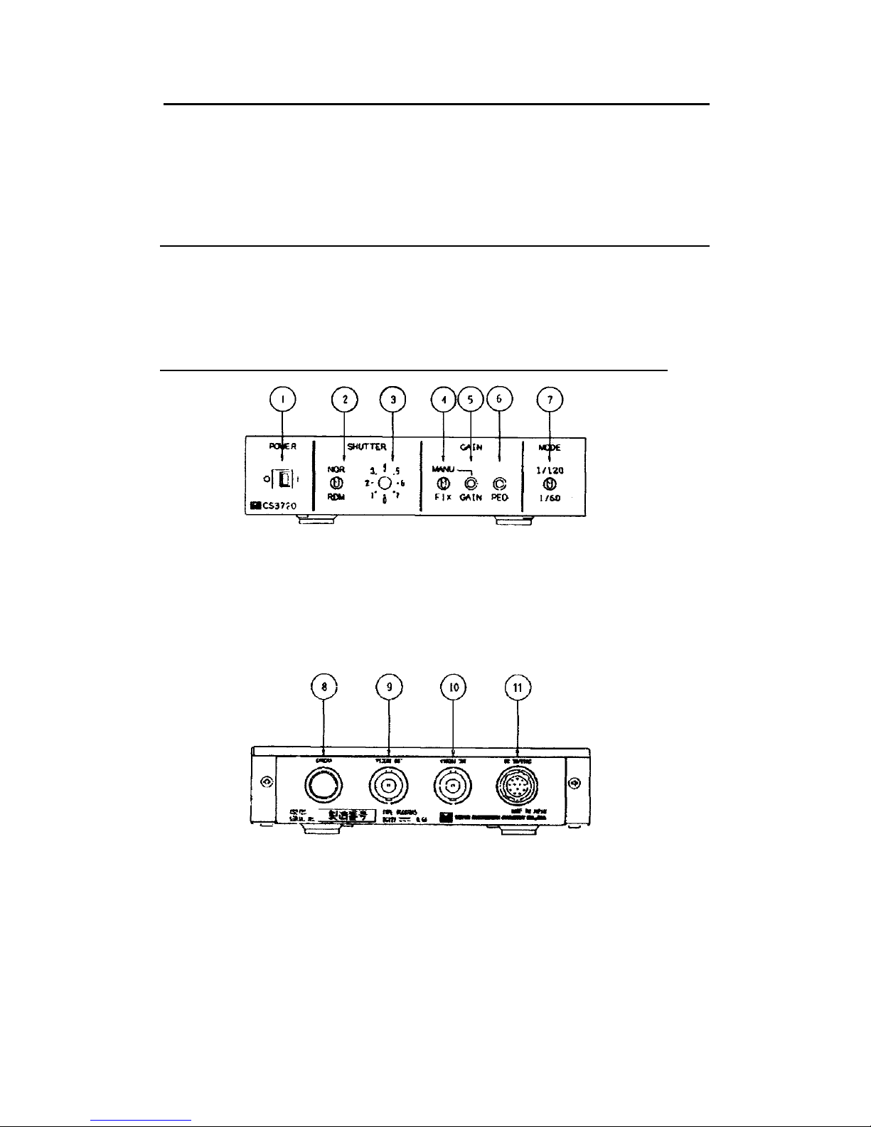
5. FUNCTION / LOCATION OF SWITCHES AND OTHERS
1: POWER Power ON / OFF selection SW
2: SHUTTER. (M) Shutter mode selection SW
3: SHUTTER. (S) Shutter-speed selection rotary SW
4: GAIN CONT Gain control selection SW
5: GAIN Gain control potentiometer under manual setting mode
6: PED Pedestal (black) level control potentiometer
7: MODE Video output mode selection SW
8: CAMERA Camera connector
9: VIDEO 1 OUT Video output connector
10:VIDEO 2 OUT Video output connector
11: DC IN / SYNC External-sync connector
6
Page 8
6. OPERATION MODE
(1)GAIN selection (CCU front-panel SW)
MANU: Gain is adjustable via the manual gain potentiometer (GAIN)
FIX: Factory-prefixed gain
(2)Video output mode selection (CCU front-panel SW)
1/120: 1/120s----- 2:1 interlace mode (Dual-line output)
1/60: 1/60s----- Non-interlace mode (Single-line output)
(3)Shutter mode selection (CCU front-panel SW)
NOR mode: Normal electronic shutter
----- High-speed shutter: From 1/20,000s through OFF (8 position)
RDM mode: Random trigger shutter
----- FIX: High-speed shutter: From 1/20,000s through OFF (8 position)
----- PULSE: Exposure-time control via ex-trigger signal pulse width
(4)Shutter-speed selection (Exposure time)
FIX: Shutter-speed control under NOR or RDM .mode (FIX: Inner SW 1-1 OFF)
(Rotary SW setting)
Position Shutter speed
0 OFF (Factory-shipped)
1 1/250s
2 1/500s
3 1/1000s
4 1/2000s
5 1/4000s
6 1/8000s
7 1/20000s
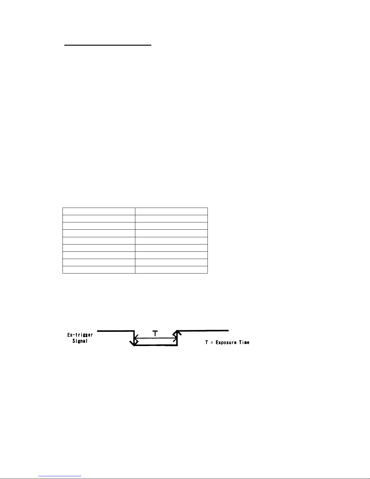
PULSE: Shutter-speed control under RDM mode (FIX: Inner SW 1-1 ON)
In this mode, the shutter-speed is controlled by the pulse width of external trigger
signal. Use this mode when you need wider, user-defined shutter-speed.
Exposure starts at the falling edge of the external trigger signal.
Exposure ends at the rising edge of the external trigger signal.
7
Page 9
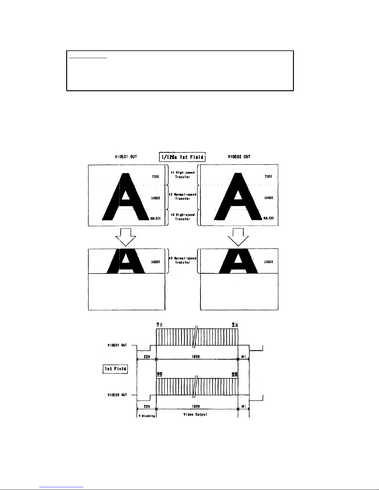
(5)Partial-scan mode selection
IMPORTANT
Sometimes, white blooming is observed at the upper side of the screen when intensive
light enters the image-pickup-area in a wide angle. This phenomenon is not attributable
to malfunction of the camera. If the white blooming occurs, try and reduce the amount
of incoming light.
(5-1)1/2 PARTIAL: Screen half-center readout mode (Inner SW 1-2 ON, SW 1-3 OFF)
Under 1/120 interlace, the screen-center 204H is readout out of effective 485H lines (=
excluding BLK lines). This works both under internal and external sync operation.
*1 Under ex-sync, user-defined value.
8
Page 10

*1 Under ex-sync, user-defined value.
9
Page 11
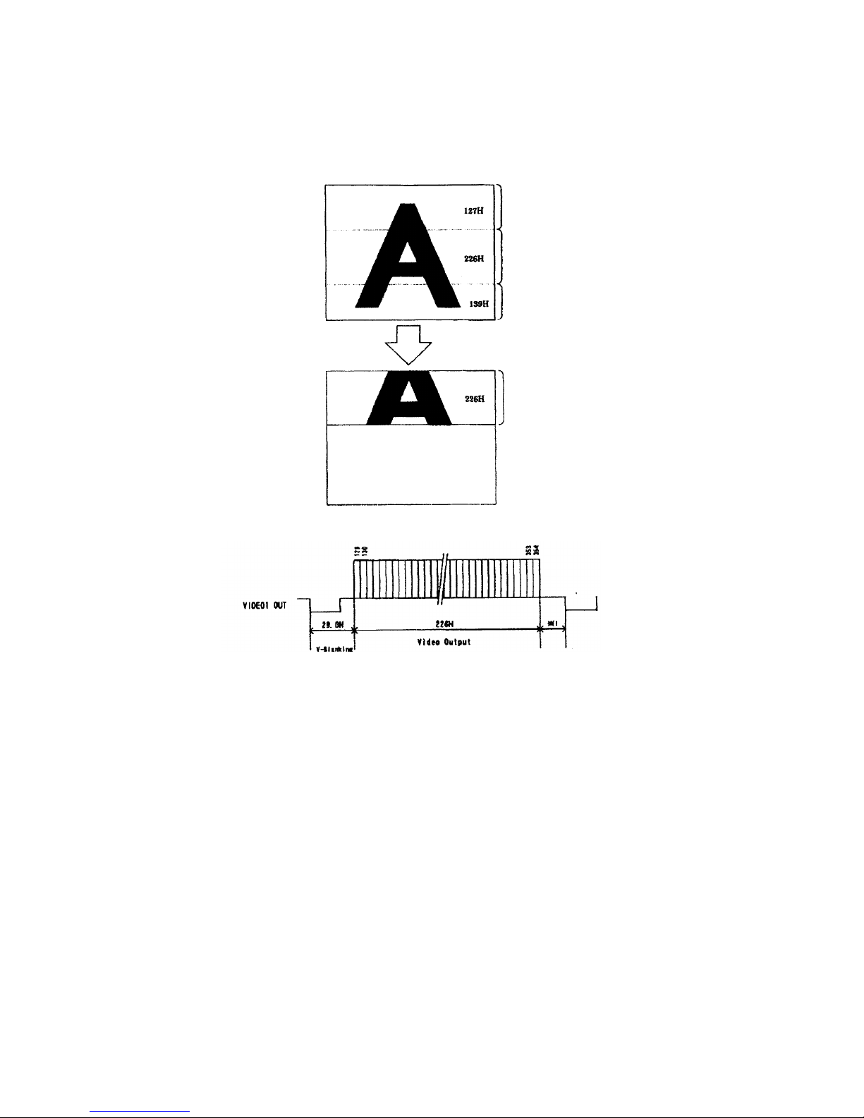
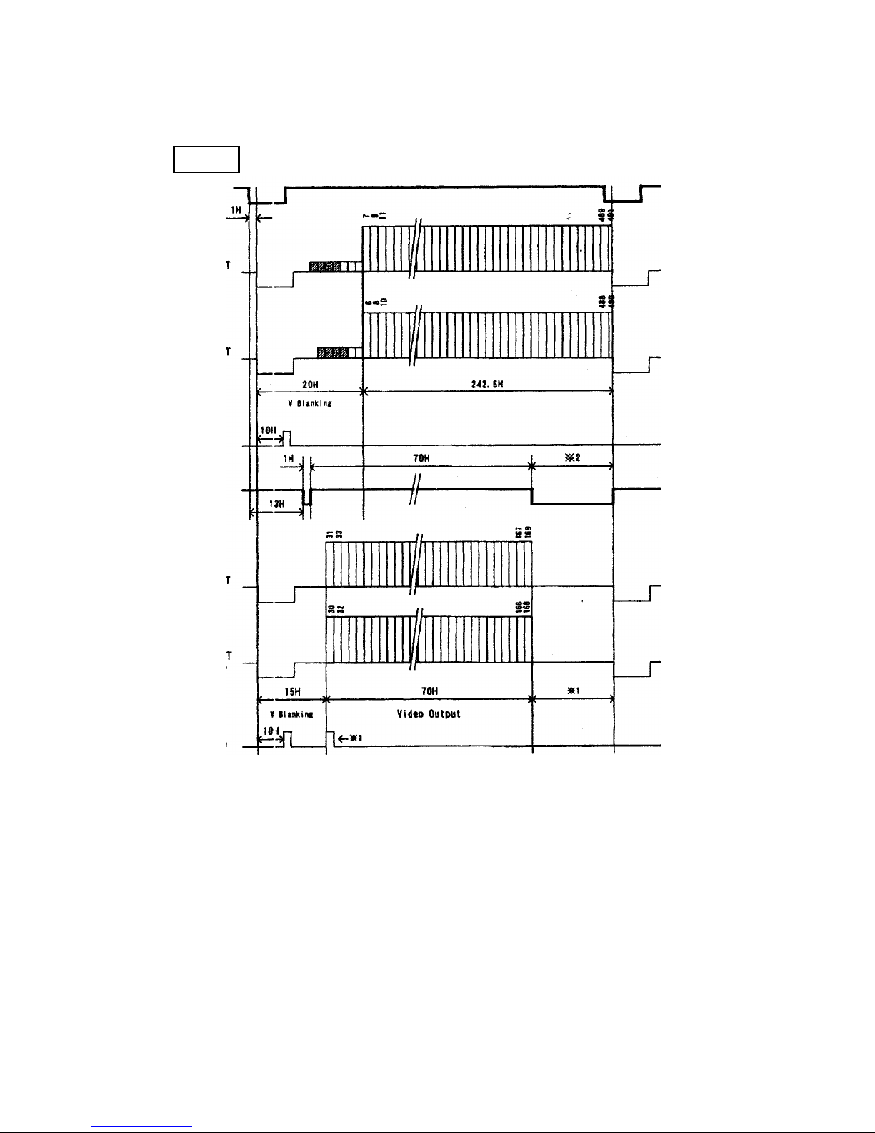
Under 1/60 non-interlace, the screen-center 226H is readout out of effective 492H lines (=
excluding BLK lines). This works both under internal and external sync operation.
1/60s Non-interlace
*1 High-speed
Transfer
*2 Normal-speed
Transfer
*3 High-speed
Transfer
*2 Normal-speed
Transfe
r
*1: Under ex-sync user-defined value.
10
Page 12
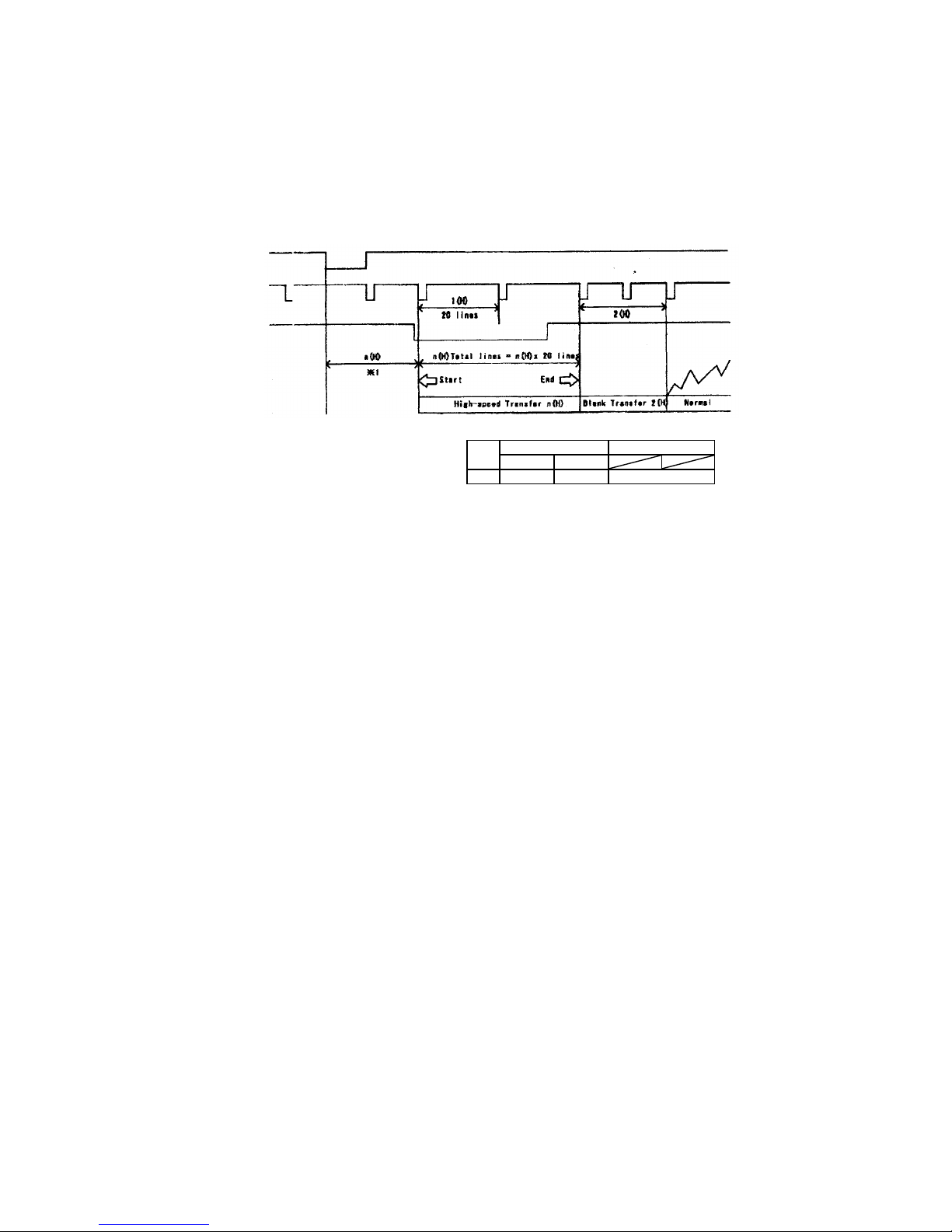
(5-2) PROGRAMMABLE: Readout portion programmable mode
(Inner SW 1-2 OPT, SW 1-3 ON)
In this mode, the readout portion is programmable via external pulse. High-speed transfer
segment is set with partial pulse input. This works under external synchronization only. An
example is shown below.
EXT. VD
FIT. HD
PARTIAL PULSE
VIDEO OUT
■ The starting point of partial pulse is at the falling edge of external VD. (Length: * 1)
■ Partial pulse timing is controlled by EXT HD (at the falling edge). Set partial pulse
start point and end point with interval longer than 1H
■ The high-speed line counts during 1H are 20 lines.
■ After the high-speed transfer, 2H is allocated for blank transfer, immediately followed by
normal transfer segment.
11
1/120s interlace 1/60s non-interlace
*1
1st field 2nd field
a(H) 13.0 12.5 21.0
Page 13
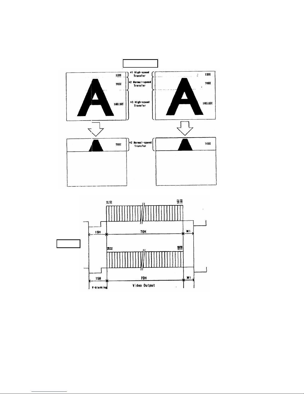
Example: Readout portion --- Upper part of image
(Upper part of “A”, 70H, out of total effective pixel 485H)
12
VIDEO1 OUT
1st Field
VIDEO2 OUT
VIDEO1 OUT
1/120s 1st Field VIDEO2 OUT
*1: Under ex-s
ync,
user-defined value
Page 14
PARTIAL PULSE Input Example
1st Field
EXT. VD
VIDEO1 OUT
(Normal)
VIDEO2 OUT
(Normal)
WEN OUT
(Normal)
Partial
Pulse
VIDEO1 OUT
VIDEO2 OUT
(Partial)
WEN OUT
(Partial)
*1 Under ex-sync, user-defined value.
*2 “Over-partial” (=More than actual video lines) is OK.
*3 Under partial-scan, WEN is output twice. The second output
syncs with the first line (1H) of video output.
13
Page 15
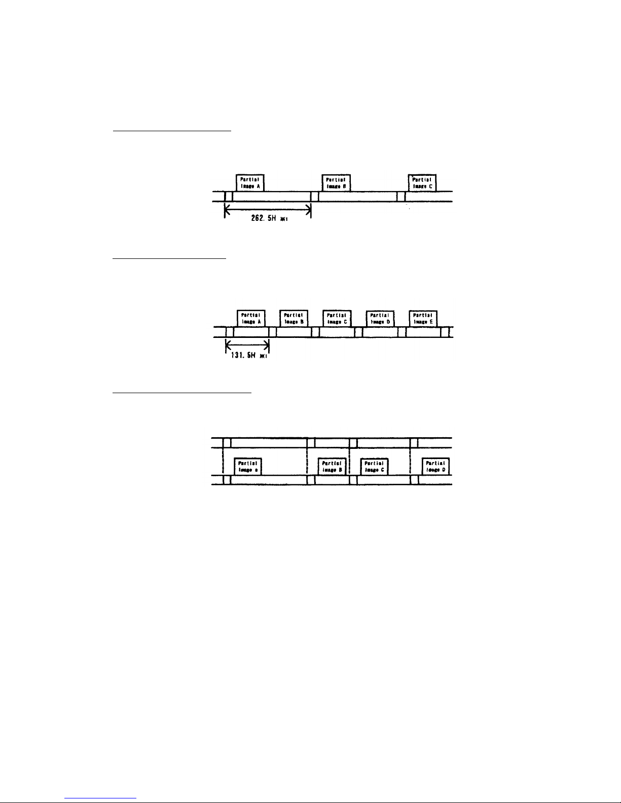
(5-3) Reset: Sync-signal reset under partial-scan (Inner SW 1-4 ON)
When the inner V-reset switch (SW 1-4) is set in ON position, VD signal will be reset
immediately after image readout. This SW is enabled under 1/2 partial-scan mode only,
and works under internal sync operation mode.
V-reset OFF (Internal-sync)
VD signal: Normal 262.5H
VIDEO OUT
*1 Under 1/60 noninterlace mode 262
K
V-reset ON (Internal-sync)
VD signal will be reset immediately after image readout.
Twice faster readout is obtained in comparison with the V-reset OFF mode.
VIDEO OUT
V-reset ON/OFF (External-sync)
Regardless of the V-reset ON/OFF, video output will be in sync with the external input,
EXT VT) signal
EXT. VD
VIDEO OUT
14
*1 Under 1/60 noninterlace mode 525H
Page 16
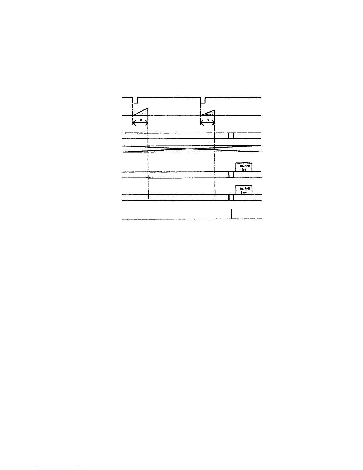
(6)Multiple-shutter mode (Works under RTS mode)
Under the random trigger shutter mode, consecutive trigger signals give cue for starting
CCD exposure, arid image is output at user-defined timing. You can use this shutter
mode under external synchronization operation (E.HD, E.VD) only. The video output
timing is determined by E.VD. No inner SW setting is necessary. The multiple shutter
functions under all RTS mode.
15
TRIG
CCD Exposure
EXD. VD
EXD. HD
VIDEO1 OUT
VIDEO2 OUT
WEN OUT
Page 17
(7)Camera control unit inner SW setting (Factory-shipped setting)
IMPORTANT
To avoid shock hazard, follow the instructions given below.
■ Turn the power of your system OFF first.
■ Remove all connection cables.
■ For making inner SW setting, use an appropriate device available on market.
■ Do NEVER dismount circuit boards.
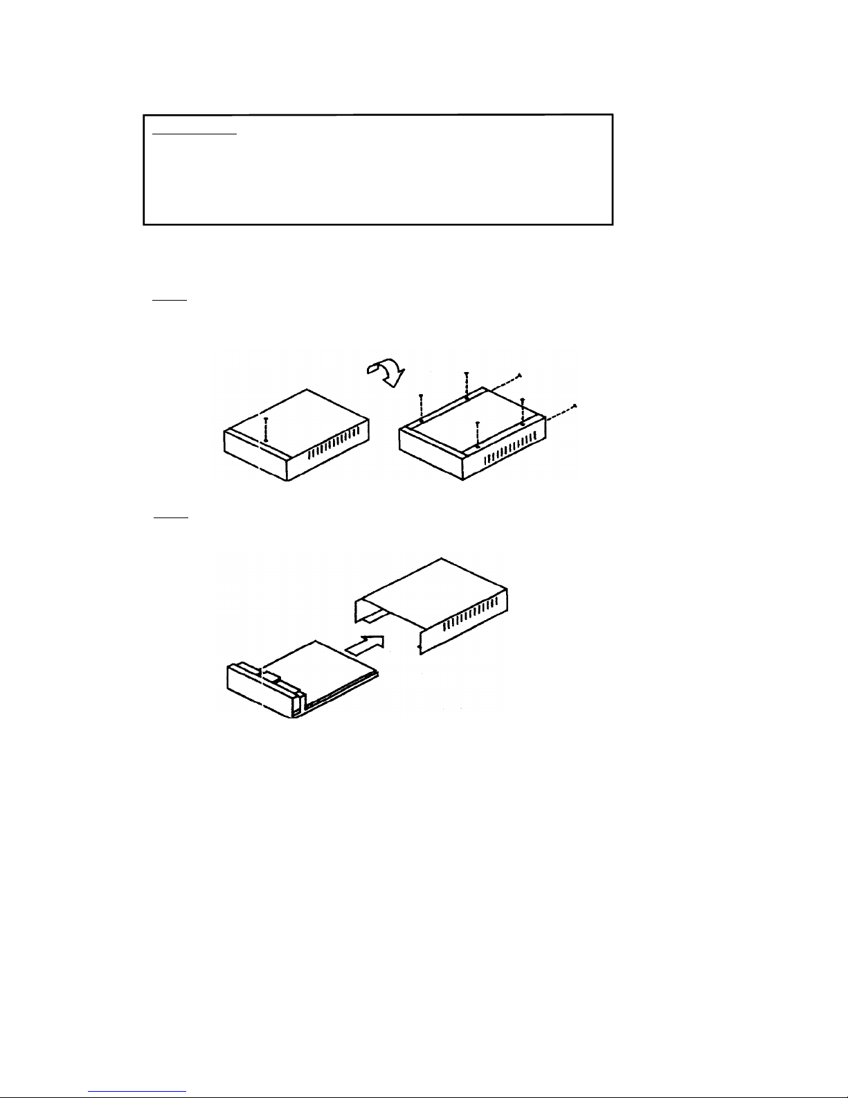
(7-1) How to remove the cover.
Step 1
Unscrew fastening; screws located at the bottom of camera control unit, and on the rear panel
(7 p
laces).
Step 2
Draw the cover out in the followin
g
direction.
To reattach the cover, follow the above steps in the reverse order.
Page 18
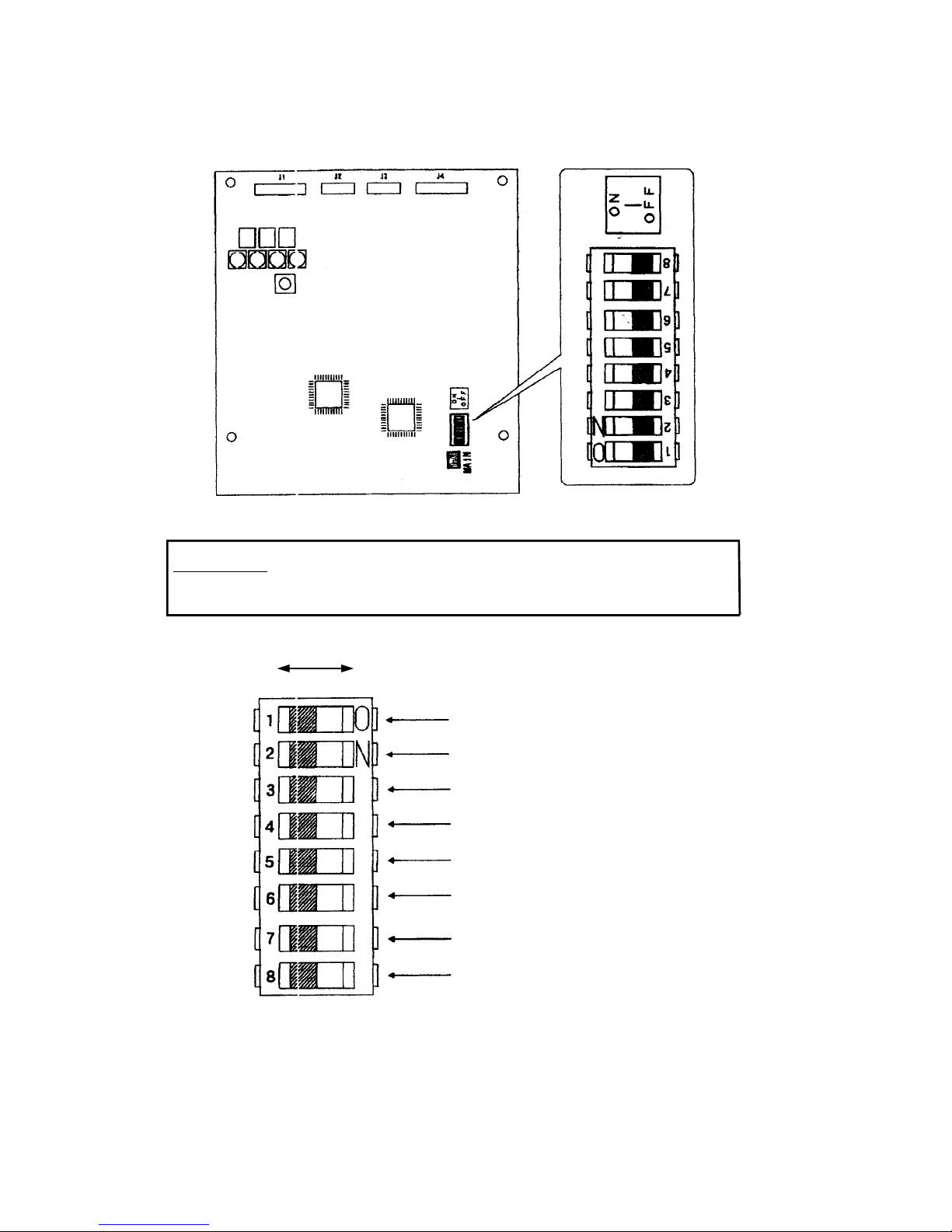
(7-2) Inner SW board layout
Rear side
Front side
IMPORTANT
All switches other than SW1 is factory-preset. Don’t touch any factory-preset switches.
(7-3) Inner SW assignment
OFF ON
SHUTTER (FIX/PULSE)
PARTIAL (ON/OFF)
PARTIAL
(1/2 Partial/Programmable)
PARTIAL V RESET (ON/OFF)
TRIG (NEGA/POS1)
NC (OFF Fixed)
TEST1 (For factory-check)
TEST2
(
For factory-check)
Inner SW (SW1)
[Factory-setting]
17
Page 19
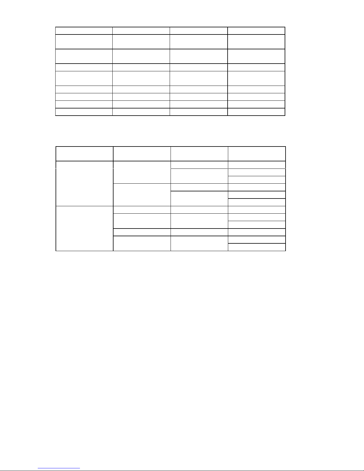
SW Number Function OFF ON
1 Shutter-speed FIX
(Electronic shutter)
PULSE
(TRIG width)
2 Partial-scan
ON/OFF
Normal scan Partial-scan
3 Partial-scan 1/2 Partial Programmable
4 Partial-scan
V reset
Non-reset V reset
5 TRIG polarity Negative Positive
6 NC OFF Fixed ----7 TEST 1 OFF Fixed ----8 TEST 2 OFF Fixed -----
*Notes: Under external synchronization mode, all shutter modes are acceptable.
18
Video Output Mode
[Front Panel SW]
Shutter Mode
[Front Panel SW]
Readout Mode
[Inner SW1-2]
Partial Setting
[Inner SW1-3]
Normal scan -----
1/2 Partial
Normal
Partial scan
Programmable
Normal scan -----
1/2 Partial
1/120 Interlace
Random
Partial scan
Programmable
Normal Normal scan -----
1/2 PartialPartial scan
Programmable
Random Normal scan -----
1/2 Partial
1/60 Non-interlace
Partial scan
Programmable
(7-4) Shutter-mode
Page 20
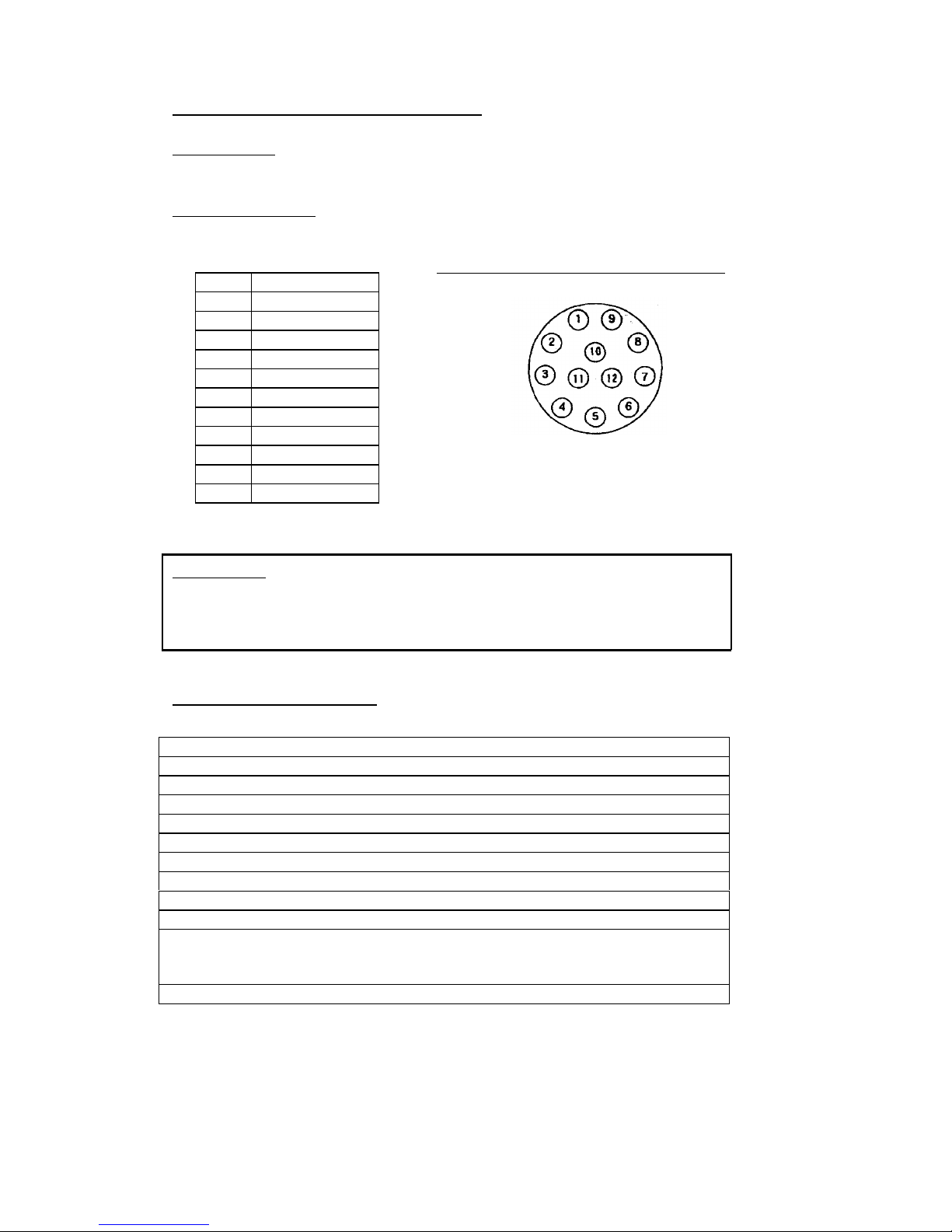
7. CONNECTOR CONNECTION
Connector used:
DC/SYNC connector --- HR10A-12R-12PB Manufactured by HIROSE DENKI
Compatible connector:
DC/SYNC connector --- HR10A-12P-12S Manufactured by HIROSE DENKI
Picture: DC IN/SYNC connector
(
Rear-view)
IMPORTANT
If you plan to use video output from DC IN / SYNC connector (12 pin connector), do
NOT use BNC connector outputs (2 places). If both are used at the same time, you will
not obtain correct video signal due to double termination.
8. SPECIFICATIONS
Model CS3720
Image sensor All Pixel’s Data Read-out Interline CCD
Optical size 1/2 Type (= Equivalent to 1/2” image pickup tube)
Active pixel 659(H) x 494(V)
Unit cell size 9.9(H) x 9.9(V) micro m (Square-grid array)
Scanning area 6.4(H) x 4.8 mm
Scanning lines 525 lines
Interlace 1/120s 2:1 Interlace mode
1/60s Non -interlace mode
Sync system Internal/External automatic switch-over
Scanning frequency 31.468kHz(H)
119.88Hz(V) (1/120s 2:1 Interlace mode) or
59.94Hz(V) (1/60s Non-interlace mode)
Aspect ratio 4:3
1 GND
2 +12V
3 VIDEO.GND
4 VIDEO 1 OUT
5 HD/VD.GND
6 HD.IN
7 VD.IN
8 GND
9 VIDEO 2 OUT
10 WEN OUT
11 TRIG IN
12 PARTIAL IN
Page 21

Illumination Standard 400 lx (F5.6) (1/60s Non-interlace mode, GAIN FIX)
Minimum 4 lx (F1.4) (GAIN MAX)
Gain MANU / FIX Switch-able through front-panel selection MANU
(Manual) gain: Setting through GAIN VR
FIX (Fixed) gain: Factory-shipped preset level
Video output VS 1.0V (p-p) / 75-ohm
Resolution 485 lines(H) (Under 1/60s Non-interlace)
350 TV lines(V) (Under 1/120s 2:1 Interlace)
S/N Standard: 50dB(p-p)/rms (GAIN FIX)
Input signal
(1)Ex-sync. signal HD/VD
Input level HD/VD: 5V(p-p)/10k-ohm
Pulse width HD: 3.2 plus/minus 1 micro s (Negative)
VD: From 125 through 400 micro s (Negative)
Frequency variation 31.468kHz plus/minus 1 percent
Phase difference HD/VD: 0 plus/minus 2.5 micro s, 1/FH/2 plus/minus 2.5 micro s
(2)Shutter trigger IN Expsure-starting-cue signal in random trigger shutter mode
Input level TRIG: 5V(p-p)/10k-ohm
Pulse width Longer than 5 micro S (Negative)
(3)Partial High-speed transfer signal under partial-scan mode
Input level PARTIAL: 5V(p-p)/10k-ohm
Pulse width Setting available in 1H increments (Negative)
Output signal
(1)WEN CCD readout timing pulse in random trigger shutter mode
Output level WEN: Over 4V(p-p)/ 50-ohm
Pulse width 1H (Positive)
Electronic shutter
Normal shutter From 1/20000 through OFF, 8 scales
RTS (FIX) From 1/20000 through OFF, 8 scales
RTS (PULSE) TRIG signal pulse width control
Gamma correction Gamma =1 (Fixed)
Power source
Power capacity DC12V plus/minus 10 percent
Current capacity 0.9A and over
Ripple voltage 50mV(p-p) and over
Power connector DC/SYNC IN connector (HR10A-10P-12S)(HIROSE-DENKI)
Power consumption Approx. 5.0W
Ambient condition Performance guaranteed:
Temperature: From 0 through 40 degree C
Humidity: From 30 through 90 percent (No condensing)
Operation guaranteed:
Temperature: From 0 through 50 degree C
Humidity: From 30 through 90 percent (No condensing)
Lens mount C mount
External dimension Refer to the attached ex-view drawing
Weight Camera-head: Approx. 65g, CCU: Approx. 700g
Page 22
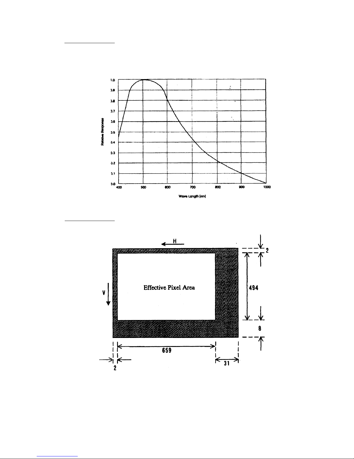
Spectrum Response
(Lens characteristics is reflected in the graph below, while the characteristics of light source is not.)
Optical Black Pattern
21
Page 23
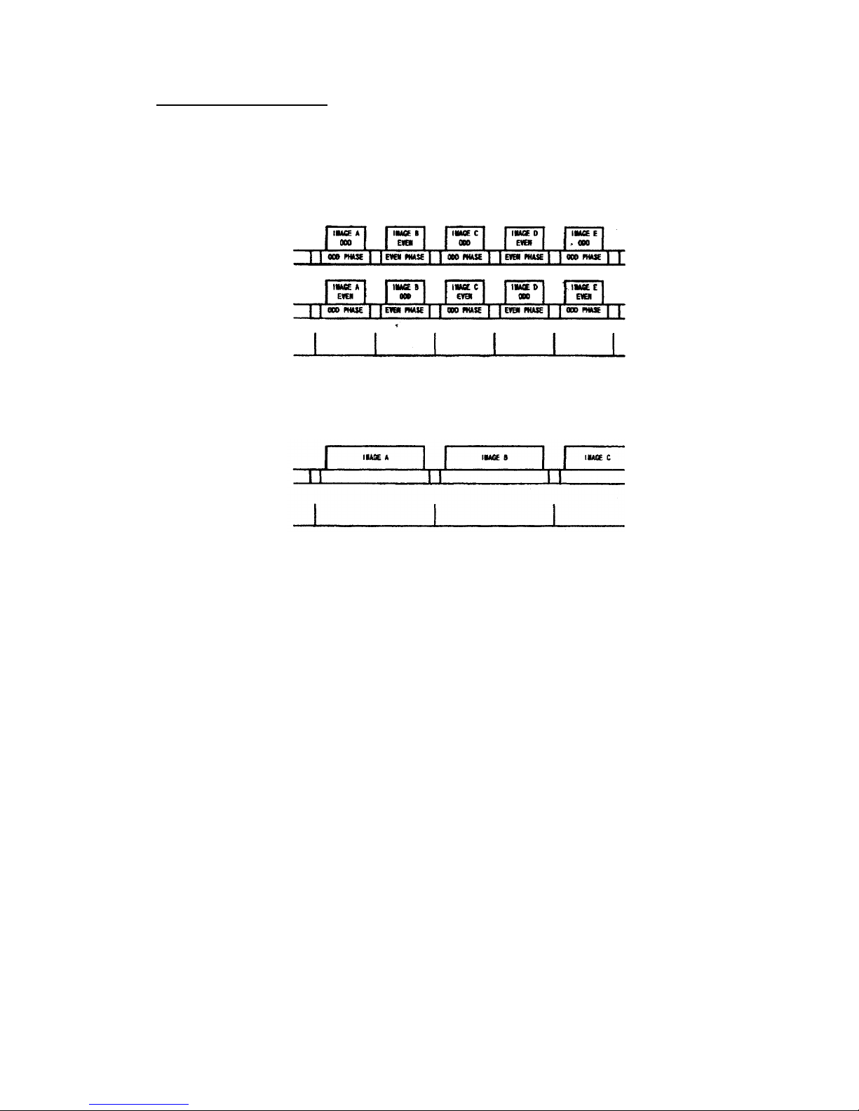
9. TIMING CHART
(1)1/120s 2:1 Interlace mode
Odd Field’s images and Even Field’s images are output in alternating sequence through
both Video 1 and Video 2 terminal in 1/120s, with odd Field’s image through one
terminal, and even Field’s image through the other terminal at the same timing.
VIDEO1 OUT
VIDEO2 OUT
WEN OUT
(2)1/60s Non-interlace mode
1/60s Non-interlace signals are output through only Video 1 terminal.
VIDEO1 OUT
WEN OUT
22
Page 24
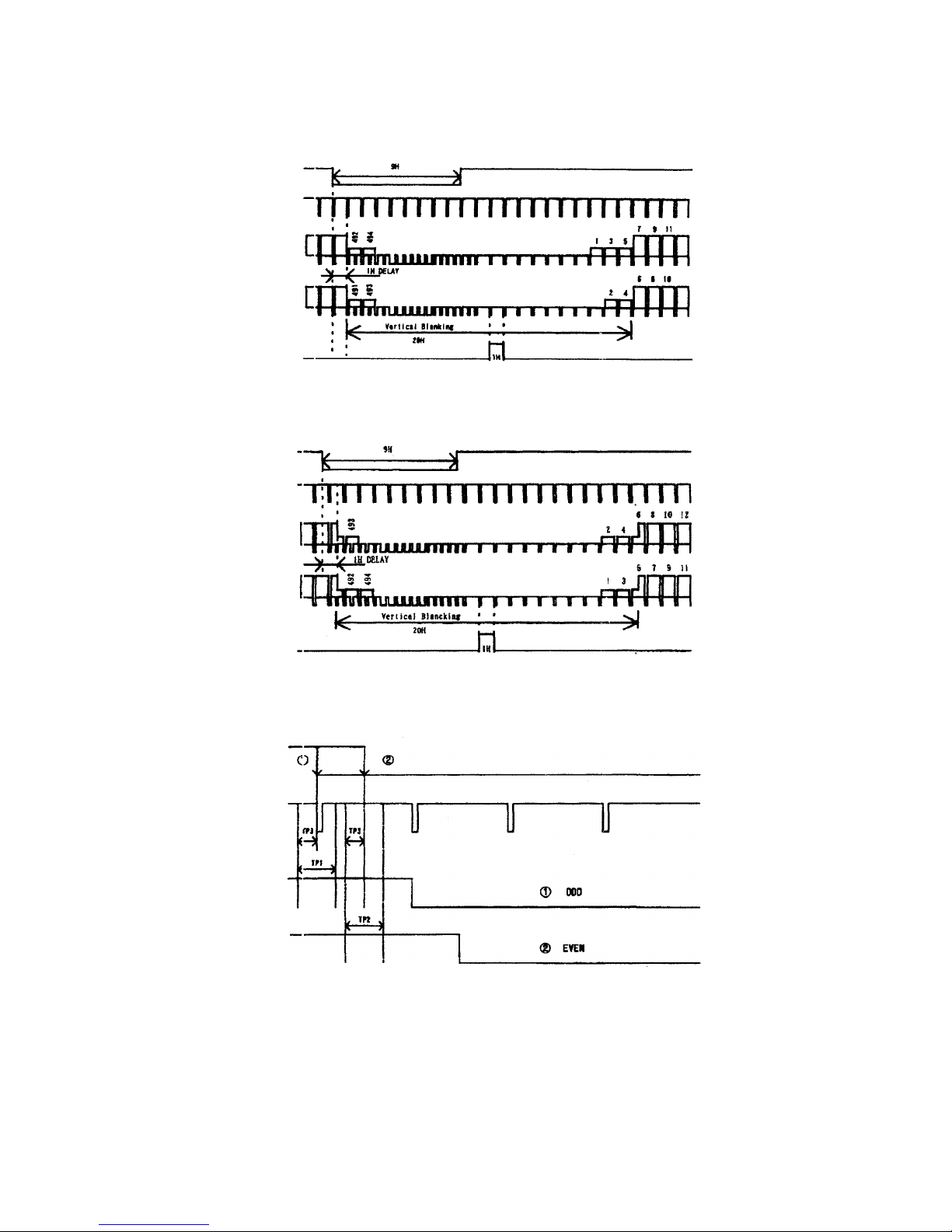
(3)External-sync, 1/120s Interlace mode, Odd phase (1
s
t
Field)
(4)External-sync, 1/120s Interlace mode, Even phase (2
n
d
Field)
EXT. VD
EXT. HD
VIDEO1 OUT
VIDEO2 OUT
WEN OUT
(5)External-sync, 1/120s Interlace mode, Field identification
(HD-VD Phase-difference)
E. VD
EHD
VDO
VDO
TP 1: ODD RESET RANCE 3. 0 µ s
TP 2: EVEN RESET RANCE 3. 0 µs
TP 3: 1.5 µs
23
EXT. VD
EXT. HD
VIDEO1 OUT
VIDEO2 OUT
WEN OUT
Page 25
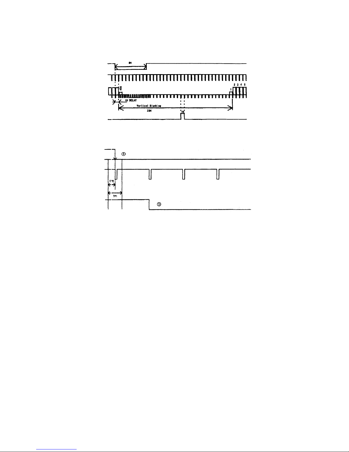
(6)
External-sync, 1/60s Non-interlace mode
(7)
External-sync, 1/60s Non-interlace mode, HD-VD Phase-difference
EXT. VD
EXT. NO
VDO
TP1:6.0µs
TP2
EXT. VD
EXT. HD
VIDEO1 OUT
WEN OUT
Page 26
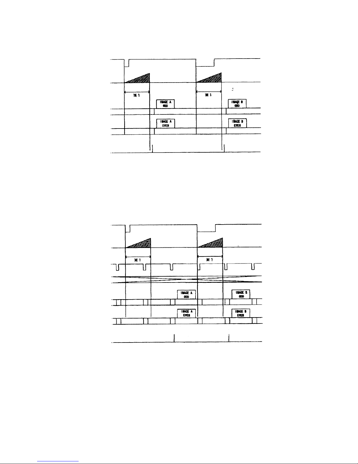
(8)Random trigger shutter, FIX Mode (Internal-sync operation)
TRIG
CCD
(Exp
osure;
VIDEO1 OUT
VIDEO2 OUT
WEN OUT
*1: Setting through the CCU front rotary switch.
You can set the shutter-speed with the CCU front panel rotary switch.
After CCD exposure, VD gets reset in sync with HD to output video signal. Under 1/60s
non-interlace, VIDEO 1 OUT only outputs signal.
(9)Random trigger shutter, FIX Mode (External-sync operation)
TRIG
CCD
(Exposure)
EXT. VD
EXT. HD
VIDEO1 OUT
VIDEO2 OUT
WEN OUT
*1: Setting through the CCU front rotary switch.
You can set the shutter-speed with the CCU front panel rotary switch.
After CCD exposure, video signal is output in sync with the next EXT.VD. Under 1/60s
non-interlace, VIDEO 1 OUT only outputs signal.
25
Page 27
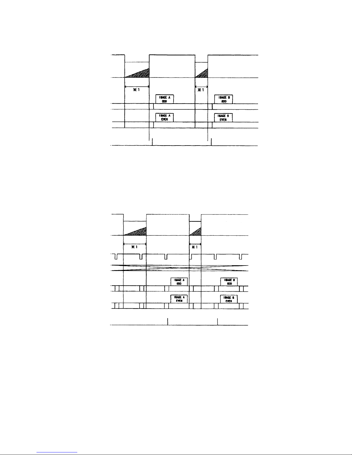
(10)Random trigger shutter, PULSE Mode (Internal-sync operation)
TRI
G
CCD
(Exp
osure
)
VIDEO1 OUT
VIDEO2 OUT
WEN
*1: Determined by TRIG pulse width
The shutter-speed is determined by the length of trigger pulse. After CCD exposure, VD
gets reset in sync with HD to output video signal. Under 1/60s non-interlace, VIDEO 1
OUT only outputs signal.
(11)Random trigger shutter, PULSE Mode (External-sync operation)
TRIG
CCD
(Exposure)
EXT. VD
EXT. HD
VIDEO1 OUT
VIDEO2 OUT
WEN
*1: Determined by TRIG pulse width
The shutter-speed is determined by the length of trigger pulse.
After CCD exposure, video signal is output in sync with the next EXT.VD. Under 1/60s
non-interlace, VIDEO 1 OUT only outputs signal.
26
Page 28
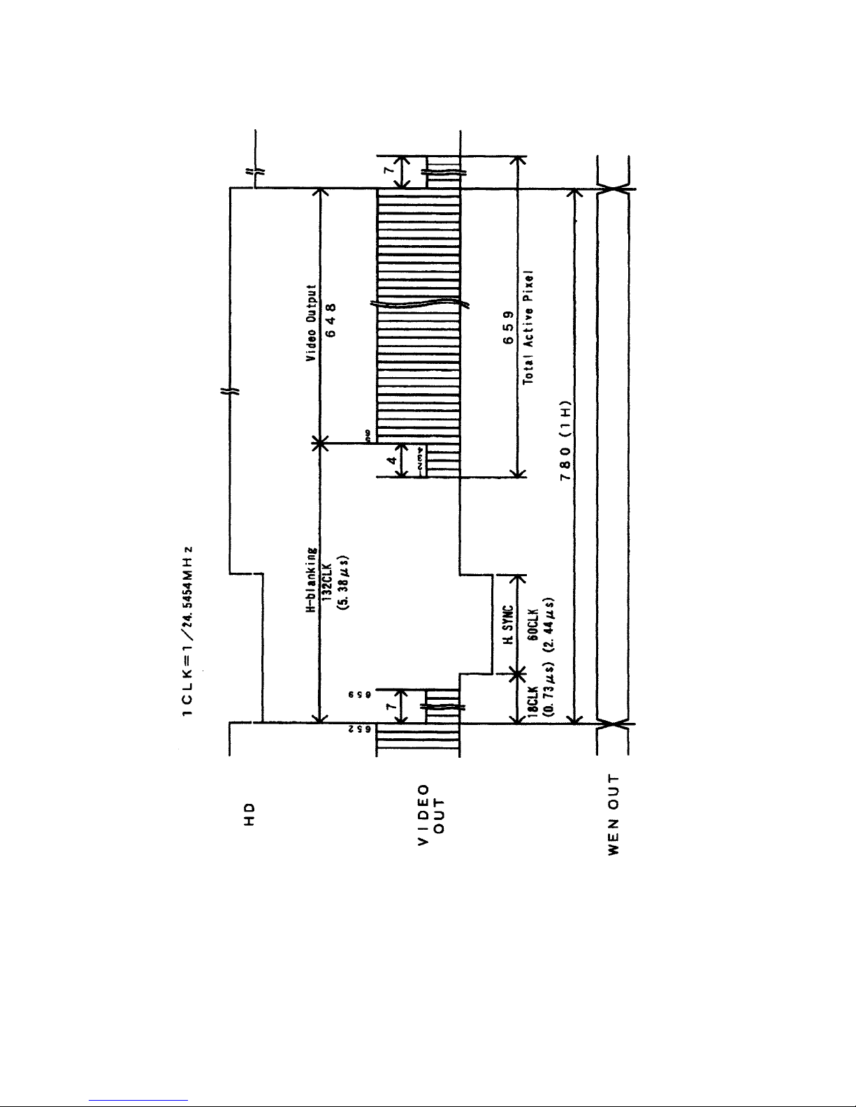
(12)
H-rate timin
g
27
Page 29
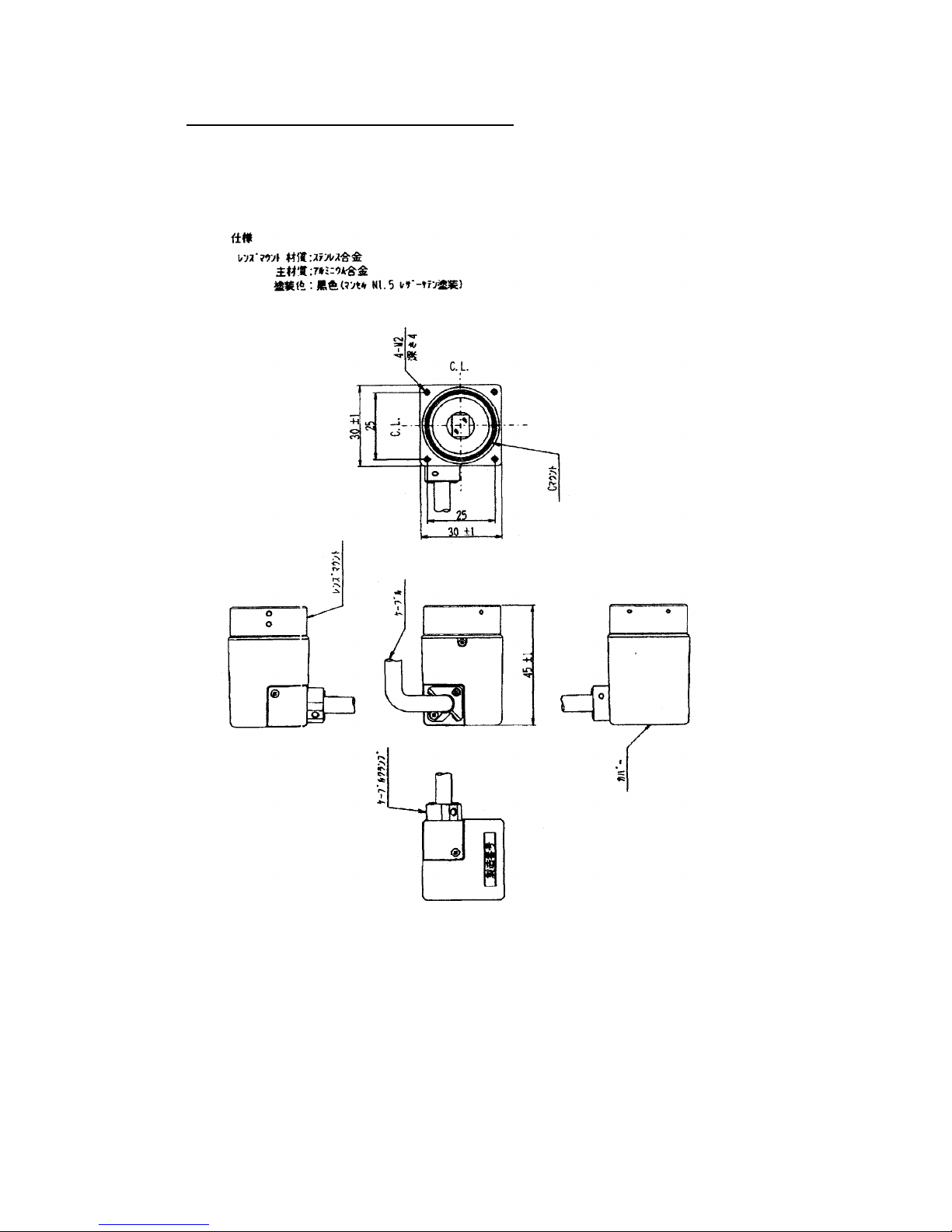
10. EXTERNAL-VIEW DRAWING
(1)Camera-head
28
Page 30
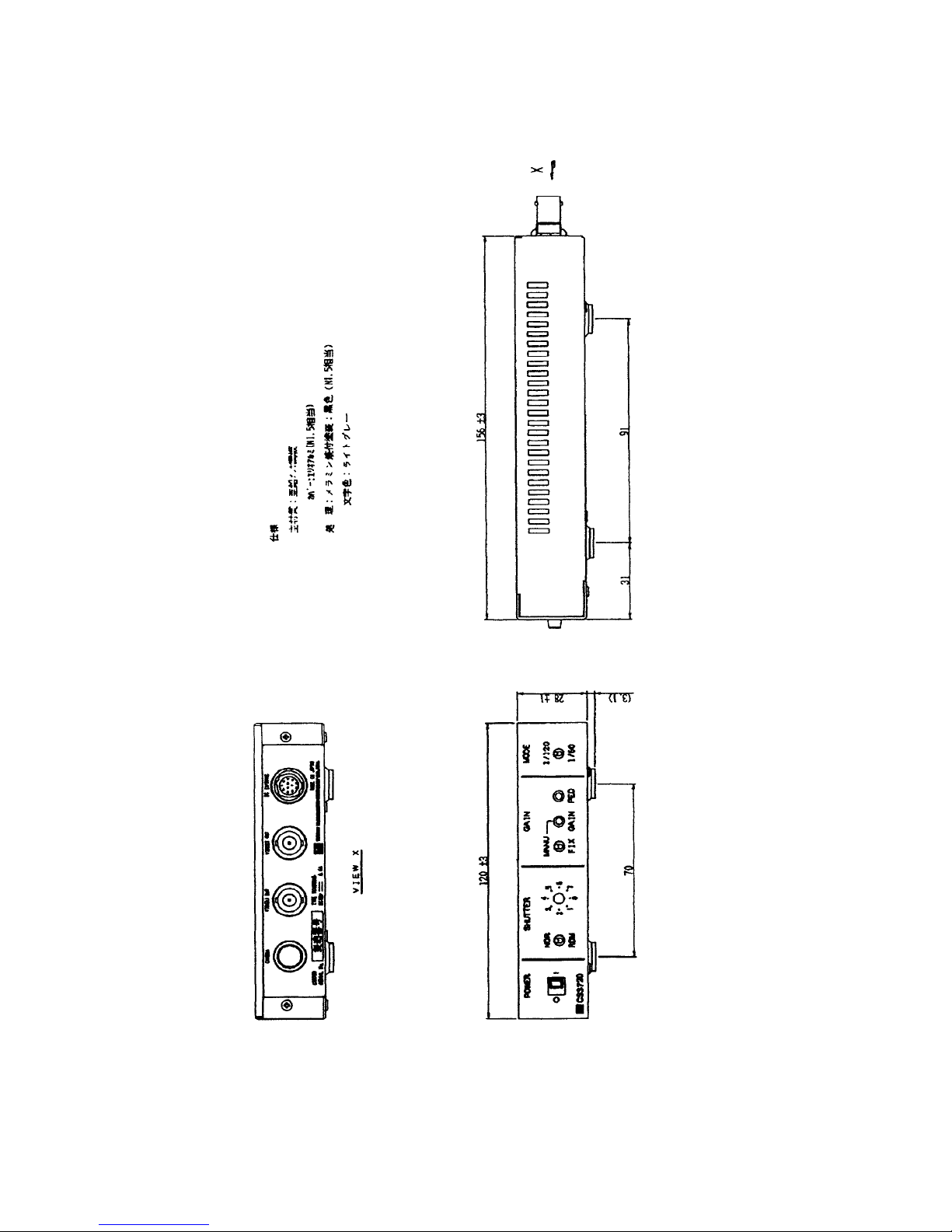
(2)
Camera control unit
29
Page 31

TOKYO ELECTRONIC INDUSTRY CO., LTD.
Head Office: 4-7-1, Asahigaoka, Hino-shi, Tokyo
191-0065, Japan
Phone: +81-(0)42-589-8771
FAX: +81-(0)42-589-8774
E-mail: [email protected]
Kansai Branch: Nitto Building, 2-1-2, Sakaemachi-dori,
Chuo-ku, Kobe, Hyogo 650-0023, Japan,
Phone : +81-(0)78-321-3461
FAX : +81-(0)78-321-3463
Fukuoka Office : Yen Building, 2-7-21, Hirao, Chuo-ku,
Fukuoka 810-0014, Japan
Phone : +81-(0)92-523-3395
FAX : +81-(0)92-523-3397
The design and specification is subject to change without notice.
30
 Loading...