

Telguard Digital TG-4 Quick Installation Manual
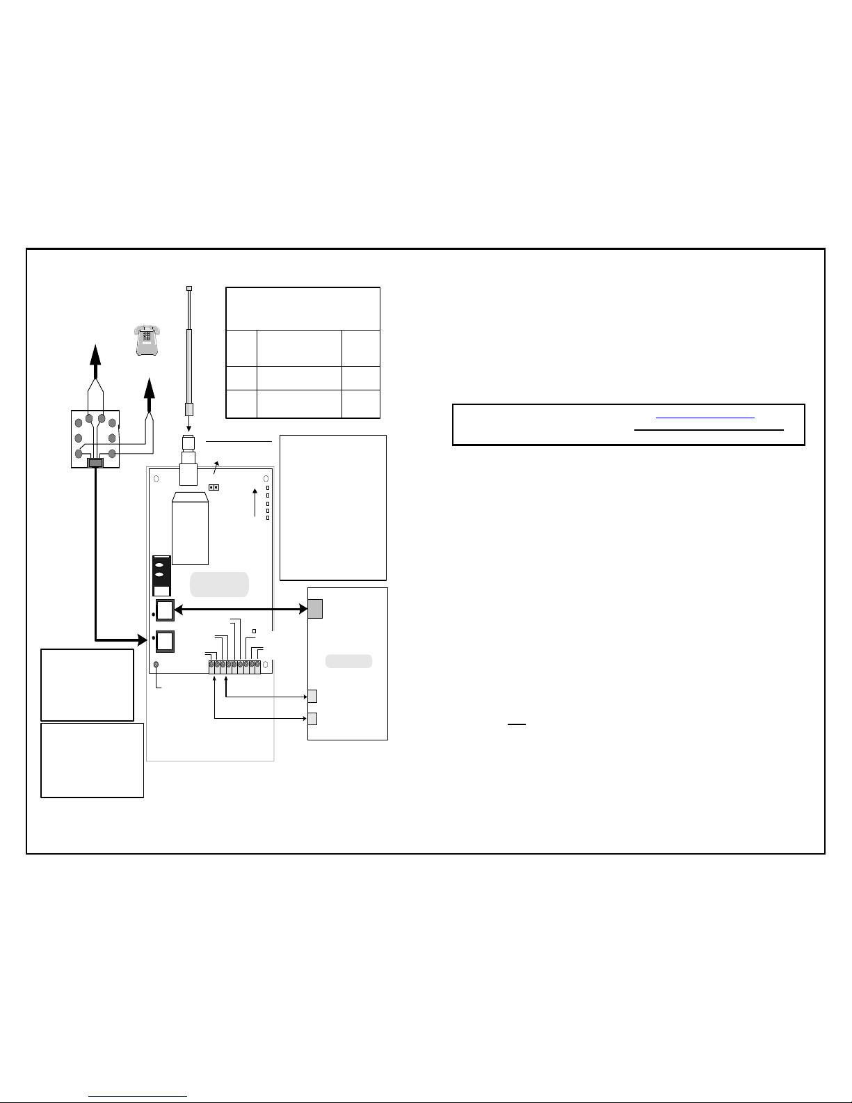
24 HOUR ZONE (N.C.)
24 HOUR ZONE (N.O.)
TELCO DIALER
ANTENNA
T
R
1234567
J6
TELGUARD
Digital TG-4
OPEN = NORMAL
SIGNAL
STRENGTH
LEDS
2
3
4 5
6
7
GREEN
R
8
1
T
RED
PREMISE
PHONE
INCOMING
TELCO
RJ31X
www.Telguard.com
REFER TO INSTALLATION AND OPERATING INSTRUCTIONS MANUAL.
THIS DEVICE COMPLIES WITH FCC RULES PART 68 AND 15.
TELULAR CORPORATION
420 Thornton Road, Suite 109
Lithia Springs, GA 30122
(800) 229-2326
Fax: 678-945-1651
8 9
+
_
J
P
4
J7
SIM
J10
SHORTED = RSSI
HOST C/C
1
2
3
4
5
SYSTEM STATUS LEDS
NORMAL MODE
LED #1 GREEN
REGISTRATION (See Table)
LED #2 RED
SYSTEM TROUBLE, STC (See Table)
LED #3 YELLOW
ON = MODE 1 (TELCO Primary)
OFF = MODE 2 (CELL Primary)
FLASH = C/C OFF HOOK CELL
LED #4 RED
ON = WAITING FOR RESPONSE
If flashing with LED #1 = DENIED(NACK)
LED #5 GREEN
ON = RADIO INITIALIZING
FLASH = COMMUNICATING
SYSTEM TROUBLE,
STC (LED #2)
1 FLASH = AC LOW/MISSING
2 FLASH = LBC LOW BATTERY
3 FLASH = LFC LINE FAULT
4 FLASH = NSC NO SERVICE
5 FLASH = RFC RADIO FAILU RE
6 FLASH = DTF DIAL TONE FAIL
REGISTRATION
(LED #1)
ON = UNIT REG ISTERED
OFF = UNIT N OT REGISTERED
If flashing with LED #4 = DENIED
(NACK)
,
Call Technical Support.
If all LED's flashing = NO RESPONSE,
Check Signal Strength.
SYSTEM STATUS LEDS
RSSI MODE
RSSI Value LED's Lig hted RF dBm
NO SVC LED 5*= flash, 4-2 = off n/a
1 LED 5 = on, 4-2 = off < -111 dBm
1 ½ LED 5 = on, 4 = flash, 3-2 = off > - 110 dBm
2 LED 5-4 = on, 3-2 = off > -100 dBm
2 ½
LED 5-4 = on, 3 = flash, 2 = off
> -90 dBm
(Minimum Signal Recommended)
3 LED 5-3 = on, 2 = off > -80 dBm
3 ½ LED 5-3 = on , 2 = flash > -70 dBm
4 LED 5-2 = on > -60 dBm
*Note: LED #1 ON INDICATES MORE THAN ONE TOWER
AC
LED 6
CAUTION:
INCORRECT CONNECTIONS
MAY RESULT IN DAMAGE TO UNIT.
WARNING:
HIGH VOLTAGE
PRESENT ON PHONE
LINES.
DISCONNECT PRIOR
TO SERVICING.
LED MODE SELECT
EARTH
GROUND
STC2
(N.C.)
STC1
(N.O.)
BATTERY
(12V)
BLANK PIN
AC
(12V 800MA)
Telguard Digital model TG-4
QUICK INSTALLATION GUIDE
Installation Summary
There are six steps in installing Telguard properly. IF YOU DO NOT
PROCEED IN THE ORDER AND MANNER PRESCRIBED, YOU MAY
NOT COMPLETE THE INSTALLATION IN THE TIME ALLOCATED.
STEP 1: REGISTER FOR CELLULAR SERVICE
Complete the Activation Form online at www.Telguard.com or fax
the form to Telular Cellular Service prior to leaving for the job site.
Telular requires this information to register and activate the unit.
STEP 2: LOCATE UNIT AND MEASURE SIGNAL STRENGTH (RSSI)
Second, you will be confirming that Telguard has adequate cellular signal
strength. Put J10 across both pins, LEDS will now indicate signal strength,
minimum recommended is 2 ½ (2 on solid and the third flashing).
STEP 3: TRANSMIT C/C ALARMS OVER THE TELCO CONNECTION
Connect C/C and telco line to the Telguard. Trip a simple alarm on the C/C
and transmit over the telco line. This step is important to verify that the C/C
is programmed with valid account code and central station information
before transmitting signals through the cellular network.
STEP 4: PROGRAM, ACTIVATE & TRANSMIT C/C ALARMS OVER
THE
CELLULAR RADIO NETWORK
Next, you will be programming the Telguard unless the default settings are
what you want. Then connect the C/C's digital dialer output to Telguard and
verify that alarm signals can be reliably sent over cellular to the central
station digital receiver. The incoming telco line is not connected to Telguard
during this step. A minimum of two alarm signals must be transmitted.
(NOTE:
THE FIRST ALARM WILL CONFIRM REGISTRATION AND
ACTIVATE THE UNIT WITH THE
TELULAR COMMUNICATION CENTER.
IT WILL NOT
BE TRANSMITTED TO THE CENTRAL STATION. ALL
SIGNALS AFTER THE FIRST ARE SENT TO THE
CENTRAL STATION.)
STEP 5: CONNECT SUPERVISORY TRIP OUTPUTS
Next, you will wire Telguard's supervisory trip outputs to the C/C and then test.
STEP 6: COMPLETE THE INSTALLATION
Your last step will be to check the jumper setting of J10 (LED mode, open =
normal), attach earth ground, and permanently mount the unit.
56033603
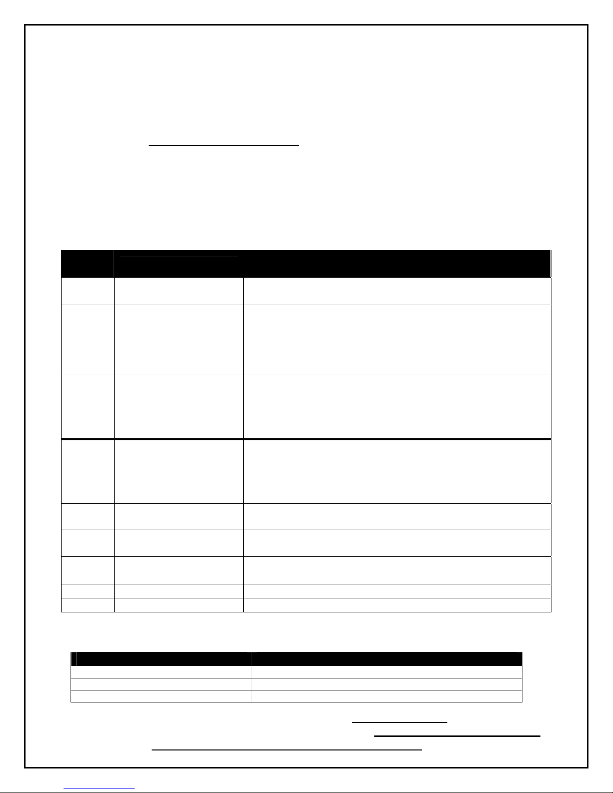
Setup & Programming the Operating Parameters in the Telguard
When the Telguard is received from the factory and is powered up for the first time, it is immediately ready to confirm
registration & activate, provided the default settings are what you want (Note: Activation Form must be sent to Telular
prior to activation). The STC LED #2 will flash to indicate any failure conditions. The yellow MODE LED #3 will be on
and the STC relay will be tripped. If changes are required to the default settings, the Telguard can be programmed
using a line-mans butt-set connected to T & R Test Points or a POTS phone connected to J7 (black connector where
the C/C is normally connected).
TO PROGRAM THE TELGUARD
A. Put the line-mans butt-set in talk mode or pick up the POTS phone.
B. Connect power to the Telguard, when ready for programming you will hear 2 beeps.
C. Press #, *, this will put the Telguard into a Master Access programming mode, 2 beeps.
D. Enter changes required. The syntax for programming a specific memory location is as follows:
MEMORY LOC. (3-digits), will respond with 2 beeps, then VALUE, will respond with 2 beeps.
E. Then press *, you will hear 2 beeps then hang up. This saves the change and exits the programming mode.
MEMORY
LOC.
831
833
FIELD
Mode of operation
C/C Reporting Format
DEFAULT
SETTINGS
VAULE
1 1 = Telco Primary/Cellular Backup
2 = Cellular Primary/Telco Backup
09
01= 4x2 pulse, 40pps 2300 hz 02= 4x2 pulse, 20pps 2300 hz
03= 4x2 pulse, 20pps 1400 hz 04= 3x1 pulse, 40pps, 2300 hz
05= 3x1 pulse, 20pps, 2300 hz 06= 3x1 pulse, 10pps, 1400 hz
07= Radionics IIe or IIIa
2
08 = Contact ID
09 = Auto Format Detect
11 = SIA2 (300 Baud) 12 = DMP
850 STC 1 Trip Output
Reporting
Normally
Open
851
STC 2 Trip Output
Reporting
Normally
Closed
852 STC Trip Delay for LFC
04
27
1
Enter the SUM TOTAL of the events that you wish to trip the
STC relay by ADDING the corresponding values:
00 = STC Trip Input Not Used
01 = AC Failure 04 = LFC 16 = RFC
02 = Low Battery 08 = NSC 31 = All
Enter the SUM TOTAL of the events that you wish to trip the
STC relay by ADDING the corresponding values:
00 = STC Trip Input Not Used
01 = AC Failure 04 = LFC 16 = RFC
02 = Low Battery 08 = NSC 31 = All
1=30 Seconds 2=60 Seconds
and NSC
861
CFC Number of Events
0
0 = disabled 2 = 4 attempts
1 = 2 attempts 3 = 8 attempts
862
CFC between Events
1
1 = 30 seconds 3 = 70 seconds 5 = 90 seconds
2 = 60 seconds 4 = 80 seconds 6 = 99 seconds
872
899
AC Failure Delay
Factory Default Unit
02
0-24 hours, default = 2 hours
NOTE: SPECIAL LED INDICATIONS DURING ACTIVATION
If the Telguard fails to confirm registration it will be displayed on the LEDS:
SYSTEM STATUS LEDS REGISTRATION INDICATIONS
ALL LEDS FLASHING FAILED REGISTRATION – SIGNAL TOO WEAK
LED #1 & LED #4 FLASHING REGISTRATION ERROR – CALL TECHNICAL SUPPORT
On either a FAILED or REGISTRATION ERROR, the unit MUST BE RESET by putting the J10
(RSSI jumper) in the “SHORTED” position. The registration MESSAGE MUST BE RESENT or
the TELGUARD will transmit all signals through the telco connection
LED #1 ON REGISTRATION SUCCESSFUL
.
 Loading...