

Telguard TG-4 Quick Installation Manual
24
HOUR ZONE
(N
.
C
.)
TELCO DIALER
T
R
1
2
3 5 6
1 2
SIM
1
2
3
4
5
6
7
8
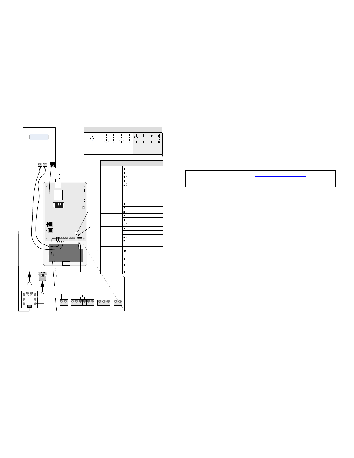
Power LED
EARTH
GROUND
LED Mode
Toggle Button
4
LEDs 2-5
Signal (dBm)
NO
SVC
< -110 > -110 > -100 > -90 > -80 > -70 > -60
RSSI (bars) NONE 1½1 2 2½ 3 3½
System Status LEDs (RSSI Mode)
OFF
BLINKING
ON
System Status
LEDs
Alarm Panel
Battery
Connector
Acceptable RSSI Range
BATTERY
Battery wire
should be at
least ¼ inch
apart from
AC wires
Not Used
Not Used
1 2 1 32
4
1 2 1 2 3 4 5 6
1 21 2 3
AC
+
-
OPTIONAL
BATTERY
STC2
(N.C)
STC1
(N.O.)
GND
IN
TRIP
2
3
4
5
6
6
7
GREEN
R
8
8
1
T
RED
INCOMING
TELCO
RJ31X
24
HOUR ZONE
(
N
.
O
.)
TELGUARD
Digital TG-4
GND DC
1 FLASH = ACFC LOW/MISSING AC
LPF LOW DC INPUT
2 FLASH = LBC LOW BATTERY
3 FLASH = LFC LINE FAULT
4 FLASH = NSC NO SERVICE
5 FLASH = RFC RADIO FAILURE
6 FLASH = DTF DIAL TONE FAIL
7 FLASH = PPF PNL PRES FAIL
LED 1
OFF NOT ACTIVATED
ACTIVATEDON
System Status LEDs (Normal Mode)
ACTIVATION DENIED (DISABLED)FLASHING
ACTIVATION
LED 2
OFF
FLASHING
SYSTEM
TROUBLE
NO TROUBLE
TROUBLE:
LED 3
OFF
ON
PANEL COMM
PANEL ON-HOOK (PRIMARY)
PANEL ON-HOOK (BACKUP)
LED 4
OFF IDLE
WAITING FOR RESPONSE FROM
TCC
ON
ACTIVATION DENIEDFLASHING
TMC COMM
LED 5
OFF IDLE
RADIO INITIALIZINGON
RADIO COMMUNICATINGFLASHING
RADIO STATUS
PANEL OFF-HOOKFLASHING
LED 6
LED 7LED 8
OFF
NOT USED
OFF
NOT USED
NOT USED
NOT USED
AC NOT CONNECTED
UNIT MAY BE RECEIVING
POWER FROM DC/BATTERY
OFF
POWER LED
FLASHING
STANDARD LINE SECURITY ENABLED
(2 FLASHES EVERY 5 SECONDS)
AC
(12V 800MA)
AC CONNECTED TO UNITON
Telguard Model TG-4
QUICK INSTALLATION GUIDE
Installation Summary
There are seven steps in installing Telguard properly. IF YOU DO NOT
PROCEED IN THE ORDER AND MANNER PRESCRIBED, YOU MAY
NOT COMPLETE THE INSTALLATION IN THE TIME ALLOCATED.
STEP 1: REGISTER FOR CELLULAR SERVICE
Register the unit online through www.telguardonline.com, by
completing the Online Registration Form at www.Telguard.com. Telular
requires this information to activate the unit.
STEP 2: LOCATE UNIT AND MEASURE SIGNAL STRENGTH (RSSI)
First, you will be confirming that Telguard has adequate cellular signal strength. Press the LED
Mode Toggle button, LEDs will now indicate signal strength. Minimum recommended is 2 ½
(2 on solid and the third flashing). ). The LED Mode will reset to normal automatically after 10
minutes or after pressing the LED Mode Toggle button again.
STEP 3: TRANSMIT PANEL ALARMS OVER THE TELCO CONNECTION
Next, you will verify that the alarm panel is programmed properly. This step is important to
verify that the alarm panel is programmed with valid account code and central station
information before transmitting signals through the cellular network.
STEP 4: PROGRAM, ACTIVATE & TRANSMIT PANEL ALARMS OVER
THE CELLULAR RADIO NETWORK
Next, you will be connecting the alarm panel's digital dialer output to Telguard and verifying that
alarm signals can be reliably sent through Telguard over cellular to the central station digital
receiver. The incoming Telco line is not connected to Telguard during this step. A minimum of
two alarm signals must be transmitted. Activation is confirmed when LED 1 is illuminated.
(NOTE: THE FIRST ALARM WILL ACTIVATE THE UNIT AT THE TELULAR COMMUNICATION
CENTER, IT WILL NOT GO TO THE CENTRAL STATION, ALL SIGNALS AFTER THE FIRST ARE
SENT TO THE CENTRAL STATION)
STEP 5: CONNECT SUPERVISORY TRIP OUTPUTS
Next, you will wire Telguard's supervisory trip outputs to the alarm panel and then test.
STEP 6: CONNECT TRIP INPUT (OPTIONAL)
Optionally, you can wire an external relay input to the trip input lead and ground, and test.
STEP 7: COMPLETE THE INSTALLATION
Your last step will be to attach earth ground, and permanently mount the unit.
56044002

Setup & Programming the Operating Parameters in the Telguard TG-4
Mem Loc.
Field
Default Value
Setting
831
Mode of operation
01
1 = Telco Primary/Cellular Backup
2 = Cellular Primary/Telco Backup
3 = Cell Only
833
C/C Reporting Format
09
01 = 4x2 pulse, 40pps 2300 hz 02 = 4x2 pulse, 20pps 2300 hz
03 = 4x2 pulse, 10pps 1400 hz 04 = 3x1 pulse, 40pps, 2300 hz
05 = 3x1 pulse, 20pps, 2300 hz 06 = 3x1 pulse, 10pps, 1400 hz
07 = Radionics IIe or IIIa2 08 = Contact ID
09 = Auto Format Detect 11 = SIA2 (300 Baud)
12 = DMP
850
STC1 Trip Output
Reporting
Normally Open
04
(LFC only)
Enter the SUM TOTAL of the events that you wish to trip the STC relay by
ADDING the corresponding values:
00 = Not Used 04 = LFC 32 = DTF
01 = AC Failure 08 = NSC 63 = ALL
02 = Low Battery 16 = RFC
851
STC2 Trip Output
Reporting
Normally Closed
59
(all except LFC)
Enter the SUM TOTAL of the events that you wish to trip the STC relay by
ADDING the corresponding values:
00 = Not Used 04 = LFC 32 = DTF
01 = AC Failure 08 = NSC 63 = ALL
02 = Low Battery 16 = RFC
852
STC Trip Delay for NSC
2 (60 sec)
1=30 seconds 4=10 minutes 7=45 minutes
2=60 seconds 5=20 minutes 8=60 minutes
3=3 minutes 6=30 minutes 9=24 hours
858
STC History
N/A
0 = terminate STC history display mode
1 = start STC history display mode
2 = clear STC history
861
CFC Number of Events
0 (disabled)
0 = disabled 2 = 4 attempts
1 = 2 attempts 3 = 8 attempts
862
CFC Between Events
1 (30 sec)
1 = 30 seconds 3 = 70 seconds 5 = 90 seconds
2 = 60 seconds 4 = 80 seconds 6 = 99 seconds
868
PPF Delay
0 (disabled)
0 = disabled, 1 = 10 sec onds, 2=20 seconds, … 15=15 0 seconds
872
AC Failure Delay
02 (2 hours)
0-24 hours
873
Trip Input Reporting
0 (no report)
0 = no report 1 = report trip
874
Trip Input Restoral Reporting
0 (no report)
0 = no report 1 = report restoral
875
Trip Input Swinger Function
0 (disabled)
0 = swinger function disabled
1 = swinger function enabled
899
Factory Default Unit
System Status LEDs
Activation Indications
ALL LEDS FLASHING
FAILED ACTIVATION – SIGNAL TOO WEAK
LED #1 & LED #4 FLASHING
ACTIVATION ERROR – CALL TECH SUPPORT
LED #1 ON
ACTIVATION SUCCESSFUL
LED #2 OFF
NOT ACTIVATED. NEED TO CONNECT PANEL AND TRIP ZONE
When the Telguard is received from the factory and is powered up for the first time, it is immediately ready for activation, provided the default settings
are what you want (note: registration form must be sent to Telular). The STC LED # 2 will flash to indicate any failure conditions. The Mode LED # 3
will be on and the STC 1 and STC 2 relays will be tripped. If changes are required to the default settings, the Telguard can be programmed using a
line-mans butt-set connected to T & R Test Points or a POTS phone connected to the panel RJ-45 jack (black connector where the alarm panel is
normally connected).
TO PROGRAM THE Telguard TG-4
A. Put the line-mans butt-set in talk mode or pick up the POTS phone.
B. Connect power to the Telguard, when ready for programming you will hear 2 beeps.
C. Press #, *, this will put the Telguard into a Master Access programming mode, 2 beeps.
D. Enter changes required. The syntax for programming a specific memory location is as follows:
MEMORY LOCATION (3-digits), will respond with 2 beeps, then VALUE, will respond with 2 beeps.
E. Then press *, you will hear 2 beeps then hang up. This saves the change and exits the programming mode.
NOTE: SPECIAL LED INDICATIONS DURING ACTIVATION
If the Telguard fails to confirm activation it will be displayed on the LEDS:
On either a FAILED ACTIVATION or ACTIVATION ERROR, the unit MUST BE RESET BY PRESSING THE RSSI
BUTTON TWICE. The activation message MUST BE RESENT or the TELGUARD will transmit all signals through
the telco connection.
 Loading...